US6320897B1 - Multicode spread spectrum communications system - Google Patents
Multicode spread spectrum communications system Download PDFInfo
- Publication number
- US6320897B1 US6320897B1 US09/389,394 US38939499A US6320897B1 US 6320897 B1 US6320897 B1 US 6320897B1 US 38939499 A US38939499 A US 38939499A US 6320897 B1 US6320897 B1 US 6320897B1
- Authority
- US
- United States
- Prior art keywords
- symbols
- stream
- multicoded
- plural sets
- modulated
- Prior art date
- Legal status (The legal status is an assumption and is not a legal conclusion. Google has not performed a legal analysis and makes no representation as to the accuracy of the status listed.)
- Expired - Lifetime
Links
Images


Classifications
-
- H—ELECTRICITY
- H04—ELECTRIC COMMUNICATION TECHNIQUE
- H04B—TRANSMISSION
- H04B1/00—Details of transmission systems, not covered by a single one of groups H04B3/00 - H04B13/00; Details of transmission systems not characterised by the medium used for transmission
- H04B1/69—Spread spectrum techniques
- H04B1/707—Spread spectrum techniques using direct sequence modulation
-
- H—ELECTRICITY
- H04—ELECTRIC COMMUNICATION TECHNIQUE
- H04J—MULTIPLEX COMMUNICATION
- H04J13/00—Code division multiplex systems
- H04J13/0077—Multicode, e.g. multiple codes assigned to one user
-
- H—ELECTRICITY
- H04—ELECTRIC COMMUNICATION TECHNIQUE
- H04J—MULTIPLEX COMMUNICATION
- H04J13/00—Code division multiplex systems
- H04J13/10—Code generation
-
- H—ELECTRICITY
- H04—ELECTRIC COMMUNICATION TECHNIQUE
- H04B—TRANSMISSION
- H04B1/00—Details of transmission systems, not covered by a single one of groups H04B3/00 - H04B13/00; Details of transmission systems not characterised by the medium used for transmission
- H04B1/69—Spread spectrum techniques
- H04B1/707—Spread spectrum techniques using direct sequence modulation
- H04B1/709—Correlator structure
Definitions
- the invention deals with the field of multiple access communications using Spread Spectrum modulation.
- Multiple access can be classified as either random access, polling, TDMA, FDMA, CDMA or any combination thereof.
- Spread Spectrum can be classified as Direct Sequence, Frequency-Hopping or a combination of the two.
- DSSS Direct Sequence Spread Spectrum
- CDMA Code Division Multiple Access
- DSSS See Simon M. K. et al., “Spread Spectrum Communications Handbook,” Revised Edition, McGraw-Hill, 1994 and see Dixon, R. C., “Spread Spectrum systems with commercial applications,” Wiley InterScience, 1994) is a communication scheme in which information symbols are spread over code bits (generally called chips). It is customary to use noise-like codes called pseudo-random noise (PN) sequences. These PN sequences have the property that their auto-correlation is almost a delta function. In other words, proper codes perform an invertible randomized spreading of the information sequence.
- PN pseudo-random noise
- the transmitted signal can be buried in noise and thus has a low probability of intercept.
- the receiver can recover the signal from interferers (such as other transmitted codes) with a jamming margin that is proportional to the spreading code length.
- DSSS codes of duration longer than the delay spread of the propagation channel can lead to multipath diversity implementable using a Rake receiver.
- the FCC and Industry Canada have allowed the use of unlicensed low power DSSS systems of code lengths greater than or equal to 10 (part 15 rules) in some frequency bands (the ISM bands).
- CDMA Code Division Multiple Access
- BS Base Station
- MS Mobile Stations
- the MSs share one carrier frequency during the mobile-to-base link (also known as the reverse link) which is 45 MHz away from the one used by the BS during the base-to-mobile link (also known as the forward link).
- the BS transceiver is assigned N codes where N is less than or equal to M and M is the number of chips per DSSS code.
- each MS is assigned a unique code.
- Synchronization on the reverse link synchronization is complex (especially) if the BS receiver does not know in advance either the identity of the code being transmitted, or its time of arrival.
- MCSS Type III both the near-far problem and the synchronization problem that exist on the reverse link of a CDMA system are reduced drastically by using MCSS Type III.
- each user is assigned one code and each code is assigned a guard time such that it starts to transmit only after a given amount of time relative to any adjacent codes.
- MCSS Type III forces the codes to be (quasi) orthogonal as long as the guard time between adjacent codes is long enough.
- a MCSS receiver When viewed as DSSS, a MCSS receiver requires up to N correlators (or equivalently up to N Matched Filters) (such as in QUALCOMM Inc,. “An overview of the application of Code Division Multiple Access (CDMA)” to digital cellular systems and personal cellular networks, May 21, 1994 and as in Viterbi, A. J., “CDMA, Principles of Spread Spectrum Communications,” Addison-Wesley, 1995) with a complexity of the order of NM operations. When both N and M are large, this complexity is prohibitive.
- a nonideal communication channel can cause InterCode Interference (ICI), i.e. interference between the N SS codes at the receiver.
- ICI InterCode Interference
- MCSS Type I allows the information in a MCSS signal to be detected using a sequence of partial correlations with a combined complexity of the order of M operations.
- MCSS Type II allows the information in a MCSS signal to be detected in a sequence of low complexity parallel operations while reducing the ICI.
- MCSS Type III allows the information in a MCSS signal to be detected in a sequence of low complexity Multiply and Accumulate (MAC) operations implementable as a filter, which reduce the effect of multipath.
- MAC Multiply and Accumulate
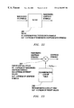
- FIG. 1 provides an illustration of a Transmitter for MCSS Type I, wherein VB data symbols in VBT seconds are input and PM multicoded SS symbols in PMT C seconds are output;
- FIG. 2 provides a schematic illustration of a Spreader Type I ( 104 ) from FIG. 1, in which P frames of J modulated symbols each are input and P frames of N spread spectrum symbols each, of length M chips per spread spectrum symbol are output;
- FIG. 3 provides a schematic of the ith computing means ( 202 ) from FIG. 2, in which an ith subset of modulated symbols is input and an ith spread spectrum symbol of length M chips is output;
- FIG. 4 provides a schematic of the ith source ( 302 ) from FIG. 3 of L i spread spectrum codes, in which L i preset sequences of length M chips each are input, and L i spread spectrum codes of length M chips each are output;
- FIG. 5 provides a schematic of the ith source ( 302 ) from FIG. 3 of L i spread spectrum codes, in which L i preset values of length M chips each are input, and L i spread spectrum codes of length M chips each are output;
- FIG. 6 provides a schematic of the Transmitter for MCSS Type II, in which VB data symbols in VBT seconds are input, and PM multicoded SS symbols in PMT C seconds are output;
- FIG. 7 provides a schematic of the Spreader Type II ( 604 ) from FIG. 6, in which P frames of J modulated symbols each are input and P frames of M multicoded SS symbols are output;
- FIG. 8 provides the ith M-point Transform ( 702 ) from FIG. 7, in which M subsets of modulated symbols are input and M multicoded SS symbols are output;
- FIG. 9 provides the ith M-point Transform ( 702 ) from FIG. 7, in which M subsets of modulated symbols are input and M multicoded SS symbols are output;
- FIG. 10 provides a schematic of the MCSS Transmitter Type III, in which a stream of data symbols is input and a stream of ramped multicoded SS symbols is output;
- FIG. 11 provides a schematic of the Spreader ( 1002 ) Type III in FIG. 10, in which a sequence of modulated symbols is input and a sequence of multicoded SS symbols is output;
- FIG. 12 provides a schematic of the Randomizer ( 1101 ) in FIG. 11, in which a sequence of modulated symbols is input and a sequence of randomized modulated symbols is output;
- FIG. 13 provides a schematic of the Computing Means ( 1102 ) in FIG. 11, in which a sequence of randomized modulated symbols is input and a sequence of multicoded SS symbols is output;
- FIG. 14 provides a schematic of the Ramper ( 1003 ) in FIG. 10 for ramping the multicoded SS symbols using a linearly ramping carrier frequency, in which a sequence of multicoded SS symbols is input and a sequence of ramped multicoded SS symbols is output;
- FIG. 15 provides a schematic of the Receiver for MCSS Type I & II, in which PM multicoded SS symbols in PMT C seconds is input and VB estimated data symbols in VBT seconds is output;
- FIG. 16 provides a schematic of the Despreader Type I ( 1503 ) from FIG. 15, in which P frames of M multicoded SS symbols each are input and P frames of J despread symbols each is output;
- FIG. 17 provides a schematic of the ith computing means ( 1602 ) from FIG. 16, in which M multicoded SS symbols are input and ith computed values are output;
- FIG. 18 provides a schematic of the Despreader Type II ( 1503 ) from FIG. 15, in which P frames of M multicoded SS symbols each are input and P frames of J despread symbols each are output;
- FIG. 19 provides a schematic of the Receiver for MCSS Type III, in which a stream of multicoded SS symbols are input and a stream of estimated data symbols are output;
- FIG. 20 provides the De-ramper ( 1901 ) in FIG. 19 for de-ramping the ramped milticoded SS symbols using a linearly de-ramping carrier frequency, in which a stream of ramped multicoded SS symbols are input and an estimated stream of multicoded SS symbols are output;
- FIG. 21 provides a schematic of the De-Spreader ( 1902 ) Type III in FIG. 19, in which a sequence of multicoded SS symbols is input and a sequence of detected symbols is output;
- FIG. 22 provides a schematic of the computing means ( 2101 ) in FIG. 21, in which a stream of multicoded SS symbols is input and a stream of randomized despread symbols is output;
- FIG. 23 provides a schematic of the De-Randomizer ( 2102 ) in FIG. 21, in which a sequence of randomized despread data symbols is input and a sequence of despread symbols is output;
- FIG. 24 provides a preferred diversity receiver for MCSS Type III with de-ramping, in which a stream of ramped multicoded SS symbols is input and a stream of estimated data symbols is output.
- the description of the invention consists of six parts. The first three parts correspond to the transmitter for each one of the three types of MCSS introduced in this patent, while the last three parts correspond to the receiver for each one of the three types of MCSS.
- FIG. 1 illustrates a block diagram of the transmitter for MCSS Type I with an input of V frames of B data symbols each, every VBT seconds and an output of P frames of M multicoded SS symbols each, every PMT C seconds where T is the duration of one data symbol and T C is the duration of one chip in a spread spectrum code.
- the data symbols can be either analog or digital. If digital, they belong to an alphabet of finite size. If analog, they correspond to the samples of an analog signal.
- FIG. 1 is described as follows:
- the first block in FIG. 1 is a serial-to-parallel converter ( 101 ) with an input of B data symbols and an output of one frame of B data symbols, every BT seconds.
- the second block is a 2 Dimensional (2D) shift register ( 102 ) with an input of V frames of B data symbols each (input by shifting the frames from left to right V times) and an output of Q frames of B data symbols each, every VBT seconds.
- 2D 2 Dimensional
- the third block ( 103 ) in FIG. 1 corresponds to an analog pulse modulator with several possible modulation schemes such as Pulse Amplitude Modulation (PAM), Pulse Position Modulation (PPM), Pulse Frequency Modulation (PFM), etc.
- PAM Pulse Amplitude Modulation
- PPM Pulse Position Modulation
- PFM Pulse Frequency Modulation
- the third block is a channel encoder/modulator ( 103 ) with an input of Q frames of B data symbols each and an output of P frames of J modulated symbols each, every QBT seconds.
- the channel encoder/modulator performs two functions: (1) to encode and (2) to modulate the data symbols.
- the first function offers protection to the symbols against a non ideal communication channel by adding redundancy to the input sequence of data symbols while the second function maps the protected symbols into constellation points that are appropriate to the communication channel.
- Sometimes it is possible to perform the two functions simultaneously such as in the case of Trellis Coded Modulation (TCM).
- TCM Trellis Coded Modulation
- the code rate is Q/P, i.e. the encoder takes Q data symbols in and generates P encoded data symbols out where P>Q. Furthermore, if V ⁇ Q then (V ⁇ 1) is the constraint length of the convolutional encoder.
- Another possible form of interleaving is to interleave the coded data symbols after the channel encoder (not shown in FIG. 1 ).
- BPSK Binary Phase Shift Keying
- QPSK Quadrature Phase Shift Keying
- MPSK Multilevel Phase Shift Keying
- QAM Quadrature Amplitude Modulation
- FSK Frequency Shift Keying
- CPM Continuous Phase Modulation
- ASK Amplitude Shift Keying
- All amplitude and frequency modulation schemes can be demodulated either coherently or noncoherently.
- All phase modulation schemes can demodulated either coherently or differentially.
- differential encoding is required in the modulator such as in Differential BPSK (DBPSK), Differential QPSK (DQPSK), Differential MPSK (DMPSK), etc.
- DBPSK Differential BPSK
- DQPSK Differential QPSK
- DMPSK Differential MPSK
- the fourth block is a spreader type I ( 104 ) with an input of P frames of J modulated symbols each and an output of P frames of N spread spectrum symbols each, of length M chips per spread spectrum symbol, every PMT C seconds.
- the spreader type I ( 104 ) is explained further below in FIGS. 2-5.
- the fifth block is a 3 Dimensional (3D) shift register ( 105 ) with an input of P frames of N spread spectrum symbols each (input by shifting the PN symbols from inside to outside M chip times), and an output of M frames of N chips each (output by shifting MN chips from left to right P times) every PMT C seconds.
- 3D 3 Dimensional
- the sixth block is a set of M adders ( 106 ). Each adder has an input of N chips and an output of one multicoded SS symbol, every MT C seconds.
- the seventh block is a parallel-to-serial converter ( 107 ) with an input of one frame of M multicoded SS symbol and an output of M multicoded SS symbol every MT C seconds.
- the spreader type I ( 104 ) in FIG. 1 is described further in FIG. 2 with an input of P frames of J modulated symbols each, generated by the channel encoder/modulator ( 103 ) in FIG. 1, and an output of P frames of N spread spectrum symbols each, of length M chips per spread spectrum symbol.
- FIG. 2 is described as follows:
- the first block in FIG. 2 is a set of P converters ( 201 ) with an input of one frame of J modulated symbols per converter, and an output of one frame of N subsets of modulated symbols per converter.
- the second block is a set of N computing means ( 202 ) with an input of one subset of modulated symbols per computing means, and an output of one spread spectrum symbol, of length M chips per computing means.
- the ith computing mean has as an input the ith subset of modulated symbols, and as an output the ith spread spectrum symbol of length M chips.
- FIG. 3 is described as follows.
- the first block in FIG. 3 is the ith mapper ( 301 ) with two inputs and one output.
- the two inputs are: (1) the ith subset of modulated symbols which contains a number J i of modulated symbols, and (2) L i spread spectrum codes of length M chips each.
- the output is the ith spread spectrum symbol.
- the ith mapper chooses from the set of L i spread spectrum codes the code corresponding to the ith subset of modulated symbols to become the ith spread spectrum code representing an invertible randomized spreading of the ith subset of modulated symbols.
- the second block in FIG. 3 is the ith source ( 302 ) of L i spread spectrum codes with an output of L i spread spectrum codes of length M chips each.
- the ith source ( 302 ) can be thought of as either a lookup table or a code generator. Two different implementations of the ith source are shown in FIGS. 4 and 5.
- the invertible randomized spreading of a signal using a spreader is only invertible to the extent of the available arithmetic precision of the machine used to implement the spreader. In other words, with finite precision arithmetic, the spreading is allowed to add a limited amount of quantization noise.
- the randomized spreading of a signal is not a perfect randomization of the signal (which is impossible) but only a pseudo-randomization. This is typical of spread spectrum techniques in general.
- the ith source ( 302 ) of FIG. 3 can also be generated as in FIG. 4 as a set of L i transforms with an input of one preset sequence of length M chips per transform and an output of one spread spectrum code of length M chips per transform.
- the ith source of spread spectrum codes could be either a look-up table containing the codes such as in FIG. 3 or a number of transforms generating the codes such as in FIG. 4 .
- the ith source ( 302 ) of FIG. 3 can also be generated as in FIG. 5 as two separate blocks.
- the first block ( 501 ) consists of a set of L i transforms with an input of one preset sequence of length M chips per transform and an output of one spread spectrum code of length M chips per transform.
- the second block is a randomizing transform ( 502 ) with an input of L i transformed codes of length M chips each generated by the first block ( 501 ) and an output of L i spread spectrum codes of length M chips each.
- the randomizing transform consists of two parts.
- the first part is a randomizing look-up table ( 503 ) which contains a set of M preset values: a 1,i , a 2,i , . . . ,a M,i .
- the second part multiplies each transformed symbol from the set of transformed symbols generated by the first transform ( 501 ) by the set of M preset values generated by the randomizing look-up table ( 503 ).
- FIG. 6 illustrates a block diagram of the transmitter for MCSS Type II with an input of VB data symbols every VBT seconds and an output of PM multicoded SS symbols every PMT C seconds.
- FIG. 6 is described as follows:
- the first block in FIG. 6 is a serial-to-parallel converter ( 601 ) with an input of B data symbols and an output of one frame of B data symbols, every BT seconds.
- the second block is a 2 Dimensional (2D) shift register ( 602 ) with an input of V frames of B data symbols each (input by shifting the frames from left to right V times) and an output of Q frames of B data symbols each, every VBT seconds.
- 2D 2 Dimensional
- the third block is a channel encoder/modulator ( 603 ) with an input of Q frames of B data symbols each and an output of P frames of J modulated symbols each, every QBT seconds.
- the function of the channel encoder/modulator is exactly the same as the channel encoder/modulator ( 103 ) described above for MCSS type I in FIG. 1 .
- the fourth block is a spreader type II ( 604 ) with an input of P frames of J modulated symbols each and an output of P frames of M multicoded SS symbols each, every PMT C seconds.
- the spreader type II is explained further below in FIGS. 7-9.
- the fifth block is a 2 Dimensional (2D) shift register ( 605 ) with an input of P frames of M multicoded SS symbols each, and an output of P frames of M multicoded SS symbols each (output by shifting the M frames from left to right P times) every PMT C seconds.
- 2D 2 Dimensional
- the sixth block is a parallel-to-serial converter ( 606 ) with an input of one frame of M multicoded SS symbols and an output of M multicoded SS symbols every MT C seconds.
- the spreader type II ( 604 ) in FIG. 6 is described further in FIG. 7 with an input of P frames of J modulated symbols each, generated by the channel encoder/modulator ( 603 ) in FIG. 6, and an output of P frames of M multicoded SS symbols each.
- FIG. 7 is described as follows:
- the first block in FIG. 7 is a set of P converters ( 701 ) with an input of one frame of J modulated symbols per converter, and an output of one frame of M subsets of modulated symbols per converter.
- the second block is a set of P M-point transforms ( 702 ) with an input of M subsets of modulated symbols per transform, and an output of a frame of M multicoded SS symbols per transform.
- the P M-point transforms perform the invertible randomized spreading of the M subsets of modulated symbols.
- the input of the ith transform is the ith subset of J i modulated symbols, and the output is the ith frame of M multicoded SS symbols.
- the ith M-point transform is the randomizing transform ( 801 ) similar to the randomizing transform ( 502 ) in FIG. 5 with the set of preset values given as: a 1,i , a 2,i , . . . , a M,i .
- the kth preset value a k,i multiplies the kth subset of J k modulated symbols to generate the kth multicoded SS symbol.
- the ith M-point transform ( 801 ) in FIG. 8 can further include a second M-point transform ( 902 ) as described in FIG. 9 .
- the first M-point transform ( 901 ) is the ith randomizing transform with an input of the ith subset of J i modulated symbols, and an output of the ith frame of M transformed symbols.
- the second M-point transform ( 902 ) is the ith second M-point transform with an input of the ith frame of transformed symbols, and an output of the ith frame of M multicoded SS symbols.
- FIG. 10 illustrates a block diagram of the transmitter for MCSS Type III with an input of a stream of data symbols and an output of a stream of multicoded SS symbols.
- FIG. 10 is described as follows:
- the first block is a channel encoder/modulator ( 1001 ) with an input of a stream of data symbols and an output of a stream of modulated symbols.
- the function of the channel encoder/modulator is similar to the channel encoder/modulator for MCSS types I and II ( 103 ) and ( 603 ) respectively except its operation is serial.
- Such a representation is commonly used in textbooks to implicitly imply that the data rate of the output stream of modulated symbols could be different from the input stream of data symbols.
- the channel encoder/modulator can add redundancy to the input stream of data symbols to protect it against channel distortion and noise.
- the type of redundancy varies depending on the type of encoding used. In block encoding, the redundancy depends only on the current block of data. In convolutional encoding, it depends on the current block and parts of the previous block of data. In both types of encoding trellis coding can be used which modulates the modulated symbols output from the encoder.
- FIG. 10 does not contain an interleaver, it is possible to include one either before the channel encoder/modulator or after.
- the second block is a spreader type III ( 1002 ) with an input of a stream of modulated symbols and an output of a stream of multicoded SS symbols.
- the spreader type III is further explained in FIGS. 11-13.
- the third block is a ramper ( 1003 ) with an input of multicoded SS symbols and an output of a ramped multicoded SS symbols.
- the ramper is further explained in FIG. 14 .
- the spreader type II ( 1002 ) in FIG. 10 is describe further in FIG. 11 as two blocks with an input of a stream of modulated symbols, generated by the channel encoder/modulator ( 1001 ) in FIG. 10, and an output of a stream of multicoded SS symbols.
- the first block is a randomizer ( 1101 ) with an input of a stream of modulated symbols and an output of a randomized modulated symbols.
- the randomizer is described further in FIG. 12 .
- the second block is a computing means ( 1102 ) with an input of the stream of randomized modulated symbols and an output of a stream of multicoded SS symbols.
- the computing means is described further in FIG. 13 .
- FIG. 12 the randomizer ( 1101 ) from FIG. 11 is described further as two parts.
- the first part is a chip-by-chip multiplier ( 1201 ) with two inputs and one output.
- the first input is the stream of modulated symbols and the second input is a stream of preset values output from a randomizing lookup table ( 1202 ).
- the output is the product between the two inputs obtained chip-by-chip, i.e. the kth randomized modulated symbols is obtained by multiplying the kth modulated symbol with the kth preset value a k .
- the second part is the randomizing lookup table ( 1202 ) which is the source of a stream of preset values: . . . ,a k ,a k+1 , . . .
- the randomizing sequence is only pseudo-randomizing the modulated symbols.
- the computing means ( 1102 ) from FIG. 11 is described further as a filter which performs the invertible randomized spreading of the stream of modulated symbols.
- FIG. 14 illustrates the ramper ( 1003 ) in FIG. 10 as a mixer with two inputs and one output.
- the first input is the stream of multicoded SS symbols
- FIG. 15 illustrates a block diagram of the receiver for MCSS type I & II with an input of PM multicoded SS symbols, every PMT C seconds and an output of VB estimated data symbols, every VBT seconds.
- FIG. 15 is described as follows:
- the first block in FIG. 15 is a serial-to-parallel converter ( 1501 ) with an input of M multicoded SS symbols and an output of one frame of M multicoded SS symbols every MT C seconds.
- the second block is a 2 Dimensional (2D) shift register ( 1502 ) with an input of one frame of M multicoded SS symbols each (input by shifting the frame from left to right P times) and an output of P frames of M multicoded SS symbols each, every PMT C seconds.
- 2D 2 Dimensional
- the third block is a despreader type I ( 1503 ) with an input of P frames of M multicoded SS symbols each and an output of P frames of J despread symbols each every PMT C seconds.
- the despreader type I is further explained below.
- the fourth block is a channel decoder/demodulator ( 1504 ) with an input of P frames of J despread symbols each and an output of V frames of B estimated data symbols each, every VBT seconds.
- the channel decoder/demodulator performs two functions: (1) to map the despread symbols into protected data symbols and (2) either to detect errors, or to correct errors, or both. Sometimes, the two functions can be performed simultaneously. In this case, the channel decoder/demodulator performs soft-decision decoding, otherwise, it performs hard-decision decoding. By performing the two function, the channel encoder/demodulator accepts the despread symbols and generates estimated data symbols
- the fifth block is a 2 Dimensional (2D) shift register ( 1505 ) with an input of V frames of B estimated data symbols each, and an output of V frames of B estimated data symbols (output by shifting the V frames from left to right) every VBT seconds. If the 2D shift register ( 102 ) is operated with B>1, then it might act as an interleaver. In this case, the receiver requires a de-interleaver which is accomplished using the 2D shift register ( 1505 ).
- the sixth block is a parallel-to-serial converter ( 1506 ) with an input of one frame of B estimated data symbols and an output of B estimated data symbols, every VBT seconds.
- the despreader type I ( 1504 ) in FIG. 15 is described further in FIG. 16 with an input of P frames of M multicoded SS symbols each from the received sequence of multicoded SS symbols, and an output of P frames of J despread symbols each.
- FIG. 16 is described as follows:
- the first block in FIG. 16 is a set of P parallel-to-serial converters ( 1601 ) with an input of one frame of M multicoded SS symbols per converter, and an output of M multicoded SS symbols per converter.
- the second block is a set of N computing means ( 1602 ) each having the same input of M multicoded SS symbols and an output of one computed value per computing means.
- the third block is a detector ( 1603 ) with an input of N computed values and an output of J despread symbols per detector.
- the detector can make either hard decisions or soft decisions.
- the ith computing mean has as an input the M multicoded SS symbols, and as an output the ith computed value.
- FIG. 17 is described as follows.
- the first block in FIG. 17 is a set of L i partial correlators ( 1701 ).
- the first input consists of the M multicoded SS symbols and the second input consists of the nth spread spectrum code of length M chips out of the ith source of L i spread spectrum codes.
- the output of the nth partial correlator is the nth partially correlated value obtained by correlating parts of the first input with the corresponding parts of the second input.
- the second block is the ith source ( 1702 ) of L i spread spectrum codes with an output of L i spread spectrum codes of length M chips each.
- the third block is the ith sub-detector ( 1703 ) with an input of L i partially correlated values and an output of the ith computed value.
- the ith sub-detector has two tasks. First using the L i partially correlated values it has to obtain the full correlation between the M multicoded SS symbols and each one of the L i spread spectrum codes of length M chips obtained from the ith source ( 1702 ). Then, it has to select the spread spectrum code corresponding to the largest correlation. Such a detected spread spectrum code together with the corresponding full correlation value form the ith computed value.
- the detector ( 1703 ) in FIG. 16 takes all the computed values from each one of the N computing means and outputs J despread symbols. Based on the function of each sub-detector, one can say that the detector ( 1603 ) has two tasks at hand. First, it has to map each detected spread spectrum code into a first set of despread symbols, then it has to map each full correlation value into a second set of despread symbols. In other words, the first set of despread symbols correspond to spread spectrum codes that form a subset of the spread spectrum codes corresponding to the second set of despread symbols.
- the tasks of the detector are first to map each detected spread spectrum code (obtained through the several layers of sub-detection) into sets of despread symbols, then to map each full correlation value into a final set of despread symbols.
- FIG. 15 illustrates a block diagram of the receiver for MCSS Type II with an input of PM multicoded SS symbols every PMT C seconds and an output of VB estimated data symbols every VBT seconds.
- FIG. 15 illustrates also the block diagram of the receiver for MCSS Type I and has been described above.
- the despreader type II ( 1504 ) in FIG. 15 is described further in FIG. 18 with an input of P frames of M multicoded SS symbols each, and an output of P frames of J despread symbols each.
- FIG. 18 is described as follows:
- the first block in FIG. 18 is a set of P M-point transforms ( 1801 ) with an input of one frame of M multicoded SS symbols per transformer, and an output of M transformed symbols per transformer.
- the second block is a set of P detectors ( 1802 ) with an input of M transformed symbols per detector, and an output of J despread symbols per detector. Once again the detector can either make soft decisions or hard decisions.
- FIG. 19 illustrates a block diagram of the receiver for MCSS Type III with an input of a stream of ramped multicoded SS symbols and an output of a stream of estimated data symbols.
- FIG. 19 is described as follows:
- the first block in FIG. 19 is a de-ramper ( 1901 ) with an input of the stream of ramped multicoded SS symbols and an output of an estimated stream of multicoded SS symbols.
- the de-ramper is further described in FIG. 20 .
- the second block is a de-spreader Type III ( 1902 ) with an input of the estimated stream of multicoded SS symbols and an output of a stream of detected symbols.
- the de-spreader type II is further explained in FIG. 21-23.
- the third block is a channel decoder/demodulator ( 1903 ) with the input consisting of the stream of detected symbols, and an output of a stream of estimated data symbols. It is clear from FIG. 19 that no de-interleaver is included in the receiver. As mentioned above, if an interleaver is added to the transmitter in FIG. 10, then FIG. 19 requires a de-interleaver.
- FIG. 20 illustrates the deramper ( 1901 ) in FIG. 19 as a mixer with two inputs and one output.
- the first input is the ramped multicoded SS symbols and the second input is a linearly ramping carrier frequency which deramps the ramped multicoded SS stream thereby generating an estimated stream of multicoded SS symbols.
- the despreader type III ( 1902 ) in FIG. 19 is described further in FIG. 21 as three blocks.
- the first block is a computing means ( 2101 ) with an input of an estimated stream of multicoded SS symbols and an output of a stream of randomized despread symbols.
- FIG. 22 describes the computing means ( 2101 ) in FIG. 21 as a filter ( 2201 ) which performs the despreading process.
- the second block is a de-randomizer ( 2102 ) with an input of a stream of randomized despread symbols and an output of a stream of despread symbols.
- the de-randomizer ( 2102 ) is described further in FIG. 23 .
- the third block is a detector ( 2103 ) with an input of a stream of despread symbols and an output of a stream of detected symbols.
- the detector is a hard-decision detector it makes a decision on the despread symbols such that the detected values takes a finite number of values out of a predetermined alphabet of finite size.
- the detector is a soft-decision detector the detected symbols are the same as the despread symbols.
- the de-randomizer ( 2102 ) is described further in FIG. 23 as two parts.
- the first part is a chip-by-chip multiplier ( 2301 ) with two inputs and an output.
- the first input is a stream of randomized despread data symbols and the second input is a stream of preset values output from a de-randomizing lookup table ( 2302 ).
- the output is the chip-by-chip product between the two inputs, i.e. the kth despread symbol is obtained as the product between the kth randomized despread symbol and the kth preset value b k .
- the second part is a de-randomizing lookup table ( 2302 ) which outputs a stream of preset values: . . . ,b k ,b k+1 , . . .
- the contribution of the invention is primarily in the spreader in the transmitter and in the despreader in the receiver for each one of the three type of MCSS introduced in the patent.
- the secondary contribution of the patent resides in the channel encoder/modulator and in the extra components that can be used in both the transmitter and in the receiver for each three types such as: the ramping and de-ramping of the signal and diversity techniques.
- the spreader Type I ( 104 ) performs an invertible randomized spreading of the modulated symbols which carry either digital information or analog information, and in FIG. 15 the despreader Type I ( 1503 ) performs a reverse operation to the spreader Type I ( 104 ) within the limits of available precision (i.e. with some level of quantization noise).
- the spreader Type I ( 104 ) performs an invertible randomized spreading of the modulated
- the despreader Type I ( 1503 ) performs a reverse operation to the spreader Type I ( 104 ) while taking into account the effects of the communications channel such as noise, distortion and interference.
- the effects of the channel are sometimes unknown to the receiver (e.g. over selective fading channels which cause intersymbol interference).
- the channel has to be estimated using for example a pilot signal known to the receiver as in “MultiCode Direct Sequence Spread Spectrum,” by M. Fattouche and H. Zaghloul, U.S. Pat. No. 5,555,268, September 1996.
- a preferred function for the ith mapper is to choose one spread spectrum code (out of the L i available codes) based on one part of the ith subset of J i modulated symbols while the second part of the subset is used to choose the symbol that multiplies the chosen spread spectrum code.
- the kth spread spectrum code S k is chosen by the ith mapper ( 301 ) (out of the L i available codes) based on the first part of the ith subset of J i modulated symbols and that the symbol ⁇ is chosen to multiply S k based on the second part of the ith subset of J i modulated symbols
- the ith spread spectrum symbol out of the ith mapper ( 301 ) is S k ⁇ . This is equivalent to spreading ⁇ over S k .
- ⁇ can be chosen as a DBPSK symbol, a DQPSK symbol, a DMPSK symbol, a QAM symbol, a FSK symbol, a CPM symbol, an ASK symbol, etc.
- the L i spread spectrum codes, out of the ith source ( 302 ) of L i available spread spectrum codes, correspond to Walsh codes.
- Each Walsh code in FIG. 3 is generated in FIG. 4 as the output of an M-point Walsh transform where the input is a preset sequence of length M chips with (M ⁇ 1) chips taking a zero value while one chip taking a unity value.
- the L i spread spectrum codes, out of the ith source ( 302 ) of L i available spread spectrum codes, correspond to randomized Walsh codes.
- Each Walsh code generated in FIG. 4 as the output of an M-point Walsh transform is randomized in FIG. 5 using a chip-by-chip multiplier where the kth chip of each Walsh code is multiplied by the preset value a k,i output from the ith randomizing lookup table.
- preset values ⁇ a 1,i ,a 2,i , . . . ,a M,i ⁇ are chosen such that their amplitudes:
- a preferred value for L i is 2 and a preferred value for M is 10 with the two preferred spread spectrum codes out of the ith source ( 302 ) taking the values:
- the spreader Type II ( 604 ) performs an invertible randomized spreading of the modulated symbols which carry either digital information or analog information
- the despreader Type II ( 1503 ) performs a reverse operation to the spreader Type II ( 604 ) within the limits of available precision (i.e. with some level of quantization noise).
- the spreader Type II ( 604 ) performs an invertible randomized spreading of the modulated
- the despreader Type II ( 1503 ) performs a reverse operation to the spreader Type II ( 604 ) while taking into account the effects of the communications channel such as noise, distortion and interference.
- the effects of the channel are sometimes unknown to the receiver (e.g. over selective fading channels which cause intersymbol interference).
- the channel has to be estimated using for example a pilot signal known to the receiver as in “MultiCode Direct Sequence Spread Spectrum,” by M. Fattouche and H. Zaghloul, U.S. Pat. No. 5,555,268, September 1996.
- Pilot Frames inserted either before, during or after the Data frames of M multicoded SS symbols.
- Pilot frames estimate the long term effects of the channel, while pilot symbols estimate the short term effects of the channel.
- phase modulation such as BPSK, QPSK and MPSK
- differential detection is selected instead with differentially-encoded phase modulation such as DPSK, DQPSK and DMPSK.
- phase modulation such as ASK and QAM
- differential detection is selected instead with differentially-encoded phase and amplitude modulation such as Differential QAM using the star constellation.
- a preferred modulation technique is QAM when the channel is estimated and its effects removed.
- DMPSK DMPSK when the effects of the channel are not removed.
- a reference symbol is chosen at the beginning of each frame output from the channel modulator/modulator ( 603 ).
- a preferred value for B is unity when using a Reed-Solomon encoder, i.e. no interleaver is required in this case.
- preferred values for ⁇ a 1,i ,a 2,i , . . . ,a M,i ⁇ are such that their amplitudes:
- preferred ith second M-point transform is a Discrete Fourier Transform (DFT).
- DFT Discrete Fourier Transform
- the MCSS transmitter is similar to the one in the issued patent: “Method and Apparatus for Multiple Access between Transceivers in Wireless Communications using OFDM Spread Spectrum,” by M. Fattouche and H. Zaghloul, U.S. Pat. No. 5,282,222, Jan. 25, 1994.
- the channel encoder as a Reed-Solomon encoder without an interleaver are referred to as the ‘Wi-LAN codes Type II’.
- Another preferred embodiment of the ith second M-point transform ( 902 ) is a Circular FIR (CFIR) filter of length M coefficients which performs an M-point circular convolution between each block of M modulated symbols and its own coefficients.
- CFIR Circular FIR
- a preferred embodiment of the M-point transform ( 1801 ) is also a CFIR filter of length M coefficients which performs the inverse operation of the spreading CFIR filter by performing an M-point circular convolution between each block of M multicoded SS symbols and its own coefficients.
- the despreading CFIR filter can also invert the effects of the channel using either
- a linear algorithm such as Zero Forcing Equalization (ZFE) and Minimum Mean Square Equalization (MMSE); or
- DFE Decision Feedback Equalization
- ML Maximum Likelihood
- the effect of a nonideal frequency-selective communication channel is to cause the multicodes to loose their orthogonality at the receiver.
- the CFIR filter acts as a decorrelating filter which decorrelates the M multicoded symbols from one another at the receiver thereby forcing the symbols to be orthogonal.
- An advantage of using CFIR filter for spreading and despreading the data symbols is that IF-sampling can be inherently employed in the MCSS receiver without increasing the complexity of the digital portion of the receiver since interpolation and decimation filters can be included in the CFIR filters.
- the spreader Type III ( 1002 ) performs an invertible randomized spreading of the stream of modulated symbols which carry either digital information or analog information
- the despreader Type I ( 1902 ) performs a reverse operation to the spreader Type III ( 1002 ) within the limits of available precision (i.e. with some level of quantization noise).
- the spreader Type III ( 1002 ) performs an invertible randomized spreading of the stream of modulated symbols
- the despreader Type III ( 1902 ) performs a reverse operation to the spreader Type III ( 1002 ) while taking into account the effects of the communications channel such as noise, distortion and interference.
- the effects of the channel are sometimes unknown to the receiver (e.g. over selective fading channels which cause intersymbol interference).
- the channel has to be estimated using for example a pilot signal known to the receiver as in “MultiCode Direct Sequence Spread Spectrum,” by M. Fattouche and H. Zaghloul, U.S. Pat. No. 5,555,268 September 1996.
- a preferred randomizer ( 1101 ) in FIG. 11 is a trivial one with no effect on the modulated symbols.
- Another preferred randomizer ( 1101 ) is one where the preset values out of the randomizing lookup table ( 1202 ): ⁇ . . . ,a k ⁇ 1 ,a k ,a k+1 , . . . ⁇ have amplitudes which are equal to unity.
- a preferred filter is a Finite Impulse Response (FIR) filter with the coefficients obtained as the values of a polyphase code.
- FIR Finite Impulse Response
- a preferred filter is an FIR filter with the coefficients obtained as approximations to the values of a polyphase code.
- a preferred filter is an FIR filter with the following 16 coefficients:
- another preferred filter is an FIR filter with 64 coefficients corresponding to the following polyphase code:
- Another preferred filter in FIG. 13 with M coefficients corresponding to a binary approximation of a polyphase code can be obtained as the concatenation of the rows of an ⁇ square root over (M) ⁇ square root over (M) ⁇ matrix with the coefficient in the ith row and kth column determined as follows:
- Wi-LAN code Type III We refer to the spread spectrum code corresponding to the coefficients of a filter representing a binary approximation of a polyphase code as discussed above as the ‘Wi-LAN code Type III’.
- a preferred filter in FIG. 21 performs a reverse operation to the filter ( 1301 ) in FIG. 13 .
- FIG. 21 Another preferred filter in FIG. 21 performs a matching filtering operation to the filter ( 1301 ) in FIG. 13 .
- a preferred de-randomizer ( 2102 ) in FIG. 21 is one where the preset values out of the de-randomizing lookup table ( 2302 ): ⁇ . . . ,b k ⁇ 1 ,b k ,b k+1 , . . . ⁇ performs a reverse operation to the randomizer ( 1101 ) in FIG. 11 .
- FIG. 24 A preferred diversity technique for MCSS Type III is shown in FIG. 24 where we have L branches with one de-ramper ( 2401 ) per branch. Each de-ramper linearly de-ramps the received signal using a linearly deramping carrier frequency of fixed slope and unique intercept. Each intercept corresponds to a unique time of arrival of the different multipath components.
- the outputs of the L de-rampers are then combined in the combiner ( 2402 ) using any appropriate combining technique such as: co-phasing combining, maximum ratio combining, selection combining, equal gain combining, etc.
- the output of the combiner is then despread using the de-spreader ( 2403 ) and input into the channel decoder/demodulator ( 2404 ) to generate the estimated data symbols.
- a preferred value for f o in FIG. 14 is 1/(2 ⁇ MT C ) where ⁇ is the relative delay between the first arriving radio signal and the second arriving radio signal at the receiver, M is the number of coefficients in the spreading filter ( 1301 ) in FIG. 13 and T C is the duration of one chip (or equivalently it is the unit delay in the spreading filter ( 1301 )).
- the symbol rate at both the input and the output of the spreading filter ( 1301 ) is 1/T C .
Abstract
Description
Claims (46)
Priority Applications (1)
| Application Number | Priority Date | Filing Date | Title |
|---|---|---|---|
| US09/389,394 US6320897B1 (en) | 1996-10-03 | 1999-09-03 | Multicode spread spectrum communications system |
Applications Claiming Priority (2)
| Application Number | Priority Date | Filing Date | Title |
|---|---|---|---|
| US08/725,556 US6192068B1 (en) | 1996-10-03 | 1996-10-03 | Multicode spread spectrum communications system |
| US09/389,394 US6320897B1 (en) | 1996-10-03 | 1999-09-03 | Multicode spread spectrum communications system |
Related Parent Applications (1)
| Application Number | Title | Priority Date | Filing Date |
|---|---|---|---|
| US08/725,556 Continuation US6192068B1 (en) | 1996-10-03 | 1996-10-03 | Multicode spread spectrum communications system |
Publications (1)
| Publication Number | Publication Date |
|---|---|
| US6320897B1 true US6320897B1 (en) | 2001-11-20 |
Family
ID=24915024
Family Applications (2)
| Application Number | Title | Priority Date | Filing Date |
|---|---|---|---|
| US08/725,556 Expired - Lifetime US6192068B1 (en) | 1996-10-03 | 1996-10-03 | Multicode spread spectrum communications system |
| US09/389,394 Expired - Lifetime US6320897B1 (en) | 1996-10-03 | 1999-09-03 | Multicode spread spectrum communications system |
Family Applications Before (1)
| Application Number | Title | Priority Date | Filing Date |
|---|---|---|---|
| US08/725,556 Expired - Lifetime US6192068B1 (en) | 1996-10-03 | 1996-10-03 | Multicode spread spectrum communications system |
Country Status (1)
| Country | Link |
|---|---|
| US (2) | US6192068B1 (en) |
Cited By (73)
| Publication number | Priority date | Publication date | Assignee | Title |
|---|---|---|---|---|
| US20020009125A1 (en) * | 2000-06-12 | 2002-01-24 | Shi Zhen Liang | High bandwidth efficient spread spectrum modulation using chirp waveform |
| US20020136322A1 (en) * | 2001-03-23 | 2002-09-26 | Foma Feng | Method for asynchronously transmitting a serial data |
| US20020159422A1 (en) * | 2001-03-09 | 2002-10-31 | Xiaodong Li | Communication system using OFDM for one direction and DSSS for another direction |
| US6553019B1 (en) * | 1999-12-23 | 2003-04-22 | Flarion Technologies, Inc. | Communications system employing orthogonal frequency division multiplexing based spread sprectrum multiple access |
| US20030099280A1 (en) * | 2001-11-26 | 2003-05-29 | Kumar P. Vijay | Method and apparatus for generating a large number of codes having desirable correlation properties |
| US6690715B2 (en) * | 1999-06-29 | 2004-02-10 | Intersil Americas Inc. | Rake receiver with embedded decision feedback equalizer |
| US20040196782A1 (en) * | 2003-04-04 | 2004-10-07 | Interdigital Technology Corporation | Channel estimation method and system using fast fourier transforms |
| EP1480364A1 (en) * | 2002-02-28 | 2004-11-24 | Fujitsu Limited | Communication device used in cdma |
| US20050025079A1 (en) * | 2003-07-18 | 2005-02-03 | Shigeo Terabe | Mobile communication system, radio control station, base station and mobile station for the system, and parameter determination method employing parallel combinatory spread-spectrum scheme |
| US20050047367A1 (en) * | 2001-12-06 | 2005-03-03 | Ismail Lakkis | Ultra-wideband communication systems and methods |
| US20050053240A1 (en) * | 2003-09-09 | 2005-03-10 | Peter Lablans | Ternary and higher multi-value digital scramblers/descramblers |
| US20050069021A1 (en) * | 2001-12-06 | 2005-03-31 | Ismail Lakkis | Ultra-wideband communication apparatus and methods |
| US20050078736A1 (en) * | 2001-12-06 | 2005-04-14 | Ismail Lakkis | Ultra-wideband communication systems and methods |
| US20050094709A1 (en) * | 2001-12-06 | 2005-05-05 | Ismail Lakkis | Ultra-wideband communication apparatus and methods |
| US20050105595A1 (en) * | 2003-11-17 | 2005-05-19 | Martin Frederick L. | Communication device |
| US20050117557A1 (en) * | 2001-12-06 | 2005-06-02 | Ismail Lakkis | Ultra-wideband communication apparatus and methods |
| US20050135324A1 (en) * | 2003-12-17 | 2005-06-23 | Yun-Hee Kim | Apparatus for OFDMA transmission and reception for coherent detection in uplink of wireless communication system and method thereof |
| US20050152475A1 (en) * | 2001-12-06 | 2005-07-14 | Ismail Lakkis | Systems and methods for receiving data in a wireless communication network |
| US20050157782A1 (en) * | 2001-12-06 | 2005-07-21 | Ismail Lakkis | Systems and methods for transmitting data in a wireless communication network |
| US20050184888A1 (en) * | 2004-02-25 | 2005-08-25 | Peter Lablans | Generation and detection of non-binary digital sequences |
| US20050185796A1 (en) * | 2004-02-25 | 2005-08-25 | Peter Lablans | Ternary and multi-value digital signal scramblers, descramblers and sequence generators |
| US20050194993A1 (en) * | 2004-02-25 | 2005-09-08 | Peter Lablans | Single and composite binary and multi-valued logic functions from gates and inverters |
| US20050201473A1 (en) * | 2001-12-06 | 2005-09-15 | Ismail Lakkis | Systems and methods for receiving data in a wireless communication network |
| US20050201326A1 (en) * | 2001-12-06 | 2005-09-15 | Lakkis Ismail A. | Systems and methods for wireless communication over a wide bandwidth channel using a plurality of sub-channels |
| US20060021003A1 (en) * | 2004-06-23 | 2006-01-26 | Janus Software, Inc | Biometric authentication system |
| US20060031278A1 (en) * | 2004-08-07 | 2006-02-09 | Peter Lablans | Multi-value digital calculating circuits, including multipliers |
| US20060041818A1 (en) * | 2004-08-23 | 2006-02-23 | Texas Instruments Inc | Method and apparatus for mitigating fading in a communication system |
| US7031371B1 (en) | 2000-09-25 | 2006-04-18 | Lakkis Ismail A | CDMA/TDMA communication method and apparatus for wireless communication using cyclic spreading codes |
| WO2006049373A1 (en) * | 2004-11-02 | 2006-05-11 | Electronics And Telecommunications Research Institute | Apparatus and method for ultra wide band communication based on multi-coded bi-orthogonal pulse position modulation |
| US20070076820A1 (en) * | 2005-10-03 | 2007-04-05 | Chih-Yang Kao | Communication system with demodulation of two-level differential amplitude-shift-keying signals |
| US20070110229A1 (en) * | 2004-02-25 | 2007-05-17 | Ternarylogic, Llc | Ternary and Multi-Value Digital Signal Scramblers, Descramblers and Sequence of Generators |
| US7339955B2 (en) | 2000-09-25 | 2008-03-04 | Pulse-Link, Inc. | TDMA communication method and apparatus using cyclic spreading codes |
| US20080075033A1 (en) * | 2000-11-22 | 2008-03-27 | Shattil Steve J | Cooperative beam-forming in wireless networks |
| US20080095121A1 (en) * | 2002-05-14 | 2008-04-24 | Shattil Steve J | Carrier interferometry networks |
| US7406647B2 (en) | 2001-12-06 | 2008-07-29 | Pulse-Link, Inc. | Systems and methods for forward error correction in a wireless communication network |
| US20080267261A1 (en) * | 2007-04-25 | 2008-10-30 | Telefonaktiebolaget Lm Ericsson (Publ) | Efficient Computation of a Waveform Correlation Matrix |
| US7450637B2 (en) | 2001-12-06 | 2008-11-11 | Pulse-Link, Inc. | Ultra-wideband communication apparatus and methods |
| US7483483B2 (en) | 2001-12-06 | 2009-01-27 | Pulse-Link, Inc. | Ultra-wideband communication apparatus and methods |
| US20090069022A1 (en) * | 2007-09-12 | 2009-03-12 | Beceem Communications, Inc. | Method and system for estimating channel of a mobile station in a communication system |
| US20090128190A1 (en) * | 2004-02-25 | 2009-05-21 | Peter Lablans | Implementing Logic Functions with Non-Magnitude Based Physical Phenomena |
| US7548092B2 (en) | 2004-02-25 | 2009-06-16 | Ternarylogic Llc | Implementing logic functions with non-magnitude based physical phenomena |
| US7636382B1 (en) * | 2002-12-20 | 2009-12-22 | Cypress Semiconductor Corporation | Encoding Viterbi error states into single chip sequences |
| US20100067365A1 (en) * | 2006-06-14 | 2010-03-18 | Kyushu University, National University Corporation | Transmission system, transmission method, transmitter, receiver, decoding method, and decoder |
| US20100164548A1 (en) * | 2004-09-08 | 2010-07-01 | Ternarylogic Llc | Implementing Logic Functions With Non-Magnitude Based Physical Phenomena |
| US8045935B2 (en) | 2001-12-06 | 2011-10-25 | Pulse-Link, Inc. | High data rate transmitter and receiver |
| US20120294334A1 (en) * | 2010-01-11 | 2012-11-22 | Kiran Bynam | Ultra-wide band communication apparatus and method |
| US8374289B2 (en) | 2004-02-25 | 2013-02-12 | Ternarylogic Llc | Generation and detection of non-binary digital sequences |
| US8577026B2 (en) | 2010-12-29 | 2013-11-05 | Ternarylogic Llc | Methods and apparatus in alternate finite field based coders and decoders |
| US8731124B2 (en) * | 2012-03-28 | 2014-05-20 | Telefonaktiebolaget Lm Ericsson (Publ) | Signaling of sequence generator initialization parameters for uplink reference signal generation |
| US8942082B2 (en) | 2002-05-14 | 2015-01-27 | Genghiscomm Holdings, LLC | Cooperative subspace multiplexing in content delivery networks |
| US8971459B1 (en) * | 2001-01-12 | 2015-03-03 | Marvell International Ltd. | Receiver and method for incorporating channel state information into maximum ratio combining of a plurality of received signals |
| US9136931B2 (en) | 2002-05-14 | 2015-09-15 | Genghiscomm Holdings, LLC | Cooperative wireless networks |
| US9225471B2 (en) | 2002-05-14 | 2015-12-29 | Genghiscomm Holdings, LLC | Cooperative subspace multiplexing in communication networks |
| US9270421B2 (en) | 2002-05-14 | 2016-02-23 | Genghiscomm Holdings, LLC | Cooperative subspace demultiplexing in communication networks |
| US9628231B2 (en) | 2002-05-14 | 2017-04-18 | Genghiscomm Holdings, LLC | Spreading and precoding in OFDM |
| US9819449B2 (en) | 2002-05-14 | 2017-11-14 | Genghiscomm Holdings, LLC | Cooperative subspace demultiplexing in content delivery networks |
| US9893774B2 (en) | 2001-04-26 | 2018-02-13 | Genghiscomm Holdings, LLC | Cloud radio access network |
| US10142082B1 (en) | 2002-05-14 | 2018-11-27 | Genghiscomm Holdings, LLC | Pre-coding in OFDM |
| US10200227B2 (en) | 2002-05-14 | 2019-02-05 | Genghiscomm Holdings, LLC | Pre-coding in multi-user MIMO |
| US10355720B2 (en) | 2001-04-26 | 2019-07-16 | Genghiscomm Holdings, LLC | Distributed software-defined radio |
| US10425135B2 (en) | 2001-04-26 | 2019-09-24 | Genghiscomm Holdings, LLC | Coordinated multipoint systems |
| US10644916B1 (en) | 2002-05-14 | 2020-05-05 | Genghiscomm Holdings, LLC | Spreading and precoding in OFDM |
| US10880145B2 (en) | 2019-01-25 | 2020-12-29 | Genghiscomm Holdings, LLC | Orthogonal multiple access and non-orthogonal multiple access |
| US10931338B2 (en) | 2001-04-26 | 2021-02-23 | Genghiscomm Holdings, LLC | Coordinated multipoint systems |
| US11018918B1 (en) | 2017-05-25 | 2021-05-25 | Genghiscomm Holdings, LLC | Peak-to-average-power reduction for OFDM multiple access |
| US11115160B2 (en) | 2019-05-26 | 2021-09-07 | Genghiscomm Holdings, LLC | Non-orthogonal multiple access |
| US11184037B1 (en) | 2004-08-02 | 2021-11-23 | Genghiscomm Holdings, LLC | Demodulating and decoding carrier interferometry signals |
| US11196603B2 (en) | 2017-06-30 | 2021-12-07 | Genghiscomm Holdings, LLC | Efficient synthesis and analysis of OFDM and MIMO-OFDM signals |
| US11343823B2 (en) | 2020-08-16 | 2022-05-24 | Tybalt, Llc | Orthogonal multiple access and non-orthogonal multiple access |
| US11381285B1 (en) | 2004-08-02 | 2022-07-05 | Genghiscomm Holdings, LLC | Transmit pre-coding |
| US11552737B1 (en) | 2004-08-02 | 2023-01-10 | Genghiscomm Holdings, LLC | Cooperative MIMO |
| US11804870B2 (en) | 2004-01-29 | 2023-10-31 | Neo Wireless Llc | Channel probing signal for a broadband communication system |
| US11917604B2 (en) | 2019-01-25 | 2024-02-27 | Tybalt, Llc | Orthogonal multiple access and non-orthogonal multiple access |
Families Citing this family (35)
| Publication number | Priority date | Publication date | Assignee | Title |
|---|---|---|---|---|
| US6678311B2 (en) | 1996-05-28 | 2004-01-13 | Qualcomm Incorporated | High data CDMA wireless communication system using variable sized channel codes |
| FI102340B (en) * | 1997-01-16 | 1998-11-13 | Nokia Telecommunications Oy | Procedure for data communication and radio systems |
| US5955992A (en) | 1998-02-12 | 1999-09-21 | Shattil; Steve J. | Frequency-shifted feedback cavity used as a phased array antenna controller and carrier interference multiple access spread-spectrum transmitter |
| US7430257B1 (en) * | 1998-02-12 | 2008-09-30 | Lot 41 Acquisition Foundation, Llc | Multicarrier sub-layer for direct sequence channel and multiple-access coding |
| US7076168B1 (en) | 1998-02-12 | 2006-07-11 | Aquity, Llc | Method and apparatus for using multicarrier interferometry to enhance optical fiber communications |
| DK1072138T3 (en) * | 1998-04-14 | 2002-12-16 | Fraunhofer Ges Forschung | Method and apparatus for fine frequency synchronization in multi-carrier demodulation systems |
| US6366607B1 (en) * | 1998-05-14 | 2002-04-02 | Interdigital Technology Corporation | Processing for improved performance and reduced pilot |
| US6128330A (en) | 1998-11-24 | 2000-10-03 | Linex Technology, Inc. | Efficient shadow reduction antenna system for spread spectrum |
| US6449262B1 (en) * | 1999-04-07 | 2002-09-10 | Legerity | Method and apparatus for frequency shifting with a clock signal |
| DE69900409T2 (en) * | 1999-04-21 | 2002-06-27 | Alcatel Sa | CDMA multiple access method with improved capacity |
| US6278685B1 (en) * | 1999-08-19 | 2001-08-21 | Intellon Corporation | Robust transmission mode |
| US7986729B2 (en) * | 1999-10-28 | 2011-07-26 | Lightwaves Systems, Inc. | High bandwidth data transport system |
| JP2001285927A (en) * | 2000-03-29 | 2001-10-12 | Matsushita Electric Ind Co Ltd | Communication terminal and wireless communication method |
| US6430214B1 (en) * | 2000-05-22 | 2002-08-06 | Motorola, Inc. | Fading resistant multi-level QAM receiver |
| JP2001358692A (en) | 2000-06-14 | 2001-12-26 | Nec Corp | Orthogonal frequency-division multiplex modulating and demodulating circuit |
| NZ506558A (en) * | 2000-08-25 | 2003-04-29 | Ind Res Ltd | A broadband indoor communication system using ofdm |
| US6754283B1 (en) * | 2000-10-13 | 2004-06-22 | Mindspeed Technologies, Inc. | High speed trellis encoding for discrete multitone transceivers |
| NZ509688A (en) * | 2001-02-01 | 2003-06-30 | Ind Res Ltd | Maximum likelihood sychronisation (estimating time delay) for wireless digital communications system using a pilot symbol |
| US7349691B2 (en) * | 2001-07-03 | 2008-03-25 | Microsoft Corporation | System and apparatus for performing broadcast and localcast communications |
| US20050053121A1 (en) * | 2001-12-06 | 2005-03-10 | Ismail Lakkis | Ultra-wideband communication apparatus and methods |
| US7257156B2 (en) * | 2001-12-06 | 2007-08-14 | Pulse˜Link, Inc. | Systems and methods for equalization of received signals in a wireless communication network |
| US20050152483A1 (en) * | 2001-12-06 | 2005-07-14 | Ismail Lakkis | Systems and methods for implementing path diversity in a wireless communication network |
| US7327800B2 (en) * | 2002-05-24 | 2008-02-05 | Vecima Networks Inc. | System and method for data detection in wireless communication systems |
| US20040125125A1 (en) * | 2002-06-29 | 2004-07-01 | Levy Kenneth L. | Embedded data windows in audio sequences and video frames |
| US6925128B2 (en) | 2002-10-31 | 2005-08-02 | Motorola, Inc. | Method and apparatus for reducing a peak-to-average power ratio in an orthogonal frequency division multiplex signal |
| US20040092228A1 (en) * | 2002-11-07 | 2004-05-13 | Force Charles T. | Apparatus and method for enabling use of low power satellites, such as C-band, to broadcast to mobile and non-directional receivers, and signal design therefor |
| US7327795B2 (en) * | 2003-03-31 | 2008-02-05 | Vecima Networks Inc. | System and method for wireless communication systems |
| US20040192218A1 (en) * | 2003-03-31 | 2004-09-30 | Oprea Alexandru M. | System and method for channel data transmission in wireless communication systems |
| KR20060044126A (en) * | 2004-11-11 | 2006-05-16 | 삼성전자주식회사 | Apparatus and method for cell searching and synchronization in ofdma system |
| US7866259B2 (en) * | 2006-01-18 | 2011-01-11 | Innovative Products For Life Inc. | Centrifugal food degreaser |
| US8031670B2 (en) * | 2008-11-13 | 2011-10-04 | Telefonaktiebolaget L M Ericsson (Publ) | Systems and methods for selecting the size of a control region of a downlink subframe |
| US8850071B2 (en) * | 2010-05-10 | 2014-09-30 | Liaison Technologies, Inc. | Map intuition system and method |
| KR102341966B1 (en) * | 2015-11-05 | 2021-12-22 | 삼성전자주식회사 | Method and apparatus of transmitting/receiving for reducing peak to average power ratio in an orthogonal frequency division multiplexing system |
| CN115276892A (en) * | 2021-04-30 | 2022-11-01 | 上海华为技术有限公司 | Signal generation method, signal processing method and related equipment |
| CN117375662A (en) * | 2022-06-29 | 2024-01-09 | 维沃移动通信有限公司 | Signal processing method and communication device |
Citations (73)
| Publication number | Priority date | Publication date | Assignee | Title |
|---|---|---|---|---|
| US3485949A (en) | 1966-05-02 | 1969-12-23 | Gen Dynamics Corp | Differential phase shift keying receiver with information modulated on a plurality of tones |
| US3789149A (en) | 1969-07-30 | 1974-01-29 | Plessey Telecommunications Res | Code division multiplex system |
| US3956619A (en) | 1975-03-31 | 1976-05-11 | General Electric Company | Pipeline walsh-hadamard transformations |
| US3987374A (en) | 1974-11-21 | 1976-10-19 | International Business Machines Corporation | Multi-line, multi-mode modulator using bandwidth reduction for digital FSK and DPSK modulation |
| US4092491A (en) | 1977-04-04 | 1978-05-30 | Bell Telephone Laboratories, Incorporated | Differential encoding and decoding scheme for digital transmission systems |
| US4164628A (en) | 1977-06-06 | 1979-08-14 | International Telephone And Telegraph Corporation | Processor for multiple, continuous, spread spectrum signals |
| US4306308A (en) | 1979-09-14 | 1981-12-15 | Rca Corporation | Symbols communication system |
| US4457004A (en) | 1982-02-08 | 1984-06-26 | Bell Telephone Laboratories, Incorporated | Multidimensional channel coding |
| GB2146875A (en) | 1983-09-09 | 1985-04-24 | Racal Res Ltd | Communications systems |
| US4520490A (en) | 1983-08-05 | 1985-05-28 | At&T Information Systems Inc. | Differentially nonlinear convolutional channel coding with expanded set of signalling alphabets |
| CA1203576A (en) | 1977-08-22 | 1986-04-22 | Josef Gammel | Military radar - or radio communications transmission system |
| US4601005A (en) | 1981-12-31 | 1986-07-15 | The Secretary Of State For Defence In Her Britannic Majesty's Government Of The United Kingdom Of Great Britain And Northern Ireland | Receivers for navigation satellite systems |
| US4601045A (en) | 1984-08-03 | 1986-07-15 | Larse Corporation | Modulator-demodulator method and apparatus with efficient bandwidth utilization |
| US4615040A (en) | 1984-06-14 | 1986-09-30 | Coenco Ltd. | High speed data communications system |
| US4623980A (en) | 1981-05-09 | 1986-11-18 | Te Ka De Felten & Guilleaume Fernmeldeanlagen Gmbh | Method of processing electrical signals by means of Fourier transformations |
| US4641318A (en) | 1985-04-25 | 1987-02-03 | Bell Communications Research, Inc. | Method for improving the reliability of data transmission over Rayleigh fading channels |
| US4660215A (en) | 1983-12-07 | 1987-04-21 | Matsushita Electric Industrial Co., Ltd. | Transmitter/receiver system |
| US4694466A (en) | 1985-06-03 | 1987-09-15 | Itt Defense Communications, A Division Of Itt Corporation | Time sharing frequency synthesizer |
| US4713817A (en) | 1985-04-25 | 1987-12-15 | Codex Corporation | Multidimensional, convolutionally coded communication systems |
| US4731816A (en) | 1985-05-20 | 1988-03-15 | Telebit Corporation | Ensemble modem structure for imperfect transmission media |
| US4799214A (en) | 1985-12-23 | 1989-01-17 | Fujitsu Limited | Two-wire full duplex frequency division multiplex modem system having echo cancellation means |
| US4809299A (en) | 1987-05-05 | 1989-02-28 | Ho Kit Fun | Frequency independent information transmission system |
| US4829540A (en) | 1986-05-27 | 1989-05-09 | Fairchild Weston Systems, Inc. | Secure communication system for multiple remote units |
| US4868874A (en) | 1986-04-18 | 1989-09-19 | Hitachi, Ltd. | Echo canceller |
| US4881241A (en) | 1988-02-24 | 1989-11-14 | Centre National D'etudes Des Telecommunications | Method and installation for digital communication, particularly between and toward moving vehicles |
| US4893266A (en) | 1987-06-01 | 1990-01-09 | Motorola, Inc. | Alias tagging time domain to frequency domain signal converter |
| US4901307A (en) | 1986-10-17 | 1990-02-13 | Qualcomm, Inc. | Spread spectrum multiple access communication system using satellite or terrestrial repeaters |
| US4914699A (en) | 1988-10-11 | 1990-04-03 | Itt Corporation | High frequency anti-jam communication system terminal |
| US4928310A (en) | 1989-07-17 | 1990-05-22 | Westinghouse Electric Corp. | Pseudorandom pulse code generators using electro-optical XOR gates |
| US4933952A (en) | 1988-04-08 | 1990-06-12 | Lmt Radioprofessionnelle | Asynchronous digital correlator and demodulators including a correlator of this type |
| US4944009A (en) | 1988-02-25 | 1990-07-24 | Massachusetts Institute Of Technology | Pseudo-random sequence generator |
| US4979183A (en) | 1989-03-23 | 1990-12-18 | Echelon Systems Corporation | Transceiver employing direct sequence spread spectrum techniques |
| US5029180A (en) | 1989-03-23 | 1991-07-02 | Echelon Systems Corporation | Transceiver providing selectable frequencies and spreading sequences |
| US5034911A (en) | 1988-04-11 | 1991-07-23 | E-Systems, Inc. | Signal parameterizer |
| US5063560A (en) | 1986-02-04 | 1991-11-05 | Advanced Systems Research Pty. Limited | Spread-spectrum multiplexed transmission system |
| US5063574A (en) | 1990-03-06 | 1991-11-05 | Moose Paul H | Multi-frequency differentially encoded digital communication for high data rate transmission through unequalized channels |
| US5073899A (en) | 1988-07-13 | 1991-12-17 | U.S. Philips Corporation | Transmission system for sending two signals simultaneously on the same communications channel |
| US5089982A (en) | 1990-05-24 | 1992-02-18 | Grumman Aerospace Corporation | Two dimensional fast Fourier transform converter |
| US5103459A (en) | 1990-06-25 | 1992-04-07 | Qualcomm Incorporated | System and method for generating signal waveforms in a cdma cellular telephone system |
| US5128964A (en) | 1990-10-10 | 1992-07-07 | Intelligent Modem Corporation | Modulation method and apparatus for multicarrier data transmission |
| US5134464A (en) | 1990-11-16 | 1992-07-28 | North American Philips Corporation | Method and apparatus for the transmission and reception of a multicarrier digital television signal |
| US5151919A (en) | 1990-12-17 | 1992-09-29 | Ericsson-Ge Mobile Communications Holding Inc. | Cdma subtractive demodulation |
| US5157686A (en) | 1990-05-24 | 1992-10-20 | Cylink Corporation | Method and apparatus for the modulation of spread spectrum radio signals |
| US5166951A (en) | 1991-05-15 | 1992-11-24 | Scs Mobilecom, Inc. | High capacity spread spectrum channel |
| US5193094A (en) | 1990-03-07 | 1993-03-09 | Qualcomm Incorporated | Method and apparatus for generating super-orthogonal convolutional codes and the decoding thereof |
| US5210770A (en) | 1991-09-27 | 1993-05-11 | Lockheed Missiles & Space Company, Inc. | Multiple-signal spread-spectrum transceiver |
| US5228025A (en) | 1990-02-06 | 1993-07-13 | Centre National D'etudes Des Telecommunications | Method for the broadcasting of digital data, notably for radio broadcasting at a high bit-rate towards mobile receivers, with time-frequency interlacing and assistance in the acquisition of automatic frequency control, and corresponding receiver |
| US5235614A (en) | 1991-03-13 | 1993-08-10 | Motorola, Inc. | Method and apparatus for accommodating a variable number of communication channels in a spread spectrum communication system |
| EP0562868A2 (en) | 1992-03-27 | 1993-09-29 | WI-LAN Inc | Method and apparatus for multiple access between transceivers in wireless communication using OFDM spread spectrum |
| EP0567771A2 (en) | 1992-03-30 | 1993-11-03 | Alcatel SEL Aktiengesellschaft | Method, transmitter and receiver for the transmission of information with a variable traffic flow and a central station for the coordination of the different senders and receivers |
| US5268926A (en) | 1991-09-11 | 1993-12-07 | Societe Nationale D'etude Et De Construction De Moteurs D'aviation "S.N.E.C.M.A." | Method and apparatus for the simultaneous transmission of separate data signals |
| US5274629A (en) | 1990-02-06 | 1993-12-28 | Etat Francais and Telediffusion de France SA | Method for the broadcasting of digital data, notably for radio broadcasting at high bit rate towards mobile receivers, with time-frequency interlacing and coherent demodulation |
| US5278844A (en) | 1991-04-11 | 1994-01-11 | Usa Digital Radio | Method and apparatus for digital audio broadcasting and reception |
| US5282222A (en) | 1992-03-31 | 1994-01-25 | Michel Fattouche | Method and apparatus for multiple access between transceivers in wireless communications using OFDM spread spectrum |
| US5285474A (en) | 1992-06-12 | 1994-02-08 | The Board Of Trustees Of The Leland Stanford, Junior University | Method for equalizing a multicarrier signal in a multicarrier communication system |
| US5291515A (en) | 1990-06-14 | 1994-03-01 | Clarion Co., Ltd. | Spread spectrum communication device |
| US5307376A (en) | 1991-01-17 | 1994-04-26 | France Telecom | Device for the coherent demodulation of time-frequency interlaced digital data, with estimation of the frequency response of the transmission channel and threshold, and corresponsing transmitter |
| EP0605955A2 (en) | 1993-01-06 | 1994-07-13 | Glenayre Electronics, Inc. | Method and apparatus for compensating multipath fading and simulcast interference in a radio signal |
| US5345440A (en) | 1990-09-14 | 1994-09-06 | National Transcommunications Limited | Reception of orthogonal frequency division multiplexed signals |
| US5357541A (en) | 1989-03-23 | 1994-10-18 | Echelon Corporation | Transceiver providing selectable frequencies and spreading sequences |
| US5375140A (en) | 1992-11-24 | 1994-12-20 | Stanford Telecommunications, Inc. | Wireless direct sequence spread spectrum digital cellular telephone system |
| US5442625A (en) | 1994-05-13 | 1995-08-15 | At&T Ipm Corp | Code division multiple access system providing variable data rate access to a user |
| US5467367A (en) | 1991-06-07 | 1995-11-14 | Canon Kabushiki Kaisha | Spread spectrum communication apparatus and telephone exchange system |
| US5469469A (en) | 1993-12-07 | 1995-11-21 | University Of Massachusetts Lowell Research Foundation | Composite spread spectrum signal including modulator demodulator |
| US5479447A (en) | 1993-05-03 | 1995-12-26 | The Board Of Trustees Of The Leland Stanford, Junior University | Method and apparatus for adaptive, variable bandwidth, high-speed data transmission of a multicarrier signal over digital subscriber lines |
| US5487069A (en) | 1992-11-27 | 1996-01-23 | Commonwealth Scientific And Industrial Research Organization | Wireless LAN |
| US5550812A (en) | 1991-02-28 | 1996-08-27 | U.S. Philips Corporation | System for broadcasting and receiving digital data, receiver and transmitter for use in such system |
| US5555268A (en) * | 1994-01-24 | 1996-09-10 | Fattouche; Michel | Multicode direct sequence spread spectrum |
| US5596601A (en) | 1994-08-30 | 1997-01-21 | Lucent Technologies Inc. | Method and apparatus for spread spectrum code pulse position modulation |
| US5615209A (en) | 1995-07-26 | 1997-03-25 | Ericsson Inc. | Method and apparatus for CDMA signal orthogonalization |
| US5623511A (en) | 1994-08-30 | 1997-04-22 | Lucent Technologies Inc. | Spread spectrum code pulse position modulated receiver having delay spread compensation |
| US5761429A (en) | 1995-06-02 | 1998-06-02 | Dsc Communications Corporation | Network controller for monitoring the status of a network |
| US5960032A (en) * | 1995-09-20 | 1999-09-28 | The Hong Kong University Of Science & Technology | High speed data transmission using expanded bit durations in multiple parallel coded data streams |
-
1996
- 1996-10-03 US US08/725,556 patent/US6192068B1/en not_active Expired - Lifetime
-
1999
- 1999-09-03 US US09/389,394 patent/US6320897B1/en not_active Expired - Lifetime
Patent Citations (80)
| Publication number | Priority date | Publication date | Assignee | Title |
|---|---|---|---|---|
| US3485949A (en) | 1966-05-02 | 1969-12-23 | Gen Dynamics Corp | Differential phase shift keying receiver with information modulated on a plurality of tones |
| US3789149A (en) | 1969-07-30 | 1974-01-29 | Plessey Telecommunications Res | Code division multiplex system |
| US3987374A (en) | 1974-11-21 | 1976-10-19 | International Business Machines Corporation | Multi-line, multi-mode modulator using bandwidth reduction for digital FSK and DPSK modulation |
| US3956619A (en) | 1975-03-31 | 1976-05-11 | General Electric Company | Pipeline walsh-hadamard transformations |
| US4092491A (en) | 1977-04-04 | 1978-05-30 | Bell Telephone Laboratories, Incorporated | Differential encoding and decoding scheme for digital transmission systems |
| US4164628A (en) | 1977-06-06 | 1979-08-14 | International Telephone And Telegraph Corporation | Processor for multiple, continuous, spread spectrum signals |
| CA1203576A (en) | 1977-08-22 | 1986-04-22 | Josef Gammel | Military radar - or radio communications transmission system |
| US4306308A (en) | 1979-09-14 | 1981-12-15 | Rca Corporation | Symbols communication system |
| US4623980A (en) | 1981-05-09 | 1986-11-18 | Te Ka De Felten & Guilleaume Fernmeldeanlagen Gmbh | Method of processing electrical signals by means of Fourier transformations |
| US4601005A (en) | 1981-12-31 | 1986-07-15 | The Secretary Of State For Defence In Her Britannic Majesty's Government Of The United Kingdom Of Great Britain And Northern Ireland | Receivers for navigation satellite systems |
| US4457004A (en) | 1982-02-08 | 1984-06-26 | Bell Telephone Laboratories, Incorporated | Multidimensional channel coding |
| US4520490A (en) | 1983-08-05 | 1985-05-28 | At&T Information Systems Inc. | Differentially nonlinear convolutional channel coding with expanded set of signalling alphabets |
| GB2146875A (en) | 1983-09-09 | 1985-04-24 | Racal Res Ltd | Communications systems |
| US4660215A (en) | 1983-12-07 | 1987-04-21 | Matsushita Electric Industrial Co., Ltd. | Transmitter/receiver system |
| US4615040A (en) | 1984-06-14 | 1986-09-30 | Coenco Ltd. | High speed data communications system |
| US4601045A (en) | 1984-08-03 | 1986-07-15 | Larse Corporation | Modulator-demodulator method and apparatus with efficient bandwidth utilization |
| US4641318A (en) | 1985-04-25 | 1987-02-03 | Bell Communications Research, Inc. | Method for improving the reliability of data transmission over Rayleigh fading channels |
| US4713817A (en) | 1985-04-25 | 1987-12-15 | Codex Corporation | Multidimensional, convolutionally coded communication systems |
| US4731816A (en) | 1985-05-20 | 1988-03-15 | Telebit Corporation | Ensemble modem structure for imperfect transmission media |
| US4694466A (en) | 1985-06-03 | 1987-09-15 | Itt Defense Communications, A Division Of Itt Corporation | Time sharing frequency synthesizer |
| US4799214A (en) | 1985-12-23 | 1989-01-17 | Fujitsu Limited | Two-wire full duplex frequency division multiplex modem system having echo cancellation means |
| US5063560A (en) | 1986-02-04 | 1991-11-05 | Advanced Systems Research Pty. Limited | Spread-spectrum multiplexed transmission system |
| US4868874A (en) | 1986-04-18 | 1989-09-19 | Hitachi, Ltd. | Echo canceller |
| US4829540A (en) | 1986-05-27 | 1989-05-09 | Fairchild Weston Systems, Inc. | Secure communication system for multiple remote units |
| US4901307A (en) | 1986-10-17 | 1990-02-13 | Qualcomm, Inc. | Spread spectrum multiple access communication system using satellite or terrestrial repeaters |
| US4809299A (en) | 1987-05-05 | 1989-02-28 | Ho Kit Fun | Frequency independent information transmission system |
| US4893266A (en) | 1987-06-01 | 1990-01-09 | Motorola, Inc. | Alias tagging time domain to frequency domain signal converter |
| US4881241A (en) | 1988-02-24 | 1989-11-14 | Centre National D'etudes Des Telecommunications | Method and installation for digital communication, particularly between and toward moving vehicles |
| US4944009A (en) | 1988-02-25 | 1990-07-24 | Massachusetts Institute Of Technology | Pseudo-random sequence generator |
| US4933952A (en) | 1988-04-08 | 1990-06-12 | Lmt Radioprofessionnelle | Asynchronous digital correlator and demodulators including a correlator of this type |
| US5034911A (en) | 1988-04-11 | 1991-07-23 | E-Systems, Inc. | Signal parameterizer |
| US5073899A (en) | 1988-07-13 | 1991-12-17 | U.S. Philips Corporation | Transmission system for sending two signals simultaneously on the same communications channel |
| US4914699A (en) | 1988-10-11 | 1990-04-03 | Itt Corporation | High frequency anti-jam communication system terminal |
| US4979183A (en) | 1989-03-23 | 1990-12-18 | Echelon Systems Corporation | Transceiver employing direct sequence spread spectrum techniques |
| US5029180A (en) | 1989-03-23 | 1991-07-02 | Echelon Systems Corporation | Transceiver providing selectable frequencies and spreading sequences |
| US5357541A (en) | 1989-03-23 | 1994-10-18 | Echelon Corporation | Transceiver providing selectable frequencies and spreading sequences |
| US4928310A (en) | 1989-07-17 | 1990-05-22 | Westinghouse Electric Corp. | Pseudorandom pulse code generators using electro-optical XOR gates |
| US5274629A (en) | 1990-02-06 | 1993-12-28 | Etat Francais and Telediffusion de France SA | Method for the broadcasting of digital data, notably for radio broadcasting at high bit rate towards mobile receivers, with time-frequency interlacing and coherent demodulation |
| US5228025A (en) | 1990-02-06 | 1993-07-13 | Centre National D'etudes Des Telecommunications | Method for the broadcasting of digital data, notably for radio broadcasting at a high bit-rate towards mobile receivers, with time-frequency interlacing and assistance in the acquisition of automatic frequency control, and corresponding receiver |
| US5063574A (en) | 1990-03-06 | 1991-11-05 | Moose Paul H | Multi-frequency differentially encoded digital communication for high data rate transmission through unequalized channels |
| US5166924A (en) | 1990-03-06 | 1992-11-24 | Mercury Digital Communications, Inc. | Echo cancellation in multi-frequency differentially encoded digital communications |
| US5193094A (en) | 1990-03-07 | 1993-03-09 | Qualcomm Incorporated | Method and apparatus for generating super-orthogonal convolutional codes and the decoding thereof |
| US5089982A (en) | 1990-05-24 | 1992-02-18 | Grumman Aerospace Corporation | Two dimensional fast Fourier transform converter |
| US5157686A (en) | 1990-05-24 | 1992-10-20 | Cylink Corporation | Method and apparatus for the modulation of spread spectrum radio signals |
| US5291515A (en) | 1990-06-14 | 1994-03-01 | Clarion Co., Ltd. | Spread spectrum communication device |
| US5416797A (en) | 1990-06-25 | 1995-05-16 | Qualcomm Incorporated | System and method for generating signal waveforms in a CDMA cellular telephone system |
| US5715236A (en) | 1990-06-25 | 1998-02-03 | Qualcomm Incorporated | System and method for generating signal waveforms in a CDMA cellular telephone system |
| US5103459B1 (en) | 1990-06-25 | 1999-07-06 | Qualcomm Inc | System and method for generating signal waveforms in a cdma cellular telephone system |
| US5103459A (en) | 1990-06-25 | 1992-04-07 | Qualcomm Incorporated | System and method for generating signal waveforms in a cdma cellular telephone system |
| US5309474A (en) | 1990-06-25 | 1994-05-03 | Qualcomm Incorporated | System and method for generating signal waveforms in a CDMA cellular telephone system |
| US5345440A (en) | 1990-09-14 | 1994-09-06 | National Transcommunications Limited | Reception of orthogonal frequency division multiplexed signals |
| US5128964A (en) | 1990-10-10 | 1992-07-07 | Intelligent Modem Corporation | Modulation method and apparatus for multicarrier data transmission |
| US5134464A (en) | 1990-11-16 | 1992-07-28 | North American Philips Corporation | Method and apparatus for the transmission and reception of a multicarrier digital television signal |
| US5151919A (en) | 1990-12-17 | 1992-09-29 | Ericsson-Ge Mobile Communications Holding Inc. | Cdma subtractive demodulation |
| US5307376A (en) | 1991-01-17 | 1994-04-26 | France Telecom | Device for the coherent demodulation of time-frequency interlaced digital data, with estimation of the frequency response of the transmission channel and threshold, and corresponsing transmitter |
| US5550812A (en) | 1991-02-28 | 1996-08-27 | U.S. Philips Corporation | System for broadcasting and receiving digital data, receiver and transmitter for use in such system |
| US5235614A (en) | 1991-03-13 | 1993-08-10 | Motorola, Inc. | Method and apparatus for accommodating a variable number of communication channels in a spread spectrum communication system |
| US5278844A (en) | 1991-04-11 | 1994-01-11 | Usa Digital Radio | Method and apparatus for digital audio broadcasting and reception |
| US5166951A (en) | 1991-05-15 | 1992-11-24 | Scs Mobilecom, Inc. | High capacity spread spectrum channel |
| US5467367A (en) | 1991-06-07 | 1995-11-14 | Canon Kabushiki Kaisha | Spread spectrum communication apparatus and telephone exchange system |
| US5268926A (en) | 1991-09-11 | 1993-12-07 | Societe Nationale D'etude Et De Construction De Moteurs D'aviation "S.N.E.C.M.A." | Method and apparatus for the simultaneous transmission of separate data signals |
| US5210770A (en) | 1991-09-27 | 1993-05-11 | Lockheed Missiles & Space Company, Inc. | Multiple-signal spread-spectrum transceiver |
| EP0562868A2 (en) | 1992-03-27 | 1993-09-29 | WI-LAN Inc | Method and apparatus for multiple access between transceivers in wireless communication using OFDM spread spectrum |
| US5373502A (en) | 1992-03-30 | 1994-12-13 | Alcatel N.V. | Process, transmitter and receiver for data transmission with variable traffic volume and a control station for coordinating several such transmitters and receivers |
| EP0567771A2 (en) | 1992-03-30 | 1993-11-03 | Alcatel SEL Aktiengesellschaft | Method, transmitter and receiver for the transmission of information with a variable traffic flow and a central station for the coordination of the different senders and receivers |
| US5282222A (en) | 1992-03-31 | 1994-01-25 | Michel Fattouche | Method and apparatus for multiple access between transceivers in wireless communications using OFDM spread spectrum |
| US5285474A (en) | 1992-06-12 | 1994-02-08 | The Board Of Trustees Of The Leland Stanford, Junior University | Method for equalizing a multicarrier signal in a multicarrier communication system |
| US5375140A (en) | 1992-11-24 | 1994-12-20 | Stanford Telecommunications, Inc. | Wireless direct sequence spread spectrum digital cellular telephone system |
| US5487069A (en) | 1992-11-27 | 1996-01-23 | Commonwealth Scientific And Industrial Research Organization | Wireless LAN |
| EP0605955A2 (en) | 1993-01-06 | 1994-07-13 | Glenayre Electronics, Inc. | Method and apparatus for compensating multipath fading and simulcast interference in a radio signal |
| US5414734A (en) | 1993-01-06 | 1995-05-09 | Glenayre Electronics, Inc. | Compensation for multi-path interference using pilot symbols |
| US5479447A (en) | 1993-05-03 | 1995-12-26 | The Board Of Trustees Of The Leland Stanford, Junior University | Method and apparatus for adaptive, variable bandwidth, high-speed data transmission of a multicarrier signal over digital subscriber lines |
| US5469469A (en) | 1993-12-07 | 1995-11-21 | University Of Massachusetts Lowell Research Foundation | Composite spread spectrum signal including modulator demodulator |
| US5555268A (en) * | 1994-01-24 | 1996-09-10 | Fattouche; Michel | Multicode direct sequence spread spectrum |
| US5442625A (en) | 1994-05-13 | 1995-08-15 | At&T Ipm Corp | Code division multiple access system providing variable data rate access to a user |
| US5596601A (en) | 1994-08-30 | 1997-01-21 | Lucent Technologies Inc. | Method and apparatus for spread spectrum code pulse position modulation |
| US5623511A (en) | 1994-08-30 | 1997-04-22 | Lucent Technologies Inc. | Spread spectrum code pulse position modulated receiver having delay spread compensation |
| US5761429A (en) | 1995-06-02 | 1998-06-02 | Dsc Communications Corporation | Network controller for monitoring the status of a network |
| US5615209A (en) | 1995-07-26 | 1997-03-25 | Ericsson Inc. | Method and apparatus for CDMA signal orthogonalization |
| US5960032A (en) * | 1995-09-20 | 1999-09-28 | The Hong Kong University Of Science & Technology | High speed data transmission using expanded bit durations in multiple parallel coded data streams |
Non-Patent Citations (30)
| Title |
|---|
| Alard, M., et al., "A New System of Sound Broadcasting to Mobile Receivers," IEEE, pp. 416-420, 1988. |
| Ananasso, Fulvio, and Giovanni Pennoni, "Clock Synchronous Multicarrier Demodulator for Multi-Frequency TDMA Communication Satellites," IEEE, pp. 1059-1063, 1990. |
| Casas, E.F. and C. Leung, "OFDM for Data Communications Over Mobile Radio FM Channels; Part I: Analysis and Experimental Results," IEEE Transactions on Communications, 39(5):783-793, May 1991. |
| Casas, E.F. and C. Leung, "OFDM for Data Communications Over Mobile Radio FM Channels; Part II: Performance Improvement," University of British Columbia, 13 pages, 1991. |
| Chang, R.W. and R.A. Gibby, "A Theoretical Study of Performance of an Orthogonal Multiplexing Data Transmission Scheme," IEEE Transactions on Communications Technology, vol. Com-16, No. 4, pp. 529-540, Aug. 1968. |
| Chang, R.W., "Synthesis of Band-Limited Orthogonal Signals for Multichannel Data Transmission," The Bell System Technical Journal,, pp. 1775-1796, Dec. 1966. |
| Chow, Jacky S., et al., "A Discrete-Multitone Transceiver System for HDSL Applications," IEEE J. Select. Areas Commun. 9(6):895-908, 1991. |
| Chow, Peter S., et al., "Performance Evaluation of a Multichannel Transceiver System for ADSL and VHDSL Services," IEEE J. Select Areas Commun. 9(6):909-919, 1991. |
| Cimini, L.J. Jr., "Analysis and Simulation of a Digital Mobile Channel Using Orthogonal Frequency Division Multiplexing," IEEE Transactions on Communications, vol. Com-33, No. 7, pp. 665-675, Jul. 1985. |
| Duch, Krzysztof M., "Baseband Signal Processing," IEEE Network Magazine, pp. 39-43, Nov. 1991. |
| Gledhill, J.J., et al., "The Transmission of Digital Television in the UHF Band Using Orthogonal Frequency Division Multiplexing," National Transcommunications Ltd. UK, pp. 175-180, prior to Sep. 3, 1999. |
| Hirosaki, B., "An Analysis of Automatic Equalizers for Orthogonally Multiplexed QAM Systems," IEEE Transactions on Communications, vol. Com-28, No. 1, pp. 73-83, Jan. 1980. |
| Hirosaki, B., "An Orthogonally Multiplexed QAM System Using the Discrete Fourier Transform," IEEE Transactions on Communications, vol. Com-294, No. 7, pp. 982-989, Jul. 1981. |
| Hirosaki, B., A. Yoshida, O. Tanaka, S. Hasegawa, K. Inoue, and K. Watanabe, "A 19.2 Kpbs Voiceband Data Modem Based on Orthogonally Multiplexed QAM Techniques," IEEE, CH2175-8/85/0000-0661, pp. 661-665, 1985. |
| Hirosaki, B., S. Hasegawa, and A. Sabato, "Advanced Groupband Data Modem Using Orthogonally Multiplexed QAM Technique," IEEE Transactions on Communications, vol. Com-34, No. 6, pp. 587-592, Jun. 1986. |
| Hoeher, P., J. Hagenauer, E. Offer, Ch. Rapp, H. Schulze, "Performance of an RCPC-Coded OFDM-based Digital Audio Broadcasting (DAB) System," Globecom '91, CH2980-1/91/0000-0040, pp. 0040-0046. |
| J.G. Proakis, Digital Communication, Second Edition, Chapter 8, pp. 800-891, 1991. (This chapter of this book is cited in the disclosure of U.S. application No. 5,555,268.). |
| Jinkang Zhu and Gen Marubayashi, Properties and Application of Parallel Combinatory SS Communication System, IEEE Second International Symposium on Spread Spectrum Techniques and Applications (ISSSTA '92), Yokohama, Japan, pp. 227-230, Nov. 29-Dec. 2, 1992. |
| Jinkang Zhu, Hongbin Zhang, Yucong Gu, Principle and Performance of Variable Rate Multi-code CDMA Method, 1995 Fourth IEEE International Conference on Universal Personal Communications. Record. Gateway to the 21st Century (Cat. No. 95TH8128). IEEE, pp. 256-259, New York, NY, USA, 1995. |
| K. Ben Letaief, J. C-I Chuang, and R.D. Murch, Multicode High-Speed Transmission for Wireless Mobile Communications, Proceedings of the 1995 IEEE Global Telecommunications Conference GLOBECOM'95, Singapore, pp. 1835-1839, Nov. 14-16, 1995. |
| Kalet, I., "The Multitone Channel," IEEE Transactions on Communications, 37(2):119-124, Feb. 1989. |
| Maruta, R. and A. Tomozawa, "An Improved Method for Digital SSB-FDM Modulation and Demodulation," IEEE Transactions on Communications, vol. Com-26, No. 5, pp. 720-725, May 1978. |
| Poletti, M.A. and R.G. Vaughan, "Reduction of Multipath Fading Effect in Single Variable Modulations," ISSPA 90 Signal Processing Theories, Implementations and Applications, Gold Coast, Australia, pp. 672-676, Aug. 1990. |
| Pupolin, Silvano, et al., "Performance Analysis of Digital Radio Links With Nonlinear Transmit Amplifier and Data Predistorter With Memory," IEEE, pp. 292-296, 1989. |
| Saito, Masafumi, et al., "A Digital Modulation Method for Terrestrial Digital TV Broadcasting Using Trellis Coded OFDM and Its Performance," IEEE, pp. 1694-1698, 1992. |
| Salzberg, B.R., "Performance of an Efficient Parallel Data Transmission System," IEEE Transactions on Communications Technology, vol. Com-15, No. 6, pp. 805-811, Dec. 1967. |
| Scott L. Miller and Weerakhan Tantiphaiboontana, Code Division Multiplexing-Efficient Modulation for High Data Rate Transmission Over Wireless Channels, Proceedings of 2000 IEEE International Conference on Communications, pp. 1487-1491. |
| Shigenobu Sasaki, Jinkang Zhu, and Gen Marubayashi, Performance of Parallel Combinatory Spread Spectrum Multiple Access Communication Systems, Proceedings of 1991 IEEE International Symposium on Personal, Indoor and Mobile Radio Communications (PIMRC), pp. 204-208. |
| Weinstein, S.B., and P.M. Ebert, "Data Transmission by Frequency-Division Multiplexing Using the Discrete Fourier Transform," IEEE Transactions on Communications Technology, vol. Com-19, No. 5, pp. 628-634, Oct. 1971. |
| Zervos, N.A. and I. Kalet, "Optimized Decision Feedback Equalization versus Optimized Orthogonal Frequency Division Multiplexing for High-Speed Data Transmission Over the Local Cable Network," IEEE, CH2655-9/89/0000-1980, pp. 1080-1085, 1989. |
Cited By (170)
| Publication number | Priority date | Publication date | Assignee | Title |
|---|---|---|---|---|
| US6690715B2 (en) * | 1999-06-29 | 2004-02-10 | Intersil Americas Inc. | Rake receiver with embedded decision feedback equalizer |
| US6553019B1 (en) * | 1999-12-23 | 2003-04-22 | Flarion Technologies, Inc. | Communications system employing orthogonal frequency division multiplexing based spread sprectrum multiple access |
| US20020009125A1 (en) * | 2000-06-12 | 2002-01-24 | Shi Zhen Liang | High bandwidth efficient spread spectrum modulation using chirp waveform |
| US7031371B1 (en) | 2000-09-25 | 2006-04-18 | Lakkis Ismail A | CDMA/TDMA communication method and apparatus for wireless communication using cyclic spreading codes |
| US7339955B2 (en) | 2000-09-25 | 2008-03-04 | Pulse-Link, Inc. | TDMA communication method and apparatus using cyclic spreading codes |
| US20080075033A1 (en) * | 2000-11-22 | 2008-03-27 | Shattil Steve J | Cooperative beam-forming in wireless networks |
| US20090310586A1 (en) * | 2000-11-22 | 2009-12-17 | Steve Shatti | Cooperative Wireless Networks |
| US8750264B2 (en) | 2000-11-22 | 2014-06-10 | Genghiscomm Holdings, LLC | Cooperative wireless networks |
| US8670390B2 (en) | 2000-11-22 | 2014-03-11 | Genghiscomm Holdings, LLC | Cooperative beam-forming in wireless networks |
| US8971459B1 (en) * | 2001-01-12 | 2015-03-03 | Marvell International Ltd. | Receiver and method for incorporating channel state information into maximum ratio combining of a plurality of received signals |
| US7852812B2 (en) | 2001-03-09 | 2010-12-14 | Adaptix, Inc. | Communication system using OFDM for one direction and DSSS for another direction |
| US8873516B2 (en) | 2001-03-09 | 2014-10-28 | Adaptix, Inc. | Communication system using OFDM for one direction and DSSS for another direction |
| US20020159422A1 (en) * | 2001-03-09 | 2002-10-31 | Xiaodong Li | Communication system using OFDM for one direction and DSSS for another direction |
| US20070223406A1 (en) * | 2001-03-09 | 2007-09-27 | Adaptix, Inc. | Communication system using ofdm for one direction and dsss for another direction |
| US8040855B2 (en) | 2001-03-09 | 2011-10-18 | Adaptix, Inc. | Communication system using OFDM for one direction and DSSS for another direction |
| US6940827B2 (en) * | 2001-03-09 | 2005-09-06 | Adaptix, Inc. | Communication system using OFDM for one direction and DSSS for another direction |
| US20060067278A1 (en) * | 2001-03-09 | 2006-03-30 | Adaptix, Inc. | Communication system using OFDM for one direction and DSSS for another direction |
| US20020136322A1 (en) * | 2001-03-23 | 2002-09-26 | Foma Feng | Method for asynchronously transmitting a serial data |
| US10355720B2 (en) | 2001-04-26 | 2019-07-16 | Genghiscomm Holdings, LLC | Distributed software-defined radio |
| US11424792B2 (en) | 2001-04-26 | 2022-08-23 | Genghiscomm Holdings, LLC | Coordinated multipoint systems |
| US10931338B2 (en) | 2001-04-26 | 2021-02-23 | Genghiscomm Holdings, LLC | Coordinated multipoint systems |
| US10425135B2 (en) | 2001-04-26 | 2019-09-24 | Genghiscomm Holdings, LLC | Coordinated multipoint systems |
| US9893774B2 (en) | 2001-04-26 | 2018-02-13 | Genghiscomm Holdings, LLC | Cloud radio access network |
| US10797732B1 (en) | 2001-04-26 | 2020-10-06 | Genghiscomm Holdings, LLC | Distributed antenna systems |
| US9485063B2 (en) | 2001-04-26 | 2016-11-01 | Genghiscomm Holdings, LLC | Pre-coding in multi-user MIMO |
| US10797733B1 (en) | 2001-04-26 | 2020-10-06 | Genghiscomm Holdings, LLC | Distributed antenna systems |
| US6912240B2 (en) * | 2001-11-26 | 2005-06-28 | Time Domain Corporation | Method and apparatus for generating a large number of codes having desirable correlation properties |
| US20030099280A1 (en) * | 2001-11-26 | 2003-05-29 | Kumar P. Vijay | Method and apparatus for generating a large number of codes having desirable correlation properties |
| US20050094709A1 (en) * | 2001-12-06 | 2005-05-05 | Ismail Lakkis | Ultra-wideband communication apparatus and methods |
| US20050069021A1 (en) * | 2001-12-06 | 2005-03-31 | Ismail Lakkis | Ultra-wideband communication apparatus and methods |
| US7929596B2 (en) | 2001-12-06 | 2011-04-19 | Pulse-Link, Inc. | Ultra-wideband communication apparatus and methods |
| US20050201326A1 (en) * | 2001-12-06 | 2005-09-15 | Lakkis Ismail A. | Systems and methods for wireless communication over a wide bandwidth channel using a plurality of sub-channels |
| US20050201473A1 (en) * | 2001-12-06 | 2005-09-15 | Ismail Lakkis | Systems and methods for receiving data in a wireless communication network |
| US8744389B2 (en) | 2001-12-06 | 2014-06-03 | Intellectual Ventures Holding 73 Llc | High data rate transmitter and receiver |
| US20050157782A1 (en) * | 2001-12-06 | 2005-07-21 | Ismail Lakkis | Systems and methods for transmitting data in a wireless communication network |
| US20050152475A1 (en) * | 2001-12-06 | 2005-07-14 | Ismail Lakkis | Systems and methods for receiving data in a wireless communication network |
| US20050117557A1 (en) * | 2001-12-06 | 2005-06-02 | Ismail Lakkis | Ultra-wideband communication apparatus and methods |
| US8532586B2 (en) | 2001-12-06 | 2013-09-10 | Intellectual Ventures Holding 73 Llc | High data rate transmitter and receiver |
| US7450637B2 (en) | 2001-12-06 | 2008-11-11 | Pulse-Link, Inc. | Ultra-wideband communication apparatus and methods |
| US7406647B2 (en) | 2001-12-06 | 2008-07-29 | Pulse-Link, Inc. | Systems and methods for forward error correction in a wireless communication network |
| US7403576B2 (en) | 2001-12-06 | 2008-07-22 | Pulse-Link, Inc. | Systems and methods for receiving data in a wireless communication network |
| US7289494B2 (en) | 2001-12-06 | 2007-10-30 | Pulse-Link, Inc. | Systems and methods for wireless communication over a wide bandwidth channel using a plurality of sub-channels |
| US20050078736A1 (en) * | 2001-12-06 | 2005-04-14 | Ismail Lakkis | Ultra-wideband communication systems and methods |
| US7391815B2 (en) | 2001-12-06 | 2008-06-24 | Pulse-Link, Inc. | Systems and methods to recover bandwidth in a communication system |
| US7483483B2 (en) | 2001-12-06 | 2009-01-27 | Pulse-Link, Inc. | Ultra-wideband communication apparatus and methods |
| US20050047367A1 (en) * | 2001-12-06 | 2005-03-03 | Ismail Lakkis | Ultra-wideband communication systems and methods |
| US7317756B2 (en) | 2001-12-06 | 2008-01-08 | Pulse-Link, Inc. | Ultra-wideband communication apparatus and methods |
| US8045935B2 (en) | 2001-12-06 | 2011-10-25 | Pulse-Link, Inc. | High data rate transmitter and receiver |
| US7349439B2 (en) | 2001-12-06 | 2008-03-25 | Pulse-Link, Inc. | Ultra-wideband communication systems and methods |
| US7349478B2 (en) | 2001-12-06 | 2008-03-25 | Pulse-Link, Inc. | Ultra-wideband communication apparatus and methods |
| US7352806B2 (en) | 2001-12-06 | 2008-04-01 | Tensorcom, Inc. | Systems and methods for transmitting data in a wireless communication network |
| US9166854B1 (en) | 2002-02-15 | 2015-10-20 | Marvell International Ltd. | Method and apparatus for decoding a symbol incorporating channel state information |
| EP1480364A1 (en) * | 2002-02-28 | 2004-11-24 | Fujitsu Limited | Communication device used in cdma |
| US20050018642A1 (en) * | 2002-02-28 | 2005-01-27 | Fujitsu Limited | Communications device used in CDMA |
| US8526399B2 (en) | 2002-02-28 | 2013-09-03 | Fujitsu Limited | Communications device used in CDMA |
| EP1480364A4 (en) * | 2002-02-28 | 2005-09-21 | Fujitsu Ltd | Communication device used in cdma |
| EP2367331A1 (en) * | 2002-02-28 | 2011-09-21 | Fujitsu Limited | Communications device used in CDMA |
| US10200227B2 (en) | 2002-05-14 | 2019-02-05 | Genghiscomm Holdings, LLC | Pre-coding in multi-user MIMO |
| US9225471B2 (en) | 2002-05-14 | 2015-12-29 | Genghiscomm Holdings, LLC | Cooperative subspace multiplexing in communication networks |
| US10009208B1 (en) | 2002-05-14 | 2018-06-26 | Genghiscomm Holdings, LLC | Spreading and precoding in OFDM |
| US20080095121A1 (en) * | 2002-05-14 | 2008-04-24 | Shattil Steve J | Carrier interferometry networks |
| US9967007B2 (en) | 2002-05-14 | 2018-05-08 | Genghiscomm Holdings, LLC | Cooperative wireless networks |
| US10038584B1 (en) | 2002-05-14 | 2018-07-31 | Genghiscomm Holdings, LLC | Spreading and precoding in OFDM |
| US9819449B2 (en) | 2002-05-14 | 2017-11-14 | Genghiscomm Holdings, LLC | Cooperative subspace demultiplexing in content delivery networks |
| US9800448B1 (en) | 2002-05-14 | 2017-10-24 | Genghiscomm Holdings, LLC | Spreading and precoding in OFDM |
| US9768842B2 (en) | 2002-05-14 | 2017-09-19 | Genghiscomm Holdings, LLC | Pre-coding in multi-user MIMO |
| US9628231B2 (en) | 2002-05-14 | 2017-04-18 | Genghiscomm Holdings, LLC | Spreading and precoding in OFDM |
| US10142082B1 (en) | 2002-05-14 | 2018-11-27 | Genghiscomm Holdings, LLC | Pre-coding in OFDM |
| US10211892B2 (en) | 2002-05-14 | 2019-02-19 | Genghiscomm Holdings, LLC | Spread-OFDM receiver |
| US11201644B2 (en) | 2002-05-14 | 2021-12-14 | Genghiscomm Holdings, LLC | Cooperative wireless networks |
| US11025468B1 (en) | 2002-05-14 | 2021-06-01 | Genghiscomm Holdings, LLC | Single carrier frequency division multiple access baseband signal generation |
| US9270421B2 (en) | 2002-05-14 | 2016-02-23 | Genghiscomm Holdings, LLC | Cooperative subspace demultiplexing in communication networks |
| US10015034B1 (en) | 2002-05-14 | 2018-07-03 | Genghiscomm Holdings, LLC | Spreading and precoding in OFDM |
| US10230559B1 (en) | 2002-05-14 | 2019-03-12 | Genghiscomm Holdings, LLC | Spreading and precoding in OFDM |
| US9136931B2 (en) | 2002-05-14 | 2015-09-15 | Genghiscomm Holdings, LLC | Cooperative wireless networks |
| US9048897B2 (en) | 2002-05-14 | 2015-06-02 | Genghiscomm Holdings, LLC | Cooperative wireless networks |
| US9042333B2 (en) | 2002-05-14 | 2015-05-26 | Genghiscomm Holdings, LLC | Cooperative wireless networks |
| US10389568B1 (en) | 2002-05-14 | 2019-08-20 | Genghiscomm Holdings, LLC | Single carrier frequency division multiple access baseband signal generation |
| US10574497B1 (en) | 2002-05-14 | 2020-02-25 | Genghiscomm Holdings, LLC | Spreading and precoding in OFDM |
| US8942082B2 (en) | 2002-05-14 | 2015-01-27 | Genghiscomm Holdings, LLC | Cooperative subspace multiplexing in content delivery networks |
| US10587369B1 (en) | 2002-05-14 | 2020-03-10 | Genghiscomm Holdings, LLC | Cooperative subspace multiplexing |
| US10644916B1 (en) | 2002-05-14 | 2020-05-05 | Genghiscomm Holdings, LLC | Spreading and precoding in OFDM |
| US10778492B1 (en) | 2002-05-14 | 2020-09-15 | Genghiscomm Holdings, LLC | Single carrier frequency division multiple access baseband signal generation |
| US10840978B2 (en) | 2002-05-14 | 2020-11-17 | Genghiscomm Holdings, LLC | Cooperative wireless networks |
| US10903970B1 (en) | 2002-05-14 | 2021-01-26 | Genghiscomm Holdings, LLC | Pre-coding in OFDM |
| US11025312B2 (en) | 2002-05-14 | 2021-06-01 | Genghiscomm Holdings, LLC | Blind-adaptive decoding of radio signals |
| US7636382B1 (en) * | 2002-12-20 | 2009-12-22 | Cypress Semiconductor Corporation | Encoding Viterbi error states into single chip sequences |
| US7639729B2 (en) * | 2003-04-04 | 2009-12-29 | Interdigital Technology Corporation | Channel estimation method and apparatus using fast fourier transforms |
| US20040196782A1 (en) * | 2003-04-04 | 2004-10-07 | Interdigital Technology Corporation | Channel estimation method and system using fast fourier transforms |
| US7292526B2 (en) * | 2003-07-18 | 2007-11-06 | Kabushiki Kaisha Toshiba | Mobile communication system, radio control station, base station and mobile station for the system, and parameter determination method employing parallel combinatory spread-spectrum scheme |
| US8000340B2 (en) | 2003-07-18 | 2011-08-16 | Kabushiki Kaishatoshiba | Parameter determination base station employing PCSS scheme |
| US20070268851A1 (en) * | 2003-07-18 | 2007-11-22 | Kabushiki Kaisha Toshiba | Mobile communication system, radio control station, base station and mobile station for the system, and parameter determination method employing parallel combinatory spread-spectrum scheme |
| US20050025079A1 (en) * | 2003-07-18 | 2005-02-03 | Shigeo Terabe | Mobile communication system, radio control station, base station and mobile station for the system, and parameter determination method employing parallel combinatory spread-spectrum scheme |
| US7505589B2 (en) | 2003-09-09 | 2009-03-17 | Temarylogic, Llc | Ternary and higher multi-value digital scramblers/descramblers |
| US20090060202A1 (en) * | 2003-09-09 | 2009-03-05 | Peter Lablans | Ternary and Higher Multi-Value Digital Scramblers/Descramblers |
| US7002490B2 (en) | 2003-09-09 | 2006-02-21 | Ternarylogic Llc | Ternary and higher multi-value digital scramblers/descramblers |
| US20050053240A1 (en) * | 2003-09-09 | 2005-03-10 | Peter Lablans | Ternary and higher multi-value digital scramblers/descramblers |
| US20050084111A1 (en) * | 2003-09-09 | 2005-04-21 | Peter Lablans | Ternary and higher multi-value digital scramblers/descramblers |
| US7864079B1 (en) | 2003-09-09 | 2011-01-04 | Ternarylogic Llc | Ternary and higher multi-value digital scramblers/descramblers |
| US20100322414A1 (en) * | 2003-09-09 | 2010-12-23 | Ternarylogic Llc | Ternary and higher multi-value digital scramblers/descramblers |
| US20050105595A1 (en) * | 2003-11-17 | 2005-05-19 | Martin Frederick L. | Communication device |
| US7295638B2 (en) * | 2003-11-17 | 2007-11-13 | Motorola, Inc. | Communication device |
| US20050135324A1 (en) * | 2003-12-17 | 2005-06-23 | Yun-Hee Kim | Apparatus for OFDMA transmission and reception for coherent detection in uplink of wireless communication system and method thereof |
| US7639660B2 (en) * | 2003-12-17 | 2009-12-29 | Electronics And Telecommunications Research Institute | Apparatus for OFDMA transmission and reception for coherent detection in uplink of wireless communication system and method thereof |
| US11804870B2 (en) | 2004-01-29 | 2023-10-31 | Neo Wireless Llc | Channel probing signal for a broadband communication system |
| US20050185796A1 (en) * | 2004-02-25 | 2005-08-25 | Peter Lablans | Ternary and multi-value digital signal scramblers, descramblers and sequence generators |
| US7355444B2 (en) | 2004-02-25 | 2008-04-08 | Ternarylogic Llc | Single and composite binary and multi-valued logic functions from gates and inverters |
| US8374289B2 (en) | 2004-02-25 | 2013-02-12 | Ternarylogic Llc | Generation and detection of non-binary digital sequences |
| US7696785B2 (en) | 2004-02-25 | 2010-04-13 | Ternarylogic Llc | Implementing logic functions with non-magnitude based physical phenomena |
| US7218144B2 (en) | 2004-02-25 | 2007-05-15 | Ternarylogic Llc | Single and composite binary and multi-valued logic functions from gates and inverters |
| US7643632B2 (en) | 2004-02-25 | 2010-01-05 | Ternarylogic Llc | Ternary and multi-value digital signal scramblers, descramblers and sequence generators |
| US20070110229A1 (en) * | 2004-02-25 | 2007-05-17 | Ternarylogic, Llc | Ternary and Multi-Value Digital Signal Scramblers, Descramblers and Sequence of Generators |
| US20050194993A1 (en) * | 2004-02-25 | 2005-09-08 | Peter Lablans | Single and composite binary and multi-valued logic functions from gates and inverters |
| US7580472B2 (en) | 2004-02-25 | 2009-08-25 | Ternarylogic Llc | Generation and detection of non-binary digital sequences |
| US20070152710A1 (en) * | 2004-02-25 | 2007-07-05 | Peter Lablans | Single and composite binary and multi-valued logic functions from gates and inverters |
| US20050184888A1 (en) * | 2004-02-25 | 2005-08-25 | Peter Lablans | Generation and detection of non-binary digital sequences |
| US7548092B2 (en) | 2004-02-25 | 2009-06-16 | Ternarylogic Llc | Implementing logic functions with non-magnitude based physical phenomena |
| US20090128190A1 (en) * | 2004-02-25 | 2009-05-21 | Peter Lablans | Implementing Logic Functions with Non-Magnitude Based Physical Phenomena |
| US20110170697A1 (en) * | 2004-02-25 | 2011-07-14 | Ternarylogic Llc | Ternary and Multi-Value Digital Signal Scramblers, Decramblers and Sequence Generators |
| US8589466B2 (en) | 2004-02-25 | 2013-11-19 | Ternarylogic Llc | Ternary and multi-value digital signal scramblers, decramblers and sequence generators |
| US20060021003A1 (en) * | 2004-06-23 | 2006-01-26 | Janus Software, Inc | Biometric authentication system |
| US11223508B1 (en) | 2004-08-02 | 2022-01-11 | Genghiscomm Holdings, LLC | Wireless communications using flexible channel bandwidth |
| US11552737B1 (en) | 2004-08-02 | 2023-01-10 | Genghiscomm Holdings, LLC | Cooperative MIMO |
| US11804882B1 (en) | 2004-08-02 | 2023-10-31 | Genghiscomm Holdings, LLC | Single carrier frequency division multiple access baseband signal generation |
| US11784686B2 (en) | 2004-08-02 | 2023-10-10 | Genghiscomm Holdings, LLC | Carrier interferometry transmitter |
| US11671299B1 (en) | 2004-08-02 | 2023-06-06 | Genghiscomm Holdings, LLC | Wireless communications using flexible channel bandwidth |
| US11646929B1 (en) | 2004-08-02 | 2023-05-09 | Genghiscomm Holdings, LLC | Spreading and precoding in OFDM |
| US11575555B2 (en) | 2004-08-02 | 2023-02-07 | Genghiscomm Holdings, LLC | Carrier interferometry transmitter |
| US10305636B1 (en) | 2004-08-02 | 2019-05-28 | Genghiscomm Holdings, LLC | Cooperative MIMO |
| US11431386B1 (en) | 2004-08-02 | 2022-08-30 | Genghiscomm Holdings, LLC | Transmit pre-coding |
| US11381285B1 (en) | 2004-08-02 | 2022-07-05 | Genghiscomm Holdings, LLC | Transmit pre-coding |
| US11252005B1 (en) | 2004-08-02 | 2022-02-15 | Genghiscomm Holdings, LLC | Spreading and precoding in OFDM |
| US11252006B1 (en) | 2004-08-02 | 2022-02-15 | Genghiscomm Holdings, LLC | Wireless communications using flexible channel bandwidth |
| US11184037B1 (en) | 2004-08-02 | 2021-11-23 | Genghiscomm Holdings, LLC | Demodulating and decoding carrier interferometry signals |
| US11075786B1 (en) | 2004-08-02 | 2021-07-27 | Genghiscomm Holdings, LLC | Multicarrier sub-layer for direct sequence channel and multiple-access coding |
| US11018917B1 (en) | 2004-08-02 | 2021-05-25 | Genghiscomm Holdings, LLC | Spreading and precoding in OFDM |
| US20060031278A1 (en) * | 2004-08-07 | 2006-02-09 | Peter Lablans | Multi-value digital calculating circuits, including multipliers |
| US7562106B2 (en) | 2004-08-07 | 2009-07-14 | Ternarylogic Llc | Multi-value digital calculating circuits, including multipliers |
| US20060041818A1 (en) * | 2004-08-23 | 2006-02-23 | Texas Instruments Inc | Method and apparatus for mitigating fading in a communication system |
| US20100164548A1 (en) * | 2004-09-08 | 2010-07-01 | Ternarylogic Llc | Implementing Logic Functions With Non-Magnitude Based Physical Phenomena |
| WO2006049373A1 (en) * | 2004-11-02 | 2006-05-11 | Electronics And Telecommunications Research Institute | Apparatus and method for ultra wide band communication based on multi-coded bi-orthogonal pulse position modulation |
| US8358707B2 (en) | 2004-11-02 | 2013-01-22 | Electronics And Telecommunications Research Institute | Apparatus and method for ultra wide band communication based on multi-coded bi-orthogonal pulse position modulation |
| US20090016309A1 (en) * | 2004-11-02 | 2009-01-15 | Electronics And Telecommunications Research Institute | Apparatus and method for ultra wide band communication based on multi-coded bi-orthogonal pulse position modulation |
| KR100778344B1 (en) | 2004-11-02 | 2007-11-22 | 한국전자통신연구원 | Apparatus and method for Ultra Wide Band comunication Based on Multi-codeded Bi-orthogonal Pulse Position Modulation |
| US7653151B2 (en) | 2005-10-03 | 2010-01-26 | Industrial Technology Research Institute | Communication system with demodulation of two-level differential amplitude-shift-keying signals |
| US20070076820A1 (en) * | 2005-10-03 | 2007-04-05 | Chih-Yang Kao | Communication system with demodulation of two-level differential amplitude-shift-keying signals |
| US20100067365A1 (en) * | 2006-06-14 | 2010-03-18 | Kyushu University, National University Corporation | Transmission system, transmission method, transmitter, receiver, decoding method, and decoder |
| US7929413B2 (en) * | 2006-06-14 | 2011-04-19 | Kyushu University, National University Corporation | Transmission system, transmission method, transmitter, receiver, decoding method, and decoder |
| US7920619B2 (en) * | 2007-04-25 | 2011-04-05 | Telefonaktiebolaget Lm Ericsson (Publ) | Efficient computation of a waveform correlation matrix |
| US20080267261A1 (en) * | 2007-04-25 | 2008-10-30 | Telefonaktiebolaget Lm Ericsson (Publ) | Efficient Computation of a Waveform Correlation Matrix |
| US20090069022A1 (en) * | 2007-09-12 | 2009-03-12 | Beceem Communications, Inc. | Method and system for estimating channel of a mobile station in a communication system |
| US7916774B2 (en) * | 2007-09-12 | 2011-03-29 | Broadcom Corporation | Method and system for estimating channel of a mobile station in a communication system |
| US20120294334A1 (en) * | 2010-01-11 | 2012-11-22 | Kiran Bynam | Ultra-wide band communication apparatus and method |
| US9059790B2 (en) * | 2010-01-11 | 2015-06-16 | Samsung Electronics Co., Ltd. | Ultra-wide band communication apparatus and method |
| US8577026B2 (en) | 2010-12-29 | 2013-11-05 | Ternarylogic Llc | Methods and apparatus in alternate finite field based coders and decoders |
| US9253005B2 (en) | 2012-03-28 | 2016-02-02 | Telefonaktiebolaget L M Ericsson (Publ) | Signaling of sequence generator initialization parameters for uplink reference signal generation |
| US9118369B2 (en) * | 2012-03-28 | 2015-08-25 | Telefonaktiebolaget L M Ericsson (Publ) | Signaling of sequence generator initialization parameters for uplink reference signal generation |
| US8731124B2 (en) * | 2012-03-28 | 2014-05-20 | Telefonaktiebolaget Lm Ericsson (Publ) | Signaling of sequence generator initialization parameters for uplink reference signal generation |
| US9716577B2 (en) | 2012-03-28 | 2017-07-25 | Telefonaktiebolaget Lm Ericsson (Publ) | Signaling of sequence generator initialization parameters for uplink reference signal generation |
| US20140211885A1 (en) * | 2012-03-28 | 2014-07-31 | Telefonaktiebolaget Lm Ericsson (Publ) | Signaling of Sequence Generator Initialization Parameters for Uplink Reference Signal Generation |
| US11700162B2 (en) | 2017-05-25 | 2023-07-11 | Tybalt, Llc | Peak-to-average-power reduction for OFDM multiple access |
| US11894965B2 (en) | 2017-05-25 | 2024-02-06 | Tybalt, Llc | Efficient synthesis and analysis of OFDM and MIMO-OFDM signals |
| US11018918B1 (en) | 2017-05-25 | 2021-05-25 | Genghiscomm Holdings, LLC | Peak-to-average-power reduction for OFDM multiple access |
| US11196603B2 (en) | 2017-06-30 | 2021-12-07 | Genghiscomm Holdings, LLC | Efficient synthesis and analysis of OFDM and MIMO-OFDM signals |
| US11570029B2 (en) | 2017-06-30 | 2023-01-31 | Tybalt Llc | Efficient synthesis and analysis of OFDM and MIMO-OFDM signals |
| US10880145B2 (en) | 2019-01-25 | 2020-12-29 | Genghiscomm Holdings, LLC | Orthogonal multiple access and non-orthogonal multiple access |
| US11917604B2 (en) | 2019-01-25 | 2024-02-27 | Tybalt, Llc | Orthogonal multiple access and non-orthogonal multiple access |
| US11791953B2 (en) | 2019-05-26 | 2023-10-17 | Tybalt, Llc | Non-orthogonal multiple access |
| US11115160B2 (en) | 2019-05-26 | 2021-09-07 | Genghiscomm Holdings, LLC | Non-orthogonal multiple access |
| US11343823B2 (en) | 2020-08-16 | 2022-05-24 | Tybalt, Llc | Orthogonal multiple access and non-orthogonal multiple access |
Also Published As
| Publication number | Publication date |
|---|---|
| US6192068B1 (en) | 2001-02-20 |
Similar Documents
| Publication | Publication Date | Title |
|---|---|---|
| US6320897B1 (en) | Multicode spread spectrum communications system | |
| EP0727115B1 (en) | Quadrature multiplexing of two data signals spread by different pn-sequences | |
| US7583582B2 (en) | M-ary orthogonal keying system | |
| EP1376889B1 (en) | Cancellation of pilot and unwanted traffic signals in a CDMA system | |
| JP3275079B2 (en) | Method and apparatus for coherent channel estimation in a communication system | |
| KR100697510B1 (en) | Method and apparatus for reducing amplitude variations and interference in communication signals, such as in wireless communication signals employing inserted pilot symbols | |
| US8000377B2 (en) | System and method for variable rate multiple access short message communications | |
| JP4307553B2 (en) | High data rate CDMA wireless communication system | |
| EP0949765A2 (en) | Digital modulation system using extended code set | |
| US6246715B1 (en) | Data transmitter and receiver of a DS-CDMA communication system | |
| US7310305B2 (en) | Method for determining reference phase in radio communication system which uses orthogonal M-ary modulation, and coherent detection method using the same | |
| EP1048138B1 (en) | Device and method for generating spreading code and spreading channel signals using spreading code in cdma communication system | |
| EP1147618B1 (en) | Method and apparatus for reducing peak-to-average ratio in a cdma communication system | |
| US7133433B2 (en) | Method and apparatus for enhancing data rates in spread spectrum communication systems | |
| EP1158689B1 (en) | Spread-spectrum communication device | |
| US7330451B2 (en) | Code division multiple access communication system and method | |
| WO2004114572A2 (en) | Parallel spread spectrum communication system and method | |
| US6473417B1 (en) | Method and apparatus for interference cancellation for a high data rate user in a CDMA system | |
| US6674790B1 (en) | System and method employing concatenated spreading sequences to provide data modulated spread signals having increased data rates with extended multi-path delay spread | |
| CA2238680C (en) | Multicode spread spectrum communications system | |
| EP1708377B1 (en) | Reduced peak-to-average amplitude multichannel | |
| Petrov et al. | Complex spread spectrum in uplink line of mobile link systems CDMA2000 and UMTS | |
| Ziemer et al. | An overview and characterization of multirate schemes for future-generation wireless systems |
Legal Events
| Date | Code | Title | Description |
|---|---|---|---|
| STCF | Information on status: patent grant |
Free format text: PATENTED CASE |
|
| CC | Certificate of correction | ||
| FPAY | Fee payment |
Year of fee payment: 4 |
|
| AS | Assignment |
Owner name: WI-LAN, INC., CANADA Free format text: ASSIGNMENT OF ASSIGNORS INTEREST;ASSIGNOR:ENSEMBLE COMMUNICATIONS, INC.;REEL/FRAME:018268/0592 Effective date: 20040525 |
|
| AS | Assignment |
Owner name: WI-LAN, INC., CANADA Free format text: ASSIGNMENT OF ASSIGNORS INTEREST;ASSIGNORS:FATTOUCHE, MICHAEL T.;ZAGHLOUL, HATIM;MILLIGAN, PAUL R.;AND OTHERS;REEL/FRAME:018490/0112 Effective date: 19960930 |
|
| FEPP | Fee payment procedure |
Free format text: PAT HOLDER NO LONGER CLAIMS SMALL ENTITY STATUS, ENTITY STATUS SET TO UNDISCOUNTED (ORIGINAL EVENT CODE: STOL); ENTITY STATUS OF PATENT OWNER: LARGE ENTITY |
|
| REFU | Refund |
Free format text: REFUND - PAYMENT OF MAINTENANCE FEE, 8TH YR, SMALL ENTITY (ORIGINAL EVENT CODE: R2552); ENTITY STATUS OF PATENT OWNER: LARGE ENTITY |
|
| FPAY | Fee payment |
Year of fee payment: 8 |
|
| FPAY | Fee payment |
Year of fee payment: 12 |
|
| AS | Assignment |
Owner name: QUARTERHILL INC., CANADA Free format text: MERGER AND CHANGE OF NAME;ASSIGNORS:WI-LAN INC.;QUARTERHILL INC.;REEL/FRAME:042902/0973 Effective date: 20170601 |
|
| AS | Assignment |
Owner name: WI-LAN INC., CANADA Free format text: ASSIGNMENT OF ASSIGNORS INTEREST;ASSIGNOR:QUARTERHILL INC.;REEL/FRAME:043167/0149 Effective date: 20170601 |