US6320960B1 - Headset with adjustable earpiece - Google Patents
Headset with adjustable earpiece Download PDFInfo
- Publication number
- US6320960B1 US6320960B1 US09/405,486 US40548699A US6320960B1 US 6320960 B1 US6320960 B1 US 6320960B1 US 40548699 A US40548699 A US 40548699A US 6320960 B1 US6320960 B1 US 6320960B1
- Authority
- US
- United States
- Prior art keywords
- headset
- coupled
- earpiece
- elastomer
- ear
- Prior art date
- Legal status (The legal status is an assumption and is not a legal conclusion. Google has not performed a legal analysis and makes no representation as to the accuracy of the status listed.)
- Expired - Lifetime
Links
Images


Classifications
-
- H—ELECTRICITY
- H04—ELECTRIC COMMUNICATION TECHNIQUE
- H04R—LOUDSPEAKERS, MICROPHONES, GRAMOPHONE PICK-UPS OR LIKE ACOUSTIC ELECTROMECHANICAL TRANSDUCERS; DEAF-AID SETS; PUBLIC ADDRESS SYSTEMS
- H04R1/00—Details of transducers, loudspeakers or microphones
- H04R1/08—Mouthpieces; Microphones; Attachments therefor
-
- H—ELECTRICITY
- H04—ELECTRIC COMMUNICATION TECHNIQUE
- H04M—TELEPHONIC COMMUNICATION
- H04M1/00—Substation equipment, e.g. for use by subscribers
- H04M1/02—Constructional features of telephone sets
- H04M1/04—Supports for telephone transmitters or receivers
- H04M1/05—Supports for telephone transmitters or receivers specially adapted for use on head, throat or breast
-
- H—ELECTRICITY
- H04—ELECTRIC COMMUNICATION TECHNIQUE
- H04R—LOUDSPEAKERS, MICROPHONES, GRAMOPHONE PICK-UPS OR LIKE ACOUSTIC ELECTROMECHANICAL TRANSDUCERS; DEAF-AID SETS; PUBLIC ADDRESS SYSTEMS
- H04R1/00—Details of transducers, loudspeakers or microphones
- H04R1/10—Earpieces; Attachments therefor ; Earphones; Monophonic headphones
- H04R1/105—Earpiece supports, e.g. ear hooks
-
- H—ELECTRICITY
- H04—ELECTRIC COMMUNICATION TECHNIQUE
- H04R—LOUDSPEAKERS, MICROPHONES, GRAMOPHONE PICK-UPS OR LIKE ACOUSTIC ELECTROMECHANICAL TRANSDUCERS; DEAF-AID SETS; PUBLIC ADDRESS SYSTEMS
- H04R1/00—Details of transducers, loudspeakers or microphones
- H04R1/10—Earpieces; Attachments therefor ; Earphones; Monophonic headphones
- H04R1/1058—Manufacture or assembly
- H04R1/1066—Constructional aspects of the interconnection between earpiece and earpiece support
-
- H—ELECTRICITY
- H04—ELECTRIC COMMUNICATION TECHNIQUE
- H04R—LOUDSPEAKERS, MICROPHONES, GRAMOPHONE PICK-UPS OR LIKE ACOUSTIC ELECTROMECHANICAL TRANSDUCERS; DEAF-AID SETS; PUBLIC ADDRESS SYSTEMS
- H04R1/00—Details of transducers, loudspeakers or microphones
- H04R1/10—Earpieces; Attachments therefor ; Earphones; Monophonic headphones
- H04R1/1008—Earpieces of the supra-aural or circum-aural type
-
- H—ELECTRICITY
- H04—ELECTRIC COMMUNICATION TECHNIQUE
- H04R—LOUDSPEAKERS, MICROPHONES, GRAMOPHONE PICK-UPS OR LIKE ACOUSTIC ELECTROMECHANICAL TRANSDUCERS; DEAF-AID SETS; PUBLIC ADDRESS SYSTEMS
- H04R2201/00—Details of transducers, loudspeakers or microphones covered by H04R1/00 but not provided for in any of its subgroups
- H04R2201/10—Details of earpieces, attachments therefor, earphones or monophonic headphones covered by H04R1/10 but not provided for in any of its subgroups
- H04R2201/107—Monophonic and stereophonic headphones with microphone for two-way hands free communication
-
- H—ELECTRICITY
- H04—ELECTRIC COMMUNICATION TECHNIQUE
- H04R—LOUDSPEAKERS, MICROPHONES, GRAMOPHONE PICK-UPS OR LIKE ACOUSTIC ELECTROMECHANICAL TRANSDUCERS; DEAF-AID SETS; PUBLIC ADDRESS SYSTEMS
- H04R2201/00—Details of transducers, loudspeakers or microphones covered by H04R1/00 but not provided for in any of its subgroups
- H04R2201/10—Details of earpieces, attachments therefor, earphones or monophonic headphones covered by H04R1/10 but not provided for in any of its subgroups
- H04R2201/109—Arrangements to adapt hands free headphones for use on both ears
Definitions
- the present invention relates to the field of headsets. More specifically, the present invention relates to the field of over-the-ear headsets.
- Telephone communications headsets have been developed to overcome this problem and are well known in the art.
- Most of these prior art telephone communications headsets include an over-the-head band designed to be worn over a wearer's head for positioning a pair of speakers adjacent to each of the wearer's ears.
- One major problem with this type of prior art headset is the fact that when this headset is worn, the wearer cannot hear anything else since the speakers are positioned adjacent to both ears. Additionally, these prior art headsets are generally uncomfortable, and some of these prior art headsets often become dislodged if the wearer moves his head back and forth.
- U.S. Pat. No. 5,446,788 discloses an adjustable telephone headset which includes a boom microphone, an earphone speaker, and an ear support constructed and arranged to be adjustable.
- the adjustable telephone headset is configured with an adjustable ear support portion which is designed to fit around the ear of a user for holding the headset in place and positioning the earphone speaker against the wear's outer ear.
- the ear support portion includes a fixed curvilinear portion and a hollow adjustable curvilinear member having an engagement portion for engaging a metal shaft of the fixed curvilinear portion. When engaged, the hollow adjustable curvilinear member can rotate about the metal shaft of the fixed curvilinear portion, thereby allowing the ear support to be adjusted.
- a rotation tab and rotation tab recess limit the degree of rotation about the metal shaft and thus the degree of adjustment available.
- a major problem with this adjustable telephone headset is that it may fit poorly around the wearer's ear.
- the fixed curvilinear portion and the hollow adjustable curvilinear member are both rigid structures and the design only permits adjustment by allowing one rigid member to rotate about a metal shaft of the other rigid member. Accordingly, the ear support may not fit comfortably around the wearer's ear. If the adjustable telephone headset does not fit properly it will fall off if the wearer moves his head.
- Another problem with this headset is the positioning of the earphone speaker against the wearer's ear. This placement is not ideal and can often cause discomfort as the wearer moves his head and the ear rubs against the earphone speaker.
- a lightweight over-the-ear headset which is comfortable to wear, is adjustable to enable appropriate positioning over the ear, and is stably positionable against the ear.
- a headset has an earpiece and a flexible microphone boom.
- the headset is designed and constructed to be lightweight, flexibly adjustable, and comfortable to wear.
- the earpiece fits comfortably over an external portion of an ear of a wearer and between a head of the wearer and the ear.
- the earpiece is designed to be easily adjusted for a secure, comfortable fit.
- the earpiece includes a rigid plastic backbone and a ductile wire.
- the earpiece includes a rigid plastic backbone, a spring, and a ductile wire.
- the earpiece has an asymmetrical U shape, facilitating easy adjustment to fit securely around the external portion of the ear.
- a first elastomer provides additional comfort and adjustability to the earpiece.
- a speaker module is coupled to the earpiece and designed to rest over a pinna of the ear when the earpiece is worn over the ear.
- the speaker module is preferably ovular in shape and has a flat cover and a curved cover.
- the flat cover and the curved cover are coupled together, where a groove is formed along a circumferential edge between the flat cover and the curved cover.
- a small speaker is mounted inside the speaker module and faces an inner surface of the flat cover.
- the flat cover is configured with tiny openings to allow sound to pass from the small speaker through the flat cover of the speaker module.
- the speaker module is coupled to the earpiece by a ball and socket joint integrally formed as part of the earpiece. This allows the speaker module to be rotated to allow the headset to be worn over either ear.
- the ball and socket joint design allows the speaker module to be easily maneuvered against the pinna.
- a speaker cushion is configured to fit over the flat cover and has a lip which fits within the groove of the speaker module.
- the speaker cushion is compressible to facilitate stably positioning the speaker module against the pinna.
- the speaker cushion further includes a positioning notch and a raised surface for resting against the ear.
- the raised surface forms a compressible cavity between the flat cover and the raised surface. Additionally, the raised surface includes one or more apertures for directing sound into the ear.
- FIG. 1 illustrates a perspective view of the headset according to the preferred embodiment of the present invention.
- FIG. 2A illustrate the internal structure of the headset according to the preferred embodiment of the present invention.
- FIG. 2B illustrates the internal structure of the headset according to an alternate embodiment of the present invention.
- FIG. 3 illustrates the headset according to an alternate embodiment of the present invention.
- FIG. 4 illustrates the preferred embodiment of the earphone speaker module for the headset of the present invention.
- FIG. 5 illustrates a diagram of the preferred embodiment of the flexible microphone boom for the headset of the present invention.
- FIG. 6 illustrates the headset of the present invention, positioned over a wearer's ear.
- the description of the headset of the present invention will focus on a headset configured to couple to a telephone, the description is equally applicable to a headset configured to couple to other electrical devices, e.g., a communication device generating electrical signals corresponding to sound waves.
- the present invention includes a headset having an earpiece and further including a flexible microphone boom coupled to the earpiece.
- the earpiece is designed to fit over an outer portion of an ear of a wearer.
- An earphone speaker module is coupled to the earpiece and is designed to fit comfortably over a pinna of the ear. The earphone speaker module may be rotated to allow the headset to be worn over either the left ear or the right ear.
- the headset in accordance with the preferred embodiment of the present invention is illustrated.
- the headset includes an earpiece 20 and a speaker module 30 .
- the headset includes a flexible microphone boom 50 coupled to the earpiece 20 .
- the earpiece 20 has an asymmetrical U shape and is configured to rest over the outer portion of the ear and between a head of the wearer and the ear. Moreover, the earpiece 20 is designed to fit comfortably around the outer portion of the ear. In particular, the earpiece 20 is flexible and adjustable such that the wearer is able to appropriately position the earpiece 20 by adjusting the asymmetrical U shape.
- the earpiece 20 includes a supporting 20 portion and a stabilizing portion.
- the supporting portion includes a first elastomer 70 while the stabilizing portion includes a second elastomer 80 , where the second elastomer 80 has a durometer value greater than a durometer value of the first elastomer 70 .
- the durometer value indicates the hardness of an elastomer, where a larger durometer value increases the hardness and rigidity of the elastomer.
- the first elastomer 70 rests against the ear and is bendable to facilitate stably positioning the earpiece 20 on the ear.
- the second elastomer 80 provides resistance against unintended movement of the headset 5 while positioned over the ear.
- the speaker module 30 is capable of rotating to allow the headset 5 to be worn over either the left ear or the right ear. Additionally, the speaker module 30 is configured to move perpendicular to the pinna and parallel to the pinna so that the speaker module 30 rests comfortably over the pinna.
- the flexible microphone boom 50 is coupled to the earpiece 20 at a first end.
- a microphone (not shown) is enclosed in a hollow shell 55 which is coupled at a second end of the flexible microphone boom 50 .
- the hollow shell 55 is covered on a surface with a foam shield 60 which protrudes outwardly from the surface.
- the flexible microphone boom 50 is configured to be selectively positionable so that the hollow shell 55 is positioned adjacent to a mouth of the wearer for speaking into the microphone when the headset 5 is properly worn.
- FIG. 2A illustrates the internal structure of an earpiece of the headset according to the preferred embodiment of the present invention.
- the earpiece 20 preferably includes a rigid backbone 210 and a ductile wire 230 coupled to the rigid backbone 210 .
- FIG. 2B illustrates the internal structure of an earpiece of the headset according to an alternate embodiment of the present invention.
- the earpiece 20 preferably includes a rigid backbone 210 , a spring 220 coupled to the rigid backbone 210 , and a ductile wire 230 coupled to the spring 220 .
- the rigid backbone 210 is preferably formed of a polypropylene and is shaped with uniform thickness. Alternatively, the rigid backbone 210 can be composed of any other appropriate material.
- the rigid backbone 210 has a first end 212 and second end 215 , where the second end 215 is formed with an ending curvature of approximately 90 degrees.
- the rigid backbone 210 is preferably coupled to the ductile wire 230 at the second end 215 .
- the rigid backbone 210 is coupled to the spring 220 at the second end 215 while the spring 220 is coupled to the ductile wire 230 .
- the flexible microphone boom 50 is coupled to the rigid backbone 210 at the first end 212 .
- An aperture 245 is provided in the rigid backbone 210 for coupling the speaker module 30 to the earpiece 20 .
- a flexible cabling jacket 295 is coupled to the rigid backbone 210 .
- the flexible cabling jacket 295 includes a first pair of wires 296 coupled to the microphone enclosed in the hollow shell 55 and a second pair of wires 297 coupled to the speaker module 30 .
- the flexible cabling jacket 295 can be terminated with any appropriate connector, e.g., male type or female type.
- the first pair of wires 296 and the second pair of wires 297 deliver appropriate signals to the microphone and the speaker module 30 , respectively.
- the first elastomer 70 is preferably formed over the rigid backbone 210 and the ductile wire 230 of the earpiece 20 to create the asymmetrical U shape.
- the first elastomer 70 is formed over the rigid backbone 210 , the spring 220 , and the ductile wire 230 of the earpiece 20 to create the asymmetrical U shape.
- the first elastomer 70 has an elongated portion 75 at one end of the asymmetrical U shape for comfortably fitting the first elastomer 70 behind the ear.
- the earpiece 20 can be easily adjusted to fit any size ear by bending and molding the first elastomer 70 to conform to the contours of the ear to make the headset 5 fit more comfortably and securely over the outer portion of the ear.
- the second elastomer 80 is formed over a portion of the asymmetrical U shape of the earpiece.
- the second elastomer 80 completely surrounds the asymmetrical U shape at the second end 212 of the rigid backbone 210 , near the flexible microphone boom 50 , and curves about the top of the first elastomer 70 .
- the flexible cabling jacket 295 is coupled to the second elastomer 80 and extends outward from the second elastomer 80 .
- Both the first elastomer 70 and the second elastomer 80 are configured around the aperture 245 to allow the speaker module 30 to be coupled to the earpiece 20 .
- a plurality of strain reliefs 285 A are formed on the first elastomer 70 .
- a plurality of strain reliefs 285 B are formed on the second elastomer 80 . The strain reliefs 285 A and 285 B provide additional flexibility.
- FIGS. 1 and 4 illustrate the preferred embodiment of the speaker module for the headset of the present invention.
- the speaker module 30 is coupled to the earpiece 20 by a ball and socket joint 221 .
- the ball and socket joint 221 facilitates rotation of the speaker module 30 so that the headset 5 can be positioned over either ear of the wearer.
- the speaker module 30 includes a tab 31 to prohibit 360 degree rotation of the speaker module 30 to prevent damage to one or more electrical connections between the speaker module 30 and the earpiece 20 .
- the ball and socket joint 221 facilitates moving the speaker module 30 perpendicular to the pinna between an engaged position against the pinna and a disengaged position away from the pinna.
- the ball and socket joint 221 facilitates moving the speaker module 30 parallel to the pinna. The adjustability of the speaker module 30 permits positioning the speaker module 30 comfortably over the pinna.
- the speaker module 30 preferably includes a flat cover 310 and a curved cover 320 . Additionally, the speaker module 30 has an ovular shape. A groove 312 is formed along a circumferential edge between the flat cover 310 and the curved cover 320 .
- the flat cover 310 faces the ear when the headset 5 is positioned on the ear and includes a plurality of apertures 311 to permit sound to travel to the ear from the speaker 313 .
- the speaker 313 is mounted between the flat cover 310 and the curved cover 320 such that the speaker 313 faces the inner surface of the flat cover 310 .
- the speaker 313 is mounted with an elastomer gasket 314 and a foam covering 314 A.
- the groove 312 is designed for enabling a speaker cushion 380 to be secured over the speaker module 30 .
- the speaker cushion 380 is configured to fit over the flat cover 310 and to direct the sound into the ear. Additionally, the speaker cushion 380 is compressible to facilitate stably positioning the speaker module 30 against the pinna.
- the speaker cushion 380 is materially composed of an elastomeric material.
- the speaker cushion 380 can be composed of any appropriate material.
- the speaker cushion 380 preferably includes a lip 381 configured to fit within the groove 312 , a positioning notch 382 , and a raised surface 385 forming a compressible cavity between the flat cover 310 and the raised surface 385 .
- the raised surface 385 includes one or more apertures 390 for directing sound into the ear.
- the speaker cushion 380 has an ovular shape.
- FIG. 5 illustrates a diagram of the preferred embodiment of the flexible microphone boom for the headset of the present invention.
- the flexible microphone boom 50 includes a flexible metallic core 510 and a soft skin 520 .
- the soft skin 510 is preferably formed of a plastic polymer or, alternatively, any other appropriate material.
- the flexible microphone boom 50 is bendable such that the microphone 550 can be appropriately positioned next to the mouth of the wearer.
- the hollow shell 55 is coupled to the flexible microphone boom 50 .
- the microphone 550 is mounted within the hollow shell 55 .
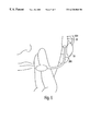
- FIG. 6 illustrates the headset 600 of the present invention, positioned over the wearer's ear.
- the earpiece 20 rests over the ear while the speaker module 30 rests over the pinna of the ear, with the speaker cushion 380 resting against the pinna.
Abstract
Description
Claims (20)
Priority Applications (1)
| Application Number | Priority Date | Filing Date | Title |
|---|---|---|---|
| US09/405,486 US6320960B1 (en) | 1998-09-25 | 1999-09-24 | Headset with adjustable earpiece |
Applications Claiming Priority (2)
| Application Number | Priority Date | Filing Date | Title |
|---|---|---|---|
| US10183898P | 1998-09-25 | 1998-09-25 | |
| US09/405,486 US6320960B1 (en) | 1998-09-25 | 1999-09-24 | Headset with adjustable earpiece |
Publications (1)
| Publication Number | Publication Date |
|---|---|
| US6320960B1 true US6320960B1 (en) | 2001-11-20 |
Family
ID=22286677
Family Applications (1)
| Application Number | Title | Priority Date | Filing Date |
|---|---|---|---|
| US09/405,486 Expired - Lifetime US6320960B1 (en) | 1998-09-25 | 1999-09-24 | Headset with adjustable earpiece |
Country Status (3)
| Country | Link |
|---|---|
| US (1) | US6320960B1 (en) |
| GB (1) | GB2356520B (en) |
| WO (1) | WO2000019685A1 (en) |
Cited By (25)
| Publication number | Priority date | Publication date | Assignee | Title |
|---|---|---|---|---|
| USD468722S1 (en) | 2001-12-24 | 2003-01-14 | Hello Direct, Inc. | Headset with moveable earphones |
| US20030114201A1 (en) * | 2001-12-18 | 2003-06-19 | Inktec Co., Ltd. | Over-the-ear type headset |
| US20040041929A1 (en) * | 2002-09-03 | 2004-03-04 | Marie Lapalme | Headset for camera |
| US20040141628A1 (en) * | 2003-01-17 | 2004-07-22 | Fellowes, Inc. | Earpiece with interchangeable end portion |
| US6775390B1 (en) | 2001-12-24 | 2004-08-10 | Hello Direct, Inc. | Headset with movable earphones |
| US20040165720A1 (en) * | 2003-01-09 | 2004-08-26 | Mary Paulson | Two-way voice communication device having external acoustic noise reduction |
| US20050153748A1 (en) * | 2004-01-08 | 2005-07-14 | Fellowes, Inc. | Headset with variable gain based on position of microphone boom |
| US20060239446A1 (en) * | 2005-04-20 | 2006-10-26 | Gunter David C | Headwear apparatus |
| US20080002835A1 (en) * | 2006-06-30 | 2008-01-03 | Roman Sapiejewski | Earphones |
| US20080152162A1 (en) * | 2006-06-30 | 2008-06-26 | Pericles Nicholas Bakalos | Passive Headphone Equalizing |
| WO2008112302A1 (en) * | 2007-03-14 | 2008-09-18 | Joby, Inc. | Wireless headset with microphone boom with new bending properties |
| US20090214073A1 (en) * | 2008-02-25 | 2009-08-27 | Sony Ericsson Mobile Communications Ab | Adjustable Ear-Hook Earphone with Compressible Inner Portion and Related Methods |
| US20100014699A1 (en) * | 2008-06-18 | 2010-01-21 | Anderson John F | Reversible headset |
| WO2010030240A1 (en) * | 2008-09-09 | 2010-03-18 | Creative Technology Ltd | Ear hook headphones |
| US8670586B1 (en) | 2012-09-07 | 2014-03-11 | Bose Corporation | Combining and waterproofing headphone port exits |
| US20140081098A1 (en) * | 2012-09-14 | 2014-03-20 | Nellcor Puritan Bennett Llc | Sensor system |
| US9215522B2 (en) | 2006-06-30 | 2015-12-15 | Bose Corporation | Earphones |
| US9301040B2 (en) | 2014-03-14 | 2016-03-29 | Bose Corporation | Pressure equalization in earphones |
| USD756972S1 (en) * | 2014-10-21 | 2016-05-24 | Lg Electronics Inc. | Wireless headset |
| USD756971S1 (en) * | 2014-10-21 | 2016-05-24 | Lg Electronics Inc. | Wireless headset |
| US9807493B1 (en) | 2016-04-21 | 2017-10-31 | Human, Incorporated | Attachment apparatus |
| WO2018055481A1 (en) * | 2016-09-22 | 2018-03-29 | Cochlear Limited | Coupling apparatuses for transcutaneous bone conduction devices |
| USD836600S1 (en) * | 2017-09-11 | 2018-12-25 | Kingston Digital, Inc. | Headset |
| USD845928S1 (en) * | 2017-03-14 | 2019-04-16 | Kingston Digital, Inc. | Headset |
| USD933042S1 (en) * | 2019-12-10 | 2021-10-12 | Dongsheng Xiao | Wireless headset microphone |
Families Citing this family (4)
| Publication number | Priority date | Publication date | Assignee | Title |
|---|---|---|---|---|
| EP1290911B1 (en) * | 2000-05-25 | 2006-03-08 | Gn Netcom A/S | Acoustic transmission connection, headset with acoustic transmission connection, and uses of the acoustic transmission connection |
| GB2373125A (en) * | 2000-12-11 | 2002-09-11 | Toong In Electronic Corp | Collapsable earphone and microphone combination |
| US7123737B2 (en) | 2002-02-13 | 2006-10-17 | Plantronics, Inc. | Ear clasp headset |
| TWM256036U (en) * | 2004-03-22 | 2005-01-21 | Global Target Entpr Inc | Adjustable bluetooth wireless earphone |
Citations (88)
| Publication number | Priority date | Publication date | Assignee | Title |
|---|---|---|---|---|
| US844299A (en) | 1906-05-12 | 1907-02-12 | James R Challen | Attachment for telephone-receivers. |
| US1489978A (en) | 1922-08-03 | 1924-04-08 | Byron Oscar | Sound-receiver earpiece |
| US1624144A (en) | 1925-02-16 | 1927-04-12 | Harry J Mathieu | Sound-receiving earpiece |
| US1846231A (en) | 1932-02-23 | Kate busman | ||
| US2353070A (en) | 1943-03-22 | 1944-07-04 | Jr Roy S Pitkin | Headphone |
| US2964596A (en) | 1956-08-01 | 1960-12-13 | Zenith Radio Corp | Sound-reproducing device |
| US4020297A (en) | 1976-01-15 | 1977-04-26 | Brodie S Dan | Adjustable headset |
| US4273969A (en) | 1979-06-01 | 1981-06-16 | Roanwell Corporation | Communications headset mountable over the ear |
| USD263043S (en) | 1980-01-23 | 1982-02-16 | Doris J. Leeds | Headset for one-way private channel radio communications system |
| US4335281A (en) | 1980-06-24 | 1982-06-15 | Plantronics, Inc. | Post-auricle contoured headset for two-way voice communication |
| US4403120A (en) | 1980-06-30 | 1983-09-06 | Pioneer Electronic Corporation | Earphone |
| US4417104A (en) | 1981-08-14 | 1983-11-22 | Viennatone Gesellschaft M.B.H. | Plug for miniature receiver |
| US4484029A (en) | 1983-08-29 | 1984-11-20 | Kenney David S | Cordless telephone switch and line selector |
| US4572324A (en) | 1983-05-26 | 1986-02-25 | Akg Akustische U.Kino-Gerate Gesellschaft Mbh | Ear piece construction |
| USD291197S (en) | 1985-01-14 | 1987-08-04 | Lalanne Claude | Headset or similar article |
| US4689822A (en) | 1986-01-29 | 1987-08-25 | Houng Huang Chiang | Headset |
| US4875233A (en) | 1987-10-16 | 1989-10-17 | Derhaag Robert L | Headset construction and method of making same |
| US4893344A (en) | 1987-09-30 | 1990-01-09 | Gn Netcom A/S | Headset having a post auricle mount and arranged to be worn on a person's outer ear |
| US4917504A (en) | 1989-05-05 | 1990-04-17 | Plantronics, Inc. | Communications headset |
| US4972492A (en) | 1988-03-15 | 1990-11-20 | Kabushiki Kaisha Toshiba | Earphone |
| US4972468A (en) | 1987-10-14 | 1990-11-20 | Sanshin Kogyo Kabushiki Kaisha | Transceiver for hanging on an ear |
| USD317610S (en) | 1988-10-07 | 1991-06-18 | Jahnke Nicolette A | Headphone earpiece |
| USD318053S (en) | 1989-08-02 | 1991-07-09 | Acs Communications, Inc. | Headset |
| US5033094A (en) | 1990-06-25 | 1991-07-16 | Hung Huang Chiang | Adjustable headset |
| USD318669S (en) | 1988-10-17 | 1991-07-30 | Sony Corporation | Headphone |
| USD319241S (en) | 1989-04-14 | 1991-08-20 | Sony Corporation | Headphone |
| US5117465A (en) | 1991-03-15 | 1992-05-26 | Unex Corporation | Earphone with adjustable headband with progressively shallow detents |
| USD327888S (en) | 1990-05-09 | 1992-07-14 | Robert Fitzgerald | Cordless telephone headset |
| JPH04319841A (en) | 1991-04-18 | 1992-11-10 | Foster Electric Co Ltd | Ear set |
| USD331059S (en) | 1990-02-28 | 1992-11-17 | Sony Corporation | Headphone |
| USD331057S (en) | 1990-01-11 | 1992-11-17 | Sony Corporation | Headphone |
| USD331408S (en) | 1989-12-29 | 1992-12-01 | U.S. Philips Corporation | Headphone |
| USD333137S (en) | 1991-04-12 | 1993-02-09 | Telex Communications, Inc. | Headset |
| JPH0579855A (en) | 1991-09-19 | 1993-03-30 | Hitachi Ltd | Optical crank angle sensor |
| US5206997A (en) | 1992-04-20 | 1993-05-04 | Cecil Cunningham | Compression-producing tool, usable as a nutcracker |
| US5210792A (en) | 1990-08-13 | 1993-05-11 | Matsushita Electric Industrial Co., Ltd. | Ear-hang type headset |
| USD340722S (en) | 1992-02-13 | 1993-10-26 | Plantronics, Inc. | Universal acoustic telephone handset interface |
| USD344730S (en) | 1992-07-08 | 1994-03-01 | Acs Communications, Inc. | Communications headset |
| USD345162S (en) | 1991-03-09 | 1994-03-15 | Sony Corporation | Headphone |
| USD350354S (en) | 1992-06-16 | 1994-09-06 | Sony Corporation | Headphone |
| USD351958S (en) | 1992-08-14 | 1994-11-01 | Arrow Manufacturing Incorporated | Belt display device |
| USD353379S (en) | 1992-10-20 | 1994-12-13 | Sony Corporation | Earphone |
| US5381486A (en) | 1992-07-08 | 1995-01-10 | Acs Communications, Inc. | Communications headset having a universal joint-mounted microphone boom |
| USD357479S (en) | 1993-12-16 | 1995-04-18 | U.S. Philips Corporation | Earphone |
| US5412736A (en) | 1992-03-23 | 1995-05-02 | Keliiliki; Shawn P. | Personal audio system and earphone for same |
| US5414769A (en) | 1991-10-31 | 1995-05-09 | Acs Communications, Inc. | Articulated headset support |
| USD358391S (en) | 1994-05-31 | 1995-05-16 | Sony Corporation | Headphone |
| USD358388S (en) | 1992-07-13 | 1995-05-16 | Sony Corporation | Headphone |
| US5438626A (en) | 1993-11-24 | 1995-08-01 | Neuman; Bernard | Collapsible hearing device |
| USD361066S (en) | 1994-06-02 | 1995-08-08 | Gn Netcom, Inc. | Headset |
| US5446788A (en) | 1992-09-29 | 1995-08-29 | Unex Corporation | Adjustable telephone headset |
| US5448637A (en) | 1992-10-20 | 1995-09-05 | Pan Communications, Inc. | Two-way communications earset |
| US5450496A (en) | 1993-07-30 | 1995-09-12 | Acs Communications, Inc. | Communications headset having a detachable receiver capsule and cable pivot |
| US5459290A (en) | 1990-08-21 | 1995-10-17 | Sony Corporation | Acoustic transducer and acoustic transducing system |
| USD363487S (en) | 1994-10-17 | 1995-10-24 | Telex Communications, Inc. | Headset ear piece |
| US5469505A (en) | 1992-07-08 | 1995-11-21 | Acs Wireless, Inc. | Communications headset having a ball joint-mounted receiver assembly |
| EP0690654A2 (en) | 1994-06-30 | 1996-01-03 | Peavey Electronics Corp. | Ergonomic ear-mounted headset |
| USD366486S (en) | 1994-10-11 | 1996-01-23 | Telex Communications, Inc. | Headset |
| US5504812A (en) | 1994-10-11 | 1996-04-02 | Motorola, Inc. | Headset for use with a radiotelephone |
| USD368716S (en) | 1995-02-17 | 1996-04-09 | Sony Corporation | Headphone |
| US5528689A (en) | 1994-11-07 | 1996-06-18 | Chan; Alex Y. | Telephone headset adaptor including a hearing sound tube, a speaking sound tube, a headset, a telephone ear cup and a telephone mouth cup |
| USD371133S (en) | 1994-12-21 | 1996-06-25 | Andrea Electronics Corporation | Boom microphone headset |
| USD372473S (en) | 1995-04-17 | 1996-08-06 | Plantronics, Inc. | Base for cordless remote for communications headset |
| USD372480S (en) | 1995-04-17 | 1996-08-06 | Plantronics, Inc. | Cordless remote for headset |
| US5551090A (en) | 1995-04-20 | 1996-09-03 | Thompson; Janet M. | Ear protecting apparatus |
| USD374011S (en) | 1995-03-17 | 1996-09-24 | Baxter Eric C | Communication aid for bicycle riders |
| USD375313S (en) | 1995-06-13 | 1996-11-05 | Gn Netcom A/S | Headset with adjustable earhook |
| USD375500S (en) | 1995-04-19 | 1996-11-12 | Plantronics, Inc. | Communications headset |
| USD375959S (en) | 1995-04-24 | 1996-11-26 | Plantronics, Inc. | Communications headset |
| US5581622A (en) | 1991-08-29 | 1996-12-03 | Yashima Electric Co., Ltd. | Head set |
| USD376362S (en) | 1995-07-18 | 1996-12-10 | Headphone | |
| USD376598S (en) | 1995-09-13 | 1996-12-17 | Sony Corporation | Headphone combined with microphone |
| USD377020S (en) | 1995-04-19 | 1996-12-31 | Plantronics, Inc. | Communications headset |
| US5590213A (en) | 1995-02-15 | 1996-12-31 | David Clark Company Inc. | Headset with adjustable headpad |
| USD379990S (en) | 1995-04-17 | 1997-06-17 | Plantronics, Inc. | Combined microphone housing and boom assembly |
| US5640458A (en) | 1989-10-25 | 1997-06-17 | Sony Corporation | Audio signal reproducing apparatus |
| USD381336S (en) | 1995-04-19 | 1997-07-22 | Plantronics, Inc. | Communication headset |
| USD381646S (en) | 1995-12-21 | 1997-07-29 | Forte Technologies, Inc. | Headset |
| WO1997027721A1 (en) | 1996-01-26 | 1997-07-31 | Veijo Sakari Makkonen | Headset and method for a headset |
| US5655026A (en) | 1993-12-23 | 1997-08-05 | Otto Engineering, Inc. | Ear receiver |
| USD381987S (en) | 1996-01-16 | 1997-08-05 | Sony Corporation | Headphone |
| USD384958S (en) | 1995-05-09 | 1997-10-14 | Sony Corporation | Earphone with microphone |
| USD385272S (en) | 1996-06-21 | 1997-10-21 | Acs Wireless, Inc. | Communication headset |
| US5694467A (en) | 1996-05-10 | 1997-12-02 | Hewlett Packard Company | Integrated sound/telephone headset system |
| US5757944A (en) | 1995-06-13 | 1998-05-26 | Gn Netcom A/S | Headset with adjustable earhook |
| US5761298A (en) | 1996-05-31 | 1998-06-02 | Plantronics, Inc. | Communications headset with universally adaptable receiver and voice transmitter |
| US5764778A (en) | 1995-06-07 | 1998-06-09 | Sensimetrics Corporation | Hearing aid headset having an array of microphones |
| US5787166A (en) | 1993-11-22 | 1998-07-28 | Ullman; Johan | Telephone communication headset |
Family Cites Families (1)
| Publication number | Priority date | Publication date | Assignee | Title |
|---|---|---|---|---|
| US6427018B1 (en) * | 1997-07-18 | 2002-07-30 | Cotron Corporation | Adjustable earphones for personal audio and communication systems |
-
1999
- 1999-09-24 GB GB0103140A patent/GB2356520B/en not_active Expired - Fee Related
- 1999-09-24 US US09/405,486 patent/US6320960B1/en not_active Expired - Lifetime
- 1999-09-24 WO PCT/US1999/022239 patent/WO2000019685A1/en active Search and Examination
Patent Citations (89)
| Publication number | Priority date | Publication date | Assignee | Title |
|---|---|---|---|---|
| US1846231A (en) | 1932-02-23 | Kate busman | ||
| US844299A (en) | 1906-05-12 | 1907-02-12 | James R Challen | Attachment for telephone-receivers. |
| US1489978A (en) | 1922-08-03 | 1924-04-08 | Byron Oscar | Sound-receiver earpiece |
| US1624144A (en) | 1925-02-16 | 1927-04-12 | Harry J Mathieu | Sound-receiving earpiece |
| US2353070A (en) | 1943-03-22 | 1944-07-04 | Jr Roy S Pitkin | Headphone |
| US2964596A (en) | 1956-08-01 | 1960-12-13 | Zenith Radio Corp | Sound-reproducing device |
| US4020297A (en) | 1976-01-15 | 1977-04-26 | Brodie S Dan | Adjustable headset |
| US4273969A (en) | 1979-06-01 | 1981-06-16 | Roanwell Corporation | Communications headset mountable over the ear |
| USD263043S (en) | 1980-01-23 | 1982-02-16 | Doris J. Leeds | Headset for one-way private channel radio communications system |
| US4335281A (en) | 1980-06-24 | 1982-06-15 | Plantronics, Inc. | Post-auricle contoured headset for two-way voice communication |
| US4403120A (en) | 1980-06-30 | 1983-09-06 | Pioneer Electronic Corporation | Earphone |
| US4417104A (en) | 1981-08-14 | 1983-11-22 | Viennatone Gesellschaft M.B.H. | Plug for miniature receiver |
| US4572324A (en) | 1983-05-26 | 1986-02-25 | Akg Akustische U.Kino-Gerate Gesellschaft Mbh | Ear piece construction |
| US4484029A (en) | 1983-08-29 | 1984-11-20 | Kenney David S | Cordless telephone switch and line selector |
| USD291197S (en) | 1985-01-14 | 1987-08-04 | Lalanne Claude | Headset or similar article |
| US4689822A (en) | 1986-01-29 | 1987-08-25 | Houng Huang Chiang | Headset |
| US4893344A (en) | 1987-09-30 | 1990-01-09 | Gn Netcom A/S | Headset having a post auricle mount and arranged to be worn on a person's outer ear |
| US4972468A (en) | 1987-10-14 | 1990-11-20 | Sanshin Kogyo Kabushiki Kaisha | Transceiver for hanging on an ear |
| US4875233A (en) | 1987-10-16 | 1989-10-17 | Derhaag Robert L | Headset construction and method of making same |
| US4972492A (en) | 1988-03-15 | 1990-11-20 | Kabushiki Kaisha Toshiba | Earphone |
| USD317610S (en) | 1988-10-07 | 1991-06-18 | Jahnke Nicolette A | Headphone earpiece |
| USD318669S (en) | 1988-10-17 | 1991-07-30 | Sony Corporation | Headphone |
| USD319241S (en) | 1989-04-14 | 1991-08-20 | Sony Corporation | Headphone |
| US4917504A (en) | 1989-05-05 | 1990-04-17 | Plantronics, Inc. | Communications headset |
| USD318053S (en) | 1989-08-02 | 1991-07-09 | Acs Communications, Inc. | Headset |
| US5640458A (en) | 1989-10-25 | 1997-06-17 | Sony Corporation | Audio signal reproducing apparatus |
| USD331408S (en) | 1989-12-29 | 1992-12-01 | U.S. Philips Corporation | Headphone |
| USD331057S (en) | 1990-01-11 | 1992-11-17 | Sony Corporation | Headphone |
| USD331059S (en) | 1990-02-28 | 1992-11-17 | Sony Corporation | Headphone |
| USD327888S (en) | 1990-05-09 | 1992-07-14 | Robert Fitzgerald | Cordless telephone headset |
| US5033094A (en) | 1990-06-25 | 1991-07-16 | Hung Huang Chiang | Adjustable headset |
| US5210792A (en) | 1990-08-13 | 1993-05-11 | Matsushita Electric Industrial Co., Ltd. | Ear-hang type headset |
| US5459290A (en) | 1990-08-21 | 1995-10-17 | Sony Corporation | Acoustic transducer and acoustic transducing system |
| USD345162S (en) | 1991-03-09 | 1994-03-15 | Sony Corporation | Headphone |
| US5117465A (en) | 1991-03-15 | 1992-05-26 | Unex Corporation | Earphone with adjustable headband with progressively shallow detents |
| USD333137S (en) | 1991-04-12 | 1993-02-09 | Telex Communications, Inc. | Headset |
| JPH04319841A (en) | 1991-04-18 | 1992-11-10 | Foster Electric Co Ltd | Ear set |
| US5581622A (en) | 1991-08-29 | 1996-12-03 | Yashima Electric Co., Ltd. | Head set |
| JPH0579855A (en) | 1991-09-19 | 1993-03-30 | Hitachi Ltd | Optical crank angle sensor |
| US5533122A (en) | 1991-10-31 | 1996-07-02 | Acs Wireless, Inc. | Articulated headset support |
| US5414769A (en) | 1991-10-31 | 1995-05-09 | Acs Communications, Inc. | Articulated headset support |
| USD340722S (en) | 1992-02-13 | 1993-10-26 | Plantronics, Inc. | Universal acoustic telephone handset interface |
| US5412736A (en) | 1992-03-23 | 1995-05-02 | Keliiliki; Shawn P. | Personal audio system and earphone for same |
| US5206997A (en) | 1992-04-20 | 1993-05-04 | Cecil Cunningham | Compression-producing tool, usable as a nutcracker |
| USD350354S (en) | 1992-06-16 | 1994-09-06 | Sony Corporation | Headphone |
| US5469505A (en) | 1992-07-08 | 1995-11-21 | Acs Wireless, Inc. | Communications headset having a ball joint-mounted receiver assembly |
| US5381486A (en) | 1992-07-08 | 1995-01-10 | Acs Communications, Inc. | Communications headset having a universal joint-mounted microphone boom |
| USD344730S (en) | 1992-07-08 | 1994-03-01 | Acs Communications, Inc. | Communications headset |
| USD358388S (en) | 1992-07-13 | 1995-05-16 | Sony Corporation | Headphone |
| USD351958S (en) | 1992-08-14 | 1994-11-01 | Arrow Manufacturing Incorporated | Belt display device |
| US5446788A (en) | 1992-09-29 | 1995-08-29 | Unex Corporation | Adjustable telephone headset |
| USD353379S (en) | 1992-10-20 | 1994-12-13 | Sony Corporation | Earphone |
| US5448637A (en) | 1992-10-20 | 1995-09-05 | Pan Communications, Inc. | Two-way communications earset |
| US5450496A (en) | 1993-07-30 | 1995-09-12 | Acs Communications, Inc. | Communications headset having a detachable receiver capsule and cable pivot |
| US5787166A (en) | 1993-11-22 | 1998-07-28 | Ullman; Johan | Telephone communication headset |
| US5438626A (en) | 1993-11-24 | 1995-08-01 | Neuman; Bernard | Collapsible hearing device |
| USD357479S (en) | 1993-12-16 | 1995-04-18 | U.S. Philips Corporation | Earphone |
| US5655026A (en) | 1993-12-23 | 1997-08-05 | Otto Engineering, Inc. | Ear receiver |
| USD358391S (en) | 1994-05-31 | 1995-05-16 | Sony Corporation | Headphone |
| USD361066S (en) | 1994-06-02 | 1995-08-08 | Gn Netcom, Inc. | Headset |
| EP0690654A2 (en) | 1994-06-30 | 1996-01-03 | Peavey Electronics Corp. | Ergonomic ear-mounted headset |
| USD366486S (en) | 1994-10-11 | 1996-01-23 | Telex Communications, Inc. | Headset |
| US5504812A (en) | 1994-10-11 | 1996-04-02 | Motorola, Inc. | Headset for use with a radiotelephone |
| USD363487S (en) | 1994-10-17 | 1995-10-24 | Telex Communications, Inc. | Headset ear piece |
| US5528689A (en) | 1994-11-07 | 1996-06-18 | Chan; Alex Y. | Telephone headset adaptor including a hearing sound tube, a speaking sound tube, a headset, a telephone ear cup and a telephone mouth cup |
| USD371133S (en) | 1994-12-21 | 1996-06-25 | Andrea Electronics Corporation | Boom microphone headset |
| US5590213A (en) | 1995-02-15 | 1996-12-31 | David Clark Company Inc. | Headset with adjustable headpad |
| USD368716S (en) | 1995-02-17 | 1996-04-09 | Sony Corporation | Headphone |
| USD374011S (en) | 1995-03-17 | 1996-09-24 | Baxter Eric C | Communication aid for bicycle riders |
| USD372473S (en) | 1995-04-17 | 1996-08-06 | Plantronics, Inc. | Base for cordless remote for communications headset |
| USD372480S (en) | 1995-04-17 | 1996-08-06 | Plantronics, Inc. | Cordless remote for headset |
| USD379990S (en) | 1995-04-17 | 1997-06-17 | Plantronics, Inc. | Combined microphone housing and boom assembly |
| USD381336S (en) | 1995-04-19 | 1997-07-22 | Plantronics, Inc. | Communication headset |
| USD377020S (en) | 1995-04-19 | 1996-12-31 | Plantronics, Inc. | Communications headset |
| USD375500S (en) | 1995-04-19 | 1996-11-12 | Plantronics, Inc. | Communications headset |
| US5551090A (en) | 1995-04-20 | 1996-09-03 | Thompson; Janet M. | Ear protecting apparatus |
| USD375959S (en) | 1995-04-24 | 1996-11-26 | Plantronics, Inc. | Communications headset |
| USD384958S (en) | 1995-05-09 | 1997-10-14 | Sony Corporation | Earphone with microphone |
| US5764778A (en) | 1995-06-07 | 1998-06-09 | Sensimetrics Corporation | Hearing aid headset having an array of microphones |
| USD375313S (en) | 1995-06-13 | 1996-11-05 | Gn Netcom A/S | Headset with adjustable earhook |
| US5757944A (en) | 1995-06-13 | 1998-05-26 | Gn Netcom A/S | Headset with adjustable earhook |
| USD376362S (en) | 1995-07-18 | 1996-12-10 | Headphone | |
| USD376598S (en) | 1995-09-13 | 1996-12-17 | Sony Corporation | Headphone combined with microphone |
| USD381646S (en) | 1995-12-21 | 1997-07-29 | Forte Technologies, Inc. | Headset |
| USD381987S (en) | 1996-01-16 | 1997-08-05 | Sony Corporation | Headphone |
| WO1997027721A1 (en) | 1996-01-26 | 1997-07-31 | Veijo Sakari Makkonen | Headset and method for a headset |
| US5694467A (en) | 1996-05-10 | 1997-12-02 | Hewlett Packard Company | Integrated sound/telephone headset system |
| US5761298A (en) | 1996-05-31 | 1998-06-02 | Plantronics, Inc. | Communications headset with universally adaptable receiver and voice transmitter |
| USD385272S (en) | 1996-06-21 | 1997-10-21 | Acs Wireless, Inc. | Communication headset |
Cited By (35)
| Publication number | Priority date | Publication date | Assignee | Title |
|---|---|---|---|---|
| US20030114201A1 (en) * | 2001-12-18 | 2003-06-19 | Inktec Co., Ltd. | Over-the-ear type headset |
| US6775390B1 (en) | 2001-12-24 | 2004-08-10 | Hello Direct, Inc. | Headset with movable earphones |
| USD468722S1 (en) | 2001-12-24 | 2003-01-14 | Hello Direct, Inc. | Headset with moveable earphones |
| US20040041929A1 (en) * | 2002-09-03 | 2004-03-04 | Marie Lapalme | Headset for camera |
| US7209177B2 (en) | 2002-09-03 | 2007-04-24 | Audisoft | Headset for camera |
| US7551940B2 (en) * | 2003-01-09 | 2009-06-23 | Etymotic Research, Inc. | Two-way voice communication device having external acoustic noise reduction |
| US20040165720A1 (en) * | 2003-01-09 | 2004-08-26 | Mary Paulson | Two-way voice communication device having external acoustic noise reduction |
| US20040141628A1 (en) * | 2003-01-17 | 2004-07-22 | Fellowes, Inc. | Earpiece with interchangeable end portion |
| US20050153748A1 (en) * | 2004-01-08 | 2005-07-14 | Fellowes, Inc. | Headset with variable gain based on position of microphone boom |
| US7089042B2 (en) | 2004-01-08 | 2006-08-08 | Fellowes, Inc. | Headset with variable gain based on position of microphone boom |
| US20060239446A1 (en) * | 2005-04-20 | 2006-10-26 | Gunter David C | Headwear apparatus |
| US20080002835A1 (en) * | 2006-06-30 | 2008-01-03 | Roman Sapiejewski | Earphones |
| US20080152162A1 (en) * | 2006-06-30 | 2008-06-26 | Pericles Nicholas Bakalos | Passive Headphone Equalizing |
| US9215522B2 (en) | 2006-06-30 | 2015-12-15 | Bose Corporation | Earphones |
| US10327062B2 (en) | 2006-06-30 | 2019-06-18 | Bose Corporation | Earphones |
| US7916888B2 (en) | 2006-06-30 | 2011-03-29 | Bose Corporation | In-ear headphones |
| US8073181B2 (en) | 2006-06-30 | 2011-12-06 | Bose Corporation | Passive headphone equalizing |
| WO2008112302A1 (en) * | 2007-03-14 | 2008-09-18 | Joby, Inc. | Wireless headset with microphone boom with new bending properties |
| US20090214073A1 (en) * | 2008-02-25 | 2009-08-27 | Sony Ericsson Mobile Communications Ab | Adjustable Ear-Hook Earphone with Compressible Inner Portion and Related Methods |
| WO2009106151A1 (en) * | 2008-02-25 | 2009-09-03 | Sony Ericsson Mobile Communications Ab | Adjustable ear-hook earphone with compressible inner portion and related methods |
| US20100014699A1 (en) * | 2008-06-18 | 2010-01-21 | Anderson John F | Reversible headset |
| WO2010030240A1 (en) * | 2008-09-09 | 2010-03-18 | Creative Technology Ltd | Ear hook headphones |
| US8670586B1 (en) | 2012-09-07 | 2014-03-11 | Bose Corporation | Combining and waterproofing headphone port exits |
| US20140081098A1 (en) * | 2012-09-14 | 2014-03-20 | Nellcor Puritan Bennett Llc | Sensor system |
| US9301040B2 (en) | 2014-03-14 | 2016-03-29 | Bose Corporation | Pressure equalization in earphones |
| USD756972S1 (en) * | 2014-10-21 | 2016-05-24 | Lg Electronics Inc. | Wireless headset |
| USD756971S1 (en) * | 2014-10-21 | 2016-05-24 | Lg Electronics Inc. | Wireless headset |
| US9807493B1 (en) | 2016-04-21 | 2017-10-31 | Human, Incorporated | Attachment apparatus |
| US10382855B2 (en) | 2016-04-21 | 2019-08-13 | Human, Incorporated | Attachment apparatus |
| WO2018055481A1 (en) * | 2016-09-22 | 2018-03-29 | Cochlear Limited | Coupling apparatuses for transcutaneous bone conduction devices |
| US10542351B2 (en) | 2016-09-22 | 2020-01-21 | Cochlear Limited | Coupling apparatuses for transcutaneous bone conduction devices |
| US11252514B2 (en) | 2016-09-22 | 2022-02-15 | Cochlear Limited | Coupling apparatuses for transcutaneous bone conduction devices |
| USD845928S1 (en) * | 2017-03-14 | 2019-04-16 | Kingston Digital, Inc. | Headset |
| USD836600S1 (en) * | 2017-09-11 | 2018-12-25 | Kingston Digital, Inc. | Headset |
| USD933042S1 (en) * | 2019-12-10 | 2021-10-12 | Dongsheng Xiao | Wireless headset microphone |
Also Published As
| Publication number | Publication date |
|---|---|
| GB2356520A (en) | 2001-05-23 |
| GB2356520B (en) | 2003-02-12 |
| WO2000019685A1 (en) | 2000-04-06 |
| GB0103140D0 (en) | 2001-03-28 |
Similar Documents
| Publication | Publication Date | Title |
|---|---|---|
| US6320960B1 (en) | Headset with adjustable earpiece | |
| US10231048B2 (en) | Ergonomic earpiece with attachment mount | |
| KR100231873B1 (en) | Earmolds for two-way communication devices | |
| US10045113B2 (en) | Earpiece positioning and retaining | |
| US8428289B2 (en) | Headphone adaptation and positioning device | |
| EP1003349B1 (en) | Flexible earhook | |
| US10009680B2 (en) | Retaining structure for an earpiece | |
| US6810987B1 (en) | Earbud headset | |
| US6496589B1 (en) | Headset with overmold | |
| US9955249B2 (en) | Earpiece with movable joint | |
| US11653135B2 (en) | Skirt attachment | |
| US10003878B2 (en) | In-the-ear earphone, its variations and methods of wearing the earphone | |
| US9584897B2 (en) | In-the-ear earphone, its variations and methods of wearing the earphone | |
| GB2339106A (en) | Supporting a microphone around the neck of a user | |
| US10687138B2 (en) | Conformable headset earloop for stability and comfort | |
| EP3731536B1 (en) | Auricular structure using skirt attachment | |
| US20130310113A1 (en) | Cheek stabilizer for audio headset | |
| US11297408B2 (en) | In-ear earpiece retaining structure | |
| WO1999017586A1 (en) | Headset apparatus | |
| JPH04177997A (en) | Ear mount type handset |
Legal Events
| Date | Code | Title | Description |
|---|---|---|---|
| AS | Assignment |
Owner name: HELLO DIRECT, INC., CALIFORNIA Free format text: ASSIGNMENT OF ASSIGNORS INTEREST;ASSIGNORS:LATHROP, ROBERT L., III;LUTZINGER, RICHARD J.;OLSON, KENNETH G.;AND OTHERS;REEL/FRAME:010445/0568;SIGNING DATES FROM 19991201 TO 19991209 |
|
| AS | Assignment |
Owner name: HELLO DIRECT, INC., CALIFORNIA Free format text: ASSIGNMENT OF ASSIGNORS INTEREST;ASSIGNOR:SCHMIDT, PETER OTTO;REEL/FRAME:010955/0894 Effective date: 20000524 |
|
| STCF | Information on status: patent grant |
Free format text: PATENTED CASE |
|
| FPAY | Fee payment |
Year of fee payment: 4 |
|
| FPAY | Fee payment |
Year of fee payment: 8 |
|
| FPAY | Fee payment |
Year of fee payment: 12 |
|
| AS | Assignment |
Owner name: GN NETCOM, INC., NEW HAMPSHIRE Free format text: ASSIGNMENT OF ASSIGNORS INTEREST;ASSIGNOR:HELLO DRIECT, INC.;REEL/FRAME:031285/0579 Effective date: 20130205 |