US6324076B1 - Electronic card with shield cover having tabs where each tab engages with recess of corresponding shield cover - Google Patents
Electronic card with shield cover having tabs where each tab engages with recess of corresponding shield cover Download PDFInfo
- Publication number
- US6324076B1 US6324076B1 US09/194,022 US19402299A US6324076B1 US 6324076 B1 US6324076 B1 US 6324076B1 US 19402299 A US19402299 A US 19402299A US 6324076 B1 US6324076 B1 US 6324076B1
- Authority
- US
- United States
- Prior art keywords
- shield
- card
- flange
- tabs
- recess
- Prior art date
- Legal status (The legal status is an assumption and is not a legal conclusion. Google has not performed a legal analysis and makes no representation as to the accuracy of the status listed.)
- Expired - Fee Related
Links
Images


Classifications
-
- H—ELECTRICITY
- H05—ELECTRIC TECHNIQUES NOT OTHERWISE PROVIDED FOR
- H05K—PRINTED CIRCUITS; CASINGS OR CONSTRUCTIONAL DETAILS OF ELECTRIC APPARATUS; MANUFACTURE OF ASSEMBLAGES OF ELECTRICAL COMPONENTS
- H05K5/00—Casings, cabinets or drawers for electric apparatus
- H05K5/02—Details
- H05K5/0256—Details of interchangeable modules or receptacles therefor, e.g. cartridge mechanisms
- H05K5/026—Details of interchangeable modules or receptacles therefor, e.g. cartridge mechanisms having standardized interfaces
- H05K5/0265—Details of interchangeable modules or receptacles therefor, e.g. cartridge mechanisms having standardized interfaces of PCMCIA type
- H05K5/0269—Card housings therefor, e.g. covers, frames, PCB
Definitions
- the present invention relates to electronic cards and more particularly to exterior shells for such cards.
- PCMCIA Personal Computer Memory Card International Association
- the electronic card of the invention comprises a printed circuit board interposed between card shields having edges. Tabs on the edges of one shield engage recesses on the edge of the other shield. Adequate rigidity is thereby provided. Also included is an I/O connector grounded without a separate ground contact and shielded over its length.
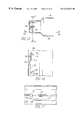
- FIG. 1 is an exploded perspective view of an electronic card of the present invention
- FIG. 2 is a perspective view of the card shown in FIG. 1;
- FIG. 3 is an enlarged view of the area in circle III in FIG. 1;
- FIGS. 4 a - 4 h are schematic illustrations of various ways in which the tabs and recesses in the card illustrated in FIG. 1 may be engaged within the scope of the present invention
- FIGS. 5 a and 5 b are respectively an exploded perspective view of an I/O connector used in the card shown in FIG. 1 and its accompanying universal grounding part and the I/O connector in which its universal grounding part is engaged;
- FIGS. 6 a and 6 b are respectively an exploded view of an alternate I/O connector and a view of the alternate I/O connector in which its grounding part is engaged;
- FIG. 7 is an exploded perspective view of an alternate shielded I/O receptacle
- FIG. 8 is a perspective view of an alternate shield member which may be used with the I/O receptacle shown in FIG. 7;
- FIG. 9 is an exploded perspective view of an alternate preferred embodiment of the card of the present invention.
- FIG. 10 is a bottom perspective view of the card of FIG. 9;
- FIG. 11 is a top perspective view of a card shield used in the card shown in FIG. 9;
- FIG. 12 is a detailed view of the area within circle XII in FIG. 11;
- FIG. 13 is a detailed view of the area with circle XIII in FIG. 11;
- FIG. 14 is a detailed view of the I/O connector used in the card connector shown in FIG. 9;
- FIG. 15 is a cross sectional view through an engaged latch
- FIG. 16 is a cross section through XVII—XVII in FIG. 16;
- FIG. 17 is a cross section through XVIII—XVIII in FIG. 16 .
- FIG. 18 is a top plan view of a shield used in another preferred embodiment of the card of the present invention.
- FIG. 19 is a side elevational view of the shield shown in FIG. 18;
- FIG. 20 is an end view of the shield shown in FIG. 18;
- FIG. 21 is an end view of the entire card which makes use of the shield shown in FIG. 18;
- FIG. 22 is a top plan view of a shield used in another preferred embodiment of the card of the present invention.
- FIG. 23 is a side elevational view of the shield shown in FIG. 22;
- FIG. 24 is an end view of the shield shown in FIG. 22;
- FIG. 25 is a top plan view of a shield used in another preferred embodiment of the card of the present invention.
- FIG. 26 is a side elevational view of the shield shown in FIG. 22;
- FIG. 27 is an end view of the shield shown in FIG. 22;
- FIG. 28 is a partial perspective view of the shield shown in FIG. 18;
- FIG. 29 is an enlarged view of the area within circle XXIX in FIG. 28;
- FIG. 30 is a blank from which the shield shown in FIG. 18 may be manufactured.
- FIG. 31 is an enlarged view of the area within circle XXXI in FIG. 30.
- the PCB assembly consists of the metallized receptacle I/O connector 1 at one end and the 68 pos MTB (MICRO TRIBEAMTM receptacle connector 2 at the other end of the board.
- This connector 2 has the two coding keys 3 and 4 integrated to sides of the plastic housing, simultaneously an upstanding ridge 5 on the top and bottom of this housing.
- the I/O receptacle is described in detail hereafter.
- the top and bottom card shields 7 and 8 are identical stampings of sheet metal eg. stainless steel. Over a substantial length of the shield, at one side are preferably periodically spaced, i.e. at 3 mm intervals, located upstanding tabs 9 , and on the other side at same locations and, periodicity appropriate recesses 10 .
- at the front side 13 of a shield are located two fixation tabs 11 , while at the rear side of each shield are extension portions 12 which are perpendicularly bent to be flush with in front of the metal shield of the connector plug opening of I/O connector 1 . Such a perpendicular bend results in an improved aesthetics and also prevents an opening between I/O connector and shield and prevents what is known as a “smile” effect of the card while allowing for proper axial positioning of the PCB assembly.
- latch 9 a either centrally located or formed on one end of the tab, by a sheared portion, latches the tab in the recess when fully mated.
- the objective of the latching arrangements is to withstand the mechanical forces and hold the assembly intact.
- Another object is to present substantially flat metal sides of card assembly to allow appropriate contact with a ground contact of equipment slot (not shown) which the PCMCIA card needs to fit.
- the I/O connector is shown in FIGS. 5 a and 5 b in which it is shown that plastic is removed at ends of the top and bottom plastic walls 20 to allow the entry from the rear (PCB side) of two metal springs with legs 21 and 22 having inwardly projecting latches 23 and 24 and ends 25 and 26 .
- the latches 23 and 24 contact the metal shield plug connector 18 of assembled I/O plug connector while the ends 25 and 26 are pressed on metal upper and lower shields 7 and 8 to complete the total ground connection of system.
- These two metal spring members are connected to the ground track on the PCB at two connector ends by rivets, as in initial design.
- FIGS. 6 a - 6 b another embodiment is shown in which one metal piece is inserted over for the top and bottom plastic walls of receptacle I/O connector.
- the advantage in this arrangement being not only, is one part needed, but that the metal shield extends over the total length of the connector while ensuring there is no potential drop between the two ground locations situated at connector ends.
- the inward projecting latches 23 and 24 face the central plastic insert 13 to finally connect with mating plug I/O shield 18 .
- the outward latches 27 of the other side of the I/O connector contact the upper and lower shields 7 and 8 , while the edges 25 and 26 are located also against the edges of the card shields.
- FIGS. 7-8 a further development of the I/O receptacle shield in combination with the substitute for ground contact 7 in initial design, is shown.
- the upper and shield portions are shown as two separate half's, each with symmetrical segments of latch retaining openings 12 facing towards each other.
- This design alternative is not only present a metal plate with latch retaining openings, but also present at the rear end 28 of the receptacle I/O, besides the area needed for SMT legs of terminals, a metal wall over the remaining width of the card.
- FIG. 4 showing the rear from the PCB side view of the receptacle I/O.
- This rear end 28 (FIG. 8) in this design when locked above a similar wall extending from lower shield portion, then affords a means for EMC/ESD shielding between the PCB electronics circuit I/O connector on this side of the card assembly.
- the PCB assembly includes the metallized receptacle I/O connector 101 at one end and the 68 pos MTB receptacle connector 102 at the other end of the board.
- This MTB connector 102 has the two coding keys 103 and 104 integrated to sides of the plastic housing, simultaneously an upstanding ridge 105 on the top and bottom of this housing.
- top and bottom surfaces are also located on the I/O connector ends and two recesses 106 .
- the I/O receptacle is described in detail hereafter.
- the top and bottom card shields 107 and 108 are sheet metal e.g. stainless steel. Over a substantial length of the shield, at one side are periodically located, e.g. once every 3 mm, upstanding tabs 109 , and on the other side at same locations and periodicity are appropriate recesses 110 .
- a fixation tab 111 at the front side 113 of a shield is located a fixation tab 111 , and at the rear side of the shield are extension portions 112 which are perpendicularly bent to be flush with in front of the metal shield of the connector plug opening of I/O connector 101 in the final card assembly condition. Such a perpendicular bend results in an improved aesthetics of the card while allowing for proper longitudinal axial positioning of the PCB assembly.
- the tabs 109 cooperate with recess 110 along side and fixation tabs 111 cooperate with oppositely positioned recess 144 on the opposite side of the top shield through slot 100 ., to obtain a final card assembly.
- FIGS. 9-10 and 14 a further development of the I/O receptacle shield in combination with the substitute for ground contact 107 in initial design, is shown.
- the upper and shield portions are shown as two separate half's each with symmetrical segments of latch retaining openings 112 facing towards each other.
- This design is not only present at a metal plate with latch retaining openings, but also present at the rear end 128 of the receptacle I/O, besides the area needed for SMT legs of terminals, a metal wall over the remaining width of the card.
- FIG. 11 and 12 shows modified forms of securing tabs wherein the tabs 109 comprise an upstanding arcuate section 130 having opposed rigid sides 131 and chamfers 132 from which a spring latch 133 extends downwardly and outwardly.
- the recesses 110 are formed in a ledge 134 .
- the ends of the recesses 110 have edges 135 and 136 which are angled inwardly to points 138 .
- the tab 133 engages the underside of ledges 134 in the recesses 110 .
- the two card shields of this embodiment are preferably made from 0.2 mm stainless steel and have a number of mechanical snap fit fasteners. After assembling the two shields to each other, these fasteners make the card surprisingly and unexpectantly rigid and stiff against bending and torsion. These fasteners also effect good electrical connection for grounding between the two card shields due to multiple contact points, and also because no intermediate load bearing surfaces are utilized the card is optimally shielded for EMI.
- These fasteners comprise a number of tabs 109 which engage recesses 110 . It will be seen from the drawings (in parts FIGS. 15-16) that each of the tabs 109 and latch 133 are angled inwardly from the perpendicular plane, for example, by angle of (FIG.
- Each tab 109 comprises a spring section 132 integrated with a latch 133 , which hooks in a latch 134 underneath the area of each recess 110 .
- This latch 133 holds the two card shields from opening after assembly. During mating, the tab 109 will be subjected to elastic bending and torsion forces from the tip of latch 133 up both rigid sides.
- Each tab 109 includes also two rigid sides 131 which engage with some play in both ends of the recess 110 .
- the total number of rigid sides 131 and recess ends give the mechanical connection between the two card shields a high shear strength, which results in a high stiffness against bending and torsion.
- the two card shields are identical and are hermaphodite, that is, each shield contains both male and female fastening elements. p As is shown in particular with regard to FIGS. 12-14, during mating the chamfers 132 will first touch the leading edges 135 and 136 so that they will guide the tab 109 to the end position beyond points 138 and guarantee that the latch 133 will hook underneath edge 134 .
- the points 138 function as latches to hold the tab in position in the recess and provide an audible “snap” that indicates proper latching.
- the relative dimensions of the chamfers 132 and ledges 135 and 136 are designed to absorb manufacturing (stamping) tolerances.
- the latch mechanism is designed in a way that there is an initial play between the latch and the ledge 134 in vertical direction, which is taken away by a second spring function of ends 137 of the ledge. As these ends have a bending angle less than 90°, these make first contact when assembling the two card shields and then these have to be pressed together a little before the latch 133 will be mated. After that the latch mechanism has no further play.
- the overall cumulative lengths of the spring like tabs will be at least 10% of the length of the shield and more preferably will be 50% of the length of the shield.
- FIGS. 18-21 an embodiment is shown in which no I/O receptacle is employed. Otherwise this embodiment is generally the same as that described in FIGS. 9-17. That is, it has identical tabs 245 which engage identical recesses 254 , and it also has a space 240 for an MTB connector (not shown). Referring particularly to FIGS. 20-21, it will be noted that the joining tabs and recesses of the rear are disposed to the side and there is centrally adjoining panels 241 and 242 . Referring to FIGS. 22-24, another embodiment is shown which is similar to the foregoing embodiment except that it makes use of a single 15 position I/O connector 343 . The tabs 309 and recesses 310 are the same as was described above. In this embodiment the connecting tabs and recesses 345 and 354 respectively are positioned outwardly adjacent the I/O connector on the front end of the card while tabs 311 and recess 344 cooperate with each other on the MTB connector side.
- FIGS. 25-27 another embodiment is shown which makes use of two I/O connectors 446 and 447 . Otherwise this embodiment is essentially the same as the ones described above. It will be noted that at the rear end of this card the tab and recess 448 are positioned between the I/O connectors and the rear side of the card.
- the full metal corners of the embodiments described above are comprised of a folded metal wall shown generally at 549 .
- this curved corner may be produced from a blank having a medial protrusion 450 and lateral protrusions 451 and 452 which may be folded upwardly and inwardly in segments to produce the desired rounded effect.
- EMI/ESD shielding or similar full metal shielding without use of plastic or open air. This feature is also aesthetically advantageous since it has no sharp edges.
Abstract
Description
Claims (8)
Priority Applications (1)
| Application Number | Priority Date | Filing Date | Title |
|---|---|---|---|
| US09/194,022 US6324076B1 (en) | 1997-05-22 | 1997-05-22 | Electronic card with shield cover having tabs where each tab engages with recess of corresponding shield cover |
Applications Claiming Priority (2)
| Application Number | Priority Date | Filing Date | Title |
|---|---|---|---|
| US09/194,022 US6324076B1 (en) | 1997-05-22 | 1997-05-22 | Electronic card with shield cover having tabs where each tab engages with recess of corresponding shield cover |
| PCT/US1997/008877 WO1997044990A1 (en) | 1996-05-22 | 1997-05-22 | Electronic card with shield cover having tabs where each tab engages with recess of corresponding shield cover |
Publications (1)
| Publication Number | Publication Date |
|---|---|
| US6324076B1 true US6324076B1 (en) | 2001-11-27 |
Family
ID=22715989
Family Applications (1)
| Application Number | Title | Priority Date | Filing Date |
|---|---|---|---|
| US09/194,022 Expired - Fee Related US6324076B1 (en) | 1997-05-22 | 1997-05-22 | Electronic card with shield cover having tabs where each tab engages with recess of corresponding shield cover |
Country Status (1)
| Country | Link |
|---|---|
| US (1) | US6324076B1 (en) |
Cited By (13)
| Publication number | Priority date | Publication date | Assignee | Title |
|---|---|---|---|---|
| US6577506B1 (en) * | 1998-10-27 | 2003-06-10 | Iomega Corporation | Card type electronic device |
| US20030231472A1 (en) * | 2002-06-17 | 2003-12-18 | Tien-Chih Tseng | Assembly structure of electronic card |
| US20040008502A1 (en) * | 2000-07-19 | 2004-01-15 | Frederic Hautier | Pack provided with an antenna extension for electronic card and method for the assembling of the pack |
| EP1408727A2 (en) * | 2002-10-09 | 2004-04-14 | Itt Manufacturing Enterprises, Inc. | A plug-in card for electronic data-processing devices |
| US6809933B2 (en) * | 2000-04-04 | 2004-10-26 | Matsushita Electric Industrial Eo., Ltd. | Printed circuit board holding structure |
| US20040252466A1 (en) * | 2003-06-11 | 2004-12-16 | Jang Bor-Ren | Electrical card |
| US6925708B1 (en) * | 1998-03-02 | 2005-08-09 | Valeo Vision | Method of shielding a printed circuit electronics card mounted on a metal substrate |
| US20060022329A1 (en) * | 2004-08-02 | 2006-02-02 | Peter Jordan | Carrier device for electronic chip |
| WO2007046789A1 (en) * | 2005-10-17 | 2007-04-26 | Duel Systems | Electronic packages for peripheral devices |
| US20080101042A1 (en) * | 2006-10-31 | 2008-05-01 | Broadtek Technology Co., Ltd. | Expansion card |
| US20100276948A1 (en) * | 2009-05-04 | 2010-11-04 | Hong Fu Jin Precision Industry (Shenzhen) Co., Ltd. | Latching device |
| US20160150685A1 (en) * | 2013-07-10 | 2016-05-26 | Kitagawa Industries Co., Ltd. | Electromagnetic shielding structure |
| US20180109023A1 (en) * | 2016-10-17 | 2018-04-19 | Samsung Electronics Co., Ltd. | Printed circuit boards and solid state drives including the same |
Citations (29)
| Publication number | Priority date | Publication date | Assignee | Title |
|---|---|---|---|---|
| US2625723A (en) * | 1951-04-07 | 1953-01-20 | Bassett W E Co | Bendable prong paper fastening clip |
| US4734971A (en) * | 1987-01-12 | 1988-04-05 | Aro Metal Stamping Co., Inc. | Method of mechanically crimping overlapping sheet metal |
| US4872848A (en) | 1987-11-09 | 1989-10-10 | E. I. Du Pont De Nemours And Company | Cover for a multipoint connector |
| JPH0463284A (en) * | 1990-07-02 | 1992-02-28 | Canon Inc | Microwave plasma cvd device |
| US5144533A (en) | 1991-06-27 | 1992-09-01 | Motorola, Inc. | Self-locking housing assembly |
| US5207586A (en) | 1991-10-24 | 1993-05-04 | Intel Corporation | Integral connector system for credit card size I/O card external connector |
| US5330360A (en) | 1992-08-21 | 1994-07-19 | The Whitaker Corporation | Memory card and connector therefor |
| US5339222A (en) | 1993-04-06 | 1994-08-16 | The Whitaker Corporation | Shielded printed circuit card holder |
| US5409385A (en) | 1993-10-07 | 1995-04-25 | Genrife Company Limited | I/O card and connection mechanism thereof |
| US5463531A (en) | 1994-07-05 | 1995-10-31 | Motorola, Inc. | PCMCIA electronics housing |
| US5477426A (en) | 1993-12-15 | 1995-12-19 | Itt Corporation | IC card with board positioning means |
| US5478259A (en) | 1994-03-28 | 1995-12-26 | Burndy Corporation | Card edge connector with combined shielding and voltage drain protection |
| US5493477A (en) | 1993-09-10 | 1996-02-20 | Honda Tsushin Kogyo Kabushiki Kaisha | IC card device |
| US5497297A (en) * | 1994-06-28 | 1996-03-05 | Intel Corporation | Frame and cover structure for integrated circuit cards |
| US5502892A (en) | 1994-07-01 | 1996-04-02 | Maxconn Incorporated | Method of forming a welded encasement for a computer card |
| US5529503A (en) | 1991-12-09 | 1996-06-25 | International Business Machines Corporation | Jacketed circuit card |
| US5548483A (en) * | 1995-01-24 | 1996-08-20 | Elco Corporation | Frameless IC card and housing therefor |
| US5563770A (en) | 1994-02-25 | 1996-10-08 | Itt Corporation | IC card with board positioning means |
| US5564948A (en) | 1993-12-02 | 1996-10-15 | Harting Elektronik Gmbh | Shielded, printed circuit board, plug-in connection |
| US5687064A (en) | 1993-08-31 | 1997-11-11 | Wireless Access, Inc. | Rigidized outer support structure for an integrated circuit card |
| US5689405A (en) | 1996-09-25 | 1997-11-18 | Itt Corporation | IC card rear board support |
| US5754404A (en) | 1996-05-14 | 1998-05-19 | Itt Cannon Gmbh | IC card rear board-connector support |
| US5768110A (en) | 1994-03-01 | 1998-06-16 | Itt Cannon Gmbh | Plug-in card for electronic data processing equipment and a process for its manufacture and assembly |
| US5775946A (en) * | 1996-08-23 | 1998-07-07 | Amphenol Corporation | Shielded multi-port connector and method of assembly |
| US5833473A (en) * | 1997-03-12 | 1998-11-10 | Itt Manufacturing Enterprises, Inc. | Cardbus Bridge |
| US5984731A (en) * | 1997-11-17 | 1999-11-16 | Xircom, Inc. | Removable I/O device with integrated receptacles for receiving standard plugs |
| US6058018A (en) * | 1996-04-05 | 2000-05-02 | Berg Technology, Inc. | Electronic card |
| US6116962A (en) * | 1997-11-17 | 2000-09-12 | Xircom Inc | Type III PCMCIA card with integrated receptacles for receiving standard communications plugs |
| US6160711A (en) * | 1996-04-05 | 2000-12-12 | Berg Technology, Inc. | Electronic card |
-
1997
- 1997-05-22 US US09/194,022 patent/US6324076B1/en not_active Expired - Fee Related
Patent Citations (29)
| Publication number | Priority date | Publication date | Assignee | Title |
|---|---|---|---|---|
| US2625723A (en) * | 1951-04-07 | 1953-01-20 | Bassett W E Co | Bendable prong paper fastening clip |
| US4734971A (en) * | 1987-01-12 | 1988-04-05 | Aro Metal Stamping Co., Inc. | Method of mechanically crimping overlapping sheet metal |
| US4872848A (en) | 1987-11-09 | 1989-10-10 | E. I. Du Pont De Nemours And Company | Cover for a multipoint connector |
| JPH0463284A (en) * | 1990-07-02 | 1992-02-28 | Canon Inc | Microwave plasma cvd device |
| US5144533A (en) | 1991-06-27 | 1992-09-01 | Motorola, Inc. | Self-locking housing assembly |
| US5207586A (en) | 1991-10-24 | 1993-05-04 | Intel Corporation | Integral connector system for credit card size I/O card external connector |
| US5529503A (en) | 1991-12-09 | 1996-06-25 | International Business Machines Corporation | Jacketed circuit card |
| US5330360A (en) | 1992-08-21 | 1994-07-19 | The Whitaker Corporation | Memory card and connector therefor |
| US5339222A (en) | 1993-04-06 | 1994-08-16 | The Whitaker Corporation | Shielded printed circuit card holder |
| US5687064A (en) | 1993-08-31 | 1997-11-11 | Wireless Access, Inc. | Rigidized outer support structure for an integrated circuit card |
| US5493477A (en) | 1993-09-10 | 1996-02-20 | Honda Tsushin Kogyo Kabushiki Kaisha | IC card device |
| US5409385A (en) | 1993-10-07 | 1995-04-25 | Genrife Company Limited | I/O card and connection mechanism thereof |
| US5564948A (en) | 1993-12-02 | 1996-10-15 | Harting Elektronik Gmbh | Shielded, printed circuit board, plug-in connection |
| US5477426A (en) | 1993-12-15 | 1995-12-19 | Itt Corporation | IC card with board positioning means |
| US5563770A (en) | 1994-02-25 | 1996-10-08 | Itt Corporation | IC card with board positioning means |
| US5768110A (en) | 1994-03-01 | 1998-06-16 | Itt Cannon Gmbh | Plug-in card for electronic data processing equipment and a process for its manufacture and assembly |
| US5478259A (en) | 1994-03-28 | 1995-12-26 | Burndy Corporation | Card edge connector with combined shielding and voltage drain protection |
| US5497297A (en) * | 1994-06-28 | 1996-03-05 | Intel Corporation | Frame and cover structure for integrated circuit cards |
| US5502892A (en) | 1994-07-01 | 1996-04-02 | Maxconn Incorporated | Method of forming a welded encasement for a computer card |
| US5463531A (en) | 1994-07-05 | 1995-10-31 | Motorola, Inc. | PCMCIA electronics housing |
| US5548483A (en) * | 1995-01-24 | 1996-08-20 | Elco Corporation | Frameless IC card and housing therefor |
| US6058018A (en) * | 1996-04-05 | 2000-05-02 | Berg Technology, Inc. | Electronic card |
| US6160711A (en) * | 1996-04-05 | 2000-12-12 | Berg Technology, Inc. | Electronic card |
| US5754404A (en) | 1996-05-14 | 1998-05-19 | Itt Cannon Gmbh | IC card rear board-connector support |
| US5775946A (en) * | 1996-08-23 | 1998-07-07 | Amphenol Corporation | Shielded multi-port connector and method of assembly |
| US5689405A (en) | 1996-09-25 | 1997-11-18 | Itt Corporation | IC card rear board support |
| US5833473A (en) * | 1997-03-12 | 1998-11-10 | Itt Manufacturing Enterprises, Inc. | Cardbus Bridge |
| US5984731A (en) * | 1997-11-17 | 1999-11-16 | Xircom, Inc. | Removable I/O device with integrated receptacles for receiving standard plugs |
| US6116962A (en) * | 1997-11-17 | 2000-09-12 | Xircom Inc | Type III PCMCIA card with integrated receptacles for receiving standard communications plugs |
Cited By (22)
| Publication number | Priority date | Publication date | Assignee | Title |
|---|---|---|---|---|
| US6925708B1 (en) * | 1998-03-02 | 2005-08-09 | Valeo Vision | Method of shielding a printed circuit electronics card mounted on a metal substrate |
| US6577506B1 (en) * | 1998-10-27 | 2003-06-10 | Iomega Corporation | Card type electronic device |
| US6809933B2 (en) * | 2000-04-04 | 2004-10-26 | Matsushita Electric Industrial Eo., Ltd. | Printed circuit board holding structure |
| US20040008502A1 (en) * | 2000-07-19 | 2004-01-15 | Frederic Hautier | Pack provided with an antenna extension for electronic card and method for the assembling of the pack |
| US6769621B2 (en) * | 2000-07-19 | 2004-08-03 | Fci | Pack provided with an antenna extension for electronic card and method for the assembling of the pack |
| US20030231472A1 (en) * | 2002-06-17 | 2003-12-18 | Tien-Chih Tseng | Assembly structure of electronic card |
| US7075792B2 (en) * | 2002-06-17 | 2006-07-11 | Longwell Company | Assembly structure of electronic card |
| CN100429675C (en) * | 2002-10-09 | 2008-10-29 | Itt制造企业公司 | Insertion card for electronic data processing device |
| EP1408727A2 (en) * | 2002-10-09 | 2004-04-14 | Itt Manufacturing Enterprises, Inc. | A plug-in card for electronic data-processing devices |
| EP1408727A3 (en) * | 2002-10-09 | 2005-10-19 | Itt Manufacturing Enterprises, Inc. | A plug-in card for electronic data-processing devices |
| US20040070962A1 (en) * | 2002-10-09 | 2004-04-15 | Schremmer Andreas Michael | PC card housing |
| US7082037B2 (en) * | 2002-10-09 | 2006-07-25 | Itt Manufacturing Enterprises, Inc | PC card housing |
| US20040252466A1 (en) * | 2003-06-11 | 2004-12-16 | Jang Bor-Ren | Electrical card |
| US20060022329A1 (en) * | 2004-08-02 | 2006-02-02 | Peter Jordan | Carrier device for electronic chip |
| WO2007046789A1 (en) * | 2005-10-17 | 2007-04-26 | Duel Systems | Electronic packages for peripheral devices |
| US20080101042A1 (en) * | 2006-10-31 | 2008-05-01 | Broadtek Technology Co., Ltd. | Expansion card |
| US7489515B2 (en) * | 2006-10-31 | 2009-02-10 | Broadtek Technology Co., Ltd. | Expansion card |
| US20100276948A1 (en) * | 2009-05-04 | 2010-11-04 | Hong Fu Jin Precision Industry (Shenzhen) Co., Ltd. | Latching device |
| US20160150685A1 (en) * | 2013-07-10 | 2016-05-26 | Kitagawa Industries Co., Ltd. | Electromagnetic shielding structure |
| US9655290B2 (en) * | 2013-07-10 | 2017-05-16 | Kitagawa Industries Co., Ltd. | Electromagnetic shielding structure |
| US20180109023A1 (en) * | 2016-10-17 | 2018-04-19 | Samsung Electronics Co., Ltd. | Printed circuit boards and solid state drives including the same |
| US10320105B2 (en) * | 2016-10-17 | 2019-06-11 | Samsung Electronics Co., Ltd. | Printed circuit boards and solid state drives including the same |
Similar Documents
| Publication | Publication Date | Title |
|---|---|---|
| EP0901744B1 (en) | Electronic card with shield cover having tabs where each tab engages with recess of corresponding shield cover | |
| JP2007193809A (en) | Electronic card | |
| US6324076B1 (en) | Electronic card with shield cover having tabs where each tab engages with recess of corresponding shield cover | |
| US5339222A (en) | Shielded printed circuit card holder | |
| US5846092A (en) | Plastic cased IC card adapter assembly | |
| US5780365A (en) | PC card frame kit and PC card | |
| US6666720B1 (en) | Electrical connector receptacle with module kickout mechanism | |
| DE102008052866B4 (en) | Electrical junction box with an electronic component and electrical connection unit containing such an electrical junction box | |
| US7771236B2 (en) | Electrical connector | |
| US5490043A (en) | Grounding clip structure of I/O card | |
| US5469332A (en) | PC card assembly | |
| KR100701870B1 (en) | Frame kit for ic card and ic card | |
| US20180294602A1 (en) | Connector assembly with an improved latch member having a shorter length | |
| EP1223643A2 (en) | Apparatus for a receiving plug-in module | |
| US6151219A (en) | Electronic card with sheet metal and overmolded plastic frame parts | |
| US5954540A (en) | Shell means for use with mini electrical connector | |
| KR100479397B1 (en) | Electronic card with shield cover having tabs where each tab engages with recess of corresponding shield cover | |
| US20040023549A1 (en) | Combination of device and retainer clip for retaining the device through an open window in panel | |
| EP1717734B1 (en) | Electronic card assembly | |
| EP1029429A2 (en) | Electronic card with rf extension | |
| CN220553652U (en) | Connector, functional module and electronic equipment | |
| US7026546B2 (en) | Printed circuit card kit | |
| JP2001518652A (en) | Electronic card |
Legal Events
| Date | Code | Title | Description |
|---|---|---|---|
| AS | Assignment |
Owner name: BERG TECHNOLOGY, INC., NEVADA Free format text: ASSIGNMENT OF ASSIGNORS INTEREST;ASSIGNORS:GERRITS, ANTONIUS;PIGMANS, PAULUS;ALST, WIM VAN;AND OTHERS;REEL/FRAME:011538/0327;SIGNING DATES FROM 19990702 TO 19990712 |
|
| FPAY | Fee payment |
Year of fee payment: 4 |
|
| AS | Assignment |
Owner name: BANC OF AMERICA SECURITIES LIMITED, AS SECURITY AG Free format text: SECURITY AGREEMENT;ASSIGNOR:FCI AMERICAS TECHNOLOGY, INC.;REEL/FRAME:017400/0192 Effective date: 20060331 |
|
| AS | Assignment |
Owner name: FCI AMERICAS TECHNOLOGY, INC., NEVADA Free format text: CHANGE OF NAME;ASSIGNOR:BERG TECHNOLOGY, INC.;REEL/FRAME:017422/0729 Effective date: 20000808 |
|
| FPAY | Fee payment |
Year of fee payment: 8 |
|
| AS | Assignment |
Owner name: FCI AMERICAS TECHNOLOGY LLC, NEVADA Free format text: CONVERSION TO LLC;ASSIGNOR:FCI AMERICAS TECHNOLOGY, INC.;REEL/FRAME:025957/0432 Effective date: 20090930 |
|
| AS | Assignment |
Owner name: FCI AMERICAS TECHNOLOGY LLC (F/K/A FCI AMERICAS TE Free format text: RELEASE OF PATENT SECURITY INTEREST AT REEL/FRAME NO. 17400/0192;ASSIGNOR:BANC OF AMERICA SECURITIES LIMITED;REEL/FRAME:029377/0632 Effective date: 20121026 |
|
| REMI | Maintenance fee reminder mailed | ||
| LAPS | Lapse for failure to pay maintenance fees | ||
| STCH | Information on status: patent discontinuation |
Free format text: PATENT EXPIRED DUE TO NONPAYMENT OF MAINTENANCE FEES UNDER 37 CFR 1.362 |
|
| FP | Lapsed due to failure to pay maintenance fee |
Effective date: 20131127 |