US6325385B1 - Piston ring - Google Patents
Piston ring Download PDFInfo
- Publication number
- US6325385B1 US6325385B1 US09/352,345 US35234599A US6325385B1 US 6325385 B1 US6325385 B1 US 6325385B1 US 35234599 A US35234599 A US 35234599A US 6325385 B1 US6325385 B1 US 6325385B1
- Authority
- US
- United States
- Prior art keywords
- piston ring
- film
- diamond
- percent
- carbon
- Prior art date
- Legal status (The legal status is an assumption and is not a legal conclusion. Google has not performed a legal analysis and makes no representation as to the accuracy of the status listed.)
- Expired - Lifetime
Links
Images


Classifications
-
- F—MECHANICAL ENGINEERING; LIGHTING; HEATING; WEAPONS; BLASTING
- F16—ENGINEERING ELEMENTS AND UNITS; GENERAL MEASURES FOR PRODUCING AND MAINTAINING EFFECTIVE FUNCTIONING OF MACHINES OR INSTALLATIONS; THERMAL INSULATION IN GENERAL
- F16J—PISTONS; CYLINDERS; SEALINGS
- F16J9/00—Piston-rings, e.g. non-metallic piston-rings, seats therefor; Ring sealings of similar construction
- F16J9/26—Piston-rings, e.g. non-metallic piston-rings, seats therefor; Ring sealings of similar construction characterised by the use of particular materials
-
- Y—GENERAL TAGGING OF NEW TECHNOLOGICAL DEVELOPMENTS; GENERAL TAGGING OF CROSS-SECTIONAL TECHNOLOGIES SPANNING OVER SEVERAL SECTIONS OF THE IPC; TECHNICAL SUBJECTS COVERED BY FORMER USPC CROSS-REFERENCE ART COLLECTIONS [XRACs] AND DIGESTS
- Y10—TECHNICAL SUBJECTS COVERED BY FORMER USPC
- Y10S—TECHNICAL SUBJECTS COVERED BY FORMER USPC CROSS-REFERENCE ART COLLECTIONS [XRACs] AND DIGESTS
- Y10S277/00—Seal for a joint or juncture
- Y10S277/935—Seal made of a particular material
- Y10S277/936—Composite
- Y10S277/938—Carbon or graphite particle or filament
-
- Y—GENERAL TAGGING OF NEW TECHNOLOGICAL DEVELOPMENTS; GENERAL TAGGING OF CROSS-SECTIONAL TECHNOLOGIES SPANNING OVER SEVERAL SECTIONS OF THE IPC; TECHNICAL SUBJECTS COVERED BY FORMER USPC CROSS-REFERENCE ART COLLECTIONS [XRACs] AND DIGESTS
- Y10—TECHNICAL SUBJECTS COVERED BY FORMER USPC
- Y10S—TECHNICAL SUBJECTS COVERED BY FORMER USPC CROSS-REFERENCE ART COLLECTIONS [XRACs] AND DIGESTS
- Y10S277/00—Seal for a joint or juncture
- Y10S277/935—Seal made of a particular material
- Y10S277/943—Ceramic or glass
Definitions
- the present invention relates to a piston ring for use in internal combustion engines.
- piston ring In recent years, engines must meet increased demands for higher output, high revolutions per minute and longer product service life and must also comply with ever stricter exhaust gas emission regulations.
- the piston ring must therefore function in a yet harsher operating environment.
- Many of such piston rings are formed typically with a hard surface treatment layer such as chromium plating film, nitrided layer or physical vapor deposition film on the upper and lower surfaces and the outer circumferential surface.
- piston rings having a nitrided layer or physical vapor deposition film are prone to wear the ring grooves of the aluminum alloy pistons.
- piston rings having nitrided layers are prone to cause aluminum adhesion on the upper and lower surfaces, increasing the wear on the ring grooves.
- break-in between the cylinder and piston ring is not sufficient so that scuffing may occur between the cylinder and piston ring formed with the above mentioned hard surface treatment layer. Accordingly, a method to improve initial break-in characteristics of these hard surface treatment layers or a hard surface treatment layer having both scuffing resistance and wear resistance is needed.
- a film of either 98.0 to 99.5 percent molybdenum or chromium or both and the remainder of nitrogen was formed by physical vapor deposition on a nitrided layer or physical vapor deposition film in order to improve the initial break-in characteristics.
- a TiN film was formed over a hard film comprised of CBN, TiC, Ti (C,N), SiC, diamonds or Al 2 O 3 in order to improve the scuffing resistance.
- a thin film of artificial diamond material was formed on the piston ring and on the top surface, external circumferential surface and ring groove of the piston in order to improve durability.
- a film having amorphous carbon as the main constituent in which tungsten and/or silicon was dispersed was formed on the sliding surface which mates with a sliding surface formed of iron-type material containing ferrite. This technology is utilized for instance, in the hydraulic valve in power steering mechanisms.
- the technology proposed in the above first method has the drawback that the molybdenum or chromium film wears away quickly.
- the technology proposed in the above second method has a TiN film with excessive hardness so that resistance to scuffing is inadequate.
- the technology proposed in the above third method has no detailed description of any kind regarding the thin film of artificial diamond material.
- the technology proposed in the above fourth method provides no description of aluminum adhesion on the upper and lower surfaces of the piston rings mating with aluminum alloy pistons.
- a method is known, for suppressing aluminum adhesion in the initial stages of engine operation by coating the upper and lower surfaces of the piston ring with a synthetic resin film containing solid lubricant.
- this synthetic resin film has poor wear resistance, so this method has the drawback that suppression of the aluminum adhesion does not last long.
- the present invention is a piston ring covered on a sliding surface of the piston ring with a diamond-like carbon film, wherein an under film is formed beneath the diamond-like carbon film and is comprised of one or more elements selected from the group consisting of silicon, titanium, tungsten, chromium, molybdenum, niobium and vanadium in an atomic content of 70 percent or more and below 100 percent, and the remaining content consisting of carbon, or one or more of said elements in an atomic content of 100 percent.
- the diamond-like carbon forming a film of the present invention is configured from any one of the following structures.
- Amorphous carbon structure having partly a diamond structure.
- Amorphous carbon structure having partly a graphite structure having partly a graphite structure.
- the sliding surface is the upper, lower or outer circumferential surfaces of the piston ring.
- the film of the present invention covers at least one surface of the upper, lower and outer circumferential surfaces of the piston ring.
- the sliding surface of the piston ring of the present invention comprises a laminated structure of piston ring base material, under film, and diamond-like carbon film; or a laminated structure of piston ring base material, hard surface treatment layer, under film, and diamond-like carbon film.
- the hard surface treatment layer may be a chromium plating film, a nitrided layer or an ion plating film.
- the resistance to aluminum adhesion, wear resistance and scuffing resistance of the diamond-like carbon film are inherently high, however a film having improved scuffing resistance, improved wear resistance and improved resistance to aluminum adhesion can be obtained by including one or more elements in an atomic content of 5 to 40 percent selected from the group consisting of silicon, titanium, tungsten, chromium, molybdenum, niobium, and vanadium.
- the one or more elements are present as metal or carbides or both.
- the under film is firmly bonded to the piston ring base material or the hard surface treatment layer of any one of chromium plating film, nitrided layer and ion plating film, and also bonded to the diamond-like carbon film.
- the under film simultaneously alleviates strain occurring internally in the diamond-like carbon film.
- the diamond-like carbon film of the present invention has high adhesive strength and is not prone to generate defects such as cracks, film collapse or pits during use.
- the thickness of the under film is preferably within a range of 1 to 35 percent of the sum of the diamond-like carbon film thickness and the under film thickness. When the thickness is below 1 percent, the effect of alleviating strain occurring internally in the diamond-like carbon film can not be achieved. When the thickness exceeds 35 percent, the protective effect of the hard surface treatment layer that protects the diamond-like carbon film from the rear against deformation or loads from the sliding surface side can not be obtained. Further, the scuffing resistance of the under film exposed after wear of the diamond-like carbon film is poor so that the scuffing resistance becomes low.
- the under film of the present invention has a film thickness taking resistance to scuffing into account, and quickly wears away not to deteriorate resistance to scuffing after the diamond-like carbon film has fulfilled its job in the initial break-in period and worn away.
- the hard surface treatment layer consisting of any one of a chromium plating film, a nitrided layer or an ion plating film has a high level of hardness and can protect the diamond-like carbon film from the rear against deformation or loads from the sliding surface side and can keep the piston ring resistant to wear after the diamond-like carbon film and under film have worn away.
- the piston ring of the present invention as explained above, has a diamond-like carbon film with superior adhesive strength and has superior resistance to aluminum adhesion, resistance to scuffing and initial break-in characteristics, and is particularly effective on cylinder bores and piston ring grooves of aluminum alloys.
- FIGS. 1A, 1 B and 1 C are respectively longitudinal cross sectional views of a portion of the piston rings illustrating embodiments of the present invention.
- FIGS. 2A and 2B are respectively longitudinal cross sectional views of a portion of the piston rings illustrating embodiments of the present invention.
- FIG. 3 is a drawing showing a configuration of the microwelding tester.
- FIG. 4 is a graph showing test results from the microwelding tests.
- FIGS. 5A and 5B are drawings showing the structure of the pin-on-cylinder friction testing machine.
- FIG. 5A is a front view partly in cross section.
- FIG. 5B is a side view.
- FIGS. 1A through 1C and FIGS. 2A through 2B are explained while referring to FIGS. 1A through 1C and FIGS. 2A through 2B.
- a piston ring 1 is formed over the entire surface with a gas nitrided layer 2 in a thickness of 5 to 150 micrometers.
- a diamond-like carbon film 4 containing one or more elements in an atomic content of 5 to 40 percent selected from the group consisting of silicon, titanium, tungsten, chromium, molybdenum, niobium and vanadium is formed in a thickness of 0.5 to 30 micrometers over the under film 3 formed on the gas nitrided layer 2 at the upper and lower surfaces.
- the diamond-like carbon film 4 has a Vicker's hardness in a range of HV700 to HV2000.
- the under film 3 is comprised of one or more elements selected from the group consisting of silicon, titanium, tungsten, chromium, molybdenum, niobium and vanadium in an atomic content of 70 percent or more and below 100 percent, and the remaining content consisting of carbon, or one or more of said elements in an atomic content of 100 percent.
- the thickness of the under film 3 is within a range of 1 to 35 percent of the sum of the diamond-like carbon film 4 thickness and the under film 3 thickness.
- FIG. 1B Another example is shown in FIG. 1B in which a chromium plating film 5 is formed on the outer circumferential surface and upper and lower surfaces in a thickness of 1 to 150 micrometers instead of the gas nitrided layer 2 formed over the entire surface in FIG. 1 A.
- FIG. 1C Yet another example is shown in FIG. 1C in which an ion plating film 6 such as of chromium nitride (CrN, Cr 2 N) or titanium nitride (TiN) is formed on the outer circumferential surface instead of the gas nitrided layer 2 formed over the entire surface in FIG. 1 A.
- an ion plating film 6 such as of chromium nitride (CrN, Cr 2 N) or titanium nitride (TiN) is formed on the outer circumferential surface instead of the gas nitrided layer 2 formed over the entire surface in FIG. 1 A.
- the under film 3 and the diamond-like carbon film 4 were formed on the upper and lower surfaces of the piston ring 1 , however the under film 3 and the diamond-like carbon film 4 may be formed on just one surface of either the upper or lower surface.
- a piston ring 1 is formed over the entire surface with a gas nitrided layer 2 in a thickness of 5 to 150 micrometers.
- a diamond-like carbon film 4 containing one or more elements in an atomic content of 5 to 40 percent selected from the group consisting of silicon, titanium, tungsten, chromium, molybdenum, niobium and vanadium is formed in a thickness of 0.5 to 30 micrometers over the under film 3 formed on the gas nitrided layer 2 at the outer circumferential surface.
- the diamond-like carbon film 4 has a Vicker's hardness in a range of HV700 to HV2000.
- the under film 3 is comprised of one or more elements selected from the group consisting of silicon, titanium, tungsten, chromium, molybdenum, niobium and vanadium in an atomic content of 70 percent or more and below 100 percent, and the remaining content consisting of carbon, or one or more of said elements in an atomic content of 100 percent.
- the thickness of the under film 3 is within a range of 1 to 35 percent of the sum of the diamond-like carbon film 4 thickness and the under film 3 thickness.
- FIG. 2B Another example is shown in FIG. 2B in which a chromium plating film 5 is formed on the outer circumferential surface in a thickness of 5 to 150 micrometers instead of the gas nitrided layer 2 formed over the entire surface in FIG. 2 A.
- the manufacturing method for the under film 3 and the diamond-like carbon film 4 is explained next.
- the under film 3 and the diamond-like carbon film 4 can be applied by a physical vapor deposition process such as reactive ion plating process or reactive sputtering process.
- a physical vapor deposition process such as reactive ion plating process or reactive sputtering process.
- An example is related below.
- a piston ring is placed in a reactive sputtering device, and after raising a vacuum, an inert gas such as argon gas is introduced into the device while the piston ring is rotated, and the surface of the piston ring is cleaned by ion bombardment.
- a metal target of one or more elements selected from the group consisting of silicon, titanium, tungsten, chromium, molybdenum, niobium and vanadium is then sputtered with ions such as argon in a carbonic type gas environment, for example a hydrocarbon such as methane gas environment, and the vaporized metal is formed as an under film on the piston ring.
- the ratio of the respective contents of the one or more elements selected from the group consisting of silicon, titanium, tungsten, chromium, molybdenum, niobium and vanadium can be adjusted by changing the flow rate of the hydrocarbon gas.
- the carbonic type gas is not required when the under film is comprised of the one or more metallic elements in an atomic content of 100 percent.
- the hydrocarbon gas flow rate, and the vaporizing speed of the metal from the metal target of one or more elements selected from the group consisting of silicon, titanium, tungsten, chromiumn, molybdenum, niobium and vanadium are adjusted.
- the diamond-like carbon film is then formed on the under film.
- the ratio of the respective contents of the one or more elements selected from the group consisting of silicon, titanium, tungsten, chromium, molybdenum, niobium, and vanadium can be controlled by adjusting the pressure of the reactive gas as well as the evaporation speed of these elements.
- Table 1 shows films applied by the previously related method onto a 13Cr stainless steel piston ring.
- the films are formed in the sequence of hard surface treatment layer, under film and diamond-like carbon film from the piston ring base material.
- the gas nitrided layer has a Vicker's hardness of HV1100, and the thickness of 50 micrometers.
- the chromium plating film has a Vicker's hardness of HV950, and plating thickness of 70 micrometers.
- the ion plating film is a CrN film with a Vicker's hardness of HV1800, and film thickness of 30 micrometers.
- the respective metal contents contained in the diamond-like carbon film in Table 1 are as follows.
- Embodiments 1, 3 and 6 and comparative example 4 are identical to Embodiments 1, 3 and 6 and comparative example 4:
- Embodiments 2 and 5 and comparative examples 2 and 5 are identical to Embodiments 2 and 5 and comparative examples 2 and 5
- the DLC film of Table 1 is the diamond-like carbon film.
- the under film thickness % of Table 1 is the under film thickness ratio for the sum of the diamond-like carbon film thickness and the under film thickness.
- Microwelding tests were performed utilizing the piston rings formed on the upper and lower surfaces with the under film and diamond-like carbon film, on the entire surface with the gas nitrided layer, and on the upper and lower surfaces with the chromium plating film or ion plating film in Table 1.
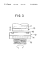
- FIG. 3 The structure of a microwelding tester is shown in FIG. 3 .
- An upward and downward moving aluminum alloy (AC8A) piston member 10 ( ⁇ 86mm ⁇ thickness 10mm) is provided with a heater 11 .
- a test piece support member 12 supported by a spring 13 is disposed at a position below the piston member 10 , and has an annular groove on the upper surface and has a heater 14 .
- a test piece 15 which is a piston ring is mounted in the annular groove of the test piece support member 12 and is supported in a state slightly protruding from the upper surface of the test piece support member 12 .
- the test piece support member 12 repeatedly rotates and reverses in a horizontal plane in 180°. Therefore, the test piece 15 which is the piston ring is tapped by the flat bottom of the upward and downward moving piston member 10 while repeatedly rotated and reversed in a horizontal plane in 180° by the test piece support member 12 .
- Rotation speed of piston member 15 c.p.m., 180°
- Test temperature 200° C.
- FIGS. 5A and 5B The structure of the pin-on-cylinder friction testing machine used in the scuffing test is shown in FIGS. 5A and 5B.
- a test piece 20 as the piston ring is mounted on the upper end of the outer circumferential surface 22 of a rotor 21 rotated around the horizontal axis.
- a load P is applied to the test piece 20 which is the piston ring, pressing the piston ring against the outer circumferential surface of the rotor 21 .
- the rotor 21 is rotated in this state, while supplying lubricating oil to the contact portion between the rotor 21 and the test piece 20 as the piston ring.
- the test piece was observed for the presence or absence of scuffing on the sliding surface after the testing machine was operated for specified times at a fixed load.
- the piston ring on which was formed the film of the embodiment had superior scuffing resistance as shown in Table 2.
- the scuffing resistance was low in the comparative example 1 having only the gas nitrided layer, the comparative examples 2 and 3 having an under film with a metal content outside the range of the present invention, and the comparative examples 4, 5 and 6 having an under film thickness ratio outside the range of the present invention for the sum of the diamond-like carbon film thickness and the under film thickness.
- test results in the above test are shown for the under film containing silicon, chromium and titanium respectively, however in the under film containing any of tungsten, molybdenum, niobium and vanadium, or in the under film containing two or more elements selected from the group consisting of silicon, titanium, tungsten, chromium, molybdenum, niobium, and vanadium, the same results as before can be obtained.
Abstract
A piston ring has a diamond-like carbon film formed in a thickness of 0.5 to 30 micrometers over an under film on the upper and lower surfaces. The under film is directly formed on the surfaces, or formed on a hard surface treatment layer consisting of a gas nitrided layer or a chromium plating film. The diamond-like carbon is configured with any one of an amorphous carbon structure, an amorphous carbon structure having partly a diamond structure, or an amorphous carbon structure having partly a graphite structure. The under film is comprised of one or more elements selected from the group consisting of silicon, titanium, tungsten, chromium, molybdenum, niobium and vanadium in an atomic content of 70 percent or more and below 100 percent, and the remaining content consisting of carbon, or one or more of said elements in an atomic content of 100 percent. The films may also be formed in the same way on the outer circumferential surface of the piston ring.
Description
1. Technical Field of Invention
The present invention relates to a piston ring for use in internal combustion engines.
2. Description of Related Art
In recent years, engines must meet increased demands for higher output, high revolutions per minute and longer product service life and must also comply with ever stricter exhaust gas emission regulations. The piston ring must therefore function in a yet harsher operating environment. Many of such piston rings are formed typically with a hard surface treatment layer such as chromium plating film, nitrided layer or physical vapor deposition film on the upper and lower surfaces and the outer circumferential surface.
However, piston rings having a nitrided layer or physical vapor deposition film are prone to wear the ring grooves of the aluminum alloy pistons. In particular, piston rings having nitrided layers are prone to cause aluminum adhesion on the upper and lower surfaces, increasing the wear on the ring grooves.
In the initial stage of engine operation, break-in between the cylinder and piston ring is not sufficient so that scuffing may occur between the cylinder and piston ring formed with the above mentioned hard surface treatment layer. Accordingly, a method to improve initial break-in characteristics of these hard surface treatment layers or a hard surface treatment layer having both scuffing resistance and wear resistance is needed.
To respond the above problem, the following arts have been proposed.
1. Japanese Patent Laid-open No. 8-184375
A film of either 98.0 to 99.5 percent molybdenum or chromium or both and the remainder of nitrogen was formed by physical vapor deposition on a nitrided layer or physical vapor deposition film in order to improve the initial break-in characteristics.
2. Japanese Patent Publication No. 5-54594
A TiN film was formed over a hard film comprised of CBN, TiC, Ti (C,N), SiC, diamonds or Al2O3 in order to improve the scuffing resistance.
On the other hand, the following art involved coating of artificial diamond material has been proposed.
3. Japanese Patent Laid-open No. 3-260362
A thin film of artificial diamond material was formed on the piston ring and on the top surface, external circumferential surface and ring groove of the piston in order to improve durability.
Further, the following art involved use of a diamond-like carbon film has been proposed.
4. Japanese Patent Laid-open No. 5-179451
In order to restrict the adhesion of ferrite structures, a film having amorphous carbon as the main constituent in which tungsten and/or silicon was dispersed was formed on the sliding surface which mates with a sliding surface formed of iron-type material containing ferrite. This technology is utilized for instance, in the hydraulic valve in power steering mechanisms.
However, under harsh engine operating conditions, the technology proposed in the above first method has the drawback that the molybdenum or chromium film wears away quickly. The technology proposed in the above second method has a TiN film with excessive hardness so that resistance to scuffing is inadequate. The technology proposed in the above third method has no detailed description of any kind regarding the thin film of artificial diamond material. The technology proposed in the above fourth method provides no description of aluminum adhesion on the upper and lower surfaces of the piston rings mating with aluminum alloy pistons. Besides the above mentioned technologies, a method is known, for suppressing aluminum adhesion in the initial stages of engine operation by coating the upper and lower surfaces of the piston ring with a synthetic resin film containing solid lubricant. However, this synthetic resin film has poor wear resistance, so this method has the drawback that suppression of the aluminum adhesion does not last long.
It is an object of the present invention to provide a piston ring with superior sliding characteristics such as resistance to aluminum adhesion, resistance to scuffing and initial break-in characteristics.
The present invention is a piston ring covered on a sliding surface of the piston ring with a diamond-like carbon film, wherein an under film is formed beneath the diamond-like carbon film and is comprised of one or more elements selected from the group consisting of silicon, titanium, tungsten, chromium, molybdenum, niobium and vanadium in an atomic content of 70 percent or more and below 100 percent, and the remaining content consisting of carbon, or one or more of said elements in an atomic content of 100 percent.
The diamond-like carbon forming a film of the present invention is configured from any one of the following structures.
1. Amorphous carbon structure
2. Amorphous carbon structure having partly a diamond structure.
3. Amorphous carbon structure having partly a graphite structure.
The sliding surface is the upper, lower or outer circumferential surfaces of the piston ring. The film of the present invention covers at least one surface of the upper, lower and outer circumferential surfaces of the piston ring.
The sliding surface of the piston ring of the present invention comprises a laminated structure of piston ring base material, under film, and diamond-like carbon film; or a laminated structure of piston ring base material, hard surface treatment layer, under film, and diamond-like carbon film. The hard surface treatment layer may be a chromium plating film, a nitrided layer or an ion plating film.
The resistance to aluminum adhesion, wear resistance and scuffing resistance of the diamond-like carbon film are inherently high, however a film having improved scuffing resistance, improved wear resistance and improved resistance to aluminum adhesion can be obtained by including one or more elements in an atomic content of 5 to 40 percent selected from the group consisting of silicon, titanium, tungsten, chromium, molybdenum, niobium, and vanadium. The one or more elements are present as metal or carbides or both.
The under film is firmly bonded to the piston ring base material or the hard surface treatment layer of any one of chromium plating film, nitrided layer and ion plating film, and also bonded to the diamond-like carbon film. The under film simultaneously alleviates strain occurring internally in the diamond-like carbon film.
Accordingly, the diamond-like carbon film of the present invention has high adhesive strength and is not prone to generate defects such as cracks, film collapse or pits during use.
The thickness of the under film is preferably within a range of 1 to 35 percent of the sum of the diamond-like carbon film thickness and the under film thickness. When the thickness is below 1 percent, the effect of alleviating strain occurring internally in the diamond-like carbon film can not be achieved. When the thickness exceeds 35 percent, the protective effect of the hard surface treatment layer that protects the diamond-like carbon film from the rear against deformation or loads from the sliding surface side can not be obtained. Further, the scuffing resistance of the under film exposed after wear of the diamond-like carbon film is poor so that the scuffing resistance becomes low.
The under film of the present invention has a film thickness taking resistance to scuffing into account, and quickly wears away not to deteriorate resistance to scuffing after the diamond-like carbon film has fulfilled its job in the initial break-in period and worn away.
The hard surface treatment layer consisting of any one of a chromium plating film, a nitrided layer or an ion plating film has a high level of hardness and can protect the diamond-like carbon film from the rear against deformation or loads from the sliding surface side and can keep the piston ring resistant to wear after the diamond-like carbon film and under film have worn away.
The piston ring of the present invention as explained above, has a diamond-like carbon film with superior adhesive strength and has superior resistance to aluminum adhesion, resistance to scuffing and initial break-in characteristics, and is particularly effective on cylinder bores and piston ring grooves of aluminum alloys.
FIGS. 1A, 1B and 1C are respectively longitudinal cross sectional views of a portion of the piston rings illustrating embodiments of the present invention.
FIGS. 2A and 2B are respectively longitudinal cross sectional views of a portion of the piston rings illustrating embodiments of the present invention.
FIG. 3 is a drawing showing a configuration of the microwelding tester.
FIG. 4 is a graph showing test results from the microwelding tests.
FIGS. 5A and 5B are drawings showing the structure of the pin-on-cylinder friction testing machine. FIG. 5A is a front view partly in cross section. FIG. 5B is a side view.
Hereafter, the embodiments of the present invention are explained while referring to FIGS. 1A through 1C and FIGS. 2A through 2B.
In FIG. 1A, a piston ring 1 is formed over the entire surface with a gas nitrided layer 2 in a thickness of 5 to 150 micrometers. A diamond-like carbon film 4 containing one or more elements in an atomic content of 5 to 40 percent selected from the group consisting of silicon, titanium, tungsten, chromium, molybdenum, niobium and vanadium is formed in a thickness of 0.5 to 30 micrometers over the under film 3 formed on the gas nitrided layer 2 at the upper and lower surfaces. The diamond-like carbon film 4 has a Vicker's hardness in a range of HV700 to HV2000. The under film 3 is comprised of one or more elements selected from the group consisting of silicon, titanium, tungsten, chromium, molybdenum, niobium and vanadium in an atomic content of 70 percent or more and below 100 percent, and the remaining content consisting of carbon, or one or more of said elements in an atomic content of 100 percent. The thickness of the under film 3 is within a range of 1 to 35 percent of the sum of the diamond-like carbon film 4 thickness and the under film 3 thickness.
Another example is shown in FIG. 1B in which a chromium plating film 5 is formed on the outer circumferential surface and upper and lower surfaces in a thickness of 1 to 150 micrometers instead of the gas nitrided layer 2 formed over the entire surface in FIG. 1A.
Yet another example is shown in FIG. 1C in which an ion plating film 6 such as of chromium nitride (CrN, Cr2N) or titanium nitride (TiN) is formed on the outer circumferential surface instead of the gas nitrided layer 2 formed over the entire surface in FIG. 1A.
In FIGS. 1A through 1C, the under film 3 and the diamond-like carbon film 4 were formed on the upper and lower surfaces of the piston ring 1, however the under film 3 and the diamond-like carbon film 4 may be formed on just one surface of either the upper or lower surface.
In FIG. 2A, a piston ring 1 is formed over the entire surface with a gas nitrided layer 2 in a thickness of 5 to 150 micrometers. A diamond-like carbon film 4 containing one or more elements in an atomic content of 5 to 40 percent selected from the group consisting of silicon, titanium, tungsten, chromium, molybdenum, niobium and vanadium is formed in a thickness of 0.5 to 30 micrometers over the under film 3 formed on the gas nitrided layer 2 at the outer circumferential surface. The diamond-like carbon film 4 has a Vicker's hardness in a range of HV700 to HV2000. The under film 3 is comprised of one or more elements selected from the group consisting of silicon, titanium, tungsten, chromium, molybdenum, niobium and vanadium in an atomic content of 70 percent or more and below 100 percent, and the remaining content consisting of carbon, or one or more of said elements in an atomic content of 100 percent. The thickness of the under film 3 is within a range of 1 to 35 percent of the sum of the diamond-like carbon film 4 thickness and the under film 3 thickness.
Another example is shown in FIG. 2B in which a chromium plating film 5 is formed on the outer circumferential surface in a thickness of 5 to 150 micrometers instead of the gas nitrided layer 2 formed over the entire surface in FIG. 2A.
The manufacturing method for the under film 3 and the diamond-like carbon film 4 is explained next. The under film 3 and the diamond-like carbon film 4 can be applied by a physical vapor deposition process such as reactive ion plating process or reactive sputtering process. An example is related below.
A piston ring is placed in a reactive sputtering device, and after raising a vacuum, an inert gas such as argon gas is introduced into the device while the piston ring is rotated, and the surface of the piston ring is cleaned by ion bombardment. A metal target of one or more elements selected from the group consisting of silicon, titanium, tungsten, chromium, molybdenum, niobium and vanadium is then sputtered with ions such as argon in a carbonic type gas environment, for example a hydrocarbon such as methane gas environment, and the vaporized metal is formed as an under film on the piston ring. The ratio of the respective contents of the one or more elements selected from the group consisting of silicon, titanium, tungsten, chromium, molybdenum, niobium and vanadium can be adjusted by changing the flow rate of the hydrocarbon gas. The carbonic type gas is not required when the under film is comprised of the one or more metallic elements in an atomic content of 100 percent.
After forming the under film as described above, the hydrocarbon gas flow rate, and the vaporizing speed of the metal from the metal target of one or more elements selected from the group consisting of silicon, titanium, tungsten, chromiumn, molybdenum, niobium and vanadium are adjusted. The diamond-like carbon film is then formed on the under film.
The ratio of the respective contents of the one or more elements selected from the group consisting of silicon, titanium, tungsten, chromium, molybdenum, niobium, and vanadium can be controlled by adjusting the pressure of the reactive gas as well as the evaporation speed of these elements.
Hereafter, the results of a microwelding test to evaluate adhesive strength of the diamond-like carbon film and the scuffing test in the piston ring of the present invention are explained.
Table 1 shows films applied by the previously related method onto a 13Cr stainless steel piston ring. The films are formed in the sequence of hard surface treatment layer, under film and diamond-like carbon film from the piston ring base material.
The hardness and other items of the hard surface treatment layer for Table 1 are shown next.
The gas nitrided layer has a Vicker's hardness of HV1100, and the thickness of 50 micrometers. The chromium plating film has a Vicker's hardness of HV950, and plating thickness of 70 micrometers. The ion plating film is a CrN film with a Vicker's hardness of HV1800, and film thickness of 30 micrometers.
The respective metal contents contained in the diamond-like carbon film in Table 1 are as follows.
Embodiments 2 and 5 and comparative examples 2 and 5
chromium 30 atomic percent
Note 1: The DLC film of Table 1 is the diamond-like carbon film.
Note 2: The under film thickness % of Table 1 is the under film thickness ratio for the sum of the diamond-like carbon film thickness and the under film thickness.
| TABLE 1 | ||||||
| HARD SURFACE | METAL CONTENT | UNDER FILM | DLC FILM | UNDER FILM | ||
| TREATMENT | UNDER | IN UNDER | THICKNESS | THICKNESS | THICKNESS | |
| NO. | LAYER | FILM | FILM ATOMIC % | μm | | % |
| EMBODIMENT |
| 1 | Gas nitrided | |
100 | 0.05 | 4.95 | 1 |
| |
||||||
| 2 | Gas nitrided | Cr | 90 | 0.25 | 4.75 | 5 |
| |
||||||
| 3 | Chromium | Si | 70 | 0.5 | 4.5 | 10 |
| |
||||||
| 4 | Gas nitrided | |
100 | 1.25 | 3.75 | 25 |
| |
||||||
| 5 | Gas nitrided | |
100 | 1.75 | 3.25 | 35 |
| |
||||||
| 6 | Ion plating | Si | 80 | 1.0 | 4.0 | 20 |
| film | ||||||
| COMPARATIVE | ||||||
| EXAMPLE | ||||||
| 1 | Gas nitrided | — | — | — | — | — |
| |
||||||
| 2 | Gas nitrided | Cr | 65 | 0.5 | 4.5 | 10 |
| |
||||||
| 3 | Gas nitrided | Ti | 50 | 0.5 | 4.5 | 10 |
| |
||||||
| 4 | Gas nitrided | |
100 | 0.025 | 4.975 | 0.5 |
| |
||||||
| 5 | Gas nitrided | |
100 | 2.0 | 3.0 | 40 |
| |
||||||
| 6 | Gas nitrided | |
100 | 2.5 | 2.5 | 50 |
| layer | ||||||
1. Microwelding test
Microwelding tests were performed utilizing the piston rings formed on the upper and lower surfaces with the under film and diamond-like carbon film, on the entire surface with the gas nitrided layer, and on the upper and lower surfaces with the chromium plating film or ion plating film in Table 1.
(1) Microwelding tester
The structure of a microwelding tester is shown in FIG. 3. An upward and downward moving aluminum alloy (AC8A) piston member 10 (ø86mm×thickness 10mm) is provided with a heater 11. A test piece support member 12 supported by a spring 13 is disposed at a position below the piston member 10, and has an annular groove on the upper surface and has a heater 14. A test piece 15 which is a piston ring is mounted in the annular groove of the test piece support member 12 and is supported in a state slightly protruding from the upper surface of the test piece support member 12. The test piece support member 12 repeatedly rotates and reverses in a horizontal plane in 180°. Therefore, the test piece 15 which is the piston ring is tapped by the flat bottom of the upward and downward moving piston member 10 while repeatedly rotated and reversed in a horizontal plane in 180° by the test piece support member 12.
(2) Test conditions
Tap load: 1000 N
Tap speed: 900 r.p.m.
Rotation speed of piston member: 15 c.p.m., 180°
Test temperature: 200° C.
Lubricant: Dropping of 10W engine oil
(3) Test results
As shown in Table 4, all of the piston rings formed with the films of the embodiments had superior resistance to aluminum adhesion.
2. Scuffing test
Scuffing tests were performed utilizing the piston rings formed on the outer circumferential surface with the under film and diamond-like carbon film, on the entire surface with the gas nitrided layer, and on the outer circumferential surface with the chromium plating film or ion plating film in Table 1.
(1) Pin-on-cylinder friction testing machine
The structure of the pin-on-cylinder friction testing machine used in the scuffing test is shown in FIGS. 5A and 5B. A test piece 20 as the piston ring is mounted on the upper end of the outer circumferential surface 22 of a rotor 21 rotated around the horizontal axis. A load P is applied to the test piece 20 which is the piston ring, pressing the piston ring against the outer circumferential surface of the rotor 21. The rotor 21 is rotated in this state, while supplying lubricating oil to the contact portion between the rotor 21 and the test piece 20 as the piston ring. The test piece was observed for the presence or absence of scuffing on the sliding surface after the testing machine was operated for specified times at a fixed load.
(2) Test conditions
Rotation speed: 1000 r.p.m.
Load 150 N
Time 60 seconds
Lubricating oil Dropping of 10 W engine oil
Temperature Room temperature
(3) Rotor 21
Material: Flake graphite cast iron
(4) Test results
The piston ring on which was formed the film of the embodiment had superior scuffing resistance as shown in Table 2. In contrast, the scuffing resistance was low in the comparative example 1 having only the gas nitrided layer, the comparative examples 2 and 3 having an under film with a metal content outside the range of the present invention, and the comparative examples 4, 5 and 6 having an under film thickness ratio outside the range of the present invention for the sum of the diamond-like carbon film thickness and the under film thickness.
| TABLE 2 | ||
| NO. | | |
| EMBODIMENT | ||
| 1 | No |
|
| 2 | No |
|
| 3 | No |
|
| 4 | No |
|
| 5 | No |
|
| 6 | No scuffing | |
| |
1 | Scuffing |
| EXAMPLE | 2 | |
| 3 | |
|
| 4 | |
|
| 5 | |
|
| 6 | Scuffing | |
The test results in the above test are shown for the under film containing silicon, chromium and titanium respectively, however in the under film containing any of tungsten, molybdenum, niobium and vanadium, or in the under film containing two or more elements selected from the group consisting of silicon, titanium, tungsten, chromium, molybdenum, niobium, and vanadium, the same results as before can be obtained.
Although the present invention has been described with reference to the preferred embodiments, it is apparent that the present invention is not limited to the aforesaid preferred embodiments, but various modification can be attained without departing from its scope.
Claims (16)
1. A piston ring having a diamond-like carbon film on a sliding surface of said piston ring, wherein an under film is formed beneath said diamond-like carbon film, and consists of one or more elements selected from the group consisting of silicon, titanium, tungsten, chromium, molybdenum, niobium and vanadium in an atomic content of 70 percent or more and below 100 percent, and the remaining content consisting of carbon; or one or more elements selected from the group consisting of silicon, titanium, tungsten, chromium, molybdenum, niobium and vanadium in an atomic content of 100 percent, and the thickness of said under film is within a range of 1 to 35 percent of the sum of said diamond-like carbon film thickness and said under film thickness, and said diamond-like carbon film is worn and said under film is exposed during use of said piston ring.
2. A piston ring as claimed in claim 1, wherein said under film is formed over a hard surface treatment layer of any one of a chromium plating film, a nitrided layer and an ion plating film.
3. A piston ring as claimed in claim 1, wherein said under film is directly formed on the sliding surface of said piston ring.
4. A piston ring as claimed in claim 1, wherein said sliding surface is at least one surface of the upper and lower surfaces of said piston ring.
5. A piston ring as claimed in claim 1, wherein said sliding surface is the outer circumferential surface of said piston ring.
6. A piston ring as claimed in claim 1, wherein the thickness of said under film is less than 2 μm.
7. A piston ring as claimed in claim 6, wherein said diamond-like carbon film contains one or more elements selected from the group consisting of silicon, titanium, tungsten, chromium, molybdenum, niobium and vanadium in an atomic content of 5 to 40 percent.
8. A piston ring as claimed in claim 6, wherein said under film is formed over a hard surface treatment layer of any one of a chromium plating film, a nitrided layer and an ion plating film.
9. A piston ring as claimed in claim 6, wherein said under film is directly formed on the sliding surface of said piston ring.
10. A piston ring as claimed in claim 6, wherein said sliding surface is at least one surface of the upper and lower surfaces of said piston ring.
11. A piston ring as claimed in claim 6, wherein said sliding surface is the outer circumferential surface of said piston ring.
12. A piston ring as claimed in claim 1, wherein said diamond-like carbon film contains one or more elements selected from the group consisting of silicon, titanium, tungsten, chromium, molybdenum, niobium and vanadium in an atomic content of 5 to 40 percent.
13. A piston ring as claimed in claim 12, wherein said under film is formed over a hard surface treatment layer of any one of a chromium plating film, a nitrided layer and an ion plating film.
14. A piston ring as claimed in claim 12, wherein said under film is directly formed on the sliding surface of said piston ring.
15. A piston ring as claimed in claim 12, wherein said sliding surface is at least one surface of the upper and lower surfaces of said piston ring.
16. A piston ring as claimed in claim 12, wherein said sliding surface is the outer circumferential surface of said piston ring.
Applications Claiming Priority (2)
| Application Number | Priority Date | Filing Date | Title |
|---|---|---|---|
| JP10-309442 | 1998-10-15 | ||
| JP10309442A JP2000120870A (en) | 1998-10-15 | 1998-10-15 | Piston ring |
Publications (1)
| Publication Number | Publication Date |
|---|---|
| US6325385B1 true US6325385B1 (en) | 2001-12-04 |
Family
ID=17993056
Family Applications (1)
| Application Number | Title | Priority Date | Filing Date |
|---|---|---|---|
| US09/352,345 Expired - Lifetime US6325385B1 (en) | 1998-10-15 | 1999-07-13 | Piston ring |
Country Status (3)
| Country | Link |
|---|---|
| US (1) | US6325385B1 (en) |
| JP (1) | JP2000120870A (en) |
| GB (1) | GB2344150B (en) |
Cited By (65)
| Publication number | Priority date | Publication date | Assignee | Title |
|---|---|---|---|---|
| US6508473B1 (en) * | 1999-04-07 | 2003-01-21 | Teikoku Piston Ring Co., Ltd. | Piston ring |
| US6698763B2 (en) * | 2001-02-27 | 2004-03-02 | Nippon Piston Ring Co., Ltd. | Piston ring |
| US20040222594A1 (en) * | 2003-05-08 | 2004-11-11 | Dresser-Rand Company | Oil film sealing device for a rotating shaft |
| EP1479946A2 (en) * | 2003-05-23 | 2004-11-24 | Nissan Motor Company, Limited | Piston for internal combustion engine |
| US20040234770A1 (en) * | 2001-09-27 | 2004-11-25 | Hiroyuki Mori | High friction sliding member |
| US20050067790A1 (en) * | 2003-09-26 | 2005-03-31 | Smith Thomas J. | Piston ring having chromium coating |
| US20050119136A1 (en) * | 2003-03-26 | 2005-06-02 | Rebecca Castle | Method for lubricating diamond-like carbon coated surfaces |
| US20050203054A1 (en) * | 2000-01-10 | 2005-09-15 | Saul Yedgar | Use of lipid conjugates in the treatment of diseases |
| US20050269787A1 (en) * | 2002-07-25 | 2005-12-08 | Kabushiki Kaisha Riken | Piston ring |
| US20060105171A1 (en) * | 2004-11-12 | 2006-05-18 | Labarge William J | Coated article |
| US20060189571A1 (en) * | 2000-01-10 | 2006-08-24 | Saul Yedgar | Use of lipid conjugates in the treatment of infection |
| US20060280946A1 (en) * | 2005-05-20 | 2006-12-14 | United Technologies Corporation | Metal-containing diamond-like-carbon coating compositions |
| US20060293276A1 (en) * | 2000-01-10 | 2006-12-28 | Saul Yedgar | Use of lipid conjugates in the treatment of disease |
| US20070078107A1 (en) * | 2000-01-10 | 2007-04-05 | Saul Yedgar | Use of lipid conjugates in the treatment of disease |
| US20070117779A1 (en) * | 2000-01-10 | 2007-05-24 | Saul Yedgar | Use of lipid conjugates in the treatment of disease |
| DE102005063123B3 (en) * | 2005-12-30 | 2007-05-31 | Federal-Mogul Burscheid Gmbh | Piston ring for sealing chamber in cylinder has running-in layer containing hydrogen and nanocrystalline carbide phases |
| US20070128807A1 (en) * | 2003-12-19 | 2007-06-07 | Manfred Fischer | Piston ring and method for the production thereof |
| US20070185052A1 (en) * | 2005-08-03 | 2007-08-09 | Saul Yedgar | Use of lipid conjugates in cystic fibrosis and applications thereof |
| US20070210524A1 (en) * | 2004-03-26 | 2007-09-13 | Christian Herbst-Dederichs | Piston rings |
| US7273655B2 (en) | 1999-04-09 | 2007-09-25 | Shojiro Miyake | Slidably movable member and method of producing same |
| US20070267820A1 (en) * | 2006-05-16 | 2007-11-22 | Skf Usa Inc. | Mechanical end face seal with ultrahard face material |
| US20080113935A1 (en) * | 2004-03-02 | 2008-05-15 | Saul Yedgar | Use of lipid conjugates in the treatment of diseases or disorders of the eye |
| US20080203674A1 (en) * | 2005-05-26 | 2008-08-28 | Nv Bekaert Sa | Piston Ring Having Hard Multi-Layer Coating |
| US20080220257A1 (en) * | 2005-08-18 | 2008-09-11 | Nv Bekaert Sa | Substrate Coated with a Layered Structure Comprising a Tetrahedral Carbon Layer and a Softer Outer Layer |
| US20080293672A1 (en) * | 2000-01-10 | 2008-11-27 | Saul Yedgar | Lipid conjugates in the treatment of disease |
| US20090026712A1 (en) * | 2006-02-28 | 2009-01-29 | Minoru Kawanishi | Sliding Member |
| US20090174150A1 (en) * | 2008-01-08 | 2009-07-09 | Thomas Smith | Lateral side protection of a piston ring with a thermally sprayed coating |
| US7608598B2 (en) | 2000-01-10 | 2009-10-27 | Yissum Research Development Company Of The Hebrew University Of Jerusalem | Use of lipid conjugates in the treatment of conjunctivitis |
| US20090325876A1 (en) * | 2004-09-29 | 2009-12-31 | Saul Yedgar | Use of lipid conjugates in the treatment of diseases associated with vasculature |
| US7650976B2 (en) | 2003-08-22 | 2010-01-26 | Nissan Motor Co., Ltd. | Low-friction sliding member in transmission, and transmission oil therefor |
| US20100022473A1 (en) * | 2001-01-10 | 2010-01-28 | Saul Yedgar | Use of lipid conjugates in the treatment of diseases associated with vasculature |
| US20100117304A1 (en) * | 2007-02-17 | 2010-05-13 | Johannes Esser | Piston ring |
| US7772196B2 (en) | 2000-01-10 | 2010-08-10 | Yissum Research Development Company Of The Hebrew University Of Jerusalem | Use of lipid conjugates in the treatment of diseases |
| US7771821B2 (en) | 2003-08-21 | 2010-08-10 | Nissan Motor Co., Ltd. | Low-friction sliding member and low-friction sliding mechanism using same |
| US7811999B2 (en) | 2000-01-10 | 2010-10-12 | Yissum Research Development Company Of The Hebrew University Of Jerusalem, Ltd. | Use of lipid conjugates in the treatment of diseases |
| US7893226B2 (en) | 2004-09-29 | 2011-02-22 | Yissum Research Development Company Of The Hebrew University Of Jerusalem, Ltd. | Use of lipid conjugates in the treatment of diseases |
| DE102010029256A1 (en) | 2010-05-25 | 2011-12-01 | Federal-Mogul Burscheid Gmbh | Slide |
| US8096205B2 (en) | 2003-07-31 | 2012-01-17 | Nissan Motor Co., Ltd. | Gear |
| DE102010033543A1 (en) * | 2010-08-05 | 2012-02-09 | Bayerische Motoren Werke Aktiengesellschaft | Coating of components made of steel comprises depositing amorphous carbon layer on hydrocarbon containing tungsten layer that is applied directly on the component surface |
| US8152377B2 (en) | 2002-11-06 | 2012-04-10 | Nissan Motor Co., Ltd. | Low-friction sliding mechanism |
| US8206035B2 (en) | 2003-08-06 | 2012-06-26 | Nissan Motor Co., Ltd. | Low-friction sliding mechanism, low-friction agent composition and method of friction reduction |
| US20120177915A1 (en) * | 2009-09-15 | 2012-07-12 | Nippon Itf Inc. | Lubricant composition and sliding mechanism using the lubricant composition |
| US20120205875A1 (en) * | 2009-08-13 | 2012-08-16 | Marcus Kennedy | Sliding element, in particular a piston ring, having a coating |
| US20120227699A1 (en) * | 2011-03-08 | 2012-09-13 | GM Global Technology Operations LLC | Linerless engine |
| WO2012122693A1 (en) * | 2011-03-14 | 2012-09-20 | 仪征双环活塞环有限公司 | Piston ring with diamond-like gradient coating |
| CN103016200A (en) * | 2011-09-27 | 2013-04-03 | 现代自动车株式会社 | Piston ring for engine and manufacturing method thereof |
| US8575076B2 (en) | 2003-08-08 | 2013-11-05 | Nissan Motor Co., Ltd. | Sliding member and production process thereof |
| WO2014131098A1 (en) * | 2013-02-27 | 2014-09-04 | Mahle Metal Leve S/A | Piston ring |
| US8859524B2 (en) | 2005-11-17 | 2014-10-14 | Yissum Research Development Company Of The Hebrew University Of Jerusalem | Lipid conjugates in the treatment of chronic rhinosinusitis |
| US20140323368A1 (en) * | 2011-12-07 | 2014-10-30 | Mahle - Metal Leve S/A | Sliding component for use in an internal combustion engine |
| US8906882B2 (en) | 2005-11-17 | 2014-12-09 | Yissum Research Development Company Of The Hebrew University Of Jerusalem | Lipid conjugates in the treatment of allergic rhinitis |
| US9040078B2 (en) | 2000-01-10 | 2015-05-26 | Yissum Research Development Company Of The Hebrew University Of Jerusalem | Use of lipid conjugates in the treatment of diseases of the nervous system |
| US9057442B2 (en) | 2012-06-19 | 2015-06-16 | C.T.I. Traffic Industries Co., Ltd. | Structure of piston ring |
| US20160003356A1 (en) * | 2013-02-28 | 2016-01-07 | Nippon Piston Ring Co., Ltd. | Hard carbon coating film |
| US9447879B2 (en) * | 2012-12-07 | 2016-09-20 | Kabushiki Kaisha Riken | Piston ring |
| US20170089241A1 (en) * | 2011-06-15 | 2017-03-30 | Henkel Ag & Co. Kgaa | Method and apparatus for reducing emissions and/or reducing friction in an internal combustion engine |
| WO2017149082A1 (en) * | 2016-03-04 | 2017-09-08 | Mahle International Gmbh | Piston ring |
| CN107614944A (en) * | 2015-07-31 | 2018-01-19 | 日本活塞环株式会社 | Piston ring and its manufacture method |
| US10246767B2 (en) * | 2014-04-02 | 2019-04-02 | Mahle Metal Leve S/A | Sliding element, internal combustion engine and process for obtaining sliding element |
| US10302197B2 (en) * | 2016-08-29 | 2019-05-28 | Japon Traffic Tech Corp. | Graphite cast iron nitrided piston ring |
| DE102019200682A1 (en) * | 2019-01-21 | 2020-07-23 | Technische Universität Dresden | Cutting tool with spatially structured coating |
| US11013811B2 (en) | 2009-05-11 | 2021-05-25 | Yissum Research Development Company Of The Hebrew University Of Jerusalem Ltd. | Lipid-polymer conjugates, their preparation and uses thereof |
| US11143302B2 (en) * | 2016-06-30 | 2021-10-12 | Mahle Metal Leve S/A | Sliding element for internal combustion engines |
| US20220033975A1 (en) * | 2018-11-08 | 2022-02-03 | Nanofilm Technologies International Limited | Ta-c based coatings with improved hardness |
| US11408508B2 (en) | 2017-11-30 | 2022-08-09 | Federal-Mogul Burscheid Gmbh | Piston ring |
Families Citing this family (11)
| Publication number | Priority date | Publication date | Assignee | Title |
|---|---|---|---|---|
| JP4915891B2 (en) * | 2003-08-21 | 2012-04-11 | 日産自動車株式会社 | Low friction sliding member |
| JP4944444B2 (en) * | 2004-01-20 | 2012-05-30 | 株式会社日立製作所 | Fuel container for fuel cell |
| DE102004041235A1 (en) * | 2004-08-26 | 2006-03-02 | Ina-Schaeffler Kg | Wear resistant coating and method of making same |
| US7806598B2 (en) * | 2005-03-18 | 2010-10-05 | The Timken Company | Method of protecting roller element bearing assemblies against oil-out conditions and bearing assemblies made thereby |
| JP4775757B2 (en) * | 2005-04-13 | 2011-09-21 | 三菱マテリアル株式会社 | Surface-coated cermet cutting tool with excellent wear resistance due to lubricated amorphous carbon coating |
| JP4898162B2 (en) * | 2005-07-25 | 2012-03-14 | 東芝キヤリア株式会社 | Hermetic compressor and refrigeration cycle apparatus |
| JP2008241032A (en) * | 2007-02-28 | 2008-10-09 | Nippon Piston Ring Co Ltd | Piston ring and its manufacturing method |
| JP2012202522A (en) | 2011-03-28 | 2012-10-22 | Tpr Co Ltd | Piston ring |
| JP5977322B2 (en) * | 2014-11-25 | 2016-08-24 | Tpr株式会社 | piston ring |
| JP2016160777A (en) | 2015-02-27 | 2016-09-05 | ヤマハ発動機株式会社 | Internal combustion engine for saddle-riding type vehicle and saddle-riding type vehicle |
| WO2017026042A1 (en) * | 2015-08-10 | 2017-02-16 | 日本アイ・ティ・エフ株式会社 | Piston ring and engine |
Citations (25)
| Publication number | Priority date | Publication date | Assignee | Title |
|---|---|---|---|---|
| US3595590A (en) * | 1968-06-21 | 1971-07-27 | Goetzewerke | Piston ring |
| US3615099A (en) * | 1969-02-26 | 1971-10-26 | Ramsey Corp | Multiple layer faced piston rings |
| US3770286A (en) * | 1971-03-11 | 1973-11-06 | Dana Corp | Piston ring |
| US3909252A (en) * | 1973-11-01 | 1975-09-30 | Suzuki Motor Co | Wear-resistant cast iron for sliding surfaces |
| US3932228A (en) * | 1973-11-01 | 1976-01-13 | Suzuki Jidosha Kogyo Kabushiki Kaisha | Metal material for sliding surfaces |
| US4859493A (en) * | 1987-03-31 | 1989-08-22 | Lemelson Jerome H | Methods of forming synthetic diamond coatings on particles using microwaves |
| US4974498A (en) | 1987-03-31 | 1990-12-04 | Jerome Lemelson | Internal combustion engines and engine components |
| JPH03260362A (en) | 1990-03-05 | 1991-11-20 | Jerome H Lemelson | Internal-combustion engine and its factors |
| US5190823A (en) * | 1989-07-31 | 1993-03-02 | General Electric Company | Method for improving adhesion of synthetic diamond coatings to substrates |
| JPH0554594A (en) | 1992-02-05 | 1993-03-05 | Konica Corp | Production of video tape cassette |
| JPH05179451A (en) | 1991-12-27 | 1993-07-20 | Toyota Motor Corp | Combination of sliding member |
| US5237967A (en) | 1993-01-08 | 1993-08-24 | Ford Motor Company | Powertrain component with amorphous hydrogenated carbon film |
| US5370195A (en) * | 1993-09-20 | 1994-12-06 | Smith International, Inc. | Drill bit inserts enhanced with polycrystalline diamond |
| US5382293A (en) * | 1990-08-03 | 1995-01-17 | Fujitsu Limited | Plasma jet CVD apparatus for forming diamond films |
| US5531195A (en) * | 1993-08-25 | 1996-07-02 | Nippon Piston Ring Co., Ltd. | Piston ring |
| JPH08184375A (en) | 1994-12-29 | 1996-07-16 | Teikoku Piston Ring Co Ltd | Piston ring and manufacture thereof |
| US5582414A (en) * | 1993-06-07 | 1996-12-10 | Teikoku Piston Ring Co., Ltd. | Sliding member and method for manufacturing the same |
| US5601293A (en) * | 1994-12-22 | 1997-02-11 | Teikoku Piston Ring Co., Ltd. | Sliding member with hard ternery film |
| US5712000A (en) * | 1995-10-12 | 1998-01-27 | Hughes Aircraft Company | Large-scale, low pressure plasma-ion deposition of diamondlike carbon films |
| US5786038A (en) | 1995-06-07 | 1998-07-28 | Conley; James G. | Synthetic diamond layers having wear resistant coatings formed in situ and methods of applying such coatings |
| US5879816A (en) * | 1995-11-30 | 1999-03-09 | Nihon Parkerizing Co., Ltd. | Metallic sliding material |
| EP0905419A2 (en) | 1997-09-30 | 1999-03-31 | Teikoku Piston Ring Co., LTd. | Piston ring |
| EP0905420A2 (en) | 1997-09-30 | 1999-03-31 | Teikoku Piston Ring Co., LTd. | Piston ring |
| US6046758A (en) * | 1998-03-10 | 2000-04-04 | Diamonex, Incorporated | Highly wear-resistant thermal print heads with silicon-doped diamond-like carbon protective coatings |
| US6083570A (en) * | 1987-03-31 | 2000-07-04 | Lemelson; Jerome H. | Synthetic diamond coatings with intermediate amorphous metal bonding layers and methods of applying such coatings |
-
1998
- 1998-10-15 JP JP10309442A patent/JP2000120870A/en active Pending
-
1999
- 1999-07-13 US US09/352,345 patent/US6325385B1/en not_active Expired - Lifetime
- 1999-10-05 GB GB9923530A patent/GB2344150B/en not_active Expired - Lifetime
Patent Citations (25)
| Publication number | Priority date | Publication date | Assignee | Title |
|---|---|---|---|---|
| US3595590A (en) * | 1968-06-21 | 1971-07-27 | Goetzewerke | Piston ring |
| US3615099A (en) * | 1969-02-26 | 1971-10-26 | Ramsey Corp | Multiple layer faced piston rings |
| US3770286A (en) * | 1971-03-11 | 1973-11-06 | Dana Corp | Piston ring |
| US3932228A (en) * | 1973-11-01 | 1976-01-13 | Suzuki Jidosha Kogyo Kabushiki Kaisha | Metal material for sliding surfaces |
| US3909252A (en) * | 1973-11-01 | 1975-09-30 | Suzuki Motor Co | Wear-resistant cast iron for sliding surfaces |
| US4859493A (en) * | 1987-03-31 | 1989-08-22 | Lemelson Jerome H | Methods of forming synthetic diamond coatings on particles using microwaves |
| US4974498A (en) | 1987-03-31 | 1990-12-04 | Jerome Lemelson | Internal combustion engines and engine components |
| US6083570A (en) * | 1987-03-31 | 2000-07-04 | Lemelson; Jerome H. | Synthetic diamond coatings with intermediate amorphous metal bonding layers and methods of applying such coatings |
| US5190823A (en) * | 1989-07-31 | 1993-03-02 | General Electric Company | Method for improving adhesion of synthetic diamond coatings to substrates |
| JPH03260362A (en) | 1990-03-05 | 1991-11-20 | Jerome H Lemelson | Internal-combustion engine and its factors |
| US5382293A (en) * | 1990-08-03 | 1995-01-17 | Fujitsu Limited | Plasma jet CVD apparatus for forming diamond films |
| JPH05179451A (en) | 1991-12-27 | 1993-07-20 | Toyota Motor Corp | Combination of sliding member |
| JPH0554594A (en) | 1992-02-05 | 1993-03-05 | Konica Corp | Production of video tape cassette |
| US5237967A (en) | 1993-01-08 | 1993-08-24 | Ford Motor Company | Powertrain component with amorphous hydrogenated carbon film |
| US5582414A (en) * | 1993-06-07 | 1996-12-10 | Teikoku Piston Ring Co., Ltd. | Sliding member and method for manufacturing the same |
| US5531195A (en) * | 1993-08-25 | 1996-07-02 | Nippon Piston Ring Co., Ltd. | Piston ring |
| US5370195A (en) * | 1993-09-20 | 1994-12-06 | Smith International, Inc. | Drill bit inserts enhanced with polycrystalline diamond |
| US5601293A (en) * | 1994-12-22 | 1997-02-11 | Teikoku Piston Ring Co., Ltd. | Sliding member with hard ternery film |
| JPH08184375A (en) | 1994-12-29 | 1996-07-16 | Teikoku Piston Ring Co Ltd | Piston ring and manufacture thereof |
| US5786038A (en) | 1995-06-07 | 1998-07-28 | Conley; James G. | Synthetic diamond layers having wear resistant coatings formed in situ and methods of applying such coatings |
| US5712000A (en) * | 1995-10-12 | 1998-01-27 | Hughes Aircraft Company | Large-scale, low pressure plasma-ion deposition of diamondlike carbon films |
| US5879816A (en) * | 1995-11-30 | 1999-03-09 | Nihon Parkerizing Co., Ltd. | Metallic sliding material |
| EP0905419A2 (en) | 1997-09-30 | 1999-03-31 | Teikoku Piston Ring Co., LTd. | Piston ring |
| EP0905420A2 (en) | 1997-09-30 | 1999-03-31 | Teikoku Piston Ring Co., LTd. | Piston ring |
| US6046758A (en) * | 1998-03-10 | 2000-04-04 | Diamonex, Incorporated | Highly wear-resistant thermal print heads with silicon-doped diamond-like carbon protective coatings |
Cited By (105)
| Publication number | Priority date | Publication date | Assignee | Title |
|---|---|---|---|---|
| US6508473B1 (en) * | 1999-04-07 | 2003-01-21 | Teikoku Piston Ring Co., Ltd. | Piston ring |
| US7273655B2 (en) | 1999-04-09 | 2007-09-25 | Shojiro Miyake | Slidably movable member and method of producing same |
| US20060189569A1 (en) * | 2000-01-10 | 2006-08-24 | Saul Yedgar | Use of lipid conjugates in the treatment of infection |
| US20100317591A1 (en) * | 2000-01-10 | 2010-12-16 | Saul Yedgar | Use of lipid conjugates in the treatment of diseases |
| US7811999B2 (en) | 2000-01-10 | 2010-10-12 | Yissum Research Development Company Of The Hebrew University Of Jerusalem, Ltd. | Use of lipid conjugates in the treatment of diseases |
| US8076312B2 (en) * | 2000-01-10 | 2011-12-13 | Yissum Research Development Company Of The Hebrew University Of Jerusalem Ltd | Use of lipid conjugates in the treatment of disease |
| US7772196B2 (en) | 2000-01-10 | 2010-08-10 | Yissum Research Development Company Of The Hebrew University Of Jerusalem | Use of lipid conjugates in the treatment of diseases |
| US20100087397A1 (en) * | 2000-01-10 | 2010-04-08 | Saul Yedgar | Use of lipid conjugates in the treatment of conjunctivitis |
| US20050203054A1 (en) * | 2000-01-10 | 2005-09-15 | Saul Yedgar | Use of lipid conjugates in the treatment of diseases |
| US7608598B2 (en) | 2000-01-10 | 2009-10-27 | Yissum Research Development Company Of The Hebrew University Of Jerusalem | Use of lipid conjugates in the treatment of conjunctivitis |
| US9040078B2 (en) | 2000-01-10 | 2015-05-26 | Yissum Research Development Company Of The Hebrew University Of Jerusalem | Use of lipid conjugates in the treatment of diseases of the nervous system |
| US20060189571A1 (en) * | 2000-01-10 | 2006-08-24 | Saul Yedgar | Use of lipid conjugates in the treatment of infection |
| US20110230652A1 (en) * | 2000-01-10 | 2011-09-22 | Saul Yedgar | Use of lipid conjugates in the treatment of diseases |
| US20060189570A1 (en) * | 2000-01-10 | 2006-08-24 | Saul Yedgar | Use of lipid conjugates in the treatment of infection |
| US9012396B2 (en) | 2000-01-10 | 2015-04-21 | Yissum Research Development Company Of The Hebrew University Of Jerusalem | Use of lipid conjugates in the treatment of conjunctivitis |
| US20060293276A1 (en) * | 2000-01-10 | 2006-12-28 | Saul Yedgar | Use of lipid conjugates in the treatment of disease |
| US20070078107A1 (en) * | 2000-01-10 | 2007-04-05 | Saul Yedgar | Use of lipid conjugates in the treatment of disease |
| US20070117779A1 (en) * | 2000-01-10 | 2007-05-24 | Saul Yedgar | Use of lipid conjugates in the treatment of disease |
| US7504384B2 (en) | 2000-01-10 | 2009-03-17 | Yissum Research Development Company Of The Hebrew University Of Jerusalem | Use of lipid conjugates in the treatment of infection |
| US8304395B2 (en) | 2000-01-10 | 2012-11-06 | Yissum Research Development Company Of The Hebrew University Of Jerusalem Ltd. | Lipid conjugates in the treatment of disease |
| US8901103B2 (en) | 2000-01-10 | 2014-12-02 | Yissum Research Development Company Of The Hebrew University Of Jerusalem | Use of lipid conjugates in the treatment of diseases |
| US8372815B2 (en) | 2000-01-10 | 2013-02-12 | Yissum Research Development Company | Use of lipid conjugates in the treatment of conjunctivitis |
| US8865878B2 (en) | 2000-01-10 | 2014-10-21 | Yissum Research Development Company Of The Hebrew University Of Jerusalem | Use of lipid conjugates in the treatment of diseases |
| US20080293672A1 (en) * | 2000-01-10 | 2008-11-27 | Saul Yedgar | Lipid conjugates in the treatment of disease |
| US8383787B2 (en) | 2000-01-10 | 2013-02-26 | Yissum Research Development Company | Use of lipid conjugates in the treatment of diseases |
| US8501701B2 (en) | 2000-01-10 | 2013-08-06 | Yissum Research Development Company Of The Hebrew University Of Jerusalem Ltd. | Use of lipid conjugates in the treatment of disease |
| US8916539B2 (en) | 2000-01-10 | 2014-12-23 | Yissum Research Development Company Of The Hebrew University Of Jerusalem | Use of lipid conjugates in the treatment of disease |
| US7393938B2 (en) | 2000-01-10 | 2008-07-01 | Yissum Research Development Company Of The Hebrew University Of Jerusalem | Use of lipid conjugates in the treatment of diseases |
| US20100022473A1 (en) * | 2001-01-10 | 2010-01-28 | Saul Yedgar | Use of lipid conjugates in the treatment of diseases associated with vasculature |
| US8883761B2 (en) | 2001-01-10 | 2014-11-11 | Yissum Research Development Company Of The Hebrew University Of Jerusalem | Use of lipid conjugates in the treatment of diseases associated with vasculature |
| US6698763B2 (en) * | 2001-02-27 | 2004-03-02 | Nippon Piston Ring Co., Ltd. | Piston ring |
| US20040234770A1 (en) * | 2001-09-27 | 2004-11-25 | Hiroyuki Mori | High friction sliding member |
| US7537835B2 (en) * | 2001-09-27 | 2009-05-26 | Kabushiki Kaisha Toyota Chuo Kenkyusho | High friction sliding member |
| US20050269787A1 (en) * | 2002-07-25 | 2005-12-08 | Kabushiki Kaisha Riken | Piston ring |
| US8152377B2 (en) | 2002-11-06 | 2012-04-10 | Nissan Motor Co., Ltd. | Low-friction sliding mechanism |
| US20050119136A1 (en) * | 2003-03-26 | 2005-06-02 | Rebecca Castle | Method for lubricating diamond-like carbon coated surfaces |
| US8846590B2 (en) * | 2003-03-26 | 2014-09-30 | Infineum International Limited | Method for lubricating diamond-like carbon coated surfaces |
| US20040222594A1 (en) * | 2003-05-08 | 2004-11-11 | Dresser-Rand Company | Oil film sealing device for a rotating shaft |
| EP1479946A2 (en) * | 2003-05-23 | 2004-11-24 | Nissan Motor Company, Limited | Piston for internal combustion engine |
| EP1479946A3 (en) * | 2003-05-23 | 2005-01-12 | Nissan Motor Company, Limited | Piston for internal combustion engine |
| US8096205B2 (en) | 2003-07-31 | 2012-01-17 | Nissan Motor Co., Ltd. | Gear |
| US8206035B2 (en) | 2003-08-06 | 2012-06-26 | Nissan Motor Co., Ltd. | Low-friction sliding mechanism, low-friction agent composition and method of friction reduction |
| US8575076B2 (en) | 2003-08-08 | 2013-11-05 | Nissan Motor Co., Ltd. | Sliding member and production process thereof |
| US7771821B2 (en) | 2003-08-21 | 2010-08-10 | Nissan Motor Co., Ltd. | Low-friction sliding member and low-friction sliding mechanism using same |
| US7650976B2 (en) | 2003-08-22 | 2010-01-26 | Nissan Motor Co., Ltd. | Low-friction sliding member in transmission, and transmission oil therefor |
| US20050067790A1 (en) * | 2003-09-26 | 2005-03-31 | Smith Thomas J. | Piston ring having chromium coating |
| US20070128807A1 (en) * | 2003-12-19 | 2007-06-07 | Manfred Fischer | Piston ring and method for the production thereof |
| US7871078B2 (en) * | 2003-12-19 | 2011-01-18 | Federal-Mogul Burscheid Gmbh | Piston ring and method for the production thereof |
| US20080113935A1 (en) * | 2004-03-02 | 2008-05-15 | Saul Yedgar | Use of lipid conjugates in the treatment of diseases or disorders of the eye |
| US8865681B2 (en) | 2004-03-02 | 2014-10-21 | Yissum Research Development Company of the Hebrew Unitersity of Jerusalem | Use of lipid conjugates in the treatment of diseases or disorders of the eye |
| US20070210524A1 (en) * | 2004-03-26 | 2007-09-13 | Christian Herbst-Dederichs | Piston rings |
| US7893226B2 (en) | 2004-09-29 | 2011-02-22 | Yissum Research Development Company Of The Hebrew University Of Jerusalem, Ltd. | Use of lipid conjugates in the treatment of diseases |
| US20090325876A1 (en) * | 2004-09-29 | 2009-12-31 | Saul Yedgar | Use of lipid conjugates in the treatment of diseases associated with vasculature |
| US7244493B2 (en) * | 2004-11-12 | 2007-07-17 | Delphi Technologies, Inc. | Coated article |
| US20060105171A1 (en) * | 2004-11-12 | 2006-05-18 | Labarge William J | Coated article |
| US20060280946A1 (en) * | 2005-05-20 | 2006-12-14 | United Technologies Corporation | Metal-containing diamond-like-carbon coating compositions |
| US8033550B2 (en) * | 2005-05-26 | 2011-10-11 | Sulzer Metaplas Gmbh | Piston ring having hard multi-layer coating |
| US20080203674A1 (en) * | 2005-05-26 | 2008-08-28 | Nv Bekaert Sa | Piston Ring Having Hard Multi-Layer Coating |
| US20070185052A1 (en) * | 2005-08-03 | 2007-08-09 | Saul Yedgar | Use of lipid conjugates in cystic fibrosis and applications thereof |
| US20080220257A1 (en) * | 2005-08-18 | 2008-09-11 | Nv Bekaert Sa | Substrate Coated with a Layered Structure Comprising a Tetrahedral Carbon Layer and a Softer Outer Layer |
| US7947372B2 (en) * | 2005-08-18 | 2011-05-24 | Sulzer Metaplas Gmbh | Substrate coated with a layered structure comprising a tetrahedral carbon layer and a softer outer layer |
| US8859524B2 (en) | 2005-11-17 | 2014-10-14 | Yissum Research Development Company Of The Hebrew University Of Jerusalem | Lipid conjugates in the treatment of chronic rhinosinusitis |
| US8906882B2 (en) | 2005-11-17 | 2014-12-09 | Yissum Research Development Company Of The Hebrew University Of Jerusalem | Lipid conjugates in the treatment of allergic rhinitis |
| US20090001669A1 (en) * | 2005-12-30 | 2009-01-01 | Steffen Hoppe | Sliding Element, in Particular Piston Ring, Method for Manufacturing a Sliding Element, Sliding System and Coating for a Sliding Element |
| US8201831B2 (en) * | 2005-12-30 | 2012-06-19 | Federal-Mogul Burscheid Gmbh | Sliding element, in particular piston ring, method for manufacturing a sliding element, sliding system and coating for a sliding element |
| DE102005063123B3 (en) * | 2005-12-30 | 2007-05-31 | Federal-Mogul Burscheid Gmbh | Piston ring for sealing chamber in cylinder has running-in layer containing hydrogen and nanocrystalline carbide phases |
| WO2007079834A1 (en) | 2005-12-30 | 2007-07-19 | Federal-Mogul Burscheid Gmbh | Sliding element, in particular piston ring, method for manufacturing a sliding element, sliding system and coating for a sliding element |
| US8123227B2 (en) | 2006-02-28 | 2012-02-28 | Kabushiki Kaisha Riken | Sliding member |
| US20090026712A1 (en) * | 2006-02-28 | 2009-01-29 | Minoru Kawanishi | Sliding Member |
| US20070267820A1 (en) * | 2006-05-16 | 2007-11-22 | Skf Usa Inc. | Mechanical end face seal with ultrahard face material |
| US7793940B2 (en) | 2006-05-16 | 2010-09-14 | Skf Usa Inc. | Mechanical end face seal with ultrahard face material |
| US20100117304A1 (en) * | 2007-02-17 | 2010-05-13 | Johannes Esser | Piston ring |
| US20090174150A1 (en) * | 2008-01-08 | 2009-07-09 | Thomas Smith | Lateral side protection of a piston ring with a thermally sprayed coating |
| US11013811B2 (en) | 2009-05-11 | 2021-05-25 | Yissum Research Development Company Of The Hebrew University Of Jerusalem Ltd. | Lipid-polymer conjugates, their preparation and uses thereof |
| US20120205875A1 (en) * | 2009-08-13 | 2012-08-16 | Marcus Kennedy | Sliding element, in particular a piston ring, having a coating |
| US9611543B2 (en) * | 2009-08-13 | 2017-04-04 | Federal-Mogul Burscheid Gmbh | Sliding element having a coating |
| US20120177915A1 (en) * | 2009-09-15 | 2012-07-12 | Nippon Itf Inc. | Lubricant composition and sliding mechanism using the lubricant composition |
| US9388900B2 (en) | 2010-05-25 | 2016-07-12 | Federal-Mogul Burscheid Gmbh | Method for producing a piston ring having embedded particles |
| WO2011147808A1 (en) | 2010-05-25 | 2011-12-01 | Federal-Mogul Burscheid Gmbh | Sliding element |
| DE102010029256A1 (en) | 2010-05-25 | 2011-12-01 | Federal-Mogul Burscheid Gmbh | Slide |
| DE102010033543A1 (en) * | 2010-08-05 | 2012-02-09 | Bayerische Motoren Werke Aktiengesellschaft | Coating of components made of steel comprises depositing amorphous carbon layer on hydrocarbon containing tungsten layer that is applied directly on the component surface |
| US20120227699A1 (en) * | 2011-03-08 | 2012-09-13 | GM Global Technology Operations LLC | Linerless engine |
| CN102678369A (en) * | 2011-03-08 | 2012-09-19 | 通用汽车环球科技运作有限责任公司 | Linerless engine |
| WO2012122693A1 (en) * | 2011-03-14 | 2012-09-20 | 仪征双环活塞环有限公司 | Piston ring with diamond-like gradient coating |
| US20170089241A1 (en) * | 2011-06-15 | 2017-03-30 | Henkel Ag & Co. Kgaa | Method and apparatus for reducing emissions and/or reducing friction in an internal combustion engine |
| US20170122147A1 (en) * | 2011-06-15 | 2017-05-04 | Henkel Ag & Co. Kgaa | Method and appratus for reducing emissions and/or reducing friction in an internal combusition engine |
| CN103016200A (en) * | 2011-09-27 | 2013-04-03 | 现代自动车株式会社 | Piston ring for engine and manufacturing method thereof |
| US9550953B2 (en) * | 2011-12-07 | 2017-01-24 | Mahle Metal Leve S/A | Sliding component for use in an internal combustion engine |
| US20140323368A1 (en) * | 2011-12-07 | 2014-10-30 | Mahle - Metal Leve S/A | Sliding component for use in an internal combustion engine |
| US9057442B2 (en) | 2012-06-19 | 2015-06-16 | C.T.I. Traffic Industries Co., Ltd. | Structure of piston ring |
| US9447879B2 (en) * | 2012-12-07 | 2016-09-20 | Kabushiki Kaisha Riken | Piston ring |
| WO2014131098A1 (en) * | 2013-02-27 | 2014-09-04 | Mahle Metal Leve S/A | Piston ring |
| US20160003356A1 (en) * | 2013-02-28 | 2016-01-07 | Nippon Piston Ring Co., Ltd. | Hard carbon coating film |
| US9863534B2 (en) * | 2013-02-28 | 2018-01-09 | Nippon Piston Ring Co., Ltd. | Hard carbon coating film |
| US10246767B2 (en) * | 2014-04-02 | 2019-04-02 | Mahle Metal Leve S/A | Sliding element, internal combustion engine and process for obtaining sliding element |
| CN107614944B (en) * | 2015-07-31 | 2019-07-23 | 日本活塞环株式会社 | Piston ring and its manufacturing method |
| CN107614944A (en) * | 2015-07-31 | 2018-01-19 | 日本活塞环株式会社 | Piston ring and its manufacture method |
| WO2017149082A1 (en) * | 2016-03-04 | 2017-09-08 | Mahle International Gmbh | Piston ring |
| US10030773B2 (en) | 2016-03-04 | 2018-07-24 | Mahle International Gmbh | Piston ring |
| US11143302B2 (en) * | 2016-06-30 | 2021-10-12 | Mahle Metal Leve S/A | Sliding element for internal combustion engines |
| US10302197B2 (en) * | 2016-08-29 | 2019-05-28 | Japon Traffic Tech Corp. | Graphite cast iron nitrided piston ring |
| US11408508B2 (en) | 2017-11-30 | 2022-08-09 | Federal-Mogul Burscheid Gmbh | Piston ring |
| US20220033975A1 (en) * | 2018-11-08 | 2022-02-03 | Nanofilm Technologies International Limited | Ta-c based coatings with improved hardness |
| US11643733B2 (en) * | 2018-11-08 | 2023-05-09 | Nanofilm Technologies International Limited | ta-C based coatings with improved hardness |
| DE102019200682A1 (en) * | 2019-01-21 | 2020-07-23 | Technische Universität Dresden | Cutting tool with spatially structured coating |
Also Published As
| Publication number | Publication date |
|---|---|
| JP2000120870A (en) | 2000-04-28 |
| GB2344150B (en) | 2002-10-09 |
| GB2344150A (en) | 2000-05-31 |
| GB9923530D0 (en) | 1999-12-08 |
Similar Documents
| Publication | Publication Date | Title |
|---|---|---|
| US6325385B1 (en) | Piston ring | |
| US6139022A (en) | Piston ring | |
| JP3355306B2 (en) | piston ring | |
| US6279913B1 (en) | Sliding member and manufacturing method thereof | |
| JP5452734B2 (en) | Process for manufacturing slide elements with a coating, in particular piston rings, and slide elements | |
| JP5030439B2 (en) | Sliding member | |
| US20060105172A1 (en) | Sliding member with excellent wear resistance in water-based environments | |
| JP2008286354A (en) | Sliding member | |
| JP2008241032A (en) | Piston ring and its manufacturing method | |
| US11143302B2 (en) | Sliding element for internal combustion engines | |
| JP6422495B2 (en) | piston ring | |
| JP2003113941A (en) | Piston ring and combination structure of piston ring and ring groove of piston | |
| JP7298083B2 (en) | Piston ring and its manufacturing method | |
| JP4067678B2 (en) | Combination oil ring spacer expander and combination oil ring | |
| JP2001280497A (en) | Combination of cylinder made of aluminum alloy and piston ring | |
| JP4374153B2 (en) | piston ring | |
| JP2003042294A (en) | Piston ring | |
| JP4374160B2 (en) | piston ring | |
| KR102658650B1 (en) | sliding member | |
| KR102616390B1 (en) | sliding member | |
| JPH0289874A (en) | Piston ring | |
| JP6759467B2 (en) | Sliding member | |
| JPS62118164A (en) | Piston ring | |
| JPH0285571A (en) | Steel piston ring for internal combustion engine | |
| JPH0285570A (en) | Piston ring |
Legal Events
| Date | Code | Title | Description |
|---|---|---|---|
| AS | Assignment |
Owner name: TEIKOKU PISTON RING CO., LTD., JAPAN Free format text: ASSIGNMENT OF ASSIGNORS INTEREST;ASSIGNORS:IWASHITA, TAKATSUGU;YAMASHITA, NOBOYUKI;REEL/FRAME:010112/0070 Effective date: 19990625 |
|
| STCF | Information on status: patent grant |
Free format text: PATENTED CASE |
|
| FPAY | Fee payment |
Year of fee payment: 4 |
|
| FPAY | Fee payment |
Year of fee payment: 8 |
|
| FPAY | Fee payment |
Year of fee payment: 12 |