US6327893B1 - Filter layer comparative testing method and apparatus - Google Patents
Filter layer comparative testing method and apparatus Download PDFInfo
- Publication number
- US6327893B1 US6327893B1 US09/454,852 US45485299A US6327893B1 US 6327893 B1 US6327893 B1 US 6327893B1 US 45485299 A US45485299 A US 45485299A US 6327893 B1 US6327893 B1 US 6327893B1
- Authority
- US
- United States
- Prior art keywords
- filter media
- flow
- layers
- sample
- test
- Prior art date
- Legal status (The legal status is an assumption and is not a legal conclusion. Google has not performed a legal analysis and makes no representation as to the accuracy of the status listed.)
- Expired - Fee Related
Links
Images


Classifications
-
- B—PERFORMING OPERATIONS; TRANSPORTING
- B01—PHYSICAL OR CHEMICAL PROCESSES OR APPARATUS IN GENERAL
- B01D—SEPARATION
- B01D46/00—Filters or filtering processes specially modified for separating dispersed particles from gases or vapours
- B01D46/10—Particle separators, e.g. dust precipitators, using filter plates, sheets or pads having plane surfaces
- B01D46/16—Particle separators, e.g. dust precipitators, using filter plates, sheets or pads having plane surfaces arranged on non-filtering conveyors or supports
-
- B—PERFORMING OPERATIONS; TRANSPORTING
- B01—PHYSICAL OR CHEMICAL PROCESSES OR APPARATUS IN GENERAL
- B01D—SEPARATION
- B01D46/00—Filters or filtering processes specially modified for separating dispersed particles from gases or vapours
- B01D46/52—Particle separators, e.g. dust precipitators, using filters embodying folded corrugated or wound sheet material
- B01D46/521—Particle separators, e.g. dust precipitators, using filters embodying folded corrugated or wound sheet material using folded, pleated material
-
- G—PHYSICS
- G01—MEASURING; TESTING
- G01N—INVESTIGATING OR ANALYSING MATERIALS BY DETERMINING THEIR CHEMICAL OR PHYSICAL PROPERTIES
- G01N15/00—Investigating characteristics of particles; Investigating permeability, pore-volume, or surface-area of porous materials
- G01N15/08—Investigating permeability, pore-volume, or surface area of porous materials
- G01N15/082—Investigating permeability by forcing a fluid through a sample
- G01N15/0826—Investigating permeability by forcing a fluid through a sample and measuring fluid flow rate, i.e. permeation rate or pressure change
-
- B—PERFORMING OPERATIONS; TRANSPORTING
- B01—PHYSICAL OR CHEMICAL PROCESSES OR APPARATUS IN GENERAL
- B01D—SEPARATION
- B01D2273/00—Operation of filters specially adapted for separating dispersed particles from gases or vapours
- B01D2273/18—Testing of filters, filter elements, sealings
-
- G—PHYSICS
- G01—MEASURING; TESTING
- G01N—INVESTIGATING OR ANALYSING MATERIALS BY DETERMINING THEIR CHEMICAL OR PHYSICAL PROPERTIES
- G01N15/00—Investigating characteristics of particles; Investigating permeability, pore-volume, or surface-area of porous materials
- G01N15/08—Investigating permeability, pore-volume, or surface area of porous materials
- G01N2015/084—Testing filters
Definitions
- the present invention relates to filter testing equipment and more particularly to a method and apparatus for comparative testing of at least two successively aligned layers of filter media in a particulate laden fluid stream.
- the present invention provides a method of comparative testing at least two successive layers of filter media samples each of preselectively differing and successively controlled average pore size and/or fiber size, the selected filter media to be successively arranged in upstream-downstream respective alignment in a flow-through channel for removing particulate matter from a fluid stream to be treated in said channel comprising: successively positioning preselected sample layers of filter media which layers are to correspond to those to be utilized for filtering purposes with controlled average pore size and/or controlled fiber size arrangement respectively in a wall or fluid flow-through confined testing zone including an upstream inlet and a downstream outlet; the corresponding sample layers of filter media being supportively disposed in the confined flow-through testing zone between the upstream and the downstream outlet in preselected relation to each other to extend transversely across the line of fluid flow through the confined testing zone with the edges of the supported filter media sample layers being in sealed relation with the walls of the flow-through testing zone; introducing a measured particle laden fluid stream into the upstream inlet of the confined testing zone
- the novel method of the present invention provides for the inclusion of a controlled spacing step between layers to establish and/or meet any preselected spacing criteria.
- the present invention provides for a unique and novel comparative test stand apparatus for comparatively testing successive layers of filter media samples to be utilized to optimize filtering capacity comprising: a flow-through housing having a fluid test stream inlet to receive preselected and measured particle laden fluids to be tested and a fluid test stream outlet downstream of the inlet; filter media sample receptacles cooperatively mounted with respect to the flow-through housing between the inlet and outlet to successively receive and relatively position at least two sample layers of filter media to be comparatively tested so that the sample layers are aligned with the fluid streams to be tested with the edges thereof in sealed relation with the inner wall faces of the flow-through housing; and; particle counter means associated with the housing to count particles in the fluid upstream and downstream of each filter media sample layer disposed in the housing.
- the present invention includes a unique structural arrangement utilizing parts commercially available for other purposes and which provides for the adjusting and stacking and novel spacing in accordance with preselected spacing criteria between sample media layers to test whether the sample media layers are to be in face-to-face abutment or to be distanced from each other a preselected spaced distance.
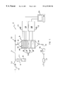
- FIG. 1 is a schematic side plan view of the unique and novel structure utilized to carry out the inventive method of the present invention
- FIG. 2 is an enlarged cross-sectional view of two aligned fluid flow-through conduits clamped together and which can be employed with the structure of FIG. 1 taken in a plane through line 2 — 2 of FIG. 3, the flow-through conduits being in the form of commercially available flow-through rings with extended peripheral flanges clamped together by a split, hinged clamping ring;
- FIG. 3 is an enlarged plan view of the hinged clamping ring of FIG. 2;
- FIG. 4 is an enlarged view of a portion of the filter sample arrangement as shown in FIGS. 2;
- FIG. 5 is an enlarged isometric view of a support screen one or more of which can be adjustably positioned in a flow-through conduit to support and adjust spacing between two or more filter media in the novel testing tower of FIG. 1;
- FIG. 6 is a partially broken away view of the schematic structure of FIG. 1, disclosing two aligned testing fluid filter media samples and back-up screen to be tested in assembled face-to-face relation in the novel testing tower of FIG. 1;
- FIG. 7 discloses a similar testing arrangement as FIG. 7 with the two filter media samples in preselected spaced relation in the testing tower, each having a facing, downstream back-up screen;
- FIG. 8 discloses a similar testing arrangement as FIG. 6, here the two filter media samples to be tested being spaced from each other with an intermediate screen-like spacer therebetween facing the upstream face of the downstream testing sample and a back-up screen facing the downstream face of such downstream testing sample;
- FIG. 9 discloses a similar testing arrangement as FIG. 7, here spaced, pleated filter media samples being shown, each with facing back-up screens;
- FIG. 10 discloses a schematic cross-sectional view of two pleated filter media samples which can be arranged to be tested in the testing tower of FIG. 1 with the crests in abutting relation;
- FIG. 11 is similar to the arrangement of FIG. 10, except that the crests of the two filter media samples to be tested are in crossing relation;
- FIG. 12 is also similar to the arrangement of FIG. 10, except that one filter media sample to be tested is pleated and the other sample to be spaced from the pleated sample is flat; and,
- FIG. 13 is similar to the arrangement of FIG. 7 but here three filter media test samples are disclosed in preselected spaced relation.
- FIG. 1 of the drawings which discloses a side plan view of the unique structure to carry out the present invention
- a comparative test stand arrangement 2 is disclosed for comparatively testing successive sample layers of fluid filter media of types presently known in the fluid filtration arts—as well as fluid filtration media yet to be developed.
- the present invention has particular applicability to the testing of numerous samples of air filter media, it is to be understood that the testing of other fluid filter media could also be successfully accomplished.
- the present invention has particular applicability to testing filter media samples of filter media arrangements such as employed in aforementioned Patent Application No. 08/996,222, filed on Dec. 22, 1997 by Kyung-Ju Choi, now U.S. Pat. No. 5,968,373.
- FIG. 1 of the drawings a longitudinally extending flow-through tower housing 3 is schematically disclosed as including an air test stream inlet 4 at the upstream end thereof and a downstream outlet 6 at the downstream end thereof.
- FIG. 1 discloses flow-through tower housing 3 with the flow axis disposed in a vertical position, it is to be understood that the flow-through housing flow axis can be positioned at other preselected angles, depending upon the nature of the selected commercial position of the filter media which are represented by the media samples to be tested.
- a parallel connected particle generator or nebulizer 8 Positioned upstream main compressed fluid line 7 , which is connected to tower housing inlet 4 , is a parallel connected particle generator or nebulizer 8 .
- Inlet line 9 connected to main compressed fluid line 7 at one end thereof has the opposite end connected to the particle generator or nebulizer 8 .
- An outlet line 11 parallel to and downstream of fluid line 9 , connects the particle generator 8 at one end thereof to main compressed fluid line 7 at the other end thereof.
- a high efficiency fluid filter (HEPA) 12 Upstream the parallel connected particle generator 8 and in series with main compressed fluid line 7 is a high efficiency fluid filter (HEPA) 12 .
- Suitable control valves 13 are provided upstream and downstream main compressed fluid line 7 and with particle counters described hereinafter.
- Downstream flow-through tower housing 3 is a main fluid outlet line 14 having a flow meter gauge 16 and an exhaust fluid outlet filter 17 connect in series with main fluid outlet line 14 .
- FIGS. 2-5 of the drawings and in accordance with one novel feature of the present invention unique structure can be seen for assembling the flow-through tower housing 3 disclosed in schematic FIG. 1 .
- This structure includes aligned flow-through spacer conduits in the form of modular incremental spacer rings 18 joined together by hinged clamps 19 (FIG. 2 - 4 ).
- Components as disclosed herein are commercially available as ISO-KF vacuum components, sold by MKS Instruments, Inc., Boulder, Colo. (see the above noted bulletin pages). It is to be understood that the present invention is not limited to the particular components disclosed herein and that the axial thicknesses thereof, as well as other types of commercially available components and latches could be utilized to assemble the tower housing 3 .
- each ring 18 (FIG. 2) is provided with peripheral end lips 21 , so that adjacent lips 21 of adjacent, aligned rings 18 can be engaged and surrounded by groove 22 extending along the inner periphery of hinged, split ring clamp 19 (FIGS. 3 and 4 ).
- a screw and thumb-bolt assembly 23 (FIG. 3 ), is utilized with split ring clamp 19 to hold the end lips 21 of adjacent aligned rings 18 together in fast relation.
- testing sample 24 includes an appropriately sized fluid filter media test sample 26 to be tested which is tightly sealed along the periphery thereof to a flexible, compressible ring border ring 27 , such as rubber, which is tightly clamped between adjacent peripheral end lips 21 of adjacent rings 18 .
- the clamping of rings 18 is accomplished by split clamping ring 19 and the screw and thumb-bolt assembly 23 .
- eight (8) such rings 18 and nine (9) clamping rings 19 are disclosed in the flow-through tower housing assembly 3 .
- the number of rings and clamps to be utilized can be varied in accordance with the number of fluid filter media testing samples to be tested and the preselected spacing between test samples.
- each ring 18 is connected by suitable connecting lines to one of two particle counters 28 , which in turn are connected by suitable connecting lines to a computer 29 .
- Particle counters 28 can be of the laser type, using laser diodes, such as Model 5230 made by HIAC/ROYCO, or other suitable particle counters commercially available.
- each of two adjacent and joined spacer rings 18 are connected to one of four differential pressure gauges 31 , each of which gauges serves to measure the pressure drop across a testing sample 24 which might be associated with spacer rings 18 .
- the multi-layer fluid filter media test stand above described is particularly adapted for an airstream and can accommodate particle sizes up to thirty (30) micrometers in diameter and air velocities up to one thousand (1000) feet per minute (ft/min.). Optimum particle sizes can range from approximately zero point three (0.3) to ten (10) micrometers and optimum air velocities can range from approximately five (5) to six hundred (600) feet per minute (ft/min.).
- the particle generator or nebulizer 8 can be a collision nebulizer made by BGI, located at Waltham, Mass. As an example, potassium chloride (KCI) or sodium chloride (NaCl) particles can be utilized.
- the data acquisition can be done by personal computer 29 and the pressure drop across each of the filter media test samples is measured by differential pressure gauges 31 , with air flow being measured by the orifice flow meter 16 .
- One of the key features of the test stand is its ability to handle multi-stationed test samples at preselected spacing between samples.
- cup sample support 34 includes an open, flow-through, low resistant, filter media support surface 35 and a compressible peripheral gasket 40 sized to firmly surround the rim and engage with the inner peripheries of one or more spacer rings 18 . It is to be understood that instead of adjustable cup sample support 34 , media sample peripheries can be sized and treated to be clamped between adjacent ring surfaces 18 in fixed position (FIGS. 2 and 4 ).
- This arrangement of filter 32 , 33 and cup support 34 is disposed in a face-to-face package relation in the novel testing tower housing 13 with the leads of differential pressure gauge 31 and particle counters 28 being positioned on the upstream and downstream side of the package to determine pressure drop, fiber sizing, and spacing requirements of the arrangement.
- FIG. 7 a similar flat filter media sample 36 and a facing downstream screen 37 is shown as an upstream first package in test housing 13 and preselectively spaced therefrom in test housing 13 is flat filter media sample 38 and another facing downstream filter media support 39 as a second package.
- the leads of two differential pressure gauges 31 and two particle counters 28 are respectively positioned on the upstream and downstream face of each first and second package to determine appropriate pressure drop, fiber sizing and spacing of the arrangement.
- FIG. 8 two preselectively spaced flat filter media test samples 41 and 42 , with downstream sample 42 supported by facing downstream flat filter media support 44 , the samples being shown in aligned, spaced position in tower housing 13 with a spacer 46 such as plastic netting or open scrim material therebetween and with the lines of differential pressure gauges 31 and particle counters 28 being selectively positioned upstream and downstream of selected parts of the assembly.
- FIG. 9 is similar to FIG. 7, only pleated sample test media supported by filter media supports 49 and 51 are shown as respectively spaced first and second packages disposed in tower test housing 13 with the leads for particle counters 28 and differential pressure gauges 31 being connected to the upstream and downstream faces of each first and second packages.
- Still another two filter media supports testing arrangements can be seen in FIGS. 10 and 11.
- testing media pleated samples 52 and 53 can be arranged for support and testing in housing 13 in crest abutting relationship or, as shown in FIG. 11, pleated samples 54 and 56 can be arranged in crest crossing relationship when supportedly disposed in test housing 13
- FIG. 12 an arrangement is disclosed wherein pleated filter media test sample 58 is positioned in aligned spaced relation from flat filter media test sample 59 as shown.
- FIG. 13 three spaced flat filter media test samples 61 , 62 , and 63 are shown in a spaced relative arrangement for testing in tower housing 13 .
- the novel test stand structure allows for numerous testing combinations, all in accordance with the novel disclosure as set forth in the aforementioned U.S. Pat. No. 5,968,373, issued on Oct. 19, 1999, to Kyung-Ju Choi.
- this prior patent several different novel and inventive arrangements of filter media are described and the present application presents an inventive comparative testing method of filter media samples compatible with the teachings of the prior application and in which the several steps of such novel method can be accomplished with the above-described unique and novel apparatus, allowing a determination of appropriate fiber sizing, media contour, spacing and pressure drop control.
- At least two sample layers of filter media which correspond to those to be utilized for filtering purposes are successively positioned in a fluid confined flow-through test zone in a decreasing average pore size arrangement, the test zone including an upstream inlet and downstream outlet with the sample layers of filter media disposed in the confined zone between upstream inlet and downstream outlet so as to be in preselected relation to each other and to extend transversely across the line of fluid flow-though the confined zone with the edges of the filter media sample layers in sealed relation with the confined zone.
- a measured particle laden fluid having first been passed through a high efficiency filtering zone, is then introduced into the upstream inlet of the confined zone, the particle count which can be accomplished optically is measured upstream and downstream each sample layer, as is the differential pressure between the upstream and downstream side of each sample layer.
- the measured particles can be introduced into the test zone by compressed fluid, such as air, passing through a suitable particle generating zone with the fluid being metered in a flow metering zone downstream the confined flow-through test zone so as to meter the cubic feet per minute of fluid flow through the confined flow-through test zone.
- compressed fluid such as air
- testing can be accomplished in the flow-through test zone in any one of the several test sample arrangements as disclosed in FIGS. 7-14 or in other possible arrangements as the commercial situation to be met might dictate.
- fluid particle flow can also be accomplished (not shown) by utilizing an appropriate vacuum adjacent the downstream outlet of tower 13 or by a combination of compression and vacuum.
- testing stations are disclosed in the embodiment of FIG. 1, a higher or lower number of testing stations can be employed, as the commercial situation might dictate and within the physical limits of the testing equipment.
Abstract
Description
Claims (23)
Priority Applications (1)
| Application Number | Priority Date | Filing Date | Title |
|---|---|---|---|
| US09/454,852 US6327893B1 (en) | 1999-12-07 | 1999-12-07 | Filter layer comparative testing method and apparatus |
Applications Claiming Priority (1)
| Application Number | Priority Date | Filing Date | Title |
|---|---|---|---|
| US09/454,852 US6327893B1 (en) | 1999-12-07 | 1999-12-07 | Filter layer comparative testing method and apparatus |
Publications (1)
| Publication Number | Publication Date |
|---|---|
| US6327893B1 true US6327893B1 (en) | 2001-12-11 |
Family
ID=23806360
Family Applications (1)
| Application Number | Title | Priority Date | Filing Date |
|---|---|---|---|
| US09/454,852 Expired - Fee Related US6327893B1 (en) | 1999-12-07 | 1999-12-07 | Filter layer comparative testing method and apparatus |
Country Status (1)
| Country | Link |
|---|---|
| US (1) | US6327893B1 (en) |
Cited By (8)
| Publication number | Priority date | Publication date | Assignee | Title |
|---|---|---|---|---|
| US20060112757A1 (en) * | 2004-11-29 | 2006-06-01 | Morse Thomas C | Filter housing assembly with leak testable aerosol injection port |
| US20060188994A1 (en) * | 2005-02-23 | 2006-08-24 | Hunter Manufacturing Co. | Filter integrity tester |
| US20070079649A1 (en) * | 2005-10-11 | 2007-04-12 | Millipore Corporation | Integrity testable multilayered filter device |
| EP1779913A2 (en) * | 2005-10-21 | 2007-05-02 | Millipore Corporation | Filtration device and process for testing filtration material in a filtration device |
| US20080210879A1 (en) * | 2005-07-11 | 2008-09-04 | Maintenance Securite Installation Service | Method for Controlling Leakage Rate of Active Carbon Filters |
| US20160299048A1 (en) * | 2015-04-08 | 2016-10-13 | Emd Millipore Corporation | Enhanced Aerosol Test For Assessing Filter Integrity |
| JP2021085839A (en) * | 2019-11-29 | 2021-06-03 | 株式会社日立製作所 | Filter inspection system and filter inspection method in particulate analyzer |
| EP4139654A4 (en) * | 2020-07-08 | 2024-01-03 | Corning Inc | Offline measurement of honeycomb body filtration efficiency |
Citations (26)
| Publication number | Priority date | Publication date | Assignee | Title |
|---|---|---|---|---|
| US3276597A (en) * | 1963-11-06 | 1966-10-04 | Johnson & Johnson | Filter media |
| US3614421A (en) * | 1968-12-12 | 1971-10-19 | Gen Electric | Ambient radioactivity air filter tester using a track-registration material |
| US3810697A (en) | 1972-08-10 | 1974-05-14 | Air Technologies Inc | Portable filter evaluation apparatus |
| FR2252785A5 (en) * | 1973-11-27 | 1975-06-20 | Sindetec | Filters in series grade suspended particles into size ranges - for biological medical, quality control and contamination tests of liquids |
| US4055075A (en) * | 1976-04-08 | 1977-10-25 | Flanders Filters, Inc. | Method and apparatus for the leak testing of filters |
| US4157968A (en) * | 1977-02-12 | 1979-06-12 | Ultrafilter Gmbh | Filters |
| US4213768A (en) | 1978-11-27 | 1980-07-22 | Bauman Albert J | Nondestructive testing of HEPA filters |
| US4279508A (en) | 1979-06-29 | 1981-07-21 | Everroad Herbert L | Method and apparatus for testing air filters and the like |
| US4324568A (en) * | 1980-08-11 | 1982-04-13 | Flanders Filters, Inc. | Method and apparatus for the leak testing of filters |
| US4384474A (en) * | 1980-10-30 | 1983-05-24 | Amf Incorporated | Method and apparatus for testing and using membrane filters in an on site of use housing |
| US4387993A (en) | 1981-06-25 | 1983-06-14 | Tsi Incorporated | Particle size measuring method and apparatus |
| US4446099A (en) * | 1980-07-31 | 1984-05-01 | Framatome | Device for protecting control cluster actuating mechanisms during the testing of a nuclear reactor |
| US4494403A (en) | 1982-07-14 | 1985-01-22 | Flanders Filters, Inc. | Filter testing apparatus and method |
| US4515007A (en) * | 1983-01-04 | 1985-05-07 | The United States Of America As Represented By The United States Department Of Energy | Method of and apparatus for testing the integrity of filters |
| EP0150266A2 (en) * | 1979-03-05 | 1985-08-07 | Flanders Filters, Inc. | Method and apparatus for the leak testing of filters |
| US4610705A (en) * | 1984-11-06 | 1986-09-09 | Broan Manufacturing Co. Inc. | Filter for ductless range hood |
| US4619136A (en) * | 1985-07-03 | 1986-10-28 | The United States Of America As Represented By The United States Department Of Energy | Apparatus for measuring the decontamination factor of a multiple filter air-cleaning system |
| US4646558A (en) * | 1983-11-10 | 1987-03-03 | Cambridge Filter Corp. | Method for leak testing air filters |
| US4686848A (en) * | 1984-11-20 | 1987-08-18 | Umec Corporation | High temperature particulate filter media test unit |
| US4772390A (en) * | 1982-01-25 | 1988-09-20 | Mitsubishi Rayon Co., Ltd. | Water purifying method and system |
| JPS63311145A (en) | 1987-06-12 | 1988-12-19 | Nippon Kagaku Kogyo Kk | Collecting-efficiency measuring apparatus of air filter |
| US5203201A (en) | 1991-12-20 | 1993-04-20 | Donaldson Company, Inc. | On-line web filtration efficiency test method |
| US5244480A (en) | 1991-11-01 | 1993-09-14 | Henry Harold G | High efficiency particulate air filter ventilation system with air conditioning unit and environmental monitoring unit |
| US5351523A (en) * | 1993-01-21 | 1994-10-04 | Tsi Incorporated | Apparatus and process for determining filter efficiency in removing colloidal suspensions |
| US5488811A (en) | 1995-02-21 | 1996-02-06 | Abbott Laboratories | On-line air filter integrity testing apparatus |
| US5968373A (en) | 1997-12-22 | 1999-10-19 | Aaf International | Filter arrangement having at least two successive layers having predetermined spacing and its method for making |
-
1999
- 1999-12-07 US US09/454,852 patent/US6327893B1/en not_active Expired - Fee Related
Patent Citations (27)
| Publication number | Priority date | Publication date | Assignee | Title |
|---|---|---|---|---|
| US3276597A (en) * | 1963-11-06 | 1966-10-04 | Johnson & Johnson | Filter media |
| US3614421A (en) * | 1968-12-12 | 1971-10-19 | Gen Electric | Ambient radioactivity air filter tester using a track-registration material |
| US3810697A (en) | 1972-08-10 | 1974-05-14 | Air Technologies Inc | Portable filter evaluation apparatus |
| FR2252785A5 (en) * | 1973-11-27 | 1975-06-20 | Sindetec | Filters in series grade suspended particles into size ranges - for biological medical, quality control and contamination tests of liquids |
| US4055075A (en) * | 1976-04-08 | 1977-10-25 | Flanders Filters, Inc. | Method and apparatus for the leak testing of filters |
| US4157968B1 (en) * | 1977-02-12 | 1984-06-05 | ||
| US4157968A (en) * | 1977-02-12 | 1979-06-12 | Ultrafilter Gmbh | Filters |
| US4213768A (en) | 1978-11-27 | 1980-07-22 | Bauman Albert J | Nondestructive testing of HEPA filters |
| EP0150266A2 (en) * | 1979-03-05 | 1985-08-07 | Flanders Filters, Inc. | Method and apparatus for the leak testing of filters |
| US4279508A (en) | 1979-06-29 | 1981-07-21 | Everroad Herbert L | Method and apparatus for testing air filters and the like |
| US4446099A (en) * | 1980-07-31 | 1984-05-01 | Framatome | Device for protecting control cluster actuating mechanisms during the testing of a nuclear reactor |
| US4324568A (en) * | 1980-08-11 | 1982-04-13 | Flanders Filters, Inc. | Method and apparatus for the leak testing of filters |
| US4384474A (en) * | 1980-10-30 | 1983-05-24 | Amf Incorporated | Method and apparatus for testing and using membrane filters in an on site of use housing |
| US4387993A (en) | 1981-06-25 | 1983-06-14 | Tsi Incorporated | Particle size measuring method and apparatus |
| US4772390A (en) * | 1982-01-25 | 1988-09-20 | Mitsubishi Rayon Co., Ltd. | Water purifying method and system |
| US4494403A (en) | 1982-07-14 | 1985-01-22 | Flanders Filters, Inc. | Filter testing apparatus and method |
| US4515007A (en) * | 1983-01-04 | 1985-05-07 | The United States Of America As Represented By The United States Department Of Energy | Method of and apparatus for testing the integrity of filters |
| US4646558A (en) * | 1983-11-10 | 1987-03-03 | Cambridge Filter Corp. | Method for leak testing air filters |
| US4610705A (en) * | 1984-11-06 | 1986-09-09 | Broan Manufacturing Co. Inc. | Filter for ductless range hood |
| US4686848A (en) * | 1984-11-20 | 1987-08-18 | Umec Corporation | High temperature particulate filter media test unit |
| US4619136A (en) * | 1985-07-03 | 1986-10-28 | The United States Of America As Represented By The United States Department Of Energy | Apparatus for measuring the decontamination factor of a multiple filter air-cleaning system |
| JPS63311145A (en) | 1987-06-12 | 1988-12-19 | Nippon Kagaku Kogyo Kk | Collecting-efficiency measuring apparatus of air filter |
| US5244480A (en) | 1991-11-01 | 1993-09-14 | Henry Harold G | High efficiency particulate air filter ventilation system with air conditioning unit and environmental monitoring unit |
| US5203201A (en) | 1991-12-20 | 1993-04-20 | Donaldson Company, Inc. | On-line web filtration efficiency test method |
| US5351523A (en) * | 1993-01-21 | 1994-10-04 | Tsi Incorporated | Apparatus and process for determining filter efficiency in removing colloidal suspensions |
| US5488811A (en) | 1995-02-21 | 1996-02-06 | Abbott Laboratories | On-line air filter integrity testing apparatus |
| US5968373A (en) | 1997-12-22 | 1999-10-19 | Aaf International | Filter arrangement having at least two successive layers having predetermined spacing and its method for making |
Non-Patent Citations (1)
| Title |
|---|
| Sindetec, Process and Device for Determining the Distribution by Size of Particles in Suspension in a Liquid, translation, May, 2001. * |
Cited By (18)
| Publication number | Priority date | Publication date | Assignee | Title |
|---|---|---|---|---|
| US7186286B2 (en) * | 2004-11-29 | 2007-03-06 | Camfil Farr, Inc. | Filter housing assembly with leak testable aerosol injection port |
| US20060112757A1 (en) * | 2004-11-29 | 2006-06-01 | Morse Thomas C | Filter housing assembly with leak testable aerosol injection port |
| US20060188994A1 (en) * | 2005-02-23 | 2006-08-24 | Hunter Manufacturing Co. | Filter integrity tester |
| US7592178B2 (en) | 2005-02-23 | 2009-09-22 | Hunter Menufacturing Co. | Filter integrity tester |
| US20080210879A1 (en) * | 2005-07-11 | 2008-09-04 | Maintenance Securite Installation Service | Method for Controlling Leakage Rate of Active Carbon Filters |
| JP2007105725A (en) * | 2005-10-11 | 2007-04-26 | Millipore Corp | Multi-layered filtration device allowing integrity test |
| US20070079649A1 (en) * | 2005-10-11 | 2007-04-12 | Millipore Corporation | Integrity testable multilayered filter device |
| US7650805B2 (en) | 2005-10-11 | 2010-01-26 | Millipore Corporation | Integrity testable multilayered filter device |
| EP1779913A2 (en) * | 2005-10-21 | 2007-05-02 | Millipore Corporation | Filtration device and process for testing filtration material in a filtration device |
| EP1779913A3 (en) * | 2005-10-21 | 2009-04-01 | Millipore Corporation | Filtration device and process for testing filtration material in a filtration device |
| CN101703853B (en) * | 2005-10-21 | 2013-11-06 | Emd密理博公司 | Multi-layered filtration device allowing integrity test |
| US20160299048A1 (en) * | 2015-04-08 | 2016-10-13 | Emd Millipore Corporation | Enhanced Aerosol Test For Assessing Filter Integrity |
| CN106053104A (en) * | 2015-04-08 | 2016-10-26 | Emd密理博公司 | Enhanced Aerosol Test For Assessing Filter Integrity |
| US10151679B2 (en) * | 2015-04-08 | 2018-12-11 | Emd Millipore Corporation | Enhanced aerosol test for assessing filter integrity |
| CN113670788A (en) * | 2015-04-08 | 2021-11-19 | Emd密理博公司 | Enhanced aerosol test for evaluating filter integrity |
| JP2021085839A (en) * | 2019-11-29 | 2021-06-03 | 株式会社日立製作所 | Filter inspection system and filter inspection method in particulate analyzer |
| WO2021106426A1 (en) * | 2019-11-29 | 2021-06-03 | 株式会社日立製作所 | Filter inspection system and filter inspection method for fine particle analysis device |
| EP4139654A4 (en) * | 2020-07-08 | 2024-01-03 | Corning Inc | Offline measurement of honeycomb body filtration efficiency |
Similar Documents
| Publication | Publication Date | Title |
|---|---|---|
| US11826689B2 (en) | Air filter arrangement; assembly; and, methods | |
| EP3237089B1 (en) | Air cleaner assembly and filter cartridge | |
| JP6349363B6 (en) | Air cleaner | |
| US9527027B2 (en) | Filter assembly; components therefor; and, methods | |
| US6327893B1 (en) | Filter layer comparative testing method and apparatus | |
| EP3135363B1 (en) | Air filter arrangement; assembly; and, methods | |
| US6113674A (en) | Adsorption apparatus and methods | |
| US8328897B2 (en) | Air cleaner arrangement; assembly; and, methods | |
| US6916360B2 (en) | Adsorption methods | |
| US7967898B2 (en) | Z-filter media with reverse-flow cleaning systems and methods | |
| CA2904320A1 (en) | Filtration system for a gas turbine air intake and methods | |
| JP2003510744A (en) | Rigid multifunctional filter assembly | |
| US6672135B2 (en) | Filter for gas analysis | |
| US20210046415A1 (en) | Filter element, systems, and methods | |
| MX2007008538A (en) | Air filter cartridge and air cleaner assembly. | |
| CN106769766A (en) | Cylinder air purifying filter element performance evaluation detector | |
| CN201534030U (en) | Oil gas filtering and separating device | |
| JP7397428B2 (en) | Multiple sampler device | |
| CA2145047A1 (en) | Fluid filter and method of separating entrained particulate matter from a moving fluid stream | |
| JPS60193519A (en) | Oil removing apparatus | |
| SE544716C2 (en) | Pleated filter element with different pleat heights and air filters comprising the filter element | |
| JPH10244116A (en) | Collecting efficiency measuring device for filter medium of air filter | |
| Duran | Improvement of flow uniformity and modeling of filtration efficiencies for automotive air filter test housings | |
| RU2239815C1 (en) | Cascade impactor | |
| CN112780564A (en) | Purification structure and compressor |
Legal Events
| Date | Code | Title | Description |
|---|---|---|---|
| AS | Assignment |
Owner name: AAF-MCQUAY, KENTUCKY Free format text: ASSIGNMENT OF ASSIGNORS INTEREST;ASSIGNOR:CHOI, KYUNG-JU;REEL/FRAME:011499/0871 Effective date: 20001227 |
|
| AS | Assignment |
Owner name: BANK OF AMERICA, N.A., AS COLLATERAL AGENT, ILLINO Free format text: NOTICE OF GRANT OF SECURITY INTEREST;ASSIGNOR:AAF-MCQUAY INTERNATIONAL, INC.;REEL/FRAME:013599/0324 Effective date: 20021205 Owner name: BANK OF AMERICA, N.A., AS COLLATERAL AGENT, ILLINO Free format text: NOTICE OF GRANT OF SECURITY INTEREST;ASSIGNOR:AAF-MCQUAY, INC,;REEL/FRAME:013599/0342 Effective date: 20021205 |
|
| FPAY | Fee payment |
Year of fee payment: 4 |
|
| FPAY | Fee payment |
Year of fee payment: 8 |
|
| SULP | Surcharge for late payment |
Year of fee payment: 7 |
|
| FEPP | Fee payment procedure |
Free format text: PAYOR NUMBER ASSIGNED (ORIGINAL EVENT CODE: ASPN); ENTITY STATUS OF PATENT OWNER: LARGE ENTITY |
|
| REMI | Maintenance fee reminder mailed | ||
| LAPS | Lapse for failure to pay maintenance fees | ||
| STCH | Information on status: patent discontinuation |
Free format text: PATENT EXPIRED DUE TO NONPAYMENT OF MAINTENANCE FEES UNDER 37 CFR 1.362 |
|
| FP | Lapsed due to failure to pay maintenance fee |
Effective date: 20131211 |