US6328446B1 - Production of optical elements - Google Patents
Production of optical elements Download PDFInfo
- Publication number
- US6328446B1 US6328446B1 US09/425,517 US42551799A US6328446B1 US 6328446 B1 US6328446 B1 US 6328446B1 US 42551799 A US42551799 A US 42551799A US 6328446 B1 US6328446 B1 US 6328446B1
- Authority
- US
- United States
- Prior art keywords
- lens
- functional
- layer
- ophthalmic
- photochromic
- Prior art date
- Legal status (The legal status is an assumption and is not a legal conclusion. Google has not performed a legal analysis and makes no representation as to the accuracy of the status listed.)
- Expired - Lifetime
Links
Images


Classifications
-
- B—PERFORMING OPERATIONS; TRANSPORTING
- B32—LAYERED PRODUCTS
- B32B—LAYERED PRODUCTS, i.e. PRODUCTS BUILT-UP OF STRATA OF FLAT OR NON-FLAT, e.g. CELLULAR OR HONEYCOMB, FORM
- B32B7/00—Layered products characterised by the relation between layers; Layered products characterised by the relative orientation of features between layers, or by the relative values of a measurable parameter between layers, i.e. products comprising layers having different physical, chemical or physicochemical properties; Layered products characterised by the interconnection of layers
- B32B7/04—Interconnection of layers
- B32B7/12—Interconnection of layers using interposed adhesives or interposed materials with bonding properties
-
- B—PERFORMING OPERATIONS; TRANSPORTING
- B29—WORKING OF PLASTICS; WORKING OF SUBSTANCES IN A PLASTIC STATE IN GENERAL
- B29C—SHAPING OR JOINING OF PLASTICS; SHAPING OF MATERIAL IN A PLASTIC STATE, NOT OTHERWISE PROVIDED FOR; AFTER-TREATMENT OF THE SHAPED PRODUCTS, e.g. REPAIRING
- B29C45/00—Injection moulding, i.e. forcing the required volume of moulding material through a nozzle into a closed mould; Apparatus therefor
- B29C45/14—Injection moulding, i.e. forcing the required volume of moulding material through a nozzle into a closed mould; Apparatus therefor incorporating preformed parts or layers, e.g. injection moulding around inserts or for coating articles
- B29C45/14778—Injection moulding, i.e. forcing the required volume of moulding material through a nozzle into a closed mould; Apparatus therefor incorporating preformed parts or layers, e.g. injection moulding around inserts or for coating articles the article consisting of a material with particular properties, e.g. porous, brittle
- B29C45/14811—Multilayered articles
-
- B—PERFORMING OPERATIONS; TRANSPORTING
- B29—WORKING OF PLASTICS; WORKING OF SUBSTANCES IN A PLASTIC STATE IN GENERAL
- B29D—PRODUCING PARTICULAR ARTICLES FROM PLASTICS OR FROM SUBSTANCES IN A PLASTIC STATE
- B29D11/00—Producing optical elements, e.g. lenses or prisms
- B29D11/00009—Production of simple or compound lenses
- B29D11/00028—Bifocal lenses; Multifocal lenses
-
- B—PERFORMING OPERATIONS; TRANSPORTING
- B29—WORKING OF PLASTICS; WORKING OF SUBSTANCES IN A PLASTIC STATE IN GENERAL
- B29D—PRODUCING PARTICULAR ARTICLES FROM PLASTICS OR FROM SUBSTANCES IN A PLASTIC STATE
- B29D11/00—Producing optical elements, e.g. lenses or prisms
- B29D11/0073—Optical laminates
-
- B—PERFORMING OPERATIONS; TRANSPORTING
- B32—LAYERED PRODUCTS
- B32B—LAYERED PRODUCTS, i.e. PRODUCTS BUILT-UP OF STRATA OF FLAT OR NON-FLAT, e.g. CELLULAR OR HONEYCOMB, FORM
- B32B27/00—Layered products comprising a layer of synthetic resin
-
- B—PERFORMING OPERATIONS; TRANSPORTING
- B32—LAYERED PRODUCTS
- B32B—LAYERED PRODUCTS, i.e. PRODUCTS BUILT-UP OF STRATA OF FLAT OR NON-FLAT, e.g. CELLULAR OR HONEYCOMB, FORM
- B32B27/00—Layered products comprising a layer of synthetic resin
- B32B27/06—Layered products comprising a layer of synthetic resin as the main or only constituent of a layer, which is next to another layer of the same or of a different material
- B32B27/08—Layered products comprising a layer of synthetic resin as the main or only constituent of a layer, which is next to another layer of the same or of a different material of synthetic resin
-
- B—PERFORMING OPERATIONS; TRANSPORTING
- B32—LAYERED PRODUCTS
- B32B—LAYERED PRODUCTS, i.e. PRODUCTS BUILT-UP OF STRATA OF FLAT OR NON-FLAT, e.g. CELLULAR OR HONEYCOMB, FORM
- B32B27/00—Layered products comprising a layer of synthetic resin
- B32B27/30—Layered products comprising a layer of synthetic resin comprising vinyl (co)polymers; comprising acrylic (co)polymers
- B32B27/304—Layered products comprising a layer of synthetic resin comprising vinyl (co)polymers; comprising acrylic (co)polymers comprising vinyl halide (co)polymers, e.g. PVC, PVDC, PVF, PVDF
-
- B—PERFORMING OPERATIONS; TRANSPORTING
- B32—LAYERED PRODUCTS
- B32B—LAYERED PRODUCTS, i.e. PRODUCTS BUILT-UP OF STRATA OF FLAT OR NON-FLAT, e.g. CELLULAR OR HONEYCOMB, FORM
- B32B27/00—Layered products comprising a layer of synthetic resin
- B32B27/30—Layered products comprising a layer of synthetic resin comprising vinyl (co)polymers; comprising acrylic (co)polymers
- B32B27/306—Layered products comprising a layer of synthetic resin comprising vinyl (co)polymers; comprising acrylic (co)polymers comprising vinyl acetate or vinyl alcohol (co)polymers
-
- B—PERFORMING OPERATIONS; TRANSPORTING
- B32—LAYERED PRODUCTS
- B32B—LAYERED PRODUCTS, i.e. PRODUCTS BUILT-UP OF STRATA OF FLAT OR NON-FLAT, e.g. CELLULAR OR HONEYCOMB, FORM
- B32B27/00—Layered products comprising a layer of synthetic resin
- B32B27/32—Layered products comprising a layer of synthetic resin comprising polyolefins
-
- B—PERFORMING OPERATIONS; TRANSPORTING
- B32—LAYERED PRODUCTS
- B32B—LAYERED PRODUCTS, i.e. PRODUCTS BUILT-UP OF STRATA OF FLAT OR NON-FLAT, e.g. CELLULAR OR HONEYCOMB, FORM
- B32B27/00—Layered products comprising a layer of synthetic resin
- B32B27/34—Layered products comprising a layer of synthetic resin comprising polyamides
-
- B—PERFORMING OPERATIONS; TRANSPORTING
- B32—LAYERED PRODUCTS
- B32B—LAYERED PRODUCTS, i.e. PRODUCTS BUILT-UP OF STRATA OF FLAT OR NON-FLAT, e.g. CELLULAR OR HONEYCOMB, FORM
- B32B27/00—Layered products comprising a layer of synthetic resin
- B32B27/36—Layered products comprising a layer of synthetic resin comprising polyesters
- B32B27/365—Layered products comprising a layer of synthetic resin comprising polyesters comprising polycarbonates
-
- G—PHYSICS
- G02—OPTICS
- G02C—SPECTACLES; SUNGLASSES OR GOGGLES INSOFAR AS THEY HAVE THE SAME FEATURES AS SPECTACLES; CONTACT LENSES
- G02C7/00—Optical parts
- G02C7/02—Lenses; Lens systems ; Methods of designing lenses
- G02C7/06—Lenses; Lens systems ; Methods of designing lenses bifocal; multifocal ; progressive
-
- G—PHYSICS
- G02—OPTICS
- G02C—SPECTACLES; SUNGLASSES OR GOGGLES INSOFAR AS THEY HAVE THE SAME FEATURES AS SPECTACLES; CONTACT LENSES
- G02C7/00—Optical parts
- G02C7/12—Polarisers
-
- B—PERFORMING OPERATIONS; TRANSPORTING
- B29—WORKING OF PLASTICS; WORKING OF SUBSTANCES IN A PLASTIC STATE IN GENERAL
- B29K—INDEXING SCHEME ASSOCIATED WITH SUBCLASSES B29B, B29C OR B29D, RELATING TO MOULDING MATERIALS OR TO MATERIALS FOR MOULDS, REINFORCEMENTS, FILLERS OR PREFORMED PARTS, e.g. INSERTS
- B29K2995/00—Properties of moulding materials, reinforcements, fillers, preformed parts or moulds
- B29K2995/0018—Properties of moulding materials, reinforcements, fillers, preformed parts or moulds having particular optical properties, e.g. fluorescent or phosphorescent
- B29K2995/0034—Polarising
-
- B—PERFORMING OPERATIONS; TRANSPORTING
- B29—WORKING OF PLASTICS; WORKING OF SUBSTANCES IN A PLASTIC STATE IN GENERAL
- B29L—INDEXING SCHEME ASSOCIATED WITH SUBCLASS B29C, RELATING TO PARTICULAR ARTICLES
- B29L2011/00—Optical elements, e.g. lenses, prisms
- B29L2011/0016—Lenses
-
- B—PERFORMING OPERATIONS; TRANSPORTING
- B29—WORKING OF PLASTICS; WORKING OF SUBSTANCES IN A PLASTIC STATE IN GENERAL
- B29L—INDEXING SCHEME ASSOCIATED WITH SUBCLASS B29C, RELATING TO PARTICULAR ARTICLES
- B29L2011/00—Optical elements, e.g. lenses, prisms
- B29L2011/0016—Lenses
- B29L2011/0033—Multifocal lenses
-
- B—PERFORMING OPERATIONS; TRANSPORTING
- B32—LAYERED PRODUCTS
- B32B—LAYERED PRODUCTS, i.e. PRODUCTS BUILT-UP OF STRATA OF FLAT OR NON-FLAT, e.g. CELLULAR OR HONEYCOMB, FORM
- B32B2323/00—Polyalkenes
- B32B2323/04—Polyethylene
-
- B—PERFORMING OPERATIONS; TRANSPORTING
- B32—LAYERED PRODUCTS
- B32B—LAYERED PRODUCTS, i.e. PRODUCTS BUILT-UP OF STRATA OF FLAT OR NON-FLAT, e.g. CELLULAR OR HONEYCOMB, FORM
- B32B2323/00—Polyalkenes
- B32B2323/10—Polypropylene
-
- B—PERFORMING OPERATIONS; TRANSPORTING
- B32—LAYERED PRODUCTS
- B32B—LAYERED PRODUCTS, i.e. PRODUCTS BUILT-UP OF STRATA OF FLAT OR NON-FLAT, e.g. CELLULAR OR HONEYCOMB, FORM
- B32B2325/00—Polymers of vinyl-aromatic compounds, e.g. polystyrene
-
- B—PERFORMING OPERATIONS; TRANSPORTING
- B32—LAYERED PRODUCTS
- B32B—LAYERED PRODUCTS, i.e. PRODUCTS BUILT-UP OF STRATA OF FLAT OR NON-FLAT, e.g. CELLULAR OR HONEYCOMB, FORM
- B32B2327/00—Polyvinylhalogenides
- B32B2327/06—PVC, i.e. polyvinylchloride
-
- B—PERFORMING OPERATIONS; TRANSPORTING
- B32—LAYERED PRODUCTS
- B32B—LAYERED PRODUCTS, i.e. PRODUCTS BUILT-UP OF STRATA OF FLAT OR NON-FLAT, e.g. CELLULAR OR HONEYCOMB, FORM
- B32B2331/00—Polyvinylesters
- B32B2331/04—Polymers of vinyl acetate, e.g. PVA
-
- B—PERFORMING OPERATIONS; TRANSPORTING
- B32—LAYERED PRODUCTS
- B32B—LAYERED PRODUCTS, i.e. PRODUCTS BUILT-UP OF STRATA OF FLAT OR NON-FLAT, e.g. CELLULAR OR HONEYCOMB, FORM
- B32B2369/00—Polycarbonates
-
- B—PERFORMING OPERATIONS; TRANSPORTING
- B32—LAYERED PRODUCTS
- B32B—LAYERED PRODUCTS, i.e. PRODUCTS BUILT-UP OF STRATA OF FLAT OR NON-FLAT, e.g. CELLULAR OR HONEYCOMB, FORM
- B32B2377/00—Polyamides
-
- B—PERFORMING OPERATIONS; TRANSPORTING
- B32—LAYERED PRODUCTS
- B32B—LAYERED PRODUCTS, i.e. PRODUCTS BUILT-UP OF STRATA OF FLAT OR NON-FLAT, e.g. CELLULAR OR HONEYCOMB, FORM
- B32B2398/00—Unspecified macromolecular compounds
- B32B2398/20—Thermoplastics
-
- Y—GENERAL TAGGING OF NEW TECHNOLOGICAL DEVELOPMENTS; GENERAL TAGGING OF CROSS-SECTIONAL TECHNOLOGIES SPANNING OVER SEVERAL SECTIONS OF THE IPC; TECHNICAL SUBJECTS COVERED BY FORMER USPC CROSS-REFERENCE ART COLLECTIONS [XRACs] AND DIGESTS
- Y10—TECHNICAL SUBJECTS COVERED BY FORMER USPC
- Y10T—TECHNICAL SUBJECTS COVERED BY FORMER US CLASSIFICATION
- Y10T428/00—Stock material or miscellaneous articles
- Y10T428/31504—Composite [nonstructural laminate]
Definitions
- the present invention relates to optical elements and to methods of making optical elements. More specifically, the present invention relates to an optical element that incorporates a laminate to provide a functional property and to a method of incorporating the functional property in the optical element by adherence of the laminate to an optical power lens element.
- thermoset resins and polymers such as allyl diglycol carbonate, one brand of which is sold under the CR-39® trademark of PPG Industries, Inc.
- thermoplastic materials and polymers such as polycarbonate polymers.
- Polycarbonate is an amorphous, thermoplastic material that has mechanical properties that are very desirable for ophthalmic lenses.
- ophthalmic lenses made of polycarbonate have unusually high impact resistance and strength which make the lenses surprisingly shatter-resistant.
- the relatively low specific gravity of polycarbonate makes it possible to significantly decrease the weight of polycarbonate lenses, as compared to glass or CR-39® lenses.
- Polycarbonate is highly transparent and has a desirably high refractive index for ophthalmic lens applications.
- the good thermal properties of molten polycarbonate makes the material conducive to efficient processing by conventional techniques, such as injection molding.
- U.S. Pat. No. 3,786,119 to Ortlieb discloses a laminated plate of polarizing plastic material that is formed into a polarizing screen. The polarizing screen is placed within a mold which is filled with polymerizable or polycondensible liquid resin.
- U.S. Pat. No. 3,846,013 discloses a light-polarizing element formed by sandwiching light-polarizing material between thin layers of optical quality transparent polymeric material. The light-polarizing element is placed within a mold, and a polymerizable monomer is placed in the mold on either side of the light-polarizing element.
- U.S. Pat. No. 3,940,304 to Schuler discloses a shaped light-polarizing synthetic plastic member that is disposed between layers of an optical quality synthetic monomeric material in a mold. A monomeric material is placed within the mold and polymerized to form a composite synthetic plastic light-polarizing lens structure.
- U.S. Pat. No. 4,873,029 to Blum discloses a plastic wafer that may include polarizing features. The plastic wafer is inserted into a mold between liquid monomer molding material. The mold is then subjected to oven-curing to polymerize the liquid monomer.
- U.S. Pat. No. 5,286,419 to van Ligten et al. discloses a shaped polarizing film that is embedded in pre-gelled resin. The resin is cured to form a light polarizing lens.
- U.S. Pat. No. 5,051,309 to Kawaki et al. concerns a polarizing plate that is made by laminating polycarbonate film on both sides of a polarizing thin layer.
- the polarizing thin layer is composed of a polymeric film and a dichroic dye oriented on the polymeric film.
- suitable uses of the polarizing plate include goggles and sunglasses.
- the polarizing plate of U.S. Pat. No. 5,051,309 would not be suitable for use as an optical lens capable of meeting ophthalmic prescription specifications.
- the polycarbonate film included in the polarizing plate of this patent lacks the material integrity needed for successful grinding and polishing of polycarbonate optical elements to prescription specifications.
- Polycarbonate that is ground and polished to make optical elements must have sufficient material integrity to withstand the heat and pressure generated during grinding and polishing operations.
- the lack of material integrity of the polycarbonate film used in the Kawaki polarizing plate would affect cosmetic properties, as well as, the impact strength of any prescription specification optical elements made by grinding and polishing the polycarbonate film.
- thermoplastic materials such as polycarbonate
- Two current methods of incorporating organic photochromic dyes into thermoplastic materials, such as polycarbonate involve either inclusion of organic photochromic dye throughout the thermoplastic material or imbibition of photochromic dye into a surface of the thermoplastic material.
- thermoplastics typically break down when exposed to the relatively high temperatures present during injection molding. This has been found to be especially true when the thermoplastic material is polycarbonate resin.
- polycarbonate has a stiff molecular structure that is reflected by the relatively high glass transition temperature of polycarbonate. Therefore, even in the absence of photochromic compound break down, the stiff molecular structure of polycarbonate would be expected to substantially inhibit full activation of the photochromic dye, since the photochromic dye must go through a geometric transformation in the polycarbonate to activate.
- the present inventors conducted an experiment to examine these photochromic compound break down and activation inhibition phenomena.
- the experiment involved co-melting mixing equal concentrations of an organic photochromic dye into polycarbonate resin and into cellulose acetate butyrate resin. Then, a sheet of the polycarbonate/photochromic dye mixture and a sheet of the cellulose acetate butyrate/photochromic dye mixture were cast. It was observed that the photochromic activity of the photochromic dye in the polycarbonate was approximately one half that of the photochromic activity of the photochromic dye in the cellulose acetate butyrate, under the same conditions of ultraviolet light exposure.
- Imbibition of photochromic dyes into surfaces of thermoplastic materials, such as polycarbonate also yields unsatisfactory results, which are again believed related, at least in part, to the relatively high glass transition temperatures of many thermoplastics, such as polycarbonate.
- polycarbonate has a stiff molecular structure, as reflected by the relatively high glass transition temperature of polycarbonate. Poor photochromic dye imbibition results obtained with polycarbonate are believed related to the stiff molecular structure of polycarbonate. More specifically, it is thought that the stiff molecular structure substantially prevents the photochromic dye from penetrating into the polycarbonate.
- Modification of the surface structure of polycarbonate by treatment with a solvent is said to improve imbibition of photochromic compounds into polycarbonate.
- U.S. Pat. No. 5,268,231 to Knapp-Hayes discloses that cyclohexanone is one of the more effective solvents for modifying the polycarbonate surface structure to accept photochromic compounds.
- the present inventors have completed experiments following the methods described in U.S. Pat. No. 5,268,231 and have found that this method leaves the surface of the polycarbonate with a rough, orange-peel type texture that is unacceptable for ophthalmic lenses.
- the rough texture of the treated polycarbonate causes irregular and unpredictable optical effects in the treated polycarbonate.
- U.S. Pat. No. 5,531,940 describes a photochromic lens and a method for manufacturing a photochromic lens comprising four alternative methods.
- a first method an uncured resin is positioned between a mold surface and a preformed lens. The resin is cured to the shape of the lens and the composite lens is impregnated with photochromic material.
- an uncured resin containing a photochromically active ingredient is positioned between the lens and the mold, and the resin cured to bond it to the lens.
- an uncured resin containing photochromic ingredients is positioned against the mold surface and partially cured to a gel to form a coated mold.
- a second uncured resin and then a lens preform are positioned over the gel layer in the mold.
- a cure step is performed top secure all of the layers together.
- a second uncured resin is disposed between a convex surface of the lens preform and the molding surface of the mold. The second uncured resin is cured to a gel state on the mold to form a covered mold. Then the first uncured resin is positioned adjacent the gel and then the lens preform positioned over the first uncured resin. A final cure step is then provided.
- a mold must be available that is approximately specific to the curvature of the face of the lens facing that mold surface, so that the cast and cured resin layer is of uniform thickness and conforms to the same curvature of both the mold and the convex surface of the lens.
- the present invention includes a method of making an optical element that includes a thermoplastic power portion.
- the method includes laminating a first thermoplastic sheet to one side of a functional film, laminating a second thermoplastic sheet to a second side of the functional film, and affixing either the first thermoplastic sheet or the second thermoplastic sheet to the power portion, with the other of the first or second thermoplastic sheets being open to atmosphere.
- the present invention further includes a laminate for an optical element, a method of making an optical element, a method of forming an optical element, a method of making a multi-focal lens, a method of incorporating a desired property in an optical element, and a method of combining a power portion of an optical element and a functional portion of the optical element.
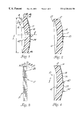
- FIG. 1 is a sectional view of one embodiment of the optical element of the present invention.
- FIG. 2 is a sectional view of one embodiment of the optical element of the present invention.
- FIG. 3 is a schematic view of the functional portion of the present invention.
- FIG. 4 is a sectional view of one embodiment of the optical element of the present invention.
- FIG. 5 is a schematic view of an injection molding machine with a mold for practicing the method of the present invention.
- FIG. 6 is a schematic view of an injection molding machine with a mold for practicing the method of the present invention, with the mold closed to form a mold cavity.
- An ophthalmic element comprises an injection molded, polymeric ophthalmic lens having a concave surface and a convex surface, and a laminate bonded to the injection molded, polymeric ophthalmic lens, the laminate comprising, in the following order: a) a first resinous layer, b) a functional layer selected from the group consisting of a light polarizing layer and a photochromic layer, and c) a second resinous layer, the first resinous layer being bonded to the convex surface of the injection molded, polymeric ophthalmic lens.
- the polymeric ophthalmic lens preferably comprises a polycarbonate resin.
- the first resin layer preferably is directly bonded to the polymeric ophthalmic lens.
- the first resinous layer may be adhesively bonded to the polymeric ophthalmic lens or may be fused to the polymeric ophthalmic lens.
- the functional layer preferably comprises a light polarizing layer or a photochromic layer.
- the ophthalmic element may be an injection molded, polymeric ophthalmic lens with no ophthalmic prescription power.
- the article 8 which may take the form of an optical element such as an optical lens 10 , includes a primary part, such as a power portion 12 and a secondary part, such as a functional portion 14 .
- the functional portion 14 and the power portion 12 are attached together.
- the functional portion 14 and the power portion 12 are preferably integrally connected to each other and, more preferably, are fused together.
- the functional portion 14 of the present invention provides a convenient and systematic way of combining a polarizing element with a polycarbonate lens, while retaining the ability to machine the polycarbonate lens to prescription specifications.
- the functional portion 14 may include a functional member 20 , such as a functional coating (not shown) or a functional film 21 , that is attached to a first sheet 22 .
- the functional portion 14 may include a second sheet 24 such that the functional member 20 is sandwiched between the first sheet 22 and the second sheet 24 .
- the functional member 20 may be structured in a variety of ways, such as in composite or multi-layer fashion, in addition to the functional film 21 .
- the functional member 20 could be structured to include film portions (not shown) that entrap and protect an operative substance, such as inorganic photochromic crystals.
- the functional member 20 could include multiple functional film portions (not shown) that are laminated together using a conventional technique.
- a functional element such as a polarizing element (not shown), may be incorporated into the functional member 20 , such as the functional film 21 .
- the functional portion 14 that includes the polarizing element may then be included in a mold, such as an injection mold, so that the film 21 with the polarizing element is integrally molded as part of the lens 10 .
- a different functional element such as a photochromic, abrasion resistant, or tinting element, may be incorporated into the functional member 20 , such as the film 21 , and integrally molded as part of the lens 10 .
- the functional elements may be made by many convenient manufacturing processes, including but not limited to lamination of the layers, adhesive securement of the individual layers, and extrusion of one or more layers (or all three layers) to form the three layer element (referred to as a laminate, but available for manufacture, as noted above, by processes in addition to lamination).
- a preferred method of making the functional element is to extrude layers in sequence or at the same time in the appropriate order of layers.
- the center layer of the three layers should be the layer with the functional capability so that a layer furthest from the ophthalmic element acts as a scratch resistant or protective layer, and the layer closest to the ophthalmic element acts as a cushion or tying layer to the ophthalmic element. It is structurally possible to use a two layer laminate (with the topmost protective resin layer and the ophthalmic element) by using a dry film adhesive or liquid adhesive between the ophthalmic element and the functional layer, but this is a much less preferred method of manufacture.
- the functional portion 14 may incorporate one or more functional properties. Essentially, the functional portion 14 operates to put incorporated functional properties in working relation with the power portion 12 .
- Some functional properties of interest include filtering features, such as light polarization and photochromism. Additional examples of functional properties of interest include cosmetic properties, such as lens decor, indicia, tint and color. Still further examples of functional properties include durability features, such as hardness, abrasion resistance, and chemical resistance.
- the functional portion 14 includes a light polarizing component or a photochromic component that functions as a filtering portion of the lens 10 . Alternatively, or in addition, portions of the functional portion 14 may be tinted to function as a cosmetic portion of the lens 10 .
- the power portion 12 of the lens 10 maybe contoured during initial formation to have an optical magnification characteristic that modifies the focal power of the lens 10 .
- the power portion 12 may be machined after initial formation to modify the focal power of the lens 10 .
- the power portion 12 provides a substantial amount of the optical power and magnification characteristics to the lens 10 .
- the functional portion 14 inherently affects the optical power and magnification characteristics of the lens 10 since the functional portion 14 contributes to the overall thickness of the lens 10 .
- the power portion 12 provides the majority of the lens 10 optical power and magnification characteristics. Apportioning the majority of optical power and magnification to the power portion 12 permits selection of power portion 12 material and power portion 12 formation techniques that are optimum for superior lens 10 optical power and magnification characteristics, without adversely affecting selection of optimum functional portion 14 materials and formation techniques.
- the power portion 12 of the lens 10 has both a rear surface 16 and a front surface 18 .
- the functional portion 14 of the lens 10 may be coextensive with the front surface 18 of the power portion 12 , as in FIG. 1 .
- the functional portion 14 may overlap only a portion of the front surface 18 of the power portion 12 , as in FIG. 2 .
- FIGS. 1, 2 , and 4 indicate definite lines of demarcation between the power portion 12 and the functional portion 14 , such definite lines do not necessarily exist when the power portion 12 and the functional portion 14 are integrally connected. Rather, because of intermolecular bonding, the demarcation line between the power portion 12 and the functional portion 14 maybe somewhat blurred when the power portion 12 and the functional portion 14 are integrally connected.
- the functional portion 14 may take the form of a plate 17 , as in FIG. 3, that is separated from a functional laminate 19 .
- the functional laminate 19 includes the functional member 20 , such as the functional film 21 .
- the functional film 21 may include a base film (not shown) and a functional medium (not shown) that is incorporated into or onto the base film.
- the functional member 20 may include more than one base film (not shown).
- the functional film 21 may include the functional medium (not shown) and a base resin (not shown), with the functional medium and the base resin being homogeneously blended together prior to formation of functional film 21 from the medium/resin mixture.
- the functional laminate 19 includes the first sheet 22 and, optionally, includes the second sheet 24 . If the second sheet 24 is included, the first and second sheets 22 , 24 are located on opposing sides of the functional member 20 .
- the first sheet 22 may be attached to the functional member 20 , such as the functional film 21 , by first adhesive 26 , and the second sheet 24 , if included, may be attached to the functional member 20 by second adhesive 28 .
- the first adhesive is typically not included when the functional member 20 is the functional coating (not shown).
- a first coating 30 may optionally be applied onto the first sheet 22 and a second coating 32 may optionally be applied onto the second sheet 24 , if the second sheet 24 is included.
- the second sheet 24 and the first and second coatings 30 and 32 are depicted with dashed lines to illustrate the optional nature of the second sheet 24 and the coatings 30 , 32 .
- the functional portion 14 may consist of a functional wafer (not shown) that includes the first sheet 22 .
- the functional member 20 and thus the functional film 21 , may consist of either the second sheet 24 , the second coating 32 , or the second sheet 24 that is coated with the second coating 32 .
- the functional wafer may optionally also include either the first adhesive 26 or the second adhesive 28 to attach the second sheet 24 to the first sheet 22 .
- the first sheet 22 may optionally include the first coating 30 .
- the functional portion 14 may be attached to the power portion 12 with either the first sheet 22 , the second sheet 24 , the first coating 30 , or the second coating 32 in contact with the power portion 12 .
- the functional portion 14 is attached to the power portion 12 with either the first sheet 22 or the second sheet 24 in contact (not shown) with the power portion 12 , since the first and second coatings 30 , 32 tend to degrade adhesion of the functional portion 14 to the power portion 12 .
- the second sheet 24 When the first sheet 22 or the first coating 30 is in contact with the power portion 12 , the second sheet 24 , if included, may form an outside surface 34 of the lens 10 that is open to atmosphere and that protects the functional member 20 from marring and abrasion.
- the second coating 32 if included, may substitute for the second sheet 24 as the outside surface 34 .
- the second sheet 24 when the second sheet 24 or the second coating 32 is in contact with the power portion 12 , the second sheet 24 , if included, may form the outside surface 34 of the lens 10 that is open to atmosphere and that protects the functional member 20 from marring and abrasion.
- the first coating 30 if included, may substitute for the first sheet 22 as the outside surface 34 .
- the functional portion 14 takes the form of the functional wafer (not shown)
- the second sheet 24 or the second coating 32 may form the protective outside surface 34 .
- the lens 10 may alternatively be characterized as having a front section (not shown), a functional section (not shown), and a rear section (not shown). In this characterization, the front section and the rear section are located on opposite sides of the functional section. Additionally, the functional member 20 may serve as the functional section and the power portion 12 may serve as the rear section. Additionally, either the first sheet 22 or the second sheet 24 , if included, may serve as the front section.
- the functional member 20 preferably includes either the light polarizing property or the photochromic property.
- the base film or resin is preferably of the polyvinyl alcohol-type, as described in U.S. Pat. No. 5,051,309 to Kawaki, which is hereby incorporated by reference.
- suitable resins of either the base film or the base resin include polyvinyl alcohol, polyvinyl formal, polyvinyl acetal, and saponified (ethylene/vinyl acetate) copolymer film, with polyvinyl alcohol being especially preferred.
- the base film or base resin may include homo and copolymers of various materials, such as cellulose acetate butyrate, poly(n-butyl methacrylate), poly(isobutyl methacrylate), poly(methyl methacrylate), poly(ethyl methacrylate), polyethylene, polypropylene, poly(acrylonitrile), poly(vinyl acetate), poly(vinyl chloride), poly(butadiene), and polyamide, that are formed from appropriate monomers and pre-polymers using conventional polymerization technology.
- Cellulose acetate butyrate is the preferred material for the base film or base resin since cellulose acetate butyrate readily incorporates photochromic dyes and since photochromic dyes activate and perform well in cellulose acetate butyrate.
- suitable dichroic substances such as dichroic dyes, for imparting the light polarizing property to the base film or resin are listed in U.S. Pat. No. 5,051,309 to Kawaki et al.
- suitable dichroic substances include Chlorantine Fast Red (C.I. 28160), Chrysophenine (C.I. 24895), Sirius Yellow (C.I. 29000), Benzopurpurine (C.I. 23500), Direct Fast Red (C.I. 23630), Brilliant Blue 6B (C.I. 24410), Chlorazol Black BH (C.I. 22590), Direct Blue 2B (C.I. 22610), Direct Sky Blue (C.I. 24400), Diamine Green (C.I.
- the dichroic substance incorporated in the base film or resin may be either a single dichroic substance or a mixture that includes two or more of the dichroic substances.
- the functional member 20 may incorporate any organic or inorganic photochromic substance or compound, such as photochromic substances or compounds that are compatible with the base film or resin and that are capable of imparting photochromic properties to the base film or resin.
- the photochromic substances or compounds incorporated in the functional member 20 may be a mixture that includes two or more different dichroic substances or compounds.
- organic photochromic compounds suitable for imparting photochromic properties to the functional member 20 such as the base film or resin, include naphthopyrans, spironaphthopyrans, fulgides, fulgimides, salicylates, triazoles, oxazoles, and azobenzenes.
- Silver halide is one example of an inorganic photochromic compound that is suitable for imparting photochromic properties to the functional member 20 , such as the base film or resin.
- the functional portion 14 substantially prevents the structure of the dichroic substance(s) or the photochromic compound(s) from being altered due to placement of the dichroic substance(s) or the photochromic compound(s) in working relation with the power portion 12 .
- the functional portion 14 prevents alteration of the structure of dichroic substance(s) and photochromic compound(s) due to placement of the dichroic substance(s) or the photochromic compound(s) in working relation with the power portion 12 .
- the functional portion 14 substantially prevents the light polarizing activity of the dichroic substance(s) and the photochromic activity of the photochromic compound(s) from being altered due to placement of the dichroic substance(s) or the photochromic compound(s) in working relation with the power portion 12 .
- the functional portion 14 prevents alteration of the light polarizing activity of the dichroic substance(s) and prevents any significant alteration of the photochromic activity of the photochromic compound(s) due to placement of the dichroic substance(s) or the photochromic compound(s) in working relation with the power portion 12 .
- naphthopyran compounds suitable for imparting photochromic properties to the functional member 20 include novel naphthopyran compounds that may be represented by graphic formula I as follows:
- graphical formula I includes all structural isomers of the compounds represented by graphical formula I.
- substituents may be placed on the pyran portion and the naphtho portion of the naphthopyran rings.
- the positions represented in graphic formula I by R 4 , R 5 , R 6 , R 7 , R 8 , R 9 , R 10 , and R 11 , respectively, may be filled with hydrogen; a stable organic radical, such as alkyl, alkoxy, unsubstituted or substituted phenyl, naphthyl, cycloalkyl, furyl, alkoyl, alkoyloxy, aroyl, aroyloxy; a heterocyclic group; halogen; a nitrogen-substituted group, such as amino or nitro; or a nitrogen-substituted ring compound, such as morpholino, piperidino, or piperazino.
- A is hydrogen, a substituted phenyl group, or a substituted naphthyl group
- B is hydrogen, a substituted phenyl group, or a substituted naphthyl group, provided that at least one of A and B is substituted phenyl or substituted naphthyl.
- any phenyl or naphthyl group or groups at A or B are selected from the following: a stable organic radical, such as alkyl, alkoxy, unsubstituted or substituted phenyl, naphthyl, cycloalkyl, furyl, alkoyl, alkoyloxy, aroyl, aroyloxy; a heterocyclic group; halogen; a nitrogen-substituted group, such as amino or nitro; and a nitrogen-substituted ring compound, such as morpholino, piperidino, or piperazino; provided that at least one substituent of at least one substituted phenyl or substituted naphthyl at either A or B is phenyl, naphthyl or furyl.
- a stable organic radical such as alkyl, alkoxy, unsubstituted or substituted phenyl, naphthyl, cycloalkyl, furyl, alkoyl, al
- Preferred naphthopyran compounds for imparting photochromic properties to the functional member 20 include 3-(4-biphenylyl)-3-phenyl-8-methoxy-3H-naphtho[2,1b]pyran, 3-(4-biphenylyl)-3-phenyl-3H-naphtho[2,1b]pyran, and 3,3-di(4-biphenylyl)-8-methoxy-3H-naphtho-[2,1b]pyran.
- spironaphthopyran compounds suitable for imparting photochromic properties to the functional member 20 include novel spironaphthopyran compounds that may be represented by graphic formula II as follows:
- graphical formula II includes all structural isomers of the compounds represented by graphical formula II.
- R 1 , R 2 , R 5 , R 6 , R 7 , R 8 , R 9 , and R 10 may be filled with hydrogen; a stable organic radical, such as alkyl, alkoxy, phenyl, naphthyl, cycloalkyl, furyl, alkoyl, alkoyloxy, aroyl, aroyloxy; a heterocyclic group; a halogen; a nitrogen-substituted group, such as amino or nitro; or a nitrogen-substituted ring compound, such as morpholino, piperidino, or piperazino.
- the position represented by A is filled by a substituted divalent aromatic radical.
- the substituents of the divalent aromatic radical may be hydrogen or a stable organic radical such as alkyl, alkoxy, phenyl, naphthyl, cycloalkyl, furyl, alkoyl, alkoyloxy, aroyl, or aroyloxy. Additionally, the substituents of the substituted divalent may also be substituted with alkyl, alkoxy, phenyl, naphthyl, cycloalkyl, furyl, alkoyl, alkoyloxy, aroyl, or aroyloxy.
- Preferred spironaphthopyran compounds for imparting photochromic properties to the functional member 20 include 8-methoxyspiro(3H-naphtho[2,1-b]pyran-3,9′-fluorene), spiro(3H-naphtho[2,1-b]pyran-3,9′-fluorene), 8-methoxyspiro(3H-naphtho[2,1-b]pyran-3,1′-tetralone), 6′,7′-dimethoxy-8-methoxyspiro(3H-naphtho[2,1-b]pyran-3,1′-tetralone), 7′-methoxy-8-methoxyspiro(3H-naphtho[2,1-b]pyran-3,1′-tetralone), 2′,3′-diphenyl-8-methoxyspiro(3H-naphtho[2,1-b]pyr
- the first sheet 22 and the second sheet 24 should be compatible with the power portion 12 , the functional member 20 , the first and second adhesives 26 , 28 , and, if included, the first and second coatings 30 , 32 .
- compatibility means that the first sheet 22 or the second sheet 24 , as appropriate, is capable of either strongly adhering to or strongly fusing with the material of the power portion 12 .
- compatibility means that the material of the first sheet 22 and of the second sheet 24 is incapable of undesirably reacting with other lens 10 components to degrade the power portion 12 , the functional member 20 , the first adhesive 22 , the second adhesive 24 , the first coating 30 (if included), the second coating 32 (if included), or functional media, such as photochromic or polarizing compounds incorporated in the functional member 20 .
- the power portion 12 and the one of the first sheet 22 and the second sheet 24 that is attached to the power portion 12 may generally be made of any resinous material.
- the first sheet 22 and the second sheet 24 may each be made of different materials, such as different thermoplastic resins.
- either or both of the sheets 22 , 24 may be made of a different material than the power portion 12 is made of.
- the power portion 12 and the one of the first sheet 22 and the second sheet 24 that is attached to the power portion 12 are each made of any of a variety thermoplastic resins, including homopolymers and copolymers of polycarbonate, amorphous polyolefin, polystyrene, and acrylic compounds, so long as the aforementioned material compatibility requirement is met, to permit fusion of the power portion 12 to the first sheet 22 or second sheet 24 . More preferably, the power portion 12 and the one of the first sheet 22 and the second sheet 24 that is attached to the power portion 12 are each made of the same thermoplastic resin to further enhance fusion of the power portion 12 to the first sheet 22 or second sheet 24 .
- first adhesive 26 and the second adhesive 28 Materials suitable for use as the first adhesive 26 and the second adhesive 28 must have good optical properties, including high optical transparencies, no yellowing upon exposure to sunlight, an ability to flex during injection molding without becoming crazed, minimal shrinkage during curing, and must meet the aforementioned material compatibility requirement.
- suitable materials for the first adhesive 26 and the second adhesive 28 include acrylic-type, epoxy-type and urethane-type adhesives, such as Loctite® FMD-207, Loctite® FMD-338, Loctite® FMD-436, and Loctite® 3311, each available from Loctite Corporation of Hartford, Conn.; Norland Optical Adhesive Type 68 available from Norland Products. Inc. of New Brunswick, N.J.; and Summers Laboratories Type SK-9 available from Summers Laboratories, Inc. of Collegeville, Pa.
- the materials used for the first adhesive 26 and the second adhesive 28 may be curable by thermal treatment or by treatment with ultraviolet light.
- the first coating 30 and the second coating 32 may be formed of any material(s) suitable for providing hardness, abrasion resistance, and/or chemical resistance to the functional portion 14 , so long as the aforementioned material compatibility requirement is met.
- suitable coating materials include hard acrylic coatings and hard polysiloxane compounds.
- the one of the sheets 22 , 24 that is in contact with the power portion 12 does not include the respective coating 30 , 32 , since it has been found that coating of the one of the sheets 22 , 24 that is in contact with the power portion 12 tends to decrease bonding of the functional portion 14 to the power portion 12 .
- a center thickness B of the power portion 12 preferably ranges from about 0.9 mm to about 20.0 mm and more preferably ranges from about 1.0 mm to about 9.0 mm.
- a center thickness C of the functional portion 14 may be any thickness that is adequate to obtain the desired functional effect, such as the light polarizing effect or the photochromic effect, in the lens 10
- the center thickness C of the functional portion 14 preferably ranges from about 0.2 mm to about 2 mm and more preferably ranges from about 0.3 mm to about 0.7 mm.
- the center thicknesses B and C of the power portion 12 and the functional portion 14 are depicted in FIG. 1 as being offset from the axis Z of the lens, it is to be understood that the center thicknesses B and C of the power portion 12 and the functional portion 14 , respectively, are each measured along the axis Z.
- the center thickness A of the lens 10 preferably ranges from about 1.5 mm to about 22.0 mm and more preferably ranges from about 1.6 mm to about 10.0 mm.
- the functional film 21 may consist of either the second sheet 24 , the second coating 32 , or the second sheet 24 that is coated with the second coating 32 .
- the functional portion 14 takes the form of the functional wafer (not shown)
- the lens 10 may be either a single vision lens, a progressive multi-focal lens, an aspheric lens, an aspheric multi-focal lens, or a stepped multi-focal lens.
- Single vision lenses which may take the form of the lens 10 , have essentially the same focal power at any point on the outside surface 34 of the lens 10 when objects (not shown) located in front of the functional portion 14 of the lens 10 are viewed through the lens 10 from a select point X located behind the lens 10 and on the axis Z.
- the outside surface 34 should be substantially smooth, and is preferably very smooth, to help minimize generation of any irregular, unpredictable optical effects in the lens 10 .
- the focal power of the lens 10 changes in continuous increments when objects located in front of the outside surface 34 are viewed from the select point X through different points of the outside surface 34 .
- the focal power of the lens 10 when viewing objects from point X, changes in continuous increments when moving about the outside surface 34 , in part due to the smooth continuous nature of the outside surface 34 of the lens 10 that is progressive multi-focal.
- the front surface 18 and the outside surface 34 are aspherically shaped. Additionally, when objects are viewed from point X through the lens 10 that is progressive multi-focal, lines are not seen when moving between points about the surface 34 that have different focal powers.
- the lens 10 is a stepped multi-focal lens, such as the lens 10 depicted in FIG. 4, the front surface 18 of the power portion 12 is discontinuous.
- the lens 10 of FIG. 4 is a stepped bi-focal lens in which the front surface 18 is divided into a main focal surface 36 and a secondary focal surface 38 .
- the main focal surface 36 and the secondary focal surface 38 cooperate to define a stepped surface 40 that disrupts smooth transition between the main focal surface 36 and the secondary focal surface 38 .
- the secondary focal surface 38 may be elevated, at least in part, relative to the main focal surface 36 .
- FIG. 4 may be elevated, at least in part, relative to the main focal surface 36 .
- the main focal surface 36 may be elevated, at least in part, relative to the secondary focal surface 38 .
- the front surface 18 may be divided into more than two discontinuous surfaces, rather than only the two discontinuous surfaces, namely the main focal surface 36 and the secondary focal surface 38 , as depicted in FIG. 4 .
- the lens 10 may be either progressive multi-focal, aspheric multi-focal, or stepped multi-focal.
- the costs of obtaining the progressive and the aspheric multi-focal lenses are somewhat comparable to the cost of obtaining the stepped multi-focal lenses.
- Manufacture of stepped multi-focal lenses requires somewhat less expensive and somewhat less complicated tooling than does manufacture of progressive multi-focal lenses or manufacture of aspheric multi-focal lenses.
- actual manufacturing costs for stepped multi-focal lenses are somewhat higher that are manufacturing costs for progressive or aspheric multi-focal lenses.
- the lens 10 is preferably progressive multi-focal, rather than stepped multi-focal, since shaping of the functional portion 14 to match the shape of the front surface 18 of the power portion 12 is easier for the progressive multi-focal lens than for the stepped multi-focal lens.
- progressive multi-focal lenses are generally perceived by consumers to be a more sophisticated and cosmetically appealing lens than stepped multi-focal lenses.
- the lens 10 is preferably progressive multi-focal, rather than aspheric multi-focal, since progressive multi-focal lenses are generally perceived by consumers to be a more sophisticated and cosmetically appealing lens than aspheric multi-focal lenses.
- the lens 10 may be either a finished lens or a semi-finished lens.
- the focal power or focal power range of the lens is set during manufacture of the lens 10 and no further processing of the lens 10 is required to set the focal power or focal power range.
- additional processing after initial manufacture of the lens 10 such as grinding of a rear surface 42 of the lens 10 , is needed to set the focal power or focal power range of the lens 10 .
- the rear surface 42 may include a coating (not shown) to enhance the hardness and abrasion resistance of the rear surface 42 of the lens.
- the coating need only be applied to the outside surface 34 of the lens 10 , since the coating on the rear surface 42 of the lens 10 may be damaged or removed during further processing of the semi-finished lens.
- the rear surface 42 may include the coating (not shown) to simplify or reduce the cost of manufacturing the semi-finished lens.
- the method of making the lens 10 generally involves three distinct steps. First, the functional member 20 , such as the functional coating (not shown) or the functional film 21 , is prepared. Next, the functional portion 14 is prepared. Finally, the lens 10 is made by attaching the functional portion 14 to the power portion 12 .
- the functional member 20 such as the functional coating (not shown) or the functional film 21 .
- any of the sheets 22 , 24 or the coatings 30 , 32 may impart durability characteristics, such as hardness, abrasion resistance, and chemical resistance, to the lens 10 and especially to the outside surface 34 of the lens.
- the dichroic compound(s) may be incorporated into the base film to make the functional film 21 with the polarizing property using any suitable procedure.
- the base film (not shown) may be immersed in an aqueous solution of dichroic substance at a temperature ranging from about 10° C. to about 50° C. to effect absorption of the dichroic substance on the base film.
- the base film is stretched in one direction to a dimension ranging about 21 ⁇ 2 times to about 8 times the unstretched dimension of the base film in a water solution with a temperature ranging from about 10° C. to about 80° C.
- the water solution should contain a dissolved additive, such as a metal ion or boric acid, to effect adsorption and orientation of the dichroic substance(s) onto the base film.
- the organic photochromic compound(s) may be incorporated into the base film to make the functional film 21 having the photochromic property using any suitable procedure.
- a suitable procedure useful for the preferred naphthopyrans and spironaphthopyrans the photochromic compound(s) are dissolved in a suitable solvent.
- suitable solvents include butyl acetate; hexane; cyclohexane; various alcohols, including ethanol and methanol; and various ketones; such as cyclohexanone and methyl ethyl ketone.
- a photochromic compound/resin/solvent mixture is made by adding the photochromic compound/solvent solution to the molten monomer or molten pre-polymer of the homopolymer or copolymer selected for the base film.
- a suitable ultraviolet stabilizing compound may be incorporated into the photochromic compound/resin/solvent mixture to help stabilize the photochromic compound(s) against activation fatigue.
- the photochromic compound(s) and the homopolymer or copolymer resin selected for the base film are first mixed together.
- the solvent is then added to the photochromic compound/resin mixture, and the photochromic compound/resin/solvent mixture is heated to melt and/or dissolve the photochromic compound(s) and resin in the solvent and homogeneously mix all components of the mixture.
- the mixture of photochromic compound(s), solvent, and monomer or pre-polymer, however created, may be formed into a film or sheet by a suitable extrusion or casting method.
- the mixture is cast on a flat surface using a conventional thermoset plastic casting technique.
- the functional film 21 having the photochromic property remains.
- the inorganic photochromic compound(s) may be incorporated into the functional member 20 , such as the functional film 21 , having the photochromic property using any suitable procedure.
- the inorganic photochromic compound(s) may be any suitable potentially photochromic glass that is treated and ground to make photochromic glass particles in accordance with U.S. Pat. No. 4,622,184 to Barnhart et. al, which is hereby incorporated by reference.
- the photochromic glass particles may be blended with the base resin, as specified in U.S. Pat. No. 4,622,184, and then may be formed into the functional film 21 a conventional method, such as a suitable extrusion or casting method.
- the inorganic photochromic compound(s), such as silver halide particles may be co-deposited along with a monomer on a substrate, such as the base film, in accordance with U.S. Pat. No. 4,596,673 to Beale, which is hereby incorporated by reference.
- the monomer polymerizes as a result of the co-deposition to secure the silver halide to the base film.
- Monomers that are suitable for use in practicing the method of U.S. Pat. No. 4,596,673 include hexamethyldisiloxane, hexamethyldisilizane, vinyl trimethylsiloxane, tetramethyldisiloxane, and vinyl trimethoxysilane.
- the functional film 21 that incorporates the inorganic photochromic compound(s), such as the silver halide particles, remains after the monomer polymerizes.
- the base resin may be prepared by combining (1) an unsaturated polyester resin produced by esterification of a polybasic unsaturated organic acid with a polyhydric alcohol and (2) a polar vinyl monomer of the type that forms polar solvent soluble plastic when homopolymerized, in accordance with U.S. Pat. No. 4,110,244 to Hovey, which is hereby incorporated by reference.
- One or more unsaturated vinyl monomers may, if desired, be blended with the unsaturated polyester resin before the polyester resin is combined with the polar vinyl monomer.
- the mixture of the unsaturated polyester resin, either with or without the unsaturated vinyl monomer(s), and the polar vinyl monomer may be polymerized and cast in accordance with U.S. Pat. No.
- the inorganic photochromic compound(s), such as silver halide crystals may be coated with an inorganic material to make coated photochromic material, in accordance with U.S. Pat. No. 4,046,586 to Uhlmann et al., which is hereby incorporated by reference.
- the coated photochromic material may then be blended, as indicated in the Uhlmann patent, with a solution of the base resin in a suitable solvent.
- the functional film 21 may then be prepared by casting the mixture of the base resin, the solvent, and the coated photochromic material, using a conventional casting technique.
- the inorganic photochromic compound(s), such as silver halide crystals may be incorporated into a photochromic plastic material, as explained in U.S. Pat. No. 4,049,567 to Chu et al., which is hereby incorporated by reference.
- the photochromic plastic material may then be sandwiched between two sheets of the base film and sealed with epoxy resin, in accordance with the Chu patent, to form the functional member 20 .
- the functional portion 14 may be made by laminating the first sheet 22 and, if desired, the second sheet 24 to the functional member 20 using the first adhesive 26 and the second adhesive 28 , respectively. Any conventional adhesive-based lamination technique, such as rolling to apply suitable pressure, may be relied upon to laminate the sheets 22 , 24 , to the functional member 20 .
- the coating 30 if included, may be applied to the first sheet 22 either before or after lamination of the sheet 22 to the functional member 20 .
- the coating 32 if included, may be applied to the second sheet 24 either before or after lamination of the sheet 24 to the functional member 20 .
- the functional portion 14 may be prepared by applying the functional coating onto the first sheet 22 using any suitable procedure, such as spraying, brushing, or powder application.
- suitable materials that are suitable for forming the functional coating include those materials that are suitable for providing functional properties, such as hardness, abrasion resistance, and/or chemical resistance, to the functional portion 14 , so long as the aforementioned material compatibility requirement is met.
- suitable materials for the functional coating include hard acrylic coatings and hard polysiloxane compounds.
- the first adhesive 26 is optional since the functional coating may be applied directly onto the first sheet 22 . typically provides the outside surface 34 of the lens 10 .
- the second adhesive 28 , the second sheet 24 , and the second coating 32 are optional when the functional member 20 is the functional coating since the functional coating may be used to form the outside surface 34 of the lens 10 .
- the functional coating may be selected to provide the outside surface 34 with desirable functional properties, such as hardness, abrasion resistance, and/or chemical resistance.
- the functional film 21 that incorporates the polarizing property is a purchased item known as POLA SHEET.
- POLA SHEET may be obtained by contacting Yushi Seihin Co. in Tokyo, Japan. It is believed that the functional film 21 having the photochromic property is not available as a purchased item. Therefore, it is necessary to make the functional film 21 having the photochromic property using the method of the present invention.
- the functional portion 14 when the functional portion 14 takes the form of the functional wafer (not shown), the functional portion 14 may be prepared by laminating the second sheet 24 to the first sheet 22 using the first adhesive 26 or the second adhesive 28 . Any conventional adhesive-based lamination technique may be relied upon to laminate the sheets 22 , 24 , together.
- the coatings 30 , 32 if included, may be applied to the first sheet 22 and the second sheet 24 , respectively, either before or after lamination of the sheets 22 , 24 .
- the second coating 32 may be applied to the first sheet 22 using any conventional coating application technique.
- the power portion 12 and the functional portion 14 may be combined to make the lens 10 using any conventional technique, such as laminate bonding, injection molding, compression molding, or injection-compression molding (sometimes called “coining”).
- any conventional technique such as laminate bonding, injection molding, compression molding, or injection-compression molding (sometimes called “coining”).
- the plate 17 must be separated from the functional laminate 19 and configured to the size and pattern the plate 17 will have when included in the lens 10 .
- the plate 17 may be separated from the laminate 19 using any conventional technique. Other than in the Examples, all subsequent comments about plate 17 apply with equal force to the functional wafer.
- Some examples of potential plate 17 sizes and shapes are depicted in FIGS. 1 and 2.
- the plate 17 may be pre-shaped either before being incorporated into the lens 10 or, alternatively, the plate 17 may be shaped while being incorporated into the lens 10 .
- the plate 17 may be pre-shaped using any suitable laminate shaping process.
- a suitable process entails heating the plate 17 to a suitable temperature. Simultaneous with or subsequent to the heating, positive pressure is applied to the plate 17 using a suitable device to shape the plate 17 and match the shape of the front surface. 18 of the power portion 12 . Once the plate 17 is appropriately shaped, the plate 17 is cooled to room temperature and the positive pressure is released.
- the power and functional portions 12 , 14 may be joined to make the lens 10 using a molding machine 100 , as in FIG. 5, that includes a plurality of mold surfaces 102 .
- a molding machine 100 that includes a plurality of mold surfaces 102 .
- the mold surfaces 102 define a plurality of mold cavities 104 .
- two mold cavities 104 are depicted in FIG. 6, it is to be understood that the molding machine 100 may include only one of the mold cavities 104 and may also include more than two of the cavities 104 .
- the molding machine 100 is preferably a reciprocating screw injection molding machine.
- the molding machine 100 includes an injection portion 106 and a clamping portion 108 .
- the injection portion 106 includes a barrel 110 that contains a reciprocating screw (not shown).
- the injection portion 106 also includes a hopper 112 that directs pelletized thermoplastic resin (not shown) to the screw.
- the injection portion 106 further includes a plurality of heater bands 114 arranged about the barrel 110 to melt the thermoplastic resin.
- the injection portion 106 includes a hydraulic power unit 116 that rotates and reciprocates the screw.
- the clamping portion 108 includes a mold portion 118 and a drive portion 120 that opens and closes the mold portion 118 .
- the mold portion 118 includes a fixed mold half 122 that is in fixed association with the injection portion 106 .
- the mold portion 118 also includes a movable mold half 124 that is in mateable association with the fixed mold half 122 .
- the mold halves 122 , 124 cooperatively define the mold cavities 104 .
- the mold surfaces 102 of each mold cavity 104 may be classified into three types of molding surfaces, namely, a convex surface 126 , a concave surface 128 , and radial surfaces 130 .
- the convex surface 126 of the mold cavity 104 defines the outside surface 34 of the lens 10 .
- the convex surface 126 may be configured to match any shape of the outside surface 34 of the lens 10 , including the discontinuous shape, as in FIG. 4, of the outside surface 34 .
- the concave surface 128 of the mold cavity 104 defines the rear surface 42 of the lens 10 .
- the radial surfaces 130 of the mold cavity 104 define a perimeter 44 of the lens 10 .
- the radial surfaces 130 may be entirely defined in the movable mold half 124 , as depicted in FIG. 5 .
- the radial surfaces 130 may be entirely defined in the fixed mold half 122 or may be partially defined in the fixed mold half 122 and partially defined in the movable mold half 124 .
- the fixed mold half 122 has a sprue 132 that is in fluid communication with the injection unit 106 . Additionally, opposing surfaces 134 of the fixed mold half 122 and the movable mold half 124 cooperatively define branches 136 , as depict in FIG. 6, which place the injection unit 106 and the sprue 132 in fluid communication with each mold cavity 104 .
- the mold portion 118 additionally includes a plurality of cooling lines 138 oriented within the mold halves 122 , 124 to cool molten thermoplastic resin after injection of the resin into the mold cavity 104 is complete.
- the movable mold half 124 preferably includes a fixed mold plate 146 and a movable mold plate 148 .
- the mold half 124 also includes a plurality of sleeves 150 that are in substantial registry with radial surfaces 130 of the mold cavities 104 .
- the mold half 124 further includes a plurality of pistons 152 that are slideably received within the sleeves 150 and are fixedly attached to the mold plate 148 at ends 154 . Ends 156 of the pistons 152 form the convex surfaces 126 of the mold cavities 104 .
- the drive portion 120 of the clamping unit 108 includes a hydraulic ram 158 that is in working relationship with the movable mold half 124 .
- the drive portion 120 further includes a hydraulic power unit 160 that drives the hydraulic ram 158 and places the movable mold portion 124 either in an open condition 162 , as in FIG. 5, or in a closed position 164 , as in FIG. 6 .
- the movable plate 148 and thus the pistons 152 , are in working relations with the hydraulic ram 158 . Movement of the plate 148 and the pistons 152 is timed so that the pistons 152 move in the direction of arrow D, as best depicted in FIG. 5, after molding of the lenses 10 is complete and as the mold halves 122 , 124 are separated. Movement of the pistons 152 in direction D ejects the lenses 10 from the mold cavities 104 by substantially even application of pressure over the rear surface 42 of each lens 10 . Conversely, movement of the plate 148 and the pistons 152 is timed so that the pistons 152 move in the direction of arrow E to orient the surfaces 126 , 128 , 130 for molding following ejection of the lenses 10 .
- the clamping unit 108 includes a plurality of tie bars 166 that help maintain the movable mold half 124 in mateable alignment with the fixed mold half 122 .
- the fixed mold half 122 includes cylindrical female guides 168
- the movable mold half 124 includes cylindrical male members 170 that slidably engage respective cylindrical female guides 168 .
- the guides 168 and members 170 help maintain proper alignment of the fixed and movable mold halves 122 , 124 relative to each other.
- the mold halves 122 , 124 are made of a low carbon plastic mold steel, such as Series P20 stainless steel tool steel.
- the molding machine 100 may be any suitable injection molding machine, such as a Vista injection molding machine which is available from Cincinnati Milacron of Batavia, Ohio.
- the plate 17 that makes up the functional portion 14 is placed against a recess 172 of the mold plate 146 , as best depicted in FIG. 5, before the mold halves 122 , 124 are closed.
- the recess 172 may be defined by a notch (not shown) in the convex surface proximate the intersection of the convex surface 126 and the radial surface 130 , as best depicted in FIG. 6 .
- the recess 172 may be defined by the intersection of the convex surface 126 and the radial surface 130 .
- the convex surface 126 may be notched (not shown) accordingly to reposition the recess 172 elsewhere in the convex surface 126 to accommodate the different size or shape of the front surface 18 .
- the plate 17 may be pre-shaped to match the shape of the front surface 18 of the power portion 12 .
- the molding machine 100 may be configured with a vacuum source 174 and associated vacuum lines that are in communication with the convex surface 126 of each cavity 104 , as in FIG. 5 .
- each plate 17 may be placed against respective recesses 172 and pulled into communication with respective convex surfaces 126 without pre-shaping the plates 17 prior to placement in the machine 100 .
- each plate 17 should be placed in the respective mold cavity 104 so that a pneumatic seal (not shown), a mechanical seal (not shown), or a combination pneumatic/mechanical seal (not shown) is created between each plate 17 and the respective convex surface 126 of the mold half 122 .
- the mechanical seal relates to the plates 17 that are pre-shaped. To obtain the mechanical seal, the plates 17 must be properly sized to take into account expansion of the metal used to make the mold halves 122 , 124 so that the plates 17 remain snug and secure within the recesses 172 when molten resin is injected into the mold cavities 104 .
- the pneumatic seal relates to the plates 17 that are shaped by the vacuum source 174 and may also relate to the plates 17 that are pre-shaped.
- the pneumatic seal may be created by applying sufficient vacuum to maintain the plates 17 snugly in registry against the respective convex surfaces 126 while molten resin is injected into the mold cavities 104 .
- Sealing between plates 17 and respective convex surfaces 126 is necessary to prevent molten thermoplastic resin that is injected into the mold cavities 104 from flowing between the plates 17 and respective convex surfaces 126 .
- Intrusion of the molten resin between the plates 17 and the convex surfaces 126 would be expected to undesirably create one or more optical or cosmetic problems, such as delamination of the functional film from the sheet 22 , 24 , burning of the plate 17 or the film 21 , stress points within the plate 17 , warpage of the plate 17 , and flow lines on the outside surface 34 of the lens 10 .
- the molding machine 100 is closed to form the mold cavities 104 , as in FIG. 6 .
- the thermoplastic resin selected for the power portion 12 is then injected into the cavities 104 in the molten state to fill that portion (not shown) of the cavities 104 not occupied by the plates 17 and form the power portion 12 of each lens 10 . Additionally, in each cavity 104 , the injected resin comes into abutting contact with the plate 17 located in the cavity 104 .
- the temperature of the injected resin causes the power portion 12 formed by the injected resin to fuse with the functional portion 14 at the one of the sheets 22 , 24 that is preferably oriented against the front surface 18 of the power portion 12 .
- each cavity 104 The heat present in each cavity 104 is preferably sufficient to cause the power portion 12 and the functional portion 14 to fuse together by welding into a permanent bond.
- the cavity 104 may be opened by moving the molding halves 122 , 124 away from each other, as in FIG. 5 .
- the lens 10 is then ejected from the molding machine 100 by movement of the appropriate piston 152 in direction D.
- Formation of the power portion 12 in the molding machine 100 highlights another important advantage of the present invention, namely, the equalizing effect that the power portion 12 exerts within the lens 10 upon any non-uniformities in the thickness of the functional portion 14 .
- the functional portion 14 be substantially uniform in thickness, some variation in thickness of the functional portion 14 is permissible. Thickness variation in the functional portion 14 is permissible because mold cavity 104 is uniform in thickness. Thus, injection of resin into the mold cavity 104 compensates for any non-uniformities in thickness of the functional portion 14 by varying the thickness of the power portion 12 accordingly.
- each lens 10 may be coated with a suitable coating, such as an acrylic or a polysiloxane coating composition, to provide a hard surface on the lens 10 .
- a suitable coating such as an acrylic or a polysiloxane coating composition
- Coating may be accomplished using conventional techniques such as dipping, spraying, or spin-coating.
- the coating may be applied to the outside surface 34 and the rear surface 42 of the lens 10 .
- the coating need only be applied to the outside surface 34 of the lens 10 , since the coating on the rear surface 42 may be damaged or removed during further processing of the semi-finished lens.
- the coating may be applied to all surfaces of the semi-finished lens, including the outside surface 34 and the rear surface 42 to simplify or reduce the cost of manufacturing the semi-finished lens.
- a number of advantages are realized when the method of the present invention is used to make the lens 10 .
- functional properties are readily incorporated into the lens 10 without altering the substantially smooth nature, and preferably the very smooth nature, of the outside surface 34 .
- undesirable and unpredictable optical effects that would otherwise be expected to occur in the lens 10 if the outside surface 34 were other than smooth in nature, are greatly minimized or eliminated altogether when the lens 10 of the present invention is used.
- the lens 10 may be finished, as opposed to semi-finished, with the power portion 12 being contoured to modify the focal power of the lens 10 .
- the lens 10 may be semi-finished so that the power portion is capable of being machined, at some time following manufacture, to modify the focal power of the lens 10 .
- the functional portion 14 substantially beneficially prevents the structural alteration of dichroic substances and photochromic compounds due to placement of the dichroic substances or the photochromic compounds in working relation with the power portion 12 . Furthermore, it has been discovered that the functional portion 14 substantially prevents the alteration of the light polarizing activity of dichroic substances and alteration of the photochromic activity of photochromic compounds due to placement of the dichroic substances and the photochromic compounds, respectively, in working relation with the power portion 12 .
- the method of the present invention provides a systematic approach for incorporating a wide variety of functional properties into the lens 10 simply by modifying the functional portion 14 . Also, the method of the present invention provides a systematic method for incorporating functional properties into optical elements, such as the lens 10 , even as new materials supplant presently favored materials, such as polycarbonate, in lens 10 manufacture. When a new material is developed, the material used to make the first sheet 22 and the second sheet 24 may be modified to maintain compatibility between the new material and the materials used in the functional portion 14 , including the materials of the first and second sheets 22 , 24 .
- the functional portion 14 may be attached to any surface of a new or existing lens (not shown) using any conventional technique, such as adhesive attachment or laminate bonding.
- functional properties may be imparted to new lenses that initially lack the properties.
- functional properties may be imparted to existing lenses, instead of discarding the existing lenses and manufacturing new lenses that include the functional properties.
- suitable solvents may be applied to remove the functional portion 14 from the existing lens (not shown) so that a different one of the functional portions may be applied to the existing lens. This option facilitates changing the functional properties of the existing lens when the need for particular functional properties changes.
- Examples 1-4 demonstrates formation of the lens 10 with the polarizing property incorporated in the functional portion 14 . Additionally, the lens 10 formed in Examples 1-4 each have different physical dimensions and different focal powers.
- the functional laminate 19 included the functional film 21 , the first and second sheets 22 , 24 , and the first and second adhesives 26 , 28 .
- the functional laminate 19 also included the second coating 32 , but did not include the first coating 30 .
- the functional laminate 19 included the light polarizing property and consisted of POLA SHEET obtained from Mitsubishi Engineering Plastics Co.
- the base film of the functional film 21 was made of polyvinyl alcohol, and the first and second sheets 22 , 24 were made of polycarbonate.
- the film 21 was about 0.003 mm thick and the first and second sheets 22 , 24 were each about 0.3 mm thick.
- the adhesives 26 , 28 which were each about 0.003 mm thick, were ordinary acrylic-type, epoxy-type, or urethane-type adhesives.
- the coating 32 which was about 0.003 mm thick, was a hard polysiloxane coating.
- the plate 17 was cut from the functional laminate to make the functional portion 14 .
- the plate 17 was generally round in shape and had substantially the same dimensions as the surface 18 of the power portion 12 to be made.
- the plate 17 which was not pre-shaped, was placed within the recesses 172 so that the second sheet 24 faced the convex surface 126 .
- the plate 17 was observed to have a snug fit within the recesses 172 that was suitable for creating the mechanical seal.
- the vacuum source 174 was activated to 28.5 millimeters of mercury to effect the pneumatic seal and to pull the plate 17 into registry with the convex surface 126 .
- the mold halves 122 , 124 were then closed to make the mold cavity 104 using the molding machine 100 .
- the clamping force of the machine 100 used in these examples was 160 tons, and the resin injection velocity was 1.5 inches per second.
- the resin melt temperature of the machine 100 was 585° F., and the mold temperature was 265° F.
- Molten Lexan® polycarbonate resin was injected into the cavity 104 .
- Lexan® polycarbonate is available from General Electric Plastics Co. of Pittsfield, Mass.
- the mold halves 122 , 124 were opened and the lens 10 was ejected from the mold half 122 .
- the lenses 10 of Examples 1-4 it was noted that no injected polycarbonate flowed between the plate 17 and the convex surface 126 . Additionally, no delamination of the functional portion 14 and no warping of the functional film 21 was observed. Furthermore, the functional portion 14 and the power portion 12 were found to be firmly attached to each other. No voids or inclusions were found anywhere in the power portion 12 , including proximate the functional portion 14 . After the inspection, the second sheet 24 of each lens 10 of Examples 1-4 was coated with the coating 32 using a conventional dip-coating technique.
- the lenses 10 produced in Examples 1-4 had diameters F and center thicknesses A as indicated in Table 2 below. Additionally, the design and resultant true curves of the lenses 10 were determined to have the values listed in Table 2 using conventional optical measurement techniques.
- the resultant true curve of each lens 10 is the optical curve of the lens 10 that is measured between opposite sides 46 of the lens 10 along the outside surface 34 , as in FIG. 1 .
- the design curve is the tooled curve of the lens 10 , namely the measured curve of the convex surface 126 of the mold cavity 104 , referring to FIG. 6 .
- Table 2 illustrates that incorporation of the functional portion 14 into the lens 10 in accordance with the present invention causes only essentially no variation between the resultant true curve and the design curve for each of the lenses 10 produced in Examples 1-4.
- the lenses 10 made in Examples 1-4 were ground to different finished prescription focal powers and were then found to have good combined power in the spherical and cylindrical axes. Also, the optical properties of the lenses 10 , including the optical clarity, optical wave, and optical power, were examined using a conventional lensometer apparatus and were found to be excellent.
- the functional portions 14 of each of the lenses 10 were also determined to be well adhered to the respective power portions 12 . Also, the functional portions 14 of each of the lenses 10 were tested for delamination and it was observed that the sheets 22 , 24 did not delaminate from the functional film 21 . Additionally, the outside surface 34 of each lens 10 was tested for abrasion using the test detailed in ASTM D 3359-78 and found to exhibit superior abrasion resistance.
- This example demonstrates formation of the functional film 21 from polymeric resin and photochromic dye.
- the polymeric resin was cellulose acetate butyrate
- the photochromic dye was 3-(4-biphenylyl)-3-phenyl-8-methoxy-3H-naphtho[2,1b]pyran.
- the first step is to blend the resin and the photochromic dye.
- 0.2 grams of the photochromic dye were mixed with 19.8 grams of pelletized cellulose acetate butyrate in a clean, dry, 250 ml glass Erlenmeyer flask.
- the pelletized cellulose acetate butyrate was Tenite grade 264-E2R300-01, which is available from Eastman Chemical Co. of Kingsport, Tenn.
- 110.5 grams of n-butyl acetate solvent were added to the dye/resin mixture.
- the Erlenmeyer flask was then placed in a heating container that held a suitable heat transfer fluid, e.g. ethylene glycol or diethylene glycol.
- the heat transfer fluid was heated to gradually warm the dye/resin/solvent mixture to 105° C.
- the dye/resin/solvent mixture was held at 105° C. and stirred, for about four hours, until the dye and resin dissolved in the solvent and the dye/resin/solvent mixture became homogeneously mixed.
- the resultant dye solution was then cooled to room temperature.
- a 24′′ ⁇ 30′′ ⁇ 0.375′′ piece of float glass was prepared for casting the film 21 by first leveling the glass and then cleaning the glass with acetone. Next, a mold release agent was prepared by dissolving one drop of n-octyl-trichloro-silane into 10 ml of xylene. The mold release agent was rubbed on the glass using a clean, folded paper tissue that had been dipped in the mold release agent.
- the functional film 21 was gently removed from the glass by first peeling an edge of the film 21 off the glass with the help of a razor blade.
- the film 21 after evaporation of the solvent, was determined to be about 0.0013 mm thick.
- the film 21 was placed in a spectrometer and the total light transmission without activation of the photochromic dye was determined to be about 92% over the range of the visible spectrum.
- the total light transmission was determined to be about 10% at 480 nm when the photochromic dye was activated using light provided by a 2.25 mw/cm 2 ultraviolet lamp.
- the maximum activation wavelength for the photochromic dye, (3-(4-biphenylyl)-3-phenyl-8-methoxy-3H-naphtho[2,1b] pyran) was 480 nm.
- the ultraviolet lamp was a Bondwand lamp available from Edmund Scientific, Inc. of Barrington, N.J.
- This example demonstrates formation of the functional laminate 19 using the functional film 21 produced in Example 5.
- two sheets of 3.5′′ ⁇ 3.5′′ ⁇ 0.010′′ Makrofol® PCEE polycarbonate (color: “nat”; finish: “EE”) was obtained from Bayer, Inc. (formerly Miles, Inc.) of Pittsburgh, Pa.
- the two polycarbonate sheets, which served as the first sheet 22 and the second sheet 24 each included protective layers on both sides of each sheet 22 , 24 .
- the polycarbonate sheet that was to be the first sheet 22 was placed on a hard, flat surface and the protective layer on the side of the sheet 22 facing away from the table was removed.
- the first adhesive 26 which initially consisted of a one inch diameter puddle of Loctite® FMD-436 adhesive, was applied by syringe to the side of the sheet 22 that no longer included the protective layer.
- the functional film 21 produced in Example 5 was then carefully placed onto the first adhesive 26 and the first sheet 22 .
- a rolling pin was then used to distribute the first adhesive 26 at a substantially uniform thickness between the film 21 and the sheet 22 .
- the second adhesive 28 which initially consisted of a one inch diameter puddle of Loctite® FMD-436 adhesive, was applied by syringe to the side of the film 21 facing away from the sheet 22 .
- the protective layer was then removed from one side of the remaining polycarbonate sheet that was to be the second sheet 24 .
- the side of the sheet 24 not including the protective layer was then placed onto the second adhesive 28 and the film 21 to form the functional laminate 19 .
- Pressure applied with a rolling pin was then used to distribute the second adhesive 28 at a substantially uniform thickness between the film 21 and the sheet 24 .
- the functional laminate 19 was then placed under a ZETA® 7400 ultraviolet lamp, available from Loctite Corporation of Hartford, Conn., for three minutes per side to cure the first and second adhesives 26 , 28 .
- the overall thickness of the laminate 19 was determined to be about 0.59 mm.
- the laminate 19 was then placed in a spectrometer and the total light transmission, without activation of the photochromic dye, was determined to be about 92% over the range of the visible spectrum.
- the total light transmission was determined to be about 10% at 480 nm when the photochromic dye was activated using light provided by the aforementioned Bondwand 2.25 mw/cm 2 ultraviolet lamp.
- This example demonstrates formation of the functional film 21 from polymeric resin and a different photochromic dye from that used in Example 5.
- the same procedures, quantities, process conditions were used in this example as in Example 5, with the exception that the photochromic dye used in this example was Photo “D” photochromic dye, a spiro-oxazine dye available from Great Lakes Chemical, Inc. in Pedrengo, Italy.
- the maximum activation wavelength for the Photo “D” photochromic dye was 613 nm.
- the functional film 21 with the photochromic property remained on the glass.
- the functional film 21 was gently removed from the glass by first peeling an edge of the film 21 off the glass with the help of a razor blade.
- the film 21 after evaporation of the solvent, was determined to be about 0.001 mm thick.
- This example demonstrates formation of the functional laminate 19 using the same procedure set forth in Example 5, with the exception that the functional film 21 produced in Example 7 was used instead of the functional film 21 produced in Example 5.
- the functional laminate 19 that was produced in this example using the functional film of Example 7 was determined to have an overall thickness of about 0.30 mm.
- the laminate 19 of this example was placed in a spectrometer and the total light transmission, without activation of the photochromic dye, was determined to be about 92% over the range of the visible spectrum.
- the total light transmission was determined to be about 20% at 613 nm when the photochromic dye was activated using light provided by the aforementioned Bondwand 2.25 mw/cm 2 ultraviolet lamp.
- This example demonstrates formation of the lens 10 using the functional laminate 19 produced in Example 8 to incorporate the photochromic property in the lens 10 .
- the first step in making the lens 10 in this example was to cut the plate 17 the functional laminate 19 to make the functional portion 14 .
- the plate 17 was generally round in shape and had substantially the same dimensions as the surface 18 of the power portion 12 to be made.
- the plate 17 which was not pre-shaped, was placed within the recesses 172 so that the second sheet 24 faced the convex surface 126 .
- the plate 17 was observed to have a snug fit within the recesses 172 that was suitable for creating the mechanical seal.
- the vacuum source 174 was activated to 28.5 millimeters of mercury to effect the pneumatic seal and to pull the plate 17 into registry with the convex surface 126 .
- the mold halves 122 , 124 were then closed to make the mold cavity 104 using the molding machine 100 .
- Molten Lexan® polycarbonate resin was injected into the cavity 104 .
- the clamping force of the machine 100 used in this example was 160 tons, and the resin injection velocity was 1.5 inches per second.
- the resin melt temperature of the machine 100 was 585° F., and the mold temperature was 265° F.
- the mold halves 122 , 124 were opened and the lens 10 was ejected from the mold half 122 . It was noted that no injected polycarbonate flowed between the plate 17 and the convex surface 126 . Additionally, no delamination of the functional portion 14 and no warping of the functional film 21 was observed. Furthermore, the functional portion 14 and the power portion 12 were found to be firmly attached to each other. No voids or inclusions were found anywhere in the power portion 12 , including proximate the functional portion 14 . After the inspection, the second sheet 24 of the lens 10 was coated with the coating 32 using a conventional dip-coating technique.
- the lens 10 of this example was placed in a spectrometer and the total light transmission, measured through the power portion 12 and the functional portion 14 without activation of the photochromic dye, was determined to be about 90% over the range of the visible spectrum.
- the total light transmission measured through the power portion 12 and the functional portion 14 of the lens 10 was determined to be about 20% at 613 nm when the photochromic dye was activated using light provided by the aforementioned Bondwand 2.25 mw/cm 2 ultraviolet lamp.
- the lens 10 was ground to a finished prescription focal power and was found to have good combined power in the spherical and cylindrical axes. Also, the optical properties of the lens 10 , including the optical clarity, optical wave, and optical power, were examined using a conventional lensometer apparatus and were found to be excellent.
- the functional portion 14 of the lens 10 was tested for delamination and it was observed that the sheets 22 , 24 did not delaminate from the functional film 21 . Additionally, the outside surface 34 of the lens 10 was tested for abrasion using the test detailed in ASTM D 3359-78 and found to exhibit superior abrasion resistance.
- This example demonstrates formation of the functional film 21 from polymeric resin and a different photochromic dye from that used in Example 5.
- the same procedures and process conditions were used in this example as in Example 5, with the exception that the amount of the cellulose acetate butyrate used, the amount of the photochromic dye used, and the composition of the photochromic dye were changed.
- the amount of the cellulose acetate butyrate used in this example was 19.58 grams.
- the photochromic dye used in this example was a mixture that included 0.2 grams of the 3-(4-biphenylyl)-3-phenyl-8-methoxy-3H-naphtho[2,1b]pyran photochromic dye used in Example 5, 0.2 grams of the Photo “D” photochromic dye used in Example 7, and 0.02 grams of Photo “PNO” photochromic dye, which is a spirooxazine dye available from Great Lakes Chemical, Inc. in Pedrengo, Italy.
- the maximum activation wavelength for the 3-(4-biphenylyl)-3-phenyl-8-methoxy-3H-naphtho[2,1b]pyran photochromic dye is 480 nm
- the maximum activation wavelength for the Photo “D” photochromic dye is 613 nm
- the maximum activation wavelength for the Photo “PNO” photochromic dye is 540 nm.
- the functional film 21 with the photochromic property remained on the glass.
- the functional film 21 was gently removed from the glass by first peeling an edge of the film 21 off the glass with the help of a razor blade.
- the film 21 after evaporation of the solvent, was determined to be about 0.00122 mm thick.
- This example demonstrates formation of the functional laminate 19 using the same procedure set forth in Example 5, with the exception that the functional film 21 produced in Example 10 was used instead of the functional film 21 produced in Example 5.
- the functional laminate 19 that was produced in this example using the functional film of Example 11 was determined to have an overall thickness of about 0.30 mm.
- the laminate 19 of this example was placed in a spectrometer and the total light transmission, without activation of the photochromic dye, was determined to be about 90% over the range of the visible spectrum (i.e.: from about 400 nm to about 700 nm).
- the average total light transmission was determined to be about 25% over the range of the visible spectrum (i.e.: from about 400 nm to about 700 nm) when the photochromic dye was activated using light provided by the aforementioned Bondwand 2.25 mw/cm 2 ultraviolet lamp.
- This example demonstrates formation of the lens 10 that is stepped multi-focal, as in FIG. 4 .
- the lens 10 of FIG. 4 was made using the functional laminate 19 produced in Example 11 to incorporate the photochromic property in the lens 10 .
- the procedures of this example were the same as those used in Example 9, with two exceptions. First, the functional laminate 19 of Example 11, rather than the functional laminate of Example 8, was used in this example. Second, the lens 10 of FIG. 4, rather than the lens 10 of FIG. 1, was produced in this example.
- the convex surface 126 of the molding machine 100 used in this example was stepped and discontinuous, as compared to the continuous nature of the convex surface 126 of Example 9.
- the plate 17 which was not pre-shaped, was placed within the recesses 172 so that the second sheet 24 faced the convex surface 126 .
- the plate 17 was observed to have a snug fit within the recesses 172 that was suitable for creating the mechanical seal.
- the vacuum source 174 was activated to 28.5 millimeters of mercury to effect the pneumatic seal and to pull the plate 17 into registry with the convex surface 126 .
- the mold halves 122 , 124 were then closed to make the mold cavity 104 .
- Molten Lexan® polycarbonate resin was subsequently injected into the cavity 104 .
- the mold halves 122 , 124 were opened and the lens 10 was ejected from the mold half 122 .
- no injected polycarbonate flowed between the plate 17 and the convex surface 126 .
- no delamination of the functional portion 14 and no warping of the functional film 21 was observed.
- the functional portion 14 accurately conformed to the shape of the front surface 18 of the power portion 12 , including the main focal surface 36 , the secondary focal surface 38 , and the stepped surface 40 of the power portion.
- the functional portion 14 and the power portion 12 were found to be firmly attached to each other. No voids or inclusions were found anywhere in the power portion 12 , including proximate the functional portion 14 .
- the second sheet 24 of the lens 10 was coated as specified in Example 9.
- the lens 10 of this example was placed in a spectrometer and the total light transmission, measured through the power portion 12 and the functional portion 14 without activation of the photochromic dye, was determined to be about 90% over the range of the visible spectrum (i.e.: from about 400 nm to about 700 nm).
- the average total light transmission measured through the power portion 12 and the functional portion 14 of the lens 10 was determined to be about 25% over the range of the visible spectrum (i.e.: from about 400 nm to about 700 nm) when the photochromic dye was activated using light provided by the aforementioned Bondwand 2.25 mw/cm 2 ultraviolet lamp.
- the lens 10 of this example was ground to a finished prescription focal power and was found to have good combined power in the spherical and cylindrical axes. Also, the lens 10 of this example was determined to have a 6.25 diopter curve with a 1.02 multi-focal additive power. Furthermore, the optical properties of the lens 10 , including the optical clarity, optical wave, and optical power, were examined using a conventional lensometer apparatus and were found to be excellent.
- the functional portion 14 of the lens 10 was tested for delamination and it was observed that the sheets 22 , 24 did not delaminate from the functional film 21 . Additionally, the outside surface 34 of the lens 10 was tested for abrasion using the test detailed in ASTM D 3359-78 and found to exhibit superior abrasion resistance.
Abstract
Description


| TABLE 1 | |||
| PREFERRED | MORE PREFERRED | ||
| |
from about 0.0005 mm | from about 0.0007 mm |
| to about 0.002 mm | to about 0.001 mm | |
| First Sheet 22 | from about 0.2 mm | from about 0.3 mm |
| to about 1.0 mm | to about 0.35 | |
| Second Sheet | ||
| 24 | from about 0.2 mm | from about 0.3 mm |
| (optional) | to about 1.0 mm | to about 0.35 mm |
| First Adhesive 26 | from about 0.0005 mm | from about 0.0007 mm |
| to about 0.002 mm | to about 0.001 mm | |
| Second Adhesive 28 | from about 0.0005 mm | from about 0.0007 mm |
| to about 0.002 mm | to about 0.001 mm | |
| First Coating 30 | from about 0.0003 mm | from about 0.0004 mm |
| (optional) | to about 0.001 mm | to about 0.006 |
| Second Coating | ||
| 32 | from about 0.003 mm | from about 0.0004 mm |
| (optional) | to about 0.001 mm | to about 0.006 mm |
| Lens | Center | Design | Resultant | |
| Example | Diameter F | Thickness A | Curve | True Curve |
| Number | (mm) | (mm) | (Diopters) | (Diopters) |
| 1 | 75 | 9.49 | 2.03 | 2.04 |
| 2 | 75 | 9.11 | 2.03 | 2.04 |
| 3 | 75 | 7.98 | 4.07 | 4.05 |
| 4 | 75 | 7.63 | 4.07 | 4.09 |
Claims (30)
Priority Applications (7)
| Application Number | Priority Date | Filing Date | Title |
|---|---|---|---|
| US09/425,517 US6328446B1 (en) | 1995-03-03 | 1999-10-22 | Production of optical elements |
| US09/848,594 US7048997B2 (en) | 1995-03-03 | 2001-05-03 | Production of optical elements |
| US10/183,088 US6814896B2 (en) | 1995-03-03 | 2002-06-26 | Production of optical elements |
| US11/398,819 US8029705B2 (en) | 1995-03-03 | 2006-04-05 | Production of optical elements |
| US13/229,503 US20110317125A1 (en) | 1995-03-03 | 2011-09-09 | Production Of Optical Elements |
| US13/463,504 US20120218511A1 (en) | 1995-03-03 | 2012-05-03 | Production Of Optical Elements |
| US14/106,348 US20140104564A1 (en) | 1995-03-03 | 2013-12-13 | Production Of Optical Elements |
Applications Claiming Priority (2)
| Application Number | Priority Date | Filing Date | Title |
|---|---|---|---|
| US39794995A | 1995-03-03 | 1995-03-03 | |
| US09/425,517 US6328446B1 (en) | 1995-03-03 | 1999-10-22 | Production of optical elements |
Related Parent Applications (2)
| Application Number | Title | Priority Date | Filing Date |
|---|---|---|---|
| US39794995A Continuation-In-Part | 1995-03-03 | 1995-03-03 | |
| US08/905,432 Continuation-In-Part US5856860A (en) | 1995-03-03 | 1997-08-04 | Multi-focal optical elements |
Related Child Applications (2)
| Application Number | Title | Priority Date | Filing Date |
|---|---|---|---|
| US09/848,594 Continuation US7048997B2 (en) | 1995-03-03 | 2001-05-03 | Production of optical elements |
| US09/848,594 Continuation-In-Part US7048997B2 (en) | 1995-03-03 | 2001-05-03 | Production of optical elements |
Publications (1)
| Publication Number | Publication Date |
|---|---|
| US6328446B1 true US6328446B1 (en) | 2001-12-11 |
Family
ID=23573357
Family Applications (4)
| Application Number | Title | Priority Date | Filing Date |
|---|---|---|---|
| US08/454,934 Expired - Lifetime US5757459A (en) | 1995-03-03 | 1995-05-31 | Multifocal optical elements |
| US08/631,924 Expired - Lifetime US5827614A (en) | 1995-03-03 | 1996-04-15 | Production of optical elements |
| US08/905,432 Expired - Lifetime US5856860A (en) | 1995-03-03 | 1997-08-04 | Multi-focal optical elements |
| US09/425,517 Expired - Lifetime US6328446B1 (en) | 1995-03-03 | 1999-10-22 | Production of optical elements |
Family Applications Before (3)
| Application Number | Title | Priority Date | Filing Date |
|---|---|---|---|
| US08/454,934 Expired - Lifetime US5757459A (en) | 1995-03-03 | 1995-05-31 | Multifocal optical elements |
| US08/631,924 Expired - Lifetime US5827614A (en) | 1995-03-03 | 1996-04-15 | Production of optical elements |
| US08/905,432 Expired - Lifetime US5856860A (en) | 1995-03-03 | 1997-08-04 | Multi-focal optical elements |
Country Status (5)
| Country | Link |
|---|---|
| US (4) | US5757459A (en) |
| EP (2) | EP0814956B2 (en) |
| DE (1) | DE69632249T3 (en) |
| ES (2) | ES2222479T5 (en) |
| WO (1) | WO1996027496A1 (en) |
Cited By (62)
| Publication number | Priority date | Publication date | Assignee | Title |
|---|---|---|---|---|
| US20010035935A1 (en) * | 1995-03-03 | 2001-11-01 | Vision-Ease Lens, Inc. | Production of optical elements |
| US20030003295A1 (en) * | 2000-11-27 | 2003-01-02 | Dreher Andreas W. | Apparatus and method of correcting higher-order aberrations of the human eye |
| US20030063255A1 (en) * | 2001-07-27 | 2003-04-03 | Vision-Ease Lens, Inc. | Novel light polarizing film with melanin |
| US6613433B2 (en) * | 2000-09-12 | 2003-09-02 | Yamamoto Kogaku Co., Ltd. | Polarizing optical composite and polarizing lens |
| US6622816B2 (en) * | 2001-04-24 | 2003-09-23 | Cabot Safety Intermediate Corp. | Personal protective devices having an energy activated material |
| US20030214080A1 (en) * | 2000-05-30 | 2003-11-20 | Bmc Industries, Inc. | Injection molding of lens |
| US6659625B2 (en) * | 2000-03-24 | 2003-12-09 | Ichikoh Industries, Ltd. | Car lighting fixture lens structure and manufacturing method thereof |
| US6690495B1 (en) * | 2000-10-03 | 2004-02-10 | Alphamicron, Inc. | Device exhibiting photo-induced dichroism for adaptive anti-glare vision protection |
| US20040080062A1 (en) * | 2002-10-28 | 2004-04-29 | Advanced Lens Technology, Inc. | Processes for forming a polarized lens via injection/coining injection molding |
| US20040080824A1 (en) * | 2002-10-28 | 2004-04-29 | International Polarizer, Inc. | Polarized lens formed by injection/coining injection molding process |
| US20040096666A1 (en) * | 2002-11-14 | 2004-05-20 | Knox Carol L. | Photochromic article |
| US20040105072A1 (en) * | 2002-10-10 | 2004-06-03 | Vision-Ease Lens, Inc. | Polarizing plate and plastic optical article |
| US20040125337A1 (en) * | 2002-10-04 | 2004-07-01 | Vision-Ease | Laminated functional wafer for plastic optical elements |
| US20040125339A1 (en) * | 2002-12-27 | 2004-07-01 | Phillips Richard A. | Thermoformable polarized lens with substrate having adjusted glass transition temperature |
| US20040180211A1 (en) * | 2003-01-24 | 2004-09-16 | Vision-Ease Lens, Inc. | Photochromic polyurethane film of improved fatigue resistance |
| US6797383B2 (en) * | 2000-06-09 | 2004-09-28 | Mitsubishi Gas Chemical Company, Inc. | Synthetic resin laminate having both polarization characteristic and photochromism characteristic |
| US20040207809A1 (en) * | 2001-12-27 | 2004-10-21 | Blackburn William P | Photochromic optical article |
| US20050089630A1 (en) * | 2003-10-28 | 2005-04-28 | Signet Armorlite, Inc. | Compositions and methods for the preparation of composite photochromic polycarbonate lenses |
| US20050168689A1 (en) * | 2004-01-30 | 2005-08-04 | Knox Carol L. | Photochromic optical element |
| US20050196617A1 (en) * | 2004-03-04 | 2005-09-08 | King Eric M. | Photochromic optical article |
| US20050196696A1 (en) * | 2004-03-04 | 2005-09-08 | King Eric M. | Photochromic optical article |
| US20050196626A1 (en) * | 2004-03-04 | 2005-09-08 | Knox Carol L. | Photochromic optical article |
| US20050196616A1 (en) * | 2004-03-04 | 2005-09-08 | Stewart Kevin J. | Photochromic optical article |
| US20050197472A1 (en) * | 2004-03-04 | 2005-09-08 | Swaminathan Ramesh | Acrylic composition for use in coating applications and a method of forming the same |
| US20050233153A1 (en) * | 2003-09-09 | 2005-10-20 | Vision-Ease Lens, Inc. | Photochromic polyurethane laminate |
| US20050243274A1 (en) * | 2003-04-30 | 2005-11-03 | Sloan Chou | Method of forming polarized or photochromic lenses by fusing polycarbonate with other plastic materials |
| US20060023160A1 (en) * | 2004-08-02 | 2006-02-02 | Cartier Jon P | Lens structure and method of making the same |
| US20060039070A1 (en) * | 2004-08-18 | 2006-02-23 | Vision-Ease Lens | Polarizing plate with melanin |
| US20060115635A1 (en) * | 2002-05-31 | 2006-06-01 | Campbell Jeffrey G | System and method for direct laser engraving of images onto a printing substrate |
| US20070001327A1 (en) * | 2005-06-08 | 2007-01-04 | Chiu Hao W | Method for producing laminated photochromic lenses |
| US20070047053A1 (en) * | 2003-07-01 | 2007-03-01 | Anil Kumar | Polarizing, photochromic devices and methods of making the same |
| US20070052922A1 (en) * | 2005-09-07 | 2007-03-08 | King Eric M | Photochromic multifocal optical article |
| US20070122626A1 (en) * | 2003-09-09 | 2007-05-31 | Vision-Ease Lens | Photochromic Lens |
| US7261843B2 (en) | 2004-03-04 | 2007-08-28 | Transitions Optical, Inc. | Photochromic optical article |
| US20080088938A1 (en) * | 2002-10-03 | 2008-04-17 | Lai Shui T | Apparatus and method of fabricating a compensating element for wavefront correction using spatially localized curing of resin mixtures |
| US20090122261A1 (en) * | 2007-11-09 | 2009-05-14 | Insight Equity A.P.X., L.P. | Reflective Polarized Lenses With High Transmission |
| US20090152747A1 (en) * | 2007-10-25 | 2009-06-18 | Wei Yi Hsu | Polarized Lens and Method of Making Polarized Lens |
| DE102008014902A1 (en) | 2008-03-19 | 2009-09-24 | Rodenstock Gmbh | Manufacturing plastic article such as optical lens, comprises connecting mold side parts and a casting ring to form an open casting mold, filling the formed mold with polymerizable monomer resin, and hardening the resin to form the article |
| EP2119553A2 (en) | 2008-05-14 | 2009-11-18 | Essilor International (Compagnie Générale D'Optique) | Method for laminating a film onto an injection moulded lens |
| EP2119554A2 (en) | 2008-05-14 | 2009-11-18 | Essilor International (Compagnie Générale D'Optique) | In-mould lamination on an injection molded lens |
| US20090317616A1 (en) * | 2005-07-15 | 2009-12-24 | Ryozo Kawai | Process for producing melanin, melanin produced by the process, functional film containing the melanin, and process for producing the same |
| EP2287222A1 (en) | 2009-08-18 | 2011-02-23 | Yamamoto Kogaku Co., Ltd. | Optical article |
| US8002935B2 (en) | 2005-03-04 | 2011-08-23 | Insight Equity A.P.X., L.P. | Forming method for polymeric laminated wafers comprising different film materials |
| US8077373B2 (en) * | 2003-07-01 | 2011-12-13 | Transitions Optical, Inc. | Clear to circular polarizing photochromic devices |
| AU2012201991B2 (en) * | 2003-07-01 | 2013-12-12 | Transitions Optical, Inc. | Polarizing, photochromic devices and methods of making the same |
| US8651660B2 (en) | 2012-06-08 | 2014-02-18 | Younger Mfg. Co. | Tinted polycarbonate ophthalmic lens product and method of manufacture |
| US20140259321A1 (en) * | 2011-10-11 | 2014-09-18 | Hd Inspiration Holding B.V. | Visor and method of manufacture |
| US20140334000A1 (en) * | 2011-09-06 | 2014-11-13 | Bnl Eurolens | Tinted Polarizing Optical Element And Method For Manufacturing Such An Element |
| WO2015097492A1 (en) | 2013-12-23 | 2015-07-02 | Essilor International (Compagnie Generale D'optique) | Transparent optical article having a reduced yellowness appearance |
| US9335443B2 (en) | 2011-04-15 | 2016-05-10 | Qspex Technologies, Inc. | Anti-reflective lenses and methods for manufacturing the same |
| US9377564B2 (en) | 2011-04-15 | 2016-06-28 | Qspex Technologies, Inc. | Anti-reflective lenses and methods for manufacturing the same |
| US9751268B2 (en) | 2004-11-18 | 2017-09-05 | Qspex Technologies, Inc. | Molds and method of using the same for optical lenses |
| US9937676B2 (en) | 2012-03-08 | 2018-04-10 | Bnl Eurolens | Method for creating a viewing screen having an injection overmolded insert |
| US10054803B2 (en) | 2013-01-14 | 2018-08-21 | 3M Innovative Properties Company | Filters to enhance color discrimination for color vision deficient individuals |
| EP2407041B1 (en) | 2006-12-21 | 2019-01-30 | Pinlock Patent B.V. | A visor provided with a UV-sensitive material |
| US10203524B2 (en) | 2013-12-23 | 2019-02-12 | Essilor International (Compagnie Generale D'optique) | Transparent optical article having a colorless appearance |
| US10527869B2 (en) | 2015-02-02 | 2020-01-07 | Bnl Eurolens | Ophthalmic lens, in particular for sunglasses |
| US10816699B2 (en) * | 2014-12-04 | 2020-10-27 | Mitsubishi Gas Chemical Company, Inc. | Functional sheet including polyester resin, and lens using functional sheet |
| US10866455B2 (en) | 2017-10-19 | 2020-12-15 | Ppg Industries Ohio, Inc. | Display devices including photochromic-dichroic compounds and dichroic compounds |
| WO2021037375A1 (en) | 2019-08-30 | 2021-03-04 | Transitions Optical, Ltd. | Photochromic film laminate |
| US11427754B2 (en) | 2013-01-09 | 2022-08-30 | Hoya Optical Labs Of America, Inc. | Photochromic polyurethane laminate |
| EP4174532A1 (en) | 2021-10-27 | 2023-05-03 | Essilor International | Transparent optical article with increased blue light cutting ability and superior aesthetics |
Families Citing this family (76)
| Publication number | Priority date | Publication date | Assignee | Title |
|---|---|---|---|---|
| US5757459A (en) * | 1995-03-03 | 1998-05-26 | Vision-Ease Lens, Inc. | Multifocal optical elements |
| AUPN718195A0 (en) | 1995-12-18 | 1996-01-18 | Sola International Holdings Ltd | Laminate wafers |
| FR2743154B1 (en) * | 1995-12-29 | 1998-03-06 | Essilor Int | MULTIFOCAL ARTIFICIAL EYE LENS WITH ILLUMINATION TRANSPARENCY |
| US6096425A (en) * | 1996-04-25 | 2000-08-01 | Alcat, Incorporated | Polarized plastic laminates |
| AU722679B2 (en) * | 1996-04-26 | 2000-08-10 | Donaldson Company Inc. | Fluted filter media |
| US6158862A (en) * | 1997-12-04 | 2000-12-12 | Alcon Laboratories, Inc. | Method of reducing glare associated with multifocal ophthalmic lenses |
| US6114437A (en) * | 1998-02-04 | 2000-09-05 | General Electric Company | Polycarbonate articles with photochromic properties |
| JP3607493B2 (en) * | 1998-03-02 | 2005-01-05 | 山本光学株式会社 | Lens manufacturing method and lens manufacturing apparatus |
| US5926248A (en) * | 1998-06-26 | 1999-07-20 | Bausch & Lomb, Incorporated | Sunglass lens laminate |
| US6065836A (en) * | 1998-07-30 | 2000-05-23 | Bayer Corporation | Photochromic ophthalmic lens |
| JP2000047200A (en) | 1998-07-31 | 2000-02-18 | Hitachi Ltd | Diffusive reflector, liquid crystal display device using that, and its production |
| US6177032B1 (en) | 1998-09-08 | 2001-01-23 | Alcat, Incorporated | Polarized ophthalmic lenses and methods for making same |
| US6426838B1 (en) * | 1998-11-04 | 2002-07-30 | Psc Inc. | Polarization dependant multi-focus optical system |
| US7002744B2 (en) * | 1999-11-22 | 2006-02-21 | Younger Mfg. Co. Dba Younger Optics | Polarized optical part using high impact polyurethane-based material |
| FR2786885B1 (en) * | 1998-12-03 | 2001-03-09 | Christian Dalloz Sunoptics | NON-CORRECTING EYEPIECE BLOCK, AND GLASSES OBTAINED FROM SUCH BLANK |
| JP3130510B2 (en) * | 1998-12-07 | 2001-01-31 | 株式会社ウインテックインターナショナルジャパン | Method of manufacturing polarized lens for sunglasses and apparatus for manufacturing the same |
| US6068797A (en) * | 1998-12-11 | 2000-05-30 | Ppg Industries Ohio, Inc. | Method of preparing a shaped article having a photochromic coating thereon |
| US6478988B1 (en) * | 1998-12-31 | 2002-11-12 | Bmc Vision-Ease Lens, Inc. | Photochromic substituted naphthopyran compounds |
| US6231183B1 (en) | 1999-07-06 | 2001-05-15 | Stephen M. Dillon | Optical lens structure and method of fabrication thereof |
| FR2800174B1 (en) * | 1999-10-21 | 2002-01-04 | Sporoptic Pouilloux Sa | COMPOSITE EYE PROTECTION GLASS |
| US6220703B1 (en) | 1999-12-29 | 2001-04-24 | Younger Manufacturing Co., Inc. | Ophthalmic lenses utilizing polyethylene terephthalate polarizing films |
| US6432327B2 (en) | 1999-12-29 | 2002-08-13 | Younger Mfg. Co. | Formed polyethylene terephthalate polarizing film for incorporation in optical-grade plastic parts |
| US20050195598A1 (en) * | 2003-02-07 | 2005-09-08 | Dancs Imre J. | Projecting light and images from a device |
| US6759090B2 (en) * | 1999-12-29 | 2004-07-06 | Younger Mfg. Co. | Method for improved adhesion of an optical coating to a polarizing film |
| US6367930B1 (en) * | 1999-12-30 | 2002-04-09 | Bayer Corporation | Process for preparing a photochromic lens |
| JP3795727B2 (en) | 2000-05-02 | 2006-07-12 | 山本光学株式会社 | Manufacturing method of sunglasses, goggles, or corrective lenses |
| US20030008149A1 (en) * | 2001-05-11 | 2003-01-09 | Moravec Thomas J. | Provision of photochromic layers on polymeric surfaces |
| JP4612166B2 (en) * | 2000-09-28 | 2011-01-12 | 山本光学株式会社 | Continuous production method of optical articles |
| US6638450B2 (en) * | 2000-11-02 | 2003-10-28 | Vtec Technologies, Inc. | Method for manufacturing an injection molded thermoplastic ophthalmic lens having an encapsulated light polarizing element |
| JP4840894B2 (en) * | 2000-12-20 | 2011-12-21 | 山本光学株式会社 | Polarizing molded body and method for producing the same |
| JP2002192554A (en) * | 2000-12-22 | 2002-07-10 | Yasunobu Nakakoshi | Method for molding and manufacturing polyurethane polarizing lens |
| US6807006B2 (en) | 2000-12-22 | 2004-10-19 | Hiroshi Kawahara | Method of manufacturing polarized spectacle lens |
| WO2002099513A1 (en) * | 2001-06-01 | 2002-12-12 | Mitsubishi Gas Chemical Company, Inc. | Plastic molded product having photochromic characteristics and/or polarizing characteristics |
| KR100399250B1 (en) * | 2001-08-30 | 2003-09-26 | 김수진 | Photochromic power of sunglasses lens for light-polarizing and method of making same |
| GB2386860B (en) * | 2002-03-05 | 2005-08-24 | Yazaki Corp | Combiner and on-vehicle display unit including the same |
| WO2003078148A1 (en) * | 2002-03-13 | 2003-09-25 | Vision/Ease Lens, Inc. | Injection molding of lens |
| JP3925784B2 (en) * | 2002-03-20 | 2007-06-06 | 外男 林 | Laminated plastic polarizing lens and manufacturing method thereof |
| WO2003098971A1 (en) | 2002-05-13 | 2003-11-27 | S.C. Johnson & Son, Inc. | Coordinated emission of fragrance, light, and sound |
| US20040126587A1 (en) * | 2002-07-31 | 2004-07-01 | Alan Maki | Polyurethane laminates for photochromic lenses |
| MXPA05008369A (en) | 2003-02-07 | 2005-11-04 | Johnson & Son Inc S C | Diffuser with light emitting diode nightlight. |
| HUE043257T2 (en) * | 2003-02-17 | 2019-08-28 | Tokuyama Corp | Layered product, optical part, processes for producing these, and coating fluid |
| JP4526771B2 (en) * | 2003-03-14 | 2010-08-18 | 株式会社半導体エネルギー研究所 | Method for manufacturing semiconductor device |
| US7166357B2 (en) * | 2003-03-20 | 2007-01-23 | Transitions Optical, Inc. | Photochromic articles that activate behind ultraviolet radiation blocking transparencies and methods for preparation |
| US7087682B2 (en) * | 2003-05-02 | 2006-08-08 | General Electric | Polymeric blends for optical devices and method of manufacture thereof |
| US7326373B2 (en) * | 2003-05-09 | 2008-02-05 | Younger Mfg. Co. | Method for forming a wafer for use in an optical part |
| US6926405B2 (en) * | 2003-06-06 | 2005-08-09 | Younger Mfg. Co. | Eyewear lens having selective spectral response |
| US6886937B2 (en) * | 2003-06-20 | 2005-05-03 | Vision - Ease Lens, Inc. | Ophthalmic lens with graded interference coating |
| US7238307B2 (en) * | 2003-06-20 | 2007-07-03 | Younger Mfg. Co. | Method for pre-conditioning inserts for injection molding |
| FR2860306B1 (en) * | 2003-09-26 | 2006-09-01 | Essilor Int | OPHTHALMIC LENS COVERED WITH AN ELECTROSTATIC FILM AND METHOD OF DISCHARGING SUCH LENS |
| WO2005123370A1 (en) * | 2004-06-10 | 2005-12-29 | Cabot Safety Intermediate Corporation | Molded-in films for spectacle lenses |
| US7093935B2 (en) * | 2004-09-01 | 2006-08-22 | Parnell Stuart A | Multifocal polarized sunglasses and lenses |
| US7531236B2 (en) * | 2004-12-15 | 2009-05-12 | Korea O.G. K Co., Ltd. | Polarizing complex with functional layers |
| WO2006081006A2 (en) * | 2004-12-21 | 2006-08-03 | Corning Incorporated | Light polarizing products and method of making same |
| US7589340B2 (en) * | 2005-03-31 | 2009-09-15 | S.C. Johnson & Son, Inc. | System for detecting a container or contents of the container |
| JP4986503B2 (en) * | 2005-11-08 | 2012-07-25 | 富士通コンポーネント株式会社 | Thermoplastic resin casing and manufacturing method thereof |
| WO2007141810A1 (en) * | 2006-06-05 | 2007-12-13 | SAFILO SOCIETÁ AZIONARIA FABBRICA ITALIANA LAVORAZIONE OCCHIALI S.p.A. | A method of decorating spectacles |
| US7443608B2 (en) * | 2006-08-07 | 2008-10-28 | Dillon Stephen M | Uniform diffuse omni-directional reflecting lens |
| TWI370894B (en) * | 2007-02-26 | 2012-08-21 | Corning Inc | Method for measuring distortion |
| ES2550756T3 (en) * | 2007-09-24 | 2015-11-12 | Qspex Technologies, Inc. | Method for manufacturing polarized ophthalmic lenses |
| US7926941B2 (en) * | 2007-12-14 | 2011-04-19 | Pixeloptics Inc. | Multiple layer multifocal composite lens |
| AU2008338597B2 (en) * | 2007-12-14 | 2013-11-07 | Mitsui Chemicals, Inc. | Multiple layer multifocal composite lens |
| US7744215B2 (en) * | 2007-12-25 | 2010-06-29 | Pixeloptics, Inc. | Multiple layer multifocal composite lens |
| US8597009B2 (en) * | 2008-04-22 | 2013-12-03 | Ge Lighting Solutions Llc | Film insert molding (FIM) on a 3D shape |
| FR2934056B1 (en) * | 2008-07-21 | 2011-01-07 | Essilor Int | METHOD FOR TRANSFERRING A FUNCTIONAL FILM PORTION |
| WO2010113995A1 (en) * | 2009-03-31 | 2010-10-07 | Hoya株式会社 | Method for manufacturing polarized lens and polarized lens |
| EP2492723B1 (en) * | 2009-10-21 | 2019-09-25 | Mitsubishi Gas Chemical Company, Inc. | Functional sheet and lens using same |
| TWI570472B (en) | 2011-10-03 | 2017-02-11 | 三菱瓦斯化學股份有限公司 | Aromatic polycarbonate polarized lens |
| US9244201B2 (en) | 2012-04-14 | 2016-01-26 | Stephen M. Dillon | Diffuse reflecting optical construction |
| DE102012207384B4 (en) * | 2012-05-03 | 2013-08-01 | Uvex Arbeitsschutz Gmbh | Method and device for producing a double-vision lens for safety goggles |
| JP6131571B2 (en) * | 2012-11-13 | 2017-05-24 | 市光工業株式会社 | Vehicle lighting |
| DE202016009004U1 (en) | 2015-04-15 | 2021-06-11 | Vision Ease, Lp | Ophthalmic lens with graduated microlenses |
| AT518890B1 (en) | 2016-09-02 | 2018-02-15 | Trumpf Maschinen Austria Gmbh & Co Kg | Bending machine with a workspace image capture device |
| US10698139B2 (en) | 2016-10-03 | 2020-06-30 | Stephen M. Dillon | Diffuse reflecting optical construction |
| WO2018096612A1 (en) * | 2016-11-24 | 2018-05-31 | 株式会社タレックス | Plastic lens for noncorrective eyeglasses |
| KR102532423B1 (en) * | 2021-07-20 | 2023-05-15 | 한국기술교육대학교 산학협력단 | Varifocal lens composition, varifocal lens having the same and manufacturing method for the same |
| KR102619503B1 (en) * | 2021-08-13 | 2023-12-28 | 한국기술교육대학교 산학협력단 | Varifocal lens composition comprising poly(vinyl chloride-co-vinyl acetate), varifocal lens having the same and manufacturing method for the same |
Citations (23)
| Publication number | Priority date | Publication date | Assignee | Title |
|---|---|---|---|---|
| US3051054A (en) | 1958-12-18 | 1962-08-28 | American Optical Corp | Light polarizing articles and method of making same |
| US3786119A (en) | 1970-12-14 | 1974-01-15 | Vergo Sa | Method for producing optical polarizing elements |
| US3846013A (en) | 1972-05-02 | 1974-11-05 | Polaroid Corp | Light-polarizing element |
| US3877798A (en) | 1969-07-02 | 1975-04-15 | Harry R Tolar | Laminated multi-focal lenses |
| US3940304A (en) | 1972-05-02 | 1976-02-24 | Polaroid Corporation | Method of making composite light-polarizing element |
| US4268134A (en) | 1979-03-07 | 1981-05-19 | Corning Glass Works | Lightweight laminated photochromic lenses |
| US4495015A (en) | 1983-09-01 | 1985-01-22 | Coburn Optical Industries, Inc. | Controlled wafer relaxing in making composite lenses |
| US4645317A (en) | 1983-02-22 | 1987-02-24 | Optical Systems International Inc. | Eyeglass lens modules and method |
| US4679918A (en) | 1984-10-23 | 1987-07-14 | Ace Ronald S | Ophthalmic glass/plastic laminated lens having photochromic characteristics and assembly thereof |
| US4781452A (en) | 1984-11-07 | 1988-11-01 | Ace Ronald S | Modular optical manufacturing system |
| US4793703A (en) | 1987-08-03 | 1988-12-27 | Corning Glass Works | Laminated glass lenses |
| US4867553A (en) | 1987-03-30 | 1989-09-19 | Frieder Philip M | Finished composite eyeglass lens |
| US4873029A (en) | 1987-10-30 | 1989-10-10 | Blum Ronald D | Method for manufacturing lenses |
| US4883548A (en) | 1987-04-24 | 1989-11-28 | Hoya Corporation | Process for producing laminated ophthalmic lens |
| US5051309A (en) | 1989-04-27 | 1991-09-24 | Mitsubishi Gas Chemical Co., Inc. | Anti-dazzling polycarbonate polarizing plate |
| US5073423A (en) | 1990-01-04 | 1991-12-17 | Corning Incorporated | Decalcomania |
| US5223862A (en) | 1991-04-08 | 1993-06-29 | Corning Incorporated | High-index, organic lens member |
| US5268231A (en) | 1991-07-02 | 1993-12-07 | General Electric Company | Method for the treatment of surfaces |
| US5286419A (en) | 1992-02-20 | 1994-02-15 | Bmc Industries, Inc. | Process for making a light polarizing spectacle lens |
| US5531940A (en) | 1993-12-10 | 1996-07-02 | Innotech, Inc. | Method for manufacturing photochromic lenses |
| US5702813A (en) | 1994-08-12 | 1997-12-30 | Yamamoto Kogaku Co., Ltd. | Composite molded article including a polarizer of polycarbonate |
| US5800744A (en) | 1996-08-13 | 1998-09-01 | Munakata; Yoshikazu | Method for producing a dioptric photocromic semi-finished lens |
| US5827614A (en) * | 1995-03-03 | 1998-10-27 | Vision-Ease Lens, Inc. | Production of optical elements |
Family Cites Families (22)
| Publication number | Priority date | Publication date | Assignee | Title |
|---|---|---|---|---|
| US3560076A (en) * | 1967-06-01 | 1971-02-02 | Polaroid Corp | Curved laminated light polarizing device |
| US3833289A (en) * | 1970-05-28 | 1974-09-03 | Polaroid Corp | Composite light-polarizing element |
| US4035527A (en) * | 1974-11-29 | 1977-07-12 | American Optical Corporation | Method of providing a phototropic layer on a carrier |
| US4085919A (en) * | 1976-08-12 | 1978-04-25 | American Optical Corporation | Lens-casting cell |
| US4320940A (en) * | 1978-06-19 | 1982-03-23 | Mueller Gary E | Optical filtering element |
| US4251476A (en) * | 1979-03-16 | 1981-02-17 | Motor Wheel Corporation | Manufacture of ornamental vehicle wheels |
| JPS5613139A (en) * | 1979-07-12 | 1981-02-09 | Wakayoshi Kogaku Kogyo Kk | Manufacture of plastic polarizing lens |
| US4767647A (en) * | 1979-12-17 | 1988-08-30 | The D. L. Auld Company | Decorative emblem |
| US4643789A (en) * | 1982-07-23 | 1987-02-17 | Transfer Print Foils | Method for preparing a decorated insert and continuous insert molding operation |
| US4540534A (en) † | 1983-10-11 | 1985-09-10 | American Optical Corporation | Apparatus and method for injection molding lenses |
| JPS62295001A (en) * | 1986-06-14 | 1987-12-22 | Nippon Sheet Glass Co Ltd | Multi-focus spherical lens made of synthetic resin and its production |
| JPH0749239B2 (en) * | 1987-04-03 | 1995-05-31 | サカエ理研工業株式会社 | Light-transmitting decorative body having concave-convex continuous cut surface on the back surface and method for producing the same |
| US4892700A (en) * | 1987-10-07 | 1990-01-09 | Polycast Technology Corporation | Process for making multilayered, formable laminates |
| US4933119A (en) † | 1987-10-13 | 1990-06-12 | Gentex Corporation | Molding apparatus and method |
| US5147585A (en) * | 1987-10-30 | 1992-09-15 | Blum Ronald D | Method for forming plastic optical quality spectacle lenses |
| GB8801599D0 (en) * | 1988-01-25 | 1988-02-24 | Du Pont Canada | Process for injection moulding of multi-layered articles |
| US5120121A (en) * | 1988-07-21 | 1992-06-09 | Allergan, Inc. | Colored lens |
| US4955706A (en) * | 1988-09-30 | 1990-09-11 | Optyl Eyewear Fashion International Corporation | Composite polymeric spectacle parts |
| JP3111353B2 (en) * | 1989-08-31 | 2000-11-20 | 橋本フォーミング工業株式会社 | Method for manufacturing transparent resin molded products |
| US5232637A (en) * | 1992-01-21 | 1993-08-03 | Corning Incorporated | Ophthalmic lens method |
| US5327180A (en) * | 1992-08-18 | 1994-07-05 | Hester Enterprises, Inc. | Polarized lens and method of making same |
| US5405557A (en) * | 1993-04-21 | 1995-04-11 | Sola Group Ltd. | Method of making a moulded photochromic lens |
-
1995
- 1995-05-31 US US08/454,934 patent/US5757459A/en not_active Expired - Lifetime
-
1996
- 1996-03-01 WO PCT/US1996/002777 patent/WO1996027496A1/en active IP Right Grant
- 1996-03-01 ES ES96908587T patent/ES2222479T5/en not_active Expired - Lifetime
- 1996-03-01 EP EP96908587A patent/EP0814956B2/en not_active Expired - Lifetime
- 1996-03-01 ES ES04009085T patent/ES2385978T3/en not_active Expired - Lifetime
- 1996-03-01 EP EP04009085A patent/EP1464479B1/en not_active Expired - Lifetime
- 1996-03-01 DE DE69632249T patent/DE69632249T3/en not_active Expired - Lifetime
- 1996-04-15 US US08/631,924 patent/US5827614A/en not_active Expired - Lifetime
-
1997
- 1997-08-04 US US08/905,432 patent/US5856860A/en not_active Expired - Lifetime
-
1999
- 1999-10-22 US US09/425,517 patent/US6328446B1/en not_active Expired - Lifetime
Patent Citations (24)
| Publication number | Priority date | Publication date | Assignee | Title |
|---|---|---|---|---|
| US3051054A (en) | 1958-12-18 | 1962-08-28 | American Optical Corp | Light polarizing articles and method of making same |
| US3877798A (en) | 1969-07-02 | 1975-04-15 | Harry R Tolar | Laminated multi-focal lenses |
| US3786119A (en) | 1970-12-14 | 1974-01-15 | Vergo Sa | Method for producing optical polarizing elements |
| US3846013A (en) | 1972-05-02 | 1974-11-05 | Polaroid Corp | Light-polarizing element |
| US3940304A (en) | 1972-05-02 | 1976-02-24 | Polaroid Corporation | Method of making composite light-polarizing element |
| US4268134A (en) | 1979-03-07 | 1981-05-19 | Corning Glass Works | Lightweight laminated photochromic lenses |
| US4645317B1 (en) | 1983-02-22 | 1991-04-23 | Eyeglass lens modules and method | |
| US4645317A (en) | 1983-02-22 | 1987-02-24 | Optical Systems International Inc. | Eyeglass lens modules and method |
| US4495015A (en) | 1983-09-01 | 1985-01-22 | Coburn Optical Industries, Inc. | Controlled wafer relaxing in making composite lenses |
| US4679918A (en) | 1984-10-23 | 1987-07-14 | Ace Ronald S | Ophthalmic glass/plastic laminated lens having photochromic characteristics and assembly thereof |
| US4781452A (en) | 1984-11-07 | 1988-11-01 | Ace Ronald S | Modular optical manufacturing system |
| US4867553A (en) | 1987-03-30 | 1989-09-19 | Frieder Philip M | Finished composite eyeglass lens |
| US4883548A (en) | 1987-04-24 | 1989-11-28 | Hoya Corporation | Process for producing laminated ophthalmic lens |
| US4793703A (en) | 1987-08-03 | 1988-12-27 | Corning Glass Works | Laminated glass lenses |
| US4873029A (en) | 1987-10-30 | 1989-10-10 | Blum Ronald D | Method for manufacturing lenses |
| US5051309A (en) | 1989-04-27 | 1991-09-24 | Mitsubishi Gas Chemical Co., Inc. | Anti-dazzling polycarbonate polarizing plate |
| US5073423A (en) | 1990-01-04 | 1991-12-17 | Corning Incorporated | Decalcomania |
| US5223862A (en) | 1991-04-08 | 1993-06-29 | Corning Incorporated | High-index, organic lens member |
| US5268231A (en) | 1991-07-02 | 1993-12-07 | General Electric Company | Method for the treatment of surfaces |
| US5286419A (en) | 1992-02-20 | 1994-02-15 | Bmc Industries, Inc. | Process for making a light polarizing spectacle lens |
| US5531940A (en) | 1993-12-10 | 1996-07-02 | Innotech, Inc. | Method for manufacturing photochromic lenses |
| US5702813A (en) | 1994-08-12 | 1997-12-30 | Yamamoto Kogaku Co., Ltd. | Composite molded article including a polarizer of polycarbonate |
| US5827614A (en) * | 1995-03-03 | 1998-10-27 | Vision-Ease Lens, Inc. | Production of optical elements |
| US5800744A (en) | 1996-08-13 | 1998-09-01 | Munakata; Yoshikazu | Method for producing a dioptric photocromic semi-finished lens |
Cited By (133)
| Publication number | Priority date | Publication date | Assignee | Title |
|---|---|---|---|---|
| US20140104564A1 (en) * | 1995-03-03 | 2014-04-17 | Insight Equit A.P.X., L.P. | Production Of Optical Elements |
| US20120218511A1 (en) * | 1995-03-03 | 2012-08-30 | Sujal Bhalakia | Production Of Optical Elements |
| US7048997B2 (en) | 1995-03-03 | 2006-05-23 | Vision-Ease Lens | Production of optical elements |
| US20110317125A1 (en) * | 1995-03-03 | 2011-12-29 | Sujal Bhalakia | Production Of Optical Elements |
| US20010035935A1 (en) * | 1995-03-03 | 2001-11-01 | Vision-Ease Lens, Inc. | Production of optical elements |
| US6659625B2 (en) * | 2000-03-24 | 2003-12-09 | Ichikoh Industries, Ltd. | Car lighting fixture lens structure and manufacturing method thereof |
| US20030214080A1 (en) * | 2000-05-30 | 2003-11-20 | Bmc Industries, Inc. | Injection molding of lens |
| US7077985B2 (en) | 2000-05-30 | 2006-07-18 | Vision-Ease Lens | Injection molding of lens |
| US8128224B2 (en) | 2000-05-30 | 2012-03-06 | Insight Equity A.P.X, Lp | Injection molding of lens |
| US6797383B2 (en) * | 2000-06-09 | 2004-09-28 | Mitsubishi Gas Chemical Company, Inc. | Synthetic resin laminate having both polarization characteristic and photochromism characteristic |
| US6613433B2 (en) * | 2000-09-12 | 2003-09-02 | Yamamoto Kogaku Co., Ltd. | Polarizing optical composite and polarizing lens |
| US6690495B1 (en) * | 2000-10-03 | 2004-02-10 | Alphamicron, Inc. | Device exhibiting photo-induced dichroism for adaptive anti-glare vision protection |
| US7293871B2 (en) * | 2000-11-27 | 2007-11-13 | Ophthonix, Inc. | Apparatus and method of correcting higher-order aberrations of the human eye |
| US20080252845A1 (en) * | 2000-11-27 | 2008-10-16 | Dreher Andreas W | Apparatus and method of correcting higher-order aberrations of the human eye |
| US7695134B2 (en) | 2000-11-27 | 2010-04-13 | Ophthonix, Inc. | Apparatus and method of correcting higher-order aberrations of the human eye |
| US20030003295A1 (en) * | 2000-11-27 | 2003-01-02 | Dreher Andreas W. | Apparatus and method of correcting higher-order aberrations of the human eye |
| US6622816B2 (en) * | 2001-04-24 | 2003-09-23 | Cabot Safety Intermediate Corp. | Personal protective devices having an energy activated material |
| US6761452B2 (en) * | 2001-07-27 | 2004-07-13 | Vision- Ease Lens, Inc. | Light polarizing film with melanin |
| US20030063255A1 (en) * | 2001-07-27 | 2003-04-03 | Vision-Ease Lens, Inc. | Novel light polarizing film with melanin |
| US20040207809A1 (en) * | 2001-12-27 | 2004-10-21 | Blackburn William P | Photochromic optical article |
| US7410691B2 (en) | 2001-12-27 | 2008-08-12 | Ppg Industries Ohio, Inc. | Photochromic optical article |
| US20060115635A1 (en) * | 2002-05-31 | 2006-06-01 | Campbell Jeffrey G | System and method for direct laser engraving of images onto a printing substrate |
| US8790104B2 (en) | 2002-10-03 | 2014-07-29 | Essilor International (Compagnie Generale D'optique | Apparatus and method of fabricating a compensating element for wavefront correction using spatially localized curing of resin mixtures |
| US20080088938A1 (en) * | 2002-10-03 | 2008-04-17 | Lai Shui T | Apparatus and method of fabricating a compensating element for wavefront correction using spatially localized curing of resin mixtures |
| US20090212465A1 (en) * | 2002-10-03 | 2009-08-27 | Lai Shui T | Apparatus and method of fabricating a compensating element for wavefront correction using spatially localized curing of resin mixtures |
| US20060187411A1 (en) * | 2002-10-04 | 2006-08-24 | Boulineau Michael S | Laminated functional wafer for plastic optical elements |
| US7377639B2 (en) * | 2002-10-04 | 2008-05-27 | Insight Equity A.P. X, Lp | Laminated functional wafer for plastic optical elements |
| US20040125337A1 (en) * | 2002-10-04 | 2004-07-01 | Vision-Ease | Laminated functional wafer for plastic optical elements |
| US7036932B2 (en) | 2002-10-04 | 2006-05-02 | Vision-Ease Lens | Laminated functional wafer for plastic optical elements |
| US20040105072A1 (en) * | 2002-10-10 | 2004-06-03 | Vision-Ease Lens, Inc. | Polarizing plate and plastic optical article |
| US20040080062A1 (en) * | 2002-10-28 | 2004-04-29 | Advanced Lens Technology, Inc. | Processes for forming a polarized lens via injection/coining injection molding |
| US6801360B2 (en) | 2002-10-28 | 2004-10-05 | International Polarizer, Inc. | Polarized lens formed by injection/coining injection molding process |
| US20040080824A1 (en) * | 2002-10-28 | 2004-04-29 | International Polarizer, Inc. | Polarized lens formed by injection/coining injection molding process |
| US7465414B2 (en) | 2002-11-14 | 2008-12-16 | Transitions Optical, Inc. | Photochromic article |
| US20040096666A1 (en) * | 2002-11-14 | 2004-05-20 | Knox Carol L. | Photochromic article |
| US6834956B2 (en) | 2002-12-27 | 2004-12-28 | International Polarizer, Inc. | Thermoformable polarized lens with substrate having adjusted glass transition temperature |
| US20040125339A1 (en) * | 2002-12-27 | 2004-07-01 | Phillips Richard A. | Thermoformable polarized lens with substrate having adjusted glass transition temperature |
| US7311399B2 (en) | 2002-12-27 | 2007-12-25 | Optical Enterprise, Inc. | Method of making a thermoplastic-based article and a thermoplastic-based article made thereby |
| US20050117113A1 (en) * | 2002-12-27 | 2005-06-02 | International Polarizer, Inc. | Method of making a thermoplastic-based article and a thermoplastic-based article made thereby |
| US20040180211A1 (en) * | 2003-01-24 | 2004-09-16 | Vision-Ease Lens, Inc. | Photochromic polyurethane film of improved fatigue resistance |
| US7128415B2 (en) | 2003-04-30 | 2006-10-31 | Polylite Taiwan Company, Ltd | Method of forming polarized or photochromic lenses by fusing polycarbonate with other plastic materials |
| US20050243274A1 (en) * | 2003-04-30 | 2005-11-03 | Sloan Chou | Method of forming polarized or photochromic lenses by fusing polycarbonate with other plastic materials |
| US7505189B2 (en) * | 2003-07-01 | 2009-03-17 | Transitions Optical, Inc. | Polarizing, photochromic devices and methods of making the same |
| US20070047053A1 (en) * | 2003-07-01 | 2007-03-01 | Anil Kumar | Polarizing, photochromic devices and methods of making the same |
| US20070098968A1 (en) * | 2003-07-01 | 2007-05-03 | Anil Kumar | Polarizing, photochromic devices and methods of making the same |
| US7466469B2 (en) * | 2003-07-01 | 2008-12-16 | Ppg Industries Ohio, Inc. | Polarizing, photochromic devices and methods of making the same |
| AU2012201991B2 (en) * | 2003-07-01 | 2013-12-12 | Transitions Optical, Inc. | Polarizing, photochromic devices and methods of making the same |
| AU2007202259B2 (en) * | 2003-07-01 | 2010-02-11 | Transitions Optical, Inc. | Polarizing photochromic devices and methods of making the same |
| AU2010201777B2 (en) * | 2003-07-01 | 2011-05-12 | Transitions Optical, Inc. | Polarizing photochromic devices and methods of making the same |
| US8077373B2 (en) * | 2003-07-01 | 2011-12-13 | Transitions Optical, Inc. | Clear to circular polarizing photochromic devices |
| US20130127078A1 (en) * | 2003-09-09 | 2013-05-23 | Insight Equity A.P.X., L.P. (Dba Vision-Ease Lens) | Photochromic Lens |
| US8906183B2 (en) | 2003-09-09 | 2014-12-09 | Insight Equity A.P.X, Lp | Photochromic polyurethane laminate |
| US9981452B2 (en) | 2003-09-09 | 2018-05-29 | Vision Ease, Lp | Photochromic polyurethane laminate |
| US7858001B2 (en) | 2003-09-09 | 2010-12-28 | Insight Equity A.P.X., L.P. | Photochromic lens |
| US9981453B2 (en) | 2003-09-09 | 2018-05-29 | Vision Ease, Lp | Photochromic polyurethane laminate |
| US8298671B2 (en) | 2003-09-09 | 2012-10-30 | Insight Equity, A.P.X, LP | Photochromic polyurethane laminate |
| US20070122626A1 (en) * | 2003-09-09 | 2007-05-31 | Vision-Ease Lens | Photochromic Lens |
| US8367211B2 (en) | 2003-09-09 | 2013-02-05 | Insight Equity A.P.X, L.P. | Photochromic lens |
| US10052849B2 (en) | 2003-09-09 | 2018-08-21 | Vision Ease, Lp | Photochromic polyurethane laminate |
| US20200276778A1 (en) * | 2003-09-09 | 2020-09-03 | Vision Ease, Lp | Photochromic Lens |
| EP2955567A1 (en) | 2003-09-09 | 2015-12-16 | Insight Equity A.P.X., LP | Photochromic polyurethane laminate |
| US20050233153A1 (en) * | 2003-09-09 | 2005-10-20 | Vision-Ease Lens, Inc. | Photochromic polyurethane laminate |
| US11420426B2 (en) | 2003-09-09 | 2022-08-23 | Hoya Optical Labs Of America, Inc. | Photochromic polyurethane laminate |
| EP2955568A1 (en) | 2003-09-09 | 2015-12-16 | Insight Equity A.P.X., LP | Photochromic polyurethane laminate |
| US20050089630A1 (en) * | 2003-10-28 | 2005-04-28 | Signet Armorlite, Inc. | Compositions and methods for the preparation of composite photochromic polycarbonate lenses |
| US7488510B2 (en) * | 2003-10-28 | 2009-02-10 | Signet Armorlite, Inc. | Compositions and methods for the preparation of composite photochromic polycarbonate lenses |
| US20050168689A1 (en) * | 2004-01-30 | 2005-08-04 | Knox Carol L. | Photochromic optical element |
| US20070177100A1 (en) * | 2004-01-30 | 2007-08-02 | Transitions Optical, Inc. | Photochromic opitcal element |
| US20060228560A1 (en) * | 2004-03-04 | 2006-10-12 | Stewart Kevin J | Photochromic optical article |
| US20050196616A1 (en) * | 2004-03-04 | 2005-09-08 | Stewart Kevin J. | Photochromic optical article |
| US20050196626A1 (en) * | 2004-03-04 | 2005-09-08 | Knox Carol L. | Photochromic optical article |
| US7261843B2 (en) | 2004-03-04 | 2007-08-28 | Transitions Optical, Inc. | Photochromic optical article |
| US7811480B2 (en) | 2004-03-04 | 2010-10-12 | Transitions Optical, Inc. | Photochromic optical article |
| US20050196696A1 (en) * | 2004-03-04 | 2005-09-08 | King Eric M. | Photochromic optical article |
| US20050197472A1 (en) * | 2004-03-04 | 2005-09-08 | Swaminathan Ramesh | Acrylic composition for use in coating applications and a method of forming the same |
| US7189456B2 (en) | 2004-03-04 | 2007-03-13 | Transitions Optical, Inc. | Photochromic optical article |
| US20050196617A1 (en) * | 2004-03-04 | 2005-09-08 | King Eric M. | Photochromic optical article |
| US20060023160A1 (en) * | 2004-08-02 | 2006-02-02 | Cartier Jon P | Lens structure and method of making the same |
| US20060039070A1 (en) * | 2004-08-18 | 2006-02-23 | Vision-Ease Lens | Polarizing plate with melanin |
| US20080144176A1 (en) * | 2004-08-18 | 2008-06-19 | Hideyo Sugimura | Polarizing Plate With Melanin |
| US7354150B2 (en) | 2004-08-18 | 2008-04-08 | Insight Equity A.P.X., L.P. | Polarizing plate with melanin |
| US7703916B2 (en) | 2004-08-18 | 2010-04-27 | Hideyo Sugimura | Polarizing plate with melanin |
| US9751268B2 (en) | 2004-11-18 | 2017-09-05 | Qspex Technologies, Inc. | Molds and method of using the same for optical lenses |
| US8440044B2 (en) | 2005-03-04 | 2013-05-14 | Insight Equity A.P.X., L.P. | Forming method for polymeric laminated wafers comprising different film materials |
| US8002935B2 (en) | 2005-03-04 | 2011-08-23 | Insight Equity A.P.X., L.P. | Forming method for polymeric laminated wafers comprising different film materials |
| US20070001327A1 (en) * | 2005-06-08 | 2007-01-04 | Chiu Hao W | Method for producing laminated photochromic lenses |
| US7842204B2 (en) | 2005-06-08 | 2010-11-30 | Essilor International (Compagnie Generale D'optique) | Method for producing laminated photochromic lenses |
| US7854865B2 (en) | 2005-06-08 | 2010-12-21 | Essilor International | Method of injection molding thin thermoplastic lenses |
| US20090317616A1 (en) * | 2005-07-15 | 2009-12-24 | Ryozo Kawai | Process for producing melanin, melanin produced by the process, functional film containing the melanin, and process for producing the same |
| US20070052922A1 (en) * | 2005-09-07 | 2007-03-08 | King Eric M | Photochromic multifocal optical article |
| US7258437B2 (en) | 2005-09-07 | 2007-08-21 | Transitions Optical, Inc. | Photochromic multifocal optical article |
| EP2407041B1 (en) | 2006-12-21 | 2019-01-30 | Pinlock Patent B.V. | A visor provided with a UV-sensitive material |
| US20090174095A1 (en) * | 2007-10-25 | 2009-07-09 | Wen Yi Hsu | Polarized Lens and Method of Making Polarized Lens |
| US20090278268A1 (en) * | 2007-10-25 | 2009-11-12 | Wei Yi Hsu | Polarized Lens and Method of Making Polarized Lens |
| US8092726B2 (en) | 2007-10-25 | 2012-01-10 | Wei Yi Hsu | Polarized lens and method of making polarized lens |
| US7964120B2 (en) | 2007-10-25 | 2011-06-21 | Wei Yi Hsu | Polarized lens and method of making polarized lens |
| US7964121B2 (en) | 2007-10-25 | 2011-06-21 | Wei Yi Hsu | Polarized lens and method of making polarized lens |
| US7776239B2 (en) | 2007-10-25 | 2010-08-17 | Wei Yi Hsu | Polarized lens and method of making polarized lens |
| US7695653B2 (en) | 2007-10-25 | 2010-04-13 | Wei Yi Hsu | Polarized lens and method of making polarized lens |
| US8057716B2 (en) | 2007-10-25 | 2011-11-15 | Wei Yi Hsu | Polarized lens and method of making polarized lens |
| US20090152747A1 (en) * | 2007-10-25 | 2009-06-18 | Wei Yi Hsu | Polarized Lens and Method of Making Polarized Lens |
| US20090174096A1 (en) * | 2007-10-25 | 2009-07-09 | Wei Yi Hsu | Polarized Lens and Method of Making Polarized Lens |
| US20090174094A1 (en) * | 2007-10-25 | 2009-07-09 | Wen Yi Hsu | Polarized Lens and Method of Making Polarized Lens |
| US20090174093A1 (en) * | 2007-10-25 | 2009-07-09 | Wen Yi Hsu | Polarized Lens and Method of Making Polarized Lens |
| US20090122261A1 (en) * | 2007-11-09 | 2009-05-14 | Insight Equity A.P.X., L.P. | Reflective Polarized Lenses With High Transmission |
| DE102008014902A1 (en) | 2008-03-19 | 2009-09-24 | Rodenstock Gmbh | Manufacturing plastic article such as optical lens, comprises connecting mold side parts and a casting ring to form an open casting mold, filling the formed mold with polymerizable monomer resin, and hardening the resin to form the article |
| US20090283926A1 (en) * | 2008-05-14 | 2009-11-19 | Hao-Wen Chiu | Method for post-injection lamination to add a functional film to an optical lens |
| EP2119554A2 (en) | 2008-05-14 | 2009-11-18 | Essilor International (Compagnie Générale D'Optique) | In-mould lamination on an injection molded lens |
| EP2119553A2 (en) | 2008-05-14 | 2009-11-18 | Essilor International (Compagnie Générale D'Optique) | Method for laminating a film onto an injection moulded lens |
| US20090283924A1 (en) * | 2008-05-14 | 2009-11-19 | Peiqi Jiang | Method for post-injection in mold lamination with an adhesively coated functionalized film |
| US7662318B2 (en) | 2008-05-14 | 2010-02-16 | Essilor International (Compagnie Generale D'optique) | Method for post-injection in mold lamination with an adhesively coated functionalized film |
| US7820081B2 (en) | 2008-05-14 | 2010-10-26 | Essilor International (Compagnie Generale D'optique) | Method for post-injection lamination to add a functional film to an optical lens |
| US20110043902A1 (en) * | 2009-08-18 | 2011-02-24 | Yamamoto Kogaku Co., Ltd. | Optical article |
| EP2287222A1 (en) | 2009-08-18 | 2011-02-23 | Yamamoto Kogaku Co., Ltd. | Optical article |
| US9335443B2 (en) | 2011-04-15 | 2016-05-10 | Qspex Technologies, Inc. | Anti-reflective lenses and methods for manufacturing the same |
| US9377564B2 (en) | 2011-04-15 | 2016-06-28 | Qspex Technologies, Inc. | Anti-reflective lenses and methods for manufacturing the same |
| US10545272B2 (en) | 2011-09-06 | 2020-01-28 | Bnl Eurolens | Tinted polarizing optical element and method for manufacturing such an element |
| US9989686B2 (en) * | 2011-09-06 | 2018-06-05 | Bnl Eurolens | Tinted polarizing optical element and method for manufacturing such an element |
| US20140334000A1 (en) * | 2011-09-06 | 2014-11-13 | Bnl Eurolens | Tinted Polarizing Optical Element And Method For Manufacturing Such An Element |
| US20140259321A1 (en) * | 2011-10-11 | 2014-09-18 | Hd Inspiration Holding B.V. | Visor and method of manufacture |
| US9937676B2 (en) | 2012-03-08 | 2018-04-10 | Bnl Eurolens | Method for creating a viewing screen having an injection overmolded insert |
| US8651660B2 (en) | 2012-06-08 | 2014-02-18 | Younger Mfg. Co. | Tinted polycarbonate ophthalmic lens product and method of manufacture |
| US11427754B2 (en) | 2013-01-09 | 2022-08-30 | Hoya Optical Labs Of America, Inc. | Photochromic polyurethane laminate |
| US10054803B2 (en) | 2013-01-14 | 2018-08-21 | 3M Innovative Properties Company | Filters to enhance color discrimination for color vision deficient individuals |
| US10203524B2 (en) | 2013-12-23 | 2019-02-12 | Essilor International (Compagnie Generale D'optique) | Transparent optical article having a colorless appearance |
| WO2015097492A1 (en) | 2013-12-23 | 2015-07-02 | Essilor International (Compagnie Generale D'optique) | Transparent optical article having a reduced yellowness appearance |
| US10114234B2 (en) | 2013-12-23 | 2018-10-30 | Essilor International (Compagnie Generale D'optique | Transparent optical article having a reduced yellowness appearance |
| US10816699B2 (en) * | 2014-12-04 | 2020-10-27 | Mitsubishi Gas Chemical Company, Inc. | Functional sheet including polyester resin, and lens using functional sheet |
| US10527869B2 (en) | 2015-02-02 | 2020-01-07 | Bnl Eurolens | Ophthalmic lens, in particular for sunglasses |
| US10866455B2 (en) | 2017-10-19 | 2020-12-15 | Ppg Industries Ohio, Inc. | Display devices including photochromic-dichroic compounds and dichroic compounds |
| WO2021037375A1 (en) | 2019-08-30 | 2021-03-04 | Transitions Optical, Ltd. | Photochromic film laminate |
| EP4174532A1 (en) | 2021-10-27 | 2023-05-03 | Essilor International | Transparent optical article with increased blue light cutting ability and superior aesthetics |
| WO2023072963A1 (en) | 2021-10-27 | 2023-05-04 | Essilor International | Transparent optical article with increased blue light cutting ability and superior aesthetics |
Also Published As
| Publication number | Publication date |
|---|---|
| US5827614A (en) | 1998-10-27 |
| DE69632249T2 (en) | 2005-07-14 |
| EP0814956A4 (en) | 1998-12-30 |
| EP1464479A3 (en) | 2005-01-05 |
| EP0814956B1 (en) | 2004-04-21 |
| US5856860A (en) | 1999-01-05 |
| WO1996027496A1 (en) | 1996-09-12 |
| DE69632249D1 (en) | 2004-05-27 |
| US5757459A (en) | 1998-05-26 |
| DE69632249T3 (en) | 2011-08-18 |
| ES2385978T3 (en) | 2012-08-06 |
| EP0814956B2 (en) | 2010-12-15 |
| EP1464479B1 (en) | 2012-04-25 |
| ES2222479T3 (en) | 2005-02-01 |
| EP1464479A2 (en) | 2004-10-06 |
| ES2222479T5 (en) | 2011-07-06 |
| EP0814956A1 (en) | 1998-01-07 |
Similar Documents
| Publication | Publication Date | Title |
|---|---|---|
| US6328446B1 (en) | Production of optical elements | |
| US6814896B2 (en) | Production of optical elements | |
| US7077985B2 (en) | Injection molding of lens | |
| US6886937B2 (en) | Ophthalmic lens with graded interference coating | |
| US6863848B2 (en) | Methods for preparing composite photochromic ophthalmic lenses | |
| US20160002504A1 (en) | Bi-Layer Adhesive for Lens Lamination | |
| US20040125337A1 (en) | Laminated functional wafer for plastic optical elements | |
| US20030008149A1 (en) | Provision of photochromic layers on polymeric surfaces | |
| EP1492658B1 (en) | Injection molding of lens | |
| JP2009139964A5 (en) | ||
| JP2009139964A (en) | Polarizing compound sheet and its application method | |
| WO2020132822A1 (en) | Photochromic lens with laminated film, method for producing a photochromic lens, and a spectacle frame | |
| EP1549483B1 (en) | METHODS FOR PREPARING COMPOSITE PHOTOCHROMIC OPHTHALMIC LENSES AND A PHOTOCHROMIC LENS & xA; | |
| WO2016015026A1 (en) | Molded lens | |
| JP2022539454A (en) | Method for manufacturing photochromic optical article | |
| JP2004246157A (en) | Spectacles for protecting eyes against ultraviolet rays |
Legal Events
| Date | Code | Title | Description |
|---|---|---|---|
| AS | Assignment |
Owner name: VISION-EASE LENS, INC., MINNESOTA Free format text: ASSIGNMENT OF ASSIGNORS INTEREST;ASSIGNORS:BHALAKIA, SUJAL;MORAVEC, THOMAS J.;REEL/FRAME:010338/0106 Effective date: 19991020 |
|
| STCF | Information on status: patent grant |
Free format text: PATENTED CASE |
|
| DC | Disclaimer filed |
Effective date: 20020114 |
|
| AS | Assignment |
Owner name: DEUTSCHE BANK TRUST COMPANY AMERICAS, (FORMERLY KN Free format text: GRANT OF SECURITY INTEREST IN US TRADEMARKS AND PATENTS;ASSIGNOR:VISION-EASE LENS, INC.;REEL/FRAME:013386/0647 Effective date: 20020927 |
|
| AS | Assignment |
Owner name: VISION-EASE LENS, INC., MINNESOTA Free format text: TERMINATION OF SECURITY INTEREST;ASSIGNOR:DEUTSCHE BANK TRUST COMPANY AMERICAS;REEL/FRAME:015370/0483 Effective date: 20041027 Owner name: INSIGHT EQUITY A.P.X., L.P., TEXAS Free format text: ASSIGNMENT OF ASSIGNORS INTEREST;ASSIGNORS:VISION-EASE LENS, INC.;BMC INDUSTRIES, INC.;REEL/FRAME:015370/0561 Effective date: 20041026 Owner name: INSIGHT EQUITY A.P. X, LP, TEXAS Free format text: ASSIGNMENT OF ASSIGNORS INTEREST;ASSIGNOR:PNC BANK, NATIONAL ASSOCIATION;REEL/FRAME:015370/0722 Effective date: 20041026 |
|
| AS | Assignment |
Owner name: PNC BANK, NATIONAL ASSOCIATION, TEXAS Free format text: CORRECTION ASSIGNOR AND ANSSIGNEE ON PREVIOUS RECORDATION;ASSIGNOR:INSIGHT EQUITY A.P.X., LP;REEL/FRAME:015409/0356 Effective date: 20041031 Owner name: PNC BANK, NATIONAL ASSOCIATION, TEXAS Free format text: CORRECTION ASSIGNOR AND ANSSIGNEE ON PREVIOUS RECORDATION (SEE ENCLOSED COPY) AT REEL/FRAME 015370/0722 (PATENT AND PATENT APPLICATION SECURITY AGREEMENT);ASSIGNOR:INSIGHT EQUITY A.P.X., LP;REEL/FRAME:015409/0356 Effective date: 20041031 |
|
| RR | Request for reexamination filed |
Effective date: 20041130 |
|
| FPAY | Fee payment |
Year of fee payment: 4 |
|
| AS | Assignment |
Owner name: INSIGHT EQUITY A.P. X, LP, MINNESOTA Free format text: RELEASE BY SECURED PARTY;ASSIGNOR:PNC BANK, NATIONAL ASSOCIATION;REEL/FRAME:020270/0654 Effective date: 20071218 Owner name: ORIX FINANCE CORP., TEXAS Free format text: SECURITY AGREEMENT;ASSIGNOR:INSIGHT ESQUITY A.P. X, LP;REEL/FRAME:020270/0664 Effective date: 20071218 Owner name: ORIX FINANCE CORP.,TEXAS Free format text: SECURITY AGREEMENT;ASSIGNOR:INSIGHT ESQUITY A.P. X, LP;REEL/FRAME:020270/0664 Effective date: 20071218 |
|
| AS | Assignment |
Owner name: REGIMENT CAPITAL SPECIAL SITUATIONS FUND IV, L.P., Free format text: SECURITY AGREEMENT;ASSIGNOR:INSIGHT EQUITY A.P. X, LP;REEL/FRAME:020710/0785 Effective date: 20080307 |
|
| B1 | Reexamination certificate first reexamination |
Free format text: THE PATENTABILITY OF CLAIMS 4 AND 9-27 IS CONFIRMED. CLAIMS 1-3, 5-8 AND 28-30 WERE PREVIOUSLY DISCLAIMED. NEW CLAIMS 31-68 ARE ADDED AND DETERMINED TO BE PATENTABLE. |
|
| FPAY | Fee payment |
Year of fee payment: 8 |
|
| AS | Assignment |
Owner name: INSIGHT EQUITY A.P. X, LP, MINNESOTA Free format text: RELEASE BY SECURED PARTY;ASSIGNOR:ORIX CORPORATE CAPITAL INC. (F/K/A ORIX FINANCE CORP.);REEL/FRAME:029209/0771 Effective date: 20121026 Owner name: INSIGHT EQUITY A.P. X, LP, MINNESOTA Free format text: RELEASE BY SECURED PARTY;ASSIGNOR:REGIMENT CAPITAL SPECIAL SITUATIONS FUND IV, L.P.;REEL/FRAME:029209/0926 Effective date: 20121026 |
|
| AS | Assignment |
Owner name: PNC BANK, NATIONAL ASSOCIATION, AS TERM LOAN AGENT Free format text: SECURITY AGREEMENT;ASSIGNOR:INSIGHT EQUITY A.P. X, LP (D/B/A VISION-EASE LENS);REEL/FRAME:029261/0912 Effective date: 20121026 Owner name: PNC BANK, NATIONAL ASSOCIATION, AS REVOLVING AGENT Free format text: SECURITY AGREEMENT;ASSIGNOR:INSIGHT EQUITY A.P. X, LP (D/B/A VISION-EASE LENS);REEL/FRAME:029261/0832 Effective date: 20121026 |
|
| FPAY | Fee payment |
Year of fee payment: 12 |
|
| AS | Assignment |
Owner name: INSIGHT EQUITY A.P. X, LP, TEXAS Free format text: RELEASE BY SECURED PARTY;ASSIGNOR:PNC BANK, NATIONAL ASSOCIATION, AS TERM LOAN AGENT;REEL/FRAME:033810/0143 Effective date: 20140917 Owner name: GENERAL ELECTRIC CAPITAL CORPORATION, AS AGENT, IL Free format text: SECURITY INTEREST;ASSIGNOR:INSIGHT EQUITY A.P. X, LP (D/B/A VISION-EASE LENS);REEL/FRAME:033810/0209 Effective date: 20140917 Owner name: INSIGHT EQUITY A.P. X, LP, TEXAS Free format text: RELEASE BY SECURED PARTY;ASSIGNOR:PNC BANK, NATIONAL ASSOCIATION, AS REVOLVING AGENT;REEL/FRAME:033810/0185 Effective date: 20140917 |
|
| AS | Assignment |
Owner name: ANTARES CAPITAL LP, AS SUCCESSOR AGENT, ILLINOIS Free format text: ASSIGNMENT OF INTELLECTUAL PROPERTY SECURITY AGREEMENT;ASSIGNOR:GENERAL ELECTRIC CAPITAL CORPORATION, AS RETIRING AGENT;REEL/FRAME:036616/0161 Effective date: 20150911 |
|
| AS | Assignment |
Owner name: ANTARES CAPITAL LP, AS ADMINISTRATIVE AGENT, GEORG Free format text: SECURITY INTEREST;ASSIGNOR:VISION EASE, LP (D/B/A VISION-EASE LENS);REEL/FRAME:036981/0268 Effective date: 20151026 |
|
| AS | Assignment |
Owner name: VISION EASE, LP (F/N/A INSIGHT EQUITY A.P. X, LP), Free format text: RELEASE BY SECURED PARTY;ASSIGNOR:ANTARES CAPITAL LP, AS AGENT;REEL/FRAME:037009/0180 Effective date: 20151028 |
|
| AS | Assignment |
Owner name: VISION EASE, LP, MINNESOTA Free format text: CHANGE OF NAME;ASSIGNOR:INSIGHT EQUITY A.P. X, LP;REEL/FRAME:037154/0842 Effective date: 20141119 |
|
| AS | Assignment |
Owner name: VISION EASE, LP, MINNESOTA Free format text: RELEASE BY SECURED PARTY;ASSIGNOR:ANTARES CAPITAL LP;REEL/FRAME:043402/0306 Effective date: 20170801 |
|
| AS | Assignment |
Owner name: HOYA OPTICAL LABS OF AMERICA, INC., TEXAS Free format text: ASSIGNMENT OF ASSIGNORS INTEREST;ASSIGNOR:VISION EASE, LP;REEL/FRAME:059825/0497 Effective date: 20220414 |