US6330098B1 - Apparatus for externally modulating two optical channels at the same time - Google Patents
Apparatus for externally modulating two optical channels at the same time Download PDFInfo
- Publication number
- US6330098B1 US6330098B1 US09/412,980 US41298099A US6330098B1 US 6330098 B1 US6330098 B1 US 6330098B1 US 41298099 A US41298099 A US 41298099A US 6330098 B1 US6330098 B1 US 6330098B1
- Authority
- US
- United States
- Prior art keywords
- optical signal
- optical
- electrical
- signal
- modulated
- Prior art date
- Legal status (The legal status is an assumption and is not a legal conclusion. Google has not performed a legal analysis and makes no representation as to the accuracy of the status listed.)
- Expired - Fee Related
Links
Images


Classifications
-
- G—PHYSICS
- G02—OPTICS
- G02F—OPTICAL DEVICES OR ARRANGEMENTS FOR THE CONTROL OF LIGHT BY MODIFICATION OF THE OPTICAL PROPERTIES OF THE MEDIA OF THE ELEMENTS INVOLVED THEREIN; NON-LINEAR OPTICS; FREQUENCY-CHANGING OF LIGHT; OPTICAL LOGIC ELEMENTS; OPTICAL ANALOGUE/DIGITAL CONVERTERS
- G02F1/00—Devices or arrangements for the control of the intensity, colour, phase, polarisation or direction of light arriving from an independent light source, e.g. switching, gating or modulating; Non-linear optics
- G02F1/01—Devices or arrangements for the control of the intensity, colour, phase, polarisation or direction of light arriving from an independent light source, e.g. switching, gating or modulating; Non-linear optics for the control of the intensity, phase, polarisation or colour
- G02F1/21—Devices or arrangements for the control of the intensity, colour, phase, polarisation or direction of light arriving from an independent light source, e.g. switching, gating or modulating; Non-linear optics for the control of the intensity, phase, polarisation or colour by interference
- G02F1/225—Devices or arrangements for the control of the intensity, colour, phase, polarisation or direction of light arriving from an independent light source, e.g. switching, gating or modulating; Non-linear optics for the control of the intensity, phase, polarisation or colour by interference in an optical waveguide structure
-
- H—ELECTRICITY
- H04—ELECTRIC COMMUNICATION TECHNIQUE
- H04B—TRANSMISSION
- H04B10/00—Transmission systems employing electromagnetic waves other than radio-waves, e.g. infrared, visible or ultraviolet light, or employing corpuscular radiation, e.g. quantum communication
- H04B10/50—Transmitters
- H04B10/501—Structural aspects
- H04B10/503—Laser transmitters
- H04B10/505—Laser transmitters using external modulation
-
- G—PHYSICS
- G02—OPTICS
- G02F—OPTICAL DEVICES OR ARRANGEMENTS FOR THE CONTROL OF LIGHT BY MODIFICATION OF THE OPTICAL PROPERTIES OF THE MEDIA OF THE ELEMENTS INVOLVED THEREIN; NON-LINEAR OPTICS; FREQUENCY-CHANGING OF LIGHT; OPTICAL LOGIC ELEMENTS; OPTICAL ANALOGUE/DIGITAL CONVERTERS
- G02F1/00—Devices or arrangements for the control of the intensity, colour, phase, polarisation or direction of light arriving from an independent light source, e.g. switching, gating or modulating; Non-linear optics
- G02F1/01—Devices or arrangements for the control of the intensity, colour, phase, polarisation or direction of light arriving from an independent light source, e.g. switching, gating or modulating; Non-linear optics for the control of the intensity, phase, polarisation or colour
- G02F1/21—Devices or arrangements for the control of the intensity, colour, phase, polarisation or direction of light arriving from an independent light source, e.g. switching, gating or modulating; Non-linear optics for the control of the intensity, phase, polarisation or colour by interference
- G02F1/225—Devices or arrangements for the control of the intensity, colour, phase, polarisation or direction of light arriving from an independent light source, e.g. switching, gating or modulating; Non-linear optics for the control of the intensity, phase, polarisation or colour by interference in an optical waveguide structure
- G02F1/2255—Devices or arrangements for the control of the intensity, colour, phase, polarisation or direction of light arriving from an independent light source, e.g. switching, gating or modulating; Non-linear optics for the control of the intensity, phase, polarisation or colour by interference in an optical waveguide structure controlled by a high-frequency electromagnetic component in an electric waveguide structure
Definitions
- the present invention relates to an optical modulator, and more particularly, to an external optical modulator.
- the present invention is suitable for a wide scope of application, it is particularly suitable for simultaneously modulating two independent optical channels in one modulator.
- An external optical modulator is an important component in wavelength division multiplexed (WDM) optical transmission systems.
- an electrical signal representing the information to be transmitted is applied to the EOM, which then modulates a continuous wave (CW) laser beam that propagates the modulated light through the transmission system.
- CW continuous wave
- One of the advantages of external optical modulation over directly modulating the laser is that data can be transmitted relatively chirp-free, thereby reducing errors in long distance transmission.
- Chirp is an instantaneous change in optical frequency, which accompanies the process of directly modulating the laser diode. Chirp interacts with the dispersion profile of the transmission fiber to severely limit the distance over which error-free data transmission is possible.
- External optical modulators can be designed with little or no chirp, enabling a much higher transmission distance than can be obtained with direct modulation.
- the dual electrode design concept was developed so that the data and its complement can be separately applied to the two electrodes of the dual electrode modulator. This is also known as differential driving.
- the chirp parameter of the modulator can be fixed to any desired value between ⁇ and + ⁇ .
- the present invention is directed to an external modulator that substantially obviates one or more of problems due to limitations and disadvantages of the related art.
- Another object of the present invention is to provide an apparatus that allows for the operation of two optical channels on one modulator.
- a further object of the present invention is to provide an economically more feasible apparatus for modulating more than one optical channels in a single modulator.
- a Mach-Zehnder interferometer-type modulator for externally modulating two independent optical signals with first and second electrical signals
- the modulator includes a first electrode receiving the first electrical signal, a second electrode receiving the second electrical signal, a first optical signal path co-propagating the first optical signal with the first electrical signal and counter-propagating the first optical signal with the second electrical signal, to generate a first modulated optical signal corresponding to the first optical signal modulated with the first electrical signal, and a second optical signal path co-propagating the second optical signal with the second electrical signal and counter-propagating the second optical signal with the first electrical signal, to generate a second modulated optical signal corresponding to the second optical signal modulated with the second electrical signal.
- a Mach-Zehnder interferometer-type modulator for externally modulating first and second optical signals with first and second electrical signals
- the modulator includes a first electrode receiving the first electrical signal, a second electrode receiving the second electrical signal, a first laser, coupled to the first optical signal path, for generating the first optical signal, a second laser, coupled to the second optical signal path, for generating the second optical signal, a first optical port receiving the first optical signal, a second optical port receiving the second optical signal, a first terminating resistor coupled to a second end of the first dual electrode, and a second terminating resistor coupled to a second end of the second dual electrode, wherein the first and second terminating resistors are disposed diagonally to each other.
- a Mach-Zehnder interferometer-type modulator for externally modulating first and second optical signals with first and second electrical signals, respectively, the modulator includes a first dual electrode having first and second ends, the first end receiving a first electrical signal for propagation in a first direction and the second end receiving a second electrical signal for propagation in a second direction opposite to the first direction, a second dual electrode substantially isolated from the first dual electrode and having first and second ends, the first end receiving a third electrical signal for propagation in a third direction and the second end receiving a fourth electrical signal for propagation in a fourth direction opposite to the third direction, a first optical signal path for propagating a first optical signal in the first direction and the third direction to modulate the first optical signal with the first electrical signal and the third electrical signal, and a second optical signal path for propagating a second optical signal in the second direction and the fourth direction to modulate the second optical signal with the second electrical signal and the fourth electrical signal.
- a wavelength division multiplexed optical transmission system comprising a Mach-Zehnder interferometer-type modulator for externally modulating two independent optical signals with first and second electrical signals
- the modulator includes a first electrode receiving the first electrical signal, a second electrode receiving the second electrical signal, a first optical signal path co-propagating the first optical signal with the first electrical signal and counter-propagating the first optical signal with the second electrical signal, to generate a first modulated optical signal corresponding to the first optical signal modulated with the first electrical signal, and a second optical signal path co-propagating the second optical signal with the second electrical signal and counter-propagating the second optical signal with the second electrical signal, to generate a second modulated optical signal corresponding to the second optical signal modulated with the second electrical signal.
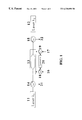
- FIG. 1 is a schematic view of a modulating apparatus in accordance with a first embodiment of the present invention
- FIG. 2 is a schematic view of a modulating apparatus in accordance with a second embodiment of the present invention.
- FIG. 3 is schematic view of a modulating apparatus in accordance with a third embodiment of the present invention.
- a first embodiment of the present invention includes first and second lasers 11 and 12 generating lights of continuous wavelengths ⁇ 1 and ⁇ 2 that represent first and second optical channels and a Mach-Zehnder type modulator 13 .
- a first optical circulator 14 is coupled between the first laser 11 and the Mach-Zehnder type modulator 13 .
- a second optical circulator 15 is provided between the second laser 12 and the Mach-Zehnder type modulator 13 .
- first and second RF sources generating electrical signals that represent subcarrier channels 16 and 17 for modulating first and second optical channels ⁇ 1 and ⁇ 2 are provided to the Mach-Zehnder type modulator 13 .
- Each of the subcarrier channels 16 and 17 may include one or more channels of electrical signals.
- a first electrical circulator 18 is coupled with the first subcarrier channels 16 and the Mach-Zehnder type modulator 13 .
- a second electrical circulator 19 is positioned between the second subcarrier channels 17 and the Mach-Zehnder type modulator 13 .
- a terminating resistor 20 is provided between the first and second electrical circulators 18 and 19 for suppressing counter-propagating electrical signals with respect to the optical channels.
- first and second electrical circulators 18 and 19 may be attached to each of the first and second electrical circulators 18 and 19 .
- a modulated first optical channel 22 is output from the second optical circulator 15 while a modulated second optical channel 21 is output from the first optical circulator 14 .
- the first and second optical circulators 14 and 15 also provide optical isolation between the first and second optical channels 11 and 12 .
- the apparatus in accordance with the first embodiment is described as follows.
- the electrical signals from the subcarrier channels 16 and 17 to be transmitted are co-propagated with a continuous wave optical signal from the first and second lasers 11 and 12 to achieve an intensity modulation in the optical domain.
- the electrical and optical signals are made to travel at nearly the same velocity, such as very high bandwidth ( ⁇ 40 GHz) operation, data transmission is limited only by electrode loss of the device.
- the electrical signals are made to counter-propagate with the optical signals, the electrical-optical interaction efficiency is degraded.
- significant nulls are introduced in the optical response as a function of frequency.
- the counter-propagating frequency response is about 15 to 40 dB below the co-propagating response.
- the frequency response and the magnitude and position of the nulls in the counter-propagating mode of operation are dependent on frequency and device design. Parameters relating to device design that affect the counter-propagating response of the modulator include the length of the device and the electrical effective index of the propagating electrical mode supported by the modulator.
- the electrical effective index is the ratio of the velocity of light in free space to the velocity of light in the electrode structure.
- lasers 11 and 12 generate two independent uncorrelated laser sources which are applied to two optical ports (for example, input and output fibers and not shown in drawings) of the modulator 13 .
- the first subcarrier channels 16 , and the second subcarrier channels 17 are electrical signals applied to the first and second electrical ports of modulator 13 for modulating optical wavelengths ⁇ 1 and ⁇ 2 , respectively.
- the electrical signals may be coupled to the modulator using, for example, RF connectors.
- the optical circulators 14 and 15 separate out the optical channels 11 and 12 after modulation.
- the electrical circulators 18 and 19 provide electrical isolation between the first and second subcarriers channels 16 and 17 by directing the counter-propagating electrical subcarrier channels to the terminating resistor 20 .
- the first subcarrier channels 16 for modulation on ⁇ 1 counter-propagates with the optical wavelength ⁇ 2 . Hence, it weakly interacts with ⁇ 2 .
- the second subcarrier channels 17 for modulation on ⁇ 2 counter-propagates with the optical wavelength ⁇ 2 , it weakly interacts with ⁇ 1 .
- the subcarrier frequencies may be in the range above 2 Ghz for some equipment.
- the frequency response can be measured for the cases of: (1) co-propagating electrical and optical signals, and (2) counter-propagating electrical and optical signals.
- the counter-propagating response will typically contain several nulls as a function of frequency.
- electrical isolation between the two subcarrier channels can be obtained with the modulator design of the second embodiment of the present invention, as shown in FIG. 2 .
- two independent electrodes 24 a and 24 b are formed on a Mach-Zehnder type modulator 22 and separated from each other.
- the electrical and optical signals always co-propagate with each other.
- the two electrical driving signals are applied such that they propagate in the same direction as the single optical signal. Therefore, terminating resistors are placed at the end of the each electrode to be positioned diametrically opposite to each other.
- terminating resistors 26 a and 26 b are placed diagonally opposite to each other.
- the implementation of two independent optical channels are modulated on one modulator in the configuration shown in FIG. 2 .
- the second embodiment of the present invention includes first and second lasers 21 a and 21 b that produce continuous lights of wavelengths ⁇ 1 and ⁇ 2 for first and second optical channels and a Mach-Zehnder modulator 22 .
- a first optical circulator 23 a is disposed between the first laser 21 a and the Mach-Zehnder modulator 22 .
- a second optical circulator 23 b is disposed between the second laser 21 b and the Mach-Zehnder modulator 22 .
- First and second electrical signals 25 a and 25 b typically RF signals, are applied to modulate the first and second optical channels. Unlike the first embodiment, electrical circulators are not required in the second embodiment as shown in FIG. 2.
- a dual electrode 24 a and 24 b is formed on the Mach-Zehnder modulator 22 and separated from each other. One end of each electrode is connected to a terminating resistor 26 a and 26 b while the other end of each electrode receives one of the first and second electrical signals 25 a and 25 b . Dark areas 28 a and 28 b other than the dual electrode 28 a and 28 b form ground electrodes.
- a first subcarrier signal 25 a for modulation on optical signal ⁇ 1 counter-propagate with optical signal ⁇ 2 , so that it interacts weakly with ⁇ 2 .
- interaction may be limited to the range of 15-40 dB.
- a second subcarrier channel 25 b for modulation on optical signal ⁇ 2 counter-propagate with optical signal ⁇ 1 , so that it interacts weakly with ⁇ 1 .
- the dual electrode designs were only to allow for the modulation of one optical channel on each modulator.
- the two electrodes were driven with independent drivers, the data applied to these electrodes was derived from the same data stream.
- FIG. 3 a third embodiment of two optical channels on one differentially driven modulator with adjustable chirp is demonstrated.
- the third embodiment of the present invention includes first and second continuous wave lasers 31 a and 31 b that generate laser light having wavelengths ⁇ 1 and ⁇ 2 for two optical channels and a Mach-Zehnder type modulator 32 .
- First and second optical circulators 33 a and 33 b are disposed between the first laser 31 a and the Mach-Zehnder type modulator 32 and the second laser 31 b and the Mach-Zehnder type modulator 32 , respectively.
- Subcarrier channels 35 a and 35 b are applied to electrical circulators 37 a and 37 b , respectively.
- Subcarrier channels 36 a and 36 b are applied to electrical circulators 36 a and 36 b .
- Subcarrier channels 35 a may be derived from the same source as subcarrier channels 35 b .
- subcarrier channels 36 a and 36 b may be derived from the same source.
- a weighting factor is applied to each of the subcarrier channels 35 a , 35 b , 36 a , and 36 b .
- the weighting factor for channels 35 a and 35 b is the ratio of the peak-to-peak drive voltages applied to these channels.
- the weighting factor for channels 36 a and 36 b is the ratio of the peak-to-peak drive voltages applied to these channels.
- the weighting factor determines a chirp parameter of the particular optical wavelength channel.
- the weighting factor of the subcarrier channels for modulation on ⁇ 1 may be designated as ⁇
- the weighting factor of the subcarrier channels for modulation on ⁇ 2 may be designated as ⁇ , where 0 ⁇
- subcarrier signals 35 a and 35 b for modulation on ⁇ 1 have a weighing factor of ⁇ .
- subcarrier signals 35 a and 35 b may be derived from the same source, e.g., the same data stream.
- subcarrier signals 36 a and 36 b for modulation on ⁇ 2 have a weighting factor of ⁇ are also derived from a common source, e.g., the same data stream, which may be different from the source intended for modulation on ⁇ 1 .
- the magnitude and sign of the weighting factors determine the chirp parameter of the modulator. For example, when ⁇ and ⁇ are ⁇ 0.5, complementary signals of equal amplitude are applied to each electrode 34 a and 34 b of the modulator 32 . This condition corresponds to differential driving with near zero chirp. By varying the values of ⁇ and ⁇ , different chirp parameters can be obtained.
- the weighting factors may be implemented, for example, by adjusting the amplitudes and phases of the subcarrier channels 35 a and 35 b and the subcarrier channels 36 a and 36 b .
- an electrical splitter may be used to implement the amplitude weighing factors.
- an electrical splitter may split an electrical signal into subcarrier channels 35 a and subcarrier channels 35 b , with the split ratio of the splitter determining the weighting factor.
- optical circulators 33 a and 33 b separate out the optical signals from the lasers 31 a and 31 b from the optical signals of outputs 41 a and 41 b .
- electrical circulators 37 a , 37 b , 38 a , and 37 b provide the necessary isolation between subcarrier signals 35 a and 35 b for modulation on the first optical signal ⁇ 1 and subcarrier signals 36 a and 36 b for modulation on the second optical signal ⁇ 2 .
- a terminating resistor 39 a is commonly connected to suppress counter-propagating electrical signals with respect to the optical signals.
- another terminating resistor 39 b is positioned between the electrical isolators 37 b and 38 b to suppress counter-propagating electrical signals with respect to the optical signals.
- separate terminating resistors may be coupled to each of electrical isolators 37 a and 37 b and/or electrical isolators 38 a and 38 b.
- one of the advantages of the present invention is that two independent optical channels are modulated in one modulator.
- the present invention has various applications in WDM transmission systems.
- one or more of the optical circulators may be replaced by a directional coupler or other device capable of providing isolation.
- one or more of the electrical circulators may be replaced, for example, by a passive device capable of providing isolation.
Abstract
Description
Claims (43)
Priority Applications (3)
| Application Number | Priority Date | Filing Date | Title |
|---|---|---|---|
| US09/412,980 US6330098B1 (en) | 1999-10-06 | 1999-10-06 | Apparatus for externally modulating two optical channels at the same time |
| AU77125/00A AU7712500A (en) | 1999-10-06 | 2000-09-25 | Apparatus for externally modulating two optical channels at the same time |
| PCT/US2000/026213 WO2001025846A1 (en) | 1999-10-06 | 2000-09-25 | Apparatus for externally modulating two optical channels at the same time |
Applications Claiming Priority (1)
| Application Number | Priority Date | Filing Date | Title |
|---|---|---|---|
| US09/412,980 US6330098B1 (en) | 1999-10-06 | 1999-10-06 | Apparatus for externally modulating two optical channels at the same time |
Publications (1)
| Publication Number | Publication Date |
|---|---|
| US6330098B1 true US6330098B1 (en) | 2001-12-11 |
Family
ID=23635281
Family Applications (1)
| Application Number | Title | Priority Date | Filing Date |
|---|---|---|---|
| US09/412,980 Expired - Fee Related US6330098B1 (en) | 1999-10-06 | 1999-10-06 | Apparatus for externally modulating two optical channels at the same time |
Country Status (3)
| Country | Link |
|---|---|
| US (1) | US6330098B1 (en) |
| AU (1) | AU7712500A (en) |
| WO (1) | WO2001025846A1 (en) |
Cited By (15)
| Publication number | Priority date | Publication date | Assignee | Title |
|---|---|---|---|---|
| US6493127B2 (en) * | 2001-01-11 | 2002-12-10 | Codeon Corporation | Modulation systems using dual channel optical modulators |
| US6525849B1 (en) * | 2000-01-28 | 2003-02-25 | National Science Council | Probe of two-way optical component network analyzer |
| US20050014472A1 (en) * | 2003-07-14 | 2005-01-20 | Photonicsystems, Inc. | Bi-directional signal interface |
| US20070189778A1 (en) * | 2006-02-14 | 2007-08-16 | Burns William K | Bi-directional signal interface using photonic coupler |
| US20080227410A1 (en) * | 2007-03-16 | 2008-09-18 | Photonic Systems, Inc. | Bi-directional signal interface and apparatus using same |
| US20090263081A1 (en) * | 2008-04-21 | 2009-10-22 | Photonic Systems, Inc. | Bi-directional signal interface with enhanced isolation |
| US8755750B2 (en) | 2010-05-22 | 2014-06-17 | Photonic Systems, Inc. | Wide-bandwidth signal canceller |
| US9209840B2 (en) | 2012-07-30 | 2015-12-08 | Photonic Systems, Inc. | Same-aperture any-frequency simultaneous transmit and receive communication system |
| US20160306201A1 (en) * | 2015-03-16 | 2016-10-20 | California Institute Of Technology | Differential ring modulator |
| US9935680B2 (en) | 2012-07-30 | 2018-04-03 | Photonic Systems, Inc. | Same-aperture any-frequency simultaneous transmit and receive communication system |
| US10158432B2 (en) | 2015-10-22 | 2018-12-18 | Photonic Systems, Inc. | RF signal separation and suppression system and method |
| US10374656B2 (en) | 2012-07-30 | 2019-08-06 | Photonic Systems, Inc. | Same-aperture any-frequency simultaneous transmit and receive communication system |
| US10551715B2 (en) | 2015-05-22 | 2020-02-04 | California Institute Of Technology | Optical ring modulator thermal tuning technique |
| US10623986B2 (en) | 2015-10-22 | 2020-04-14 | Photonic Systems, Inc. | RF signal separation and suppression system and method |
| US11539392B2 (en) | 2012-07-30 | 2022-12-27 | Photonic Systems, Inc. | Same-aperture any-frequency simultaneous transmit and receive communication system |
Citations (6)
| Publication number | Priority date | Publication date | Assignee | Title |
|---|---|---|---|---|
| US5074631A (en) | 1989-03-14 | 1991-12-24 | Fujitsu Limited | Optical modulator |
| US5101450A (en) | 1991-01-23 | 1992-03-31 | Gte Laboratories Incorporated | Quadrature optical phase modulators for lightwave systems |
| US5303079A (en) | 1992-04-09 | 1994-04-12 | At&T Bell Laboratories | Tunable chirp, lightwave modulator for dispersion compensation |
| US5408544A (en) | 1993-12-28 | 1995-04-18 | Fujitsu Limited | Optical modulator for producing a controllable chirp |
| US5787211A (en) | 1996-04-03 | 1998-07-28 | General Instrument Corporation Of Delaware | Optical modulator for CATV systems |
| US5812306A (en) | 1996-06-14 | 1998-09-22 | Ciena Corporation | Bidirectional WDM optical communication systems with bidirectional optical amplifiers |
-
1999
- 1999-10-06 US US09/412,980 patent/US6330098B1/en not_active Expired - Fee Related
-
2000
- 2000-09-25 WO PCT/US2000/026213 patent/WO2001025846A1/en active Application Filing
- 2000-09-25 AU AU77125/00A patent/AU7712500A/en not_active Abandoned
Patent Citations (6)
| Publication number | Priority date | Publication date | Assignee | Title |
|---|---|---|---|---|
| US5074631A (en) | 1989-03-14 | 1991-12-24 | Fujitsu Limited | Optical modulator |
| US5101450A (en) | 1991-01-23 | 1992-03-31 | Gte Laboratories Incorporated | Quadrature optical phase modulators for lightwave systems |
| US5303079A (en) | 1992-04-09 | 1994-04-12 | At&T Bell Laboratories | Tunable chirp, lightwave modulator for dispersion compensation |
| US5408544A (en) | 1993-12-28 | 1995-04-18 | Fujitsu Limited | Optical modulator for producing a controllable chirp |
| US5787211A (en) | 1996-04-03 | 1998-07-28 | General Instrument Corporation Of Delaware | Optical modulator for CATV systems |
| US5812306A (en) | 1996-06-14 | 1998-09-22 | Ciena Corporation | Bidirectional WDM optical communication systems with bidirectional optical amplifiers |
Non-Patent Citations (5)
| Title |
|---|
| A. H. Gnauck et al., "Dispersion Penalty Reduction Using an Optical Modulator with Adjustable Chirp," IEEE Photonics Technology Letters, vol. 3, No. 10, Oct. 1991, pp. 916-918. |
| G. H. Smith et al., "Overcoming Chromatic-Dispersion Effects in Fiber-Wireless Systems Incorporating External Modulators," IEEE Trans. On Microwave Theory and Techniques, vol. 45, No. 8, Aug. 1997, pp. 1410-1415. |
| G. K. Gopalakrishnan et al., "Performance and Modeling of Broadband LiNbO3 Traveling Wave Optical Intensity Modulators," Jour. Of Lightwave Technology, vol. 12, No. 10, Oct. 1994, pp. 1807-1819. |
| G. K. Gopalakrishnan et al., "Performance and Modeling of Resonantly Enhanced LiNbO3 Modulators for Low-Loss Analog Fiber-Optic Links," IEEE Trans. On Microwave Theory and Techniques, vol. 42, No. 12, Dec. 1994, pp. 2650-2656. |
| P. Jiang et al. "LiNbO3 Mach-Zehnder Modulators with Fixed Negative-Chirp," IEEE Photonics Technology Letters, vol. 8, No. 10, Oct. 1996, pp. 1319-1321. |
Cited By (28)
| Publication number | Priority date | Publication date | Assignee | Title |
|---|---|---|---|---|
| US6525849B1 (en) * | 2000-01-28 | 2003-02-25 | National Science Council | Probe of two-way optical component network analyzer |
| US6493127B2 (en) * | 2001-01-11 | 2002-12-10 | Codeon Corporation | Modulation systems using dual channel optical modulators |
| US8868006B2 (en) | 2003-07-14 | 2014-10-21 | Photonic Systems, Inc. | Bi-directional signal interface |
| US7826751B2 (en) | 2003-07-14 | 2010-11-02 | Photonic Systems, Inc. | Bi-directional signal interface |
| US20050014472A1 (en) * | 2003-07-14 | 2005-01-20 | Photonicsystems, Inc. | Bi-directional signal interface |
| US7555219B2 (en) | 2003-07-14 | 2009-06-30 | Photonic Systems, Inc. | Bi-directional signal interface |
| US20090247074A1 (en) * | 2003-07-14 | 2009-10-01 | Photonic Systems, Inc. | Bi-Directional Signal Interface |
| US20090274466A1 (en) * | 2003-07-14 | 2009-11-05 | Photonic Systems, Inc. | Bi-Directional Signal Interface |
| US7561803B2 (en) | 2006-02-14 | 2009-07-14 | Photonic Systems, Inc. | Bi-directional signal interface using photonic coupler |
| US20070189778A1 (en) * | 2006-02-14 | 2007-08-16 | Burns William K | Bi-directional signal interface using photonic coupler |
| US20080227410A1 (en) * | 2007-03-16 | 2008-09-18 | Photonic Systems, Inc. | Bi-directional signal interface and apparatus using same |
| US7809216B2 (en) | 2007-03-16 | 2010-10-05 | Photonic Systems, Inc. | Bi-directional signal interface and apparatus using same |
| US20090263081A1 (en) * | 2008-04-21 | 2009-10-22 | Photonic Systems, Inc. | Bi-directional signal interface with enhanced isolation |
| US8433163B2 (en) | 2008-04-21 | 2013-04-30 | Photonic Systems, Inc | Bi-directional signal interface with enhanced isolation |
| US8755750B2 (en) | 2010-05-22 | 2014-06-17 | Photonic Systems, Inc. | Wide-bandwidth signal canceller |
| US10374656B2 (en) | 2012-07-30 | 2019-08-06 | Photonic Systems, Inc. | Same-aperture any-frequency simultaneous transmit and receive communication system |
| US9935680B2 (en) | 2012-07-30 | 2018-04-03 | Photonic Systems, Inc. | Same-aperture any-frequency simultaneous transmit and receive communication system |
| US10425121B2 (en) | 2012-07-30 | 2019-09-24 | Photonic Systems, Inc. | Same-aperture any-frequency simultaneous transmit and receive communication system |
| US10651886B2 (en) | 2012-07-30 | 2020-05-12 | Photonic Systems, Inc. | Same-aperture any-frequency simultaneous transmit and receive communication system |
| US10879950B2 (en) | 2012-07-30 | 2020-12-29 | Photonic Systems, Inc. | Same-aperture any-frequency simultaneous transmit and receive communication system |
| US11539392B2 (en) | 2012-07-30 | 2022-12-27 | Photonic Systems, Inc. | Same-aperture any-frequency simultaneous transmit and receive communication system |
| US9209840B2 (en) | 2012-07-30 | 2015-12-08 | Photonic Systems, Inc. | Same-aperture any-frequency simultaneous transmit and receive communication system |
| US20160306201A1 (en) * | 2015-03-16 | 2016-10-20 | California Institute Of Technology | Differential ring modulator |
| US10527871B2 (en) * | 2015-03-16 | 2020-01-07 | California Institute Of Technology | Differential ring modulator |
| US10551715B2 (en) | 2015-05-22 | 2020-02-04 | California Institute Of Technology | Optical ring modulator thermal tuning technique |
| US10158432B2 (en) | 2015-10-22 | 2018-12-18 | Photonic Systems, Inc. | RF signal separation and suppression system and method |
| US11817989B2 (en) | 2015-10-22 | 2023-11-14 | Photonic Systems, Inc. | RF signal separation and suppression system and method |
| US10623986B2 (en) | 2015-10-22 | 2020-04-14 | Photonic Systems, Inc. | RF signal separation and suppression system and method |
Also Published As
| Publication number | Publication date |
|---|---|
| WO2001025846A1 (en) | 2001-04-12 |
| AU7712500A (en) | 2001-05-10 |
Similar Documents
| Publication | Publication Date | Title |
|---|---|---|
| US6330098B1 (en) | Apparatus for externally modulating two optical channels at the same time | |
| US7302120B2 (en) | Optical modulator | |
| US6262834B1 (en) | Wideband single sideband modulation of optical carriers | |
| Williamson et al. | RF photonics | |
| US5420868A (en) | Suppression of brillouin scattering in lightwave transmission system | |
| US5109441A (en) | Fiber optic external modulator | |
| EP0950167B1 (en) | Variable chirp optical modulator using single modulation source | |
| EP0387832B1 (en) | Optical modulator | |
| US6091864A (en) | Linear optical modulator for providing chirp-free optical signals | |
| US6052496A (en) | Integrated optical modulators | |
| US5970185A (en) | Optical switches, modulators and transmitters | |
| US5101291A (en) | Optical frequency conversion device | |
| KR100288443B1 (en) | Optical modulator using isolator and optical transmitter comprising it | |
| JPH07199133A (en) | Optical modulator | |
| US6341031B1 (en) | Optical pulse generation using a high order function waveguide interferometer | |
| US20080199124A1 (en) | OPTICAL DEVICE FOR GENERATING AND MODULATING THz AND OTHER HIGH FREQUENCY SIGNALS | |
| CA2229516C (en) | Compensation of dispersion | |
| US6493127B2 (en) | Modulation systems using dual channel optical modulators | |
| US7570843B2 (en) | Optical modulation element module | |
| WO1988003278A1 (en) | Optical signal modulation device | |
| Loayssa et al. | Single-sideband suppressed-carrier modulation using a single-electrode electrooptic modulator | |
| JPH0961766A (en) | Semiconductor optical modulator | |
| US5911016A (en) | Polarization scrambler and integrated optical circuit making use thereof | |
| US6535316B1 (en) | Generation of high-speed digital optical signals | |
| EP0491272B1 (en) | Optical transmitter |
Legal Events
| Date | Code | Title | Description |
|---|---|---|---|
| AS | Assignment |
Owner name: CODEON CORPORATION, MARYLAND Free format text: ASSIGNMENT OF ASSIGNORS INTEREST;ASSIGNOR:GOPALKRISHNAN, GANESH K.;REEL/FRAME:010306/0335 Effective date: 19991005 |
|
| AS | Assignment |
Owner name: COMERICA BANK, CALIFORNIA Free format text: INTELLECTUAL PROPERTY SECURITY AGREEMENT;ASSIGNOR:COVEGA CORPORATION;REEL/FRAME:015766/0083 Effective date: 20050210 |
|
| FPAY | Fee payment |
Year of fee payment: 4 |
|
| AS | Assignment |
Owner name: SQUARE 1 BANK, NORTH CAROLINA Free format text: ASSIGNMENT OF ASSIGNORS INTEREST;ASSIGNOR:COVEGA CORPORATION;REEL/FRAME:019265/0490 Effective date: 20060807 |
|
| FEPP | Fee payment procedure |
Free format text: PAYOR NUMBER ASSIGNED (ORIGINAL EVENT CODE: ASPN); ENTITY STATUS OF PATENT OWNER: LARGE ENTITY |
|
| AS | Assignment |
Owner name: COVEGA CORPORATION, MARYLAND Free format text: CHANGE OF NAME;ASSIGNOR:CODEON CORPORATION;REEL/FRAME:022354/0099 Effective date: 20030314 |
|
| AS | Assignment |
Owner name: COVEGA CORPORATION, MARYLAND Free format text: RELEASE BY SECURED PARTY;ASSIGNOR:SQUARE BANK 1;REEL/FRAME:022408/0516 Effective date: 20090317 |
|
| AS | Assignment |
Owner name: COVEGA CORPORATION, NEW JERSEY Free format text: RELEASE BY SECURED PARTY;ASSIGNOR:COMERICA BANK;REEL/FRAME:022416/0253 Effective date: 20090317 |
|
| AS | Assignment |
Owner name: THORLABS QUANTUM ELECTRONICS, INC., NEW JERSEY Free format text: ASSIGNMENT OF ASSIGNORS INTEREST;ASSIGNOR:COVEGA CORPORATION;REEL/FRAME:022427/0994 Effective date: 20090317 |
|
| FPAY | Fee payment |
Year of fee payment: 8 |
|
| REMI | Maintenance fee reminder mailed | ||
| LAPS | Lapse for failure to pay maintenance fees | ||
| STCH | Information on status: patent discontinuation |
Free format text: PATENT EXPIRED DUE TO NONPAYMENT OF MAINTENANCE FEES UNDER 37 CFR 1.362 |
|
| FP | Lapsed due to failure to pay maintenance fee |
Effective date: 20131211 |