US6331690B1 - Process for producing single-wall carbon nanotubes uniform in diameter and laser ablation apparatus used therein - Google Patents
Process for producing single-wall carbon nanotubes uniform in diameter and laser ablation apparatus used therein Download PDFInfo
- Publication number
- US6331690B1 US6331690B1 US09/562,959 US56295900A US6331690B1 US 6331690 B1 US6331690 B1 US 6331690B1 US 56295900 A US56295900 A US 56295900A US 6331690 B1 US6331690 B1 US 6331690B1
- Authority
- US
- United States
- Prior art keywords
- vapor
- carbon
- source
- laser
- reactor
- Prior art date
- Legal status (The legal status is an assumption and is not a legal conclusion. Google has not performed a legal analysis and makes no representation as to the accuracy of the status listed.)
- Expired - Lifetime
Links
Images


Classifications
-
- B—PERFORMING OPERATIONS; TRANSPORTING
- B01—PHYSICAL OR CHEMICAL PROCESSES OR APPARATUS IN GENERAL
- B01J—CHEMICAL OR PHYSICAL PROCESSES, e.g. CATALYSIS OR COLLOID CHEMISTRY; THEIR RELEVANT APPARATUS
- B01J19/00—Chemical, physical or physico-chemical processes in general; Their relevant apparatus
- B01J19/08—Processes employing the direct application of electric or wave energy, or particle radiation; Apparatus therefor
- B01J19/12—Processes employing the direct application of electric or wave energy, or particle radiation; Apparatus therefor employing electromagnetic waves
- B01J19/121—Coherent waves, e.g. laser beams
-
- B—PERFORMING OPERATIONS; TRANSPORTING
- B82—NANOTECHNOLOGY
- B82Y—SPECIFIC USES OR APPLICATIONS OF NANOSTRUCTURES; MEASUREMENT OR ANALYSIS OF NANOSTRUCTURES; MANUFACTURE OR TREATMENT OF NANOSTRUCTURES
- B82Y30/00—Nanotechnology for materials or surface science, e.g. nanocomposites
-
- B—PERFORMING OPERATIONS; TRANSPORTING
- B82—NANOTECHNOLOGY
- B82Y—SPECIFIC USES OR APPLICATIONS OF NANOSTRUCTURES; MEASUREMENT OR ANALYSIS OF NANOSTRUCTURES; MANUFACTURE OR TREATMENT OF NANOSTRUCTURES
- B82Y40/00—Manufacture or treatment of nanostructures
-
- C—CHEMISTRY; METALLURGY
- C01—INORGANIC CHEMISTRY
- C01B—NON-METALLIC ELEMENTS; COMPOUNDS THEREOF; METALLOIDS OR COMPOUNDS THEREOF NOT COVERED BY SUBCLASS C01C
- C01B32/00—Carbon; Compounds thereof
- C01B32/15—Nano-sized carbon materials
- C01B32/158—Carbon nanotubes
- C01B32/16—Preparation
- C01B32/162—Preparation characterised by catalysts
-
- B—PERFORMING OPERATIONS; TRANSPORTING
- B01—PHYSICAL OR CHEMICAL PROCESSES OR APPARATUS IN GENERAL
- B01J—CHEMICAL OR PHYSICAL PROCESSES, e.g. CATALYSIS OR COLLOID CHEMISTRY; THEIR RELEVANT APPARATUS
- B01J2219/00—Chemical, physical or physico-chemical processes in general; Their relevant apparatus
- B01J2219/08—Processes employing the direct application of electric or wave energy, or particle radiation; Apparatus therefor
- B01J2219/0871—Heating or cooling of the reactor
-
- B—PERFORMING OPERATIONS; TRANSPORTING
- B01—PHYSICAL OR CHEMICAL PROCESSES OR APPARATUS IN GENERAL
- B01J—CHEMICAL OR PHYSICAL PROCESSES, e.g. CATALYSIS OR COLLOID CHEMISTRY; THEIR RELEVANT APPARATUS
- B01J2219/00—Chemical, physical or physico-chemical processes in general; Their relevant apparatus
- B01J2219/08—Processes employing the direct application of electric or wave energy, or particle radiation; Apparatus therefor
- B01J2219/0873—Materials to be treated
- B01J2219/0881—Two or more materials
- B01J2219/0883—Gas-gas
-
- B—PERFORMING OPERATIONS; TRANSPORTING
- B01—PHYSICAL OR CHEMICAL PROCESSES OR APPARATUS IN GENERAL
- B01J—CHEMICAL OR PHYSICAL PROCESSES, e.g. CATALYSIS OR COLLOID CHEMISTRY; THEIR RELEVANT APPARATUS
- B01J2219/00—Chemical, physical or physico-chemical processes in general; Their relevant apparatus
- B01J2219/08—Processes employing the direct application of electric or wave energy, or particle radiation; Apparatus therefor
- B01J2219/0873—Materials to be treated
- B01J2219/0892—Materials to be treated involving catalytically active material
-
- C—CHEMISTRY; METALLURGY
- C01—INORGANIC CHEMISTRY
- C01B—NON-METALLIC ELEMENTS; COMPOUNDS THEREOF; METALLOIDS OR COMPOUNDS THEREOF NOT COVERED BY SUBCLASS C01C
- C01B2202/00—Structure or properties of carbon nanotubes
- C01B2202/02—Single-walled nanotubes
-
- C—CHEMISTRY; METALLURGY
- C01—INORGANIC CHEMISTRY
- C01B—NON-METALLIC ELEMENTS; COMPOUNDS THEREOF; METALLOIDS OR COMPOUNDS THEREOF NOT COVERED BY SUBCLASS C01C
- C01B2202/00—Structure or properties of carbon nanotubes
- C01B2202/20—Nanotubes characterized by their properties
- C01B2202/36—Diameter
-
- Y—GENERAL TAGGING OF NEW TECHNOLOGICAL DEVELOPMENTS; GENERAL TAGGING OF CROSS-SECTIONAL TECHNOLOGIES SPANNING OVER SEVERAL SECTIONS OF THE IPC; TECHNICAL SUBJECTS COVERED BY FORMER USPC CROSS-REFERENCE ART COLLECTIONS [XRACs] AND DIGESTS
- Y10—TECHNICAL SUBJECTS COVERED BY FORMER USPC
- Y10S—TECHNICAL SUBJECTS COVERED BY FORMER USPC CROSS-REFERENCE ART COLLECTIONS [XRACs] AND DIGESTS
- Y10S977/00—Nanotechnology
- Y10S977/84—Manufacture, treatment, or detection of nanostructure
- Y10S977/842—Manufacture, treatment, or detection of nanostructure for carbon nanotubes or fullerenes
- Y10S977/844—Growth by vaporization or dissociation of carbon source using a high-energy heat source, e.g. electric arc, laser, plasma, e-beam
Definitions
- This invention relates to a carbon nanotube and, more particularly, to a process for producing a carbon nanotube and a laser ablation apparatus used therein.
- a typical example of the process for producing carbon nanotubes is disclosed by Andreas Thess et al in “Crystalline Ropes of Metallic Carbon Nanotubes”, Science, vol. 273, pages 483 to 487, Jul. 26, 1996.
- Metal catalyst particle such as nickel-cobalt alloy is mixed with graphite powder at a predetermined percentage, and the mixture is pressed so as to obtain a pellet.
- a laser beam is radiated to the pellet. The laser beam evaporates the carbon and the nickel-cobalt alloy, and the carbon vapor is condensed in the presence of the metal catalyst.
- Single-wall carbon nanotubes are found in the condensation. A problem is encountered in the prior art process in that the single-wall carbon nanotubes are not constant in diameter.
- the present inventors contemplated the problem inherent in the prior art process, and noticed that the ratio between the carbon vapor and the metal catalyst vapor was varied with time due to absorption of the laser light.
- the graphite powder was black, and took up the laser light rather than the metal catalyst.
- the laser light thus absorbed raised the temperature rapidly rather than the metal catalyst, and the metal catalyst was left in the surface portion.
- the metal catalyst layer reflected the laser light, and the graphite powder was less sublimated. This resulted in that the purity of carbon was not uniform. For this reason, the carbon nanotubes did not become constant in diameter.
- the present invention proposes to independently evaporate carbon and metal catalyst.
- a process for producing carbon nanotubes comprising the steps of preparing a source of carbon vapor and a source of catalyst vapor physically separated from each other, radiating laser beams to the source of carbon vapor and the source of catalyst vapor so as to generate a carbon vapor/cluster and a catalyst vapor/cluster, and allowing the carbon vapor/cluster to be mixed with the catalyst vapor/cluster so as to form the carbon vapor/cluster into carbon nanotubes.
- a laser ablation system for producing carbon nanotubes comprising a reactor having an air-tight chamber where a source of carbon vapor and a source of catalyst vapor are separately provided, a laser beam generator provided for the reactor and radiating laser beams to the source of carbon vapor and the source of catalyst vapor for producing a carbon vapor/cluster and a catalyst vapor/cluster from the source of carbon vapor and the source of catalyst vapor, respectively, an evacuating sub-system connected to the reactor for evacuating a gaseous mixture from the air-tight chamber, a carrier gas supply sub-system connected to the reactor supplying carrier gas to the air-tight chamber for forming a carrier gas flow in the air-tight chamber, and a collector provided in the carrier gas flow and capturing carbon nanotubes formed from the carbon vapor/cluster in the presence of the catalyst vapor/cluster and carried on the carrier gas flow.
- FIGS. 1A to 1 C are schematic views showing a process for producing carbon nanotubes according to the present invention.
- FIG. 2 is a schematic view showing a carbon pellet and metal catalyst pellet independently radiated with laser beams.
- FIGS. 1A to 1 C illustrate a process for producing carbon nanotubes embodying the present invention.
- the process starts with preparation of a carbon pellet 1 , a metal catalyst pellet 2 and a laser ablation system 3 .
- the carbon pellet 1 , the metal catalyst pellet 2 and the laser ablation system 3 are detailed hereinbelow with reference to FIG. 1 A.
- the carbon pellet is formed from graphite.
- the graphite consists of carbon, and is shaped into the carbon pellet by using a standard pelleting machine.
- the carbon pellet 1 has a plate-like configuration, and is 10 millimeters long and 3 to 5 millimeters wide.
- the metal catalyst pellet 2 is formed of nickel-cobalt alloy.
- the nickel and the cobalt are regulated to the atomic ratio of 1:1.
- Nickel, cobalt, platinum, palladium and alloys thereof are available for the metal catalyst.
- the alloy contains at least two elements selected from nickel, cobalt, platinum and palladium.
- the metal catalyst is also shaped into a plate-like configuration by using the pelleting machine, and is equal in dimensions to the carbon pellet 1 .
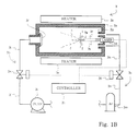
- the laser ablation system 3 includes a reactor 3 a, an evacuating sub-system 3 b, an inert gas supply sub-system 3 c, a laser beam generator 3 d, a heater 3 e, a collector 3 f, a spacer 3 g (see FIGS. 1B and 1C) and a controller 3 h.
- the evacuating sub-system 3 b and the inert gas supply sub-system 3 c create vacuum in the reactor, and cause inert gas to flow through the reactor 1 as indicated by arrows AR 1 .
- the heater 3 e maintains the inside of the reactor 3 a at a predetermined temperature range.
- the carbon pellet 1 and the metal catalyst pellet 2 are separately provided inside the reactor, and the spacer 3 g of quartz plate is provided between the carbon pellet 1 and the metal catalyst pellet 2 .
- the spacer 3 g is 0.3 millimeter thick.
- the laser beam generator 3 d radiates laser beams 3 r/ 3 s to the carbon pellet 1 and the metal catalyst pellet 2 , respectively.
- Carbon vapor and catalyst vapor are generated from the carbon pellet 1 and the metal catalyst pellet 2 , respectively, and condensate is captured by the collector 3 f.
- the process sequence is controlled by the controller 3 h.
- the reactor 3 a is formed of quartz or ceramic, and has a cylindrical configuration. Any material is available for the reactor 3 a in so far as it is hardly eroded in the ambience created in the reactor 3 a. Although the reactor 3 a is not limited to the cylindrical configuration, the cylindrical configuration is desirable.
- the evacuating sub-system 3 b includes a rotary vacuum pump 3 i, a pipe 3 j connected between the reactor 3 a and the rotary vacuum pump 3 i and an electromagnetic flow control valve 3 k inserted into the pipe 3 j.
- the inert gas supply sub-system 3 c includes a reservoir tank 3 m for inert gas such as, for example, argon gas, a pipe connected between the reservoir tank 3 m and the reactor 3 a and an electromagnetic flow control valve 3 o inserted into the pipe 3 n.
- the electromagnetic flow control valve 3 o supplies the argon gas to the inlet nozzle 3 p at 0.2 to 0.5 litter per minute, and the argon gas is blown off into the reactor 3 a.
- the rotary vacuum pump 3 i evacuates the argon gas
- the electromagnetic flow control valve 3 k evacuates the argon gas
- the electromagnetic flow control value 3 k maintains the argon gas in the reactor 3 a at 500 torr to 600 torr.
- the laser beam generator 3 d generates laser light, and radiates laser beams 3 r/ 3 s to the carbon pellet 1 and the metal catalyst pellet 2 , respectively.
- the laser beam generator 3 d includes a laser light emitting element formed of Nd contained single crystalline YAG (Yttrium Aluminum Garnet), and the laser light emitting element radiates laser light pulses 3 r/ 3 s.
- the laser light has 532 nanometer wavelength, and oscillates at 10 Hz.
- the pulse width ranges from 7 nanoseconds to 10 nanoseconds, and the power is regulated to 1.2 to 9.2 J/pulse.
- the laser beam 3 r/ 3 s has cross section of 0.2 cm 2 .
- the heater 3 e heats the reactor 3 a, and the controller 3 h maintains the inside of the reactor 3 a around 1200 degrees in centigrade.
- the heater 3 e may be implemented by an oven.
- the carbon pellet 1 , the metal catalyst pellet 2 and the laser ablation system 3 are prepared, an operator inserts the carbon pellet 1 and the metal catalyst pellet 2 into the reactor 3 a.
- the carbon pellet 1 and the metal catalyst pellet 2 symmetrically decline with respect to the center line of the reactor 3 a, and the major surface of the carbon pellet 1 is opposed through the spacer 3 g to the concave surface of the metal catalyst pellet 2 as shown in FIG. 2 .
- the reactor 3 a is closed, and the rotary vacuum pump 3 i evacuates the air from the reactor 3 a.
- the inert gas supply system 3 c supplies the argon gas at 0.5 litter/minute.
- the evacuating sub-system 3 b cooperates with the inert gas supply system 3 c, and maintain the inside of the reactor 3 a at 600 mmHg.
- the argon gas flows from the nozzle 3 p toward the collector 3 f.
- the laser beam generator 3 d radiates the laser beams 3 r/ 3 s to the carbon pellet 1 and the metal catalyst pellet 2 .
- the pulse width and the power are adjusted to 10 nanosecond and 50 mJ/pulse ⁇ cm 2 .
- the laser beams 3 r/ 3 s directly heat the carbon pellet 1 and the metal catalyst pellet 2 , and carbon vapor/cluster 4 and nickel-cobalt vapor/cluster 5 are constantly generated from the carbon pellet 1 and the metal catalyst pellet 2 , respectively, as shown in FIG. 1 B.
- the argon gas carries the carbon vapor/cluster 4 and the nickel-cobalt vapor/cluster 5 toward the collector 3 f.
- the carbon vapor/cluster 4 are mixed with the nickel-cobalt vapor/cluster 5 , and forms into single-wall carbon nanotubes 6 .
- the single-wall carbon nanotubes 6 are carried toward the collector 3 f, and are captured by the collector 3 f as shown in FIG. 1 C.
- the carbon vapor/cluster 4 and the nickel-cobalt vapor/cluster 5 are constant in mass, and keeps the content of carbon in the condensate or the single-wall carbon nanotubes 6 constant. This results in the constant diameter of the single-wall carbon nanotubes 6 .
- the carbon pellet 1 and the metal catalyst pellet 2 are used in the process according to the present invention, and make the single-wall carbon nanotubes constant in diameter.
- the carbon and the metal catalyst may be in the form of powder.
- the carbon pellet and the metal catalyst pellet may have a semi-column configuration.
Abstract
Single-wall carbon nanotubes are produced from carbon vapor in the presence of nickel-cobalt catalyst vapor, and the carbon vapor and the nickel-cobalt catalyst vapor are constantly generated from a carbon pellet and a nickel-cobalt pellet under radiation of YAG laser beams so that the single-wall carbon nanotubes are constant in diameter.
Description
This is a divisional of application Ser. No. 09/177,790 filed Oct. 23, 1998, the disclosure of which is incorporated herein by reference.
Priority is claimed from Dec. 22, 1997 based on JP Application No. 9-352833. The priority document was filed in parent Application No. 09/177,790.
This invention relates to a carbon nanotube and, more particularly, to a process for producing a carbon nanotube and a laser ablation apparatus used therein.
A typical example of the process for producing carbon nanotubes is disclosed by Andreas Thess et al in “Crystalline Ropes of Metallic Carbon Nanotubes”, Science, vol. 273, pages 483 to 487, Jul. 26, 1996. Metal catalyst particle such as nickel-cobalt alloy is mixed with graphite powder at a predetermined percentage, and the mixture is pressed so as to obtain a pellet. A laser beam is radiated to the pellet. The laser beam evaporates the carbon and the nickel-cobalt alloy, and the carbon vapor is condensed in the presence of the metal catalyst. Single-wall carbon nanotubes are found in the condensation. A problem is encountered in the prior art process in that the single-wall carbon nanotubes are not constant in diameter.
It is therefore an important object of the present invention to provide a process for producing single-wall carbon nanotubes, which is uniform in diameter.
The present inventors contemplated the problem inherent in the prior art process, and noticed that the ratio between the carbon vapor and the metal catalyst vapor was varied with time due to absorption of the laser light. The graphite powder was black, and took up the laser light rather than the metal catalyst. The laser light thus absorbed raised the temperature rapidly rather than the metal catalyst, and the metal catalyst was left in the surface portion. The metal catalyst layer reflected the laser light, and the graphite powder was less sublimated. This resulted in that the purity of carbon was not uniform. For this reason, the carbon nanotubes did not become constant in diameter.
To accomplish the object, the present invention proposes to independently evaporate carbon and metal catalyst.
In accordance with one aspect of the present invention, there is provided a process for producing carbon nanotubes comprising the steps of preparing a source of carbon vapor and a source of catalyst vapor physically separated from each other, radiating laser beams to the source of carbon vapor and the source of catalyst vapor so as to generate a carbon vapor/cluster and a catalyst vapor/cluster, and allowing the carbon vapor/cluster to be mixed with the catalyst vapor/cluster so as to form the carbon vapor/cluster into carbon nanotubes.
In accordance with another aspect of the present invention, there is provided a laser ablation system for producing carbon nanotubes comprising a reactor having an air-tight chamber where a source of carbon vapor and a source of catalyst vapor are separately provided, a laser beam generator provided for the reactor and radiating laser beams to the source of carbon vapor and the source of catalyst vapor for producing a carbon vapor/cluster and a catalyst vapor/cluster from the source of carbon vapor and the source of catalyst vapor, respectively, an evacuating sub-system connected to the reactor for evacuating a gaseous mixture from the air-tight chamber, a carrier gas supply sub-system connected to the reactor supplying carrier gas to the air-tight chamber for forming a carrier gas flow in the air-tight chamber, and a collector provided in the carrier gas flow and capturing carbon nanotubes formed from the carbon vapor/cluster in the presence of the catalyst vapor/cluster and carried on the carrier gas flow.
The features and advantages of the process and the laser ablation apparatus will be more clearly understood from the following description taken in conjunction with the accompanying drawings in which:
FIGS. 1A to 1C are schematic views showing a process for producing carbon nanotubes according to the present invention; and
FIG. 2 is a schematic view showing a carbon pellet and metal catalyst pellet independently radiated with laser beams.
FIGS. 1A to 1C illustrate a process for producing carbon nanotubes embodying the present invention. The process starts with preparation of a carbon pellet 1, a metal catalyst pellet 2 and a laser ablation system 3. The carbon pellet 1, the metal catalyst pellet 2 and the laser ablation system 3 are detailed hereinbelow with reference to FIG. 1A.
The carbon pellet is formed from graphite. The graphite consists of carbon, and is shaped into the carbon pellet by using a standard pelleting machine. The carbon pellet 1 has a plate-like configuration, and is 10 millimeters long and 3 to 5 millimeters wide.
The metal catalyst pellet 2 is formed of nickel-cobalt alloy. The nickel and the cobalt are regulated to the atomic ratio of 1:1. Nickel, cobalt, platinum, palladium and alloys thereof are available for the metal catalyst. The alloy contains at least two elements selected from nickel, cobalt, platinum and palladium. The metal catalyst is also shaped into a plate-like configuration by using the pelleting machine, and is equal in dimensions to the carbon pellet 1.
The laser ablation system 3 includes a reactor 3 a, an evacuating sub-system 3 b, an inert gas supply sub-system 3 c, a laser beam generator 3 d, a heater 3 e, a collector 3 f, a spacer 3 g (see FIGS. 1B and 1C) and a controller 3 h. The evacuating sub-system 3 b and the inert gas supply sub-system 3 c create vacuum in the reactor, and cause inert gas to flow through the reactor 1 as indicated by arrows AR1. The heater 3 e maintains the inside of the reactor 3 a at a predetermined temperature range. The carbon pellet 1 and the metal catalyst pellet 2 are separately provided inside the reactor, and the spacer 3 g of quartz plate is provided between the carbon pellet 1 and the metal catalyst pellet 2. The spacer 3 g is 0.3 millimeter thick. The laser beam generator 3 d radiates laser beams 3 r/ 3 s to the carbon pellet 1 and the metal catalyst pellet 2, respectively. Carbon vapor and catalyst vapor are generated from the carbon pellet 1 and the metal catalyst pellet 2, respectively, and condensate is captured by the collector 3 f. The process sequence is controlled by the controller 3 h.
The reactor 3 a is formed of quartz or ceramic, and has a cylindrical configuration. Any material is available for the reactor 3 a in so far as it is hardly eroded in the ambience created in the reactor 3 a. Although the reactor 3 a is not limited to the cylindrical configuration, the cylindrical configuration is desirable.
The evacuating sub-system 3 b includes a rotary vacuum pump 3 i, a pipe 3 j connected between the reactor 3 a and the rotary vacuum pump 3 i and an electromagnetic flow control valve 3 k inserted into the pipe 3 j. On the other hand, the inert gas supply sub-system 3 c includes a reservoir tank 3 m for inert gas such as, for example, argon gas, a pipe connected between the reservoir tank 3 m and the reactor 3 a and an electromagnetic flow control valve 3 o inserted into the pipe 3 n. The electromagnetic flow control valve 3 o supplies the argon gas to the inlet nozzle 3 p at 0.2 to 0.5 litter per minute, and the argon gas is blown off into the reactor 3 a. The rotary vacuum pump 3 i evacuates the argon gas, and the electromagnetic flow control valve 3 k evacuates the argon gas, and the electromagnetic flow control value 3 k maintains the argon gas in the reactor 3 a at 500 torr to 600 torr.
The laser beam generator 3 d generates laser light, and radiates laser beams 3 r/ 3 s to the carbon pellet 1 and the metal catalyst pellet 2, respectively. The laser beam generator 3 d includes a laser light emitting element formed of Nd contained single crystalline YAG (Yttrium Aluminum Garnet), and the laser light emitting element radiates laser light pulses 3 r/ 3 s. The laser light has 532 nanometer wavelength, and oscillates at 10 Hz. The pulse width ranges from 7 nanoseconds to 10 nanoseconds, and the power is regulated to 1.2 to 9.2 J/pulse. The laser beam 3 r/ 3 s has cross section of 0.2 cm2.
The heater 3 e heats the reactor 3 a, and the controller 3 h maintains the inside of the reactor 3 a around 1200 degrees in centigrade. The heater 3 e may be implemented by an oven.
When the carbon pellet 1, the metal catalyst pellet 2 and the laser ablation system 3 are prepared, an operator inserts the carbon pellet 1 and the metal catalyst pellet 2 into the reactor 3 a. The carbon pellet 1 and the metal catalyst pellet 2 symmetrically decline with respect to the center line of the reactor 3 a, and the major surface of the carbon pellet 1 is opposed through the spacer 3 g to the concave surface of the metal catalyst pellet 2 as shown in FIG. 2.
The reactor 3 a is closed, and the rotary vacuum pump 3 i evacuates the air from the reactor 3 a. When the vacuum is developed in the reactor 3 a, the inert gas supply system 3 c supplies the argon gas at 0.5 litter/minute. The evacuating sub-system 3 b cooperates with the inert gas supply system 3 c, and maintain the inside of the reactor 3 a at 600 mmHg. The argon gas flows from the nozzle 3 p toward the collector 3 f.
Subsequently, the laser beam generator 3 d radiates the laser beams 3 r/ 3 s to the carbon pellet 1 and the metal catalyst pellet 2. In this instance, the pulse width and the power are adjusted to 10 nanosecond and 50 mJ/pulse·cm2. The laser beams 3 r/ 3 s directly heat the carbon pellet 1 and the metal catalyst pellet 2, and carbon vapor/cluster 4 and nickel-cobalt vapor/cluster 5 are constantly generated from the carbon pellet 1 and the metal catalyst pellet 2, respectively, as shown in FIG. 1B.
The argon gas carries the carbon vapor/cluster 4 and the nickel-cobalt vapor/cluster 5 toward the collector 3 f. The carbon vapor/cluster 4 are mixed with the nickel-cobalt vapor/cluster 5, and forms into single-wall carbon nanotubes 6. The single-wall carbon nanotubes 6 are carried toward the collector 3 f, and are captured by the collector 3 f as shown in FIG. 1C. The carbon vapor/cluster 4 and the nickel-cobalt vapor/cluster 5 are constant in mass, and keeps the content of carbon in the condensate or the single-wall carbon nanotubes 6 constant. This results in the constant diameter of the single-wall carbon nanotubes 6.
As will be appreciated from the foregoing description, the carbon pellet 1 and the metal catalyst pellet 2 are used in the process according to the present invention, and make the single-wall carbon nanotubes constant in diameter.
Although particular embodiments of the present invention have been shown and described, it will be apparent to those skilled in the art that various changes and modifications may be made without departing from the spirit and scope of the present invention.
It is required for the process according to the present invention to separately vaporize the carbon and the metal catalyst. However, this requirement does not means the carbon and the metal catalyst respectively formed into pellets. The carbon and the metal catalyst may be in the form of powder.
The carbon pellet and the metal catalyst pellet may have a semi-column configuration.
Claims (7)
1. A laser ablation system for producing carbon nanotubes, comprising:
a reactor having an air-tight chamber where a source of carbon vapor and a source of catalyst vapor are separately provided;
a laser beam generator provided for said reactor and radiating laser beams to said source of carbon vapor and said source of catalyst vapor for producing a carbon vapor/cluster and a catalyst vapor/cluster from said source of carbon vapor and said source of catalyst vapor, respectively;
an evacuating sub-system connected to said reactor for evacuating a gaseous mixture from said air-tight chamber;
a carrier gas supply sub-system connected to said reactor supplying carrier gas to said air-tight chamber for forming a carrier gas flow in said air-tight chamber; and
a collector provided in said carrier gas flow and capturing carbon nanotubes formed from said carbon vapor/cluster in the presence of said catalyst vapor/cluster and carried on said carrier gas flow.
2. The laser ablation system as set forth in claim 1, in which said carrier gas supply system includes a source of inert gas, and said evacuating sub-system and said carrier gas supply system cooperate with each other so as to flow an inert gas at 0.2 to 0.5 liter per minute at 500 to 600 torr in said air-tight chamber.
3. The laser ablation system as set forth in claim 1, in which said reactor is formed of a material selected from the group consisting of quartz and ceramics.
4. The laser ablation system as set forth in claim 1, in which said laser beam generator produces laser pulse trains from a YAG laser for said laser beams, and the laser pulse trains have a wavelength of 532 nanometers, a frequency of 10 Hz, a pulse width of 7 to 10 nanoseconds and a power of 1.2 to 9.1 J/pulse.
5. The laser ablation system as set forth in claim 4, further comprising a heater for heating said air-tight chamber to at least 1200 degrees in centigrade.
6. The laser ablation system as set forth in claim 1, in which a carbon pellet and a catalyst pellet serve as said source of carbon vapor and said source of catalyst vapor, respectively.
7. The laser ablation system as set forth in claim 6, in which said catalyst pellet is formed of a material selected from the group consisting of nickel, cobalt, platinum, palladium and alloys containing at least two metals of said nickel, said cobalt, said platinum and said palladium.
Priority Applications (1)
| Application Number | Priority Date | Filing Date | Title |
|---|---|---|---|
| US09/562,959 US6331690B1 (en) | 1997-12-22 | 2000-05-03 | Process for producing single-wall carbon nanotubes uniform in diameter and laser ablation apparatus used therein |
Applications Claiming Priority (4)
| Application Number | Priority Date | Filing Date | Title |
|---|---|---|---|
| JP09352833A JP3077655B2 (en) | 1997-12-22 | 1997-12-22 | Apparatus and method for producing carbon nanotube |
| JP9-352833 | 1997-12-22 | ||
| US09/177,790 US20010001654A1 (en) | 1997-12-22 | 1998-10-23 | Process for producing single-wall carbon nanotubes uniform in diameter and laser ablation apparatus used therein |
| US09/562,959 US6331690B1 (en) | 1997-12-22 | 2000-05-03 | Process for producing single-wall carbon nanotubes uniform in diameter and laser ablation apparatus used therein |
Related Parent Applications (1)
| Application Number | Title | Priority Date | Filing Date |
|---|---|---|---|
| US09/177,790 Division US20010001654A1 (en) | 1997-12-22 | 1998-10-23 | Process for producing single-wall carbon nanotubes uniform in diameter and laser ablation apparatus used therein |
Publications (1)
| Publication Number | Publication Date |
|---|---|
| US6331690B1 true US6331690B1 (en) | 2001-12-18 |
Family
ID=18426755
Family Applications (2)
| Application Number | Title | Priority Date | Filing Date |
|---|---|---|---|
| US09/177,790 Abandoned US20010001654A1 (en) | 1997-12-22 | 1998-10-23 | Process for producing single-wall carbon nanotubes uniform in diameter and laser ablation apparatus used therein |
| US09/562,959 Expired - Lifetime US6331690B1 (en) | 1997-12-22 | 2000-05-03 | Process for producing single-wall carbon nanotubes uniform in diameter and laser ablation apparatus used therein |
Family Applications Before (1)
| Application Number | Title | Priority Date | Filing Date |
|---|---|---|---|
| US09/177,790 Abandoned US20010001654A1 (en) | 1997-12-22 | 1998-10-23 | Process for producing single-wall carbon nanotubes uniform in diameter and laser ablation apparatus used therein |
Country Status (2)
| Country | Link |
|---|---|
| US (2) | US20010001654A1 (en) |
| JP (1) | JP3077655B2 (en) |
Cited By (29)
| Publication number | Priority date | Publication date | Assignee | Title |
|---|---|---|---|---|
| US20020018745A1 (en) * | 2000-04-10 | 2002-02-14 | Herman Frederick James | Net shape manufacturing using carbon nanotubes |
| US20020047513A1 (en) * | 2000-09-22 | 2002-04-25 | Kazushi Nomura | Electron-emitting device, electron source, image forming apparatus, and electron-emitting apparatus |
| US20020057045A1 (en) * | 2000-09-01 | 2002-05-16 | Takeo Tsukamoto | Electron-emitting device, electron source and image-forming apparatus, and method for manufacturing electron emitting device |
| US20020060516A1 (en) * | 2000-09-01 | 2002-05-23 | Shinichi Kawate | Electron-emitting devices, electron sources, and image-forming apparatus |
| US20020074947A1 (en) * | 2000-09-01 | 2002-06-20 | Takeo Tsukamoto | Electron-emitting device, electron-emitting apparatus, image display apparatus, and light-emitting apparatus |
| EP1245704A2 (en) * | 2001-03-27 | 2002-10-02 | Canon Kabushiki Kaisha | Catalyst used to form carbon fiber, method of making the same and uses |
| US20030048055A1 (en) * | 2001-09-10 | 2003-03-13 | Junri Ishikura | Manufacture method for electron-emitting device, electron source, light-emitting apparatus, and image forming apparatus |
| US20030048056A1 (en) * | 2001-09-10 | 2003-03-13 | Shin Kitamura | Method of producing fiber, and methods of producing electron-emitting device, electron source, and image display device each using the fiber |
| US20030091825A1 (en) * | 2001-11-13 | 2003-05-15 | Shiffler Donald A. | Carbon nanotube coated anode |
| US6593166B1 (en) | 1998-03-24 | 2003-07-15 | Silverbrook Research Pty Ltd | Method for construction of nanotube matrix material |
| WO2004035881A2 (en) * | 2002-10-18 | 2004-04-29 | Jeong-Ku Heo | Single-walled carbon nanotube synthesis method and apparatus |
| US20040084353A1 (en) * | 2002-03-26 | 2004-05-06 | Hannah Eric C. | Method and system for optically sorting and/or manipulating carbon nanotubes |
| US6848962B2 (en) | 2000-09-01 | 2005-02-01 | Canon Kabushiki Kaisha | Electron-emitting device, electron source, image-forming apparatus, and method for producing electron-emitting device and electron-emitting apparatus |
| ES2223290A1 (en) * | 2003-08-01 | 2005-02-16 | Universidade De Vigo | Production of nano filaments under ambient conditions comprises laser irradiation of precursor material, with significant overall economy |
| US6858990B2 (en) | 2001-09-07 | 2005-02-22 | Canon Kabushiki Kaisha | Electron-emitting device, electron source, image forming apparatus, and method of manufacturing electron-emitting device and electron source |
| US20060198399A1 (en) * | 2002-12-20 | 2006-09-07 | Jablonski Mark K | Optical pulse lasers |
| US20080124482A1 (en) * | 2002-05-09 | 2008-05-29 | Olivier Smiljanic | Method and apparatus for producing single-wall carbon nanotubes |
| US20080135398A1 (en) * | 2005-01-06 | 2008-06-12 | Takeshi Azami | Method For Manufacturing Carbonaceous Material |
| US20090214799A1 (en) * | 2005-03-14 | 2009-08-27 | Benoit Simard | Method and Apparatus for the Continuous Production and Functionalization of Single-Walled Carbon Nanotubes Using a High Frequency Plasma Torch |
| US20090269257A1 (en) * | 2005-08-19 | 2009-10-29 | Tsinghua University | Apparatus for synthesizing a single-wall carbon nanotube array |
| US20100072429A1 (en) * | 2007-03-21 | 2010-03-25 | Beneq Oy | Device and method for producing nanotubes |
| US20110031655A1 (en) * | 2009-08-10 | 2011-02-10 | Fei Company | Gas-assisted laser ablation |
| US20110110842A1 (en) * | 2009-06-10 | 2011-05-12 | Haddon Robert C | Continuous extraction technique for the purification of carbon nanomaterials |
| US20110162957A1 (en) * | 2009-11-25 | 2011-07-07 | Massachusetts Institute Of Technology | Systems and methods for enhancing growth of carbon-based nanostructures |
| US8075863B2 (en) | 2004-05-26 | 2011-12-13 | Massachusetts Institute Of Technology | Methods and devices for growth and/or assembly of nanostructures |
| US8449858B2 (en) | 2009-06-10 | 2013-05-28 | Carbon Solutions, Inc. | Continuous extraction technique for the purification of carbon nanomaterials |
| US9663368B2 (en) | 2010-10-28 | 2017-05-30 | Massachusetts Institute Of Technology | Carbon-based nanostructure formation using large scale active growth structures |
| US10087079B2 (en) | 2009-07-31 | 2018-10-02 | Massachusetts Institute Of Technology | Systems and methods related to the formation of carbon-based nanostructures |
| US10195797B2 (en) | 2013-02-28 | 2019-02-05 | N12 Technologies, Inc. | Cartridge-based dispensing of nanostructure films |
Families Citing this family (8)
| Publication number | Priority date | Publication date | Assignee | Title |
|---|---|---|---|---|
| US6280697B1 (en) * | 1999-03-01 | 2001-08-28 | The University Of North Carolina-Chapel Hill | Nanotube-based high energy material and method |
| JP3422302B2 (en) | 1999-09-22 | 2003-06-30 | 日本電気株式会社 | Method for producing carbon nanotube and laser target |
| KR100684823B1 (en) | 2000-11-23 | 2007-02-20 | 삼성에스디아이 주식회사 | The method for growing carbonnanotube for field emitter of Field Emission Display |
| CN100454471C (en) * | 2001-03-27 | 2009-01-21 | 佳能株式会社 | Catalyst used to form carbon fiber, method of making the same and electronic transmitting device |
| JP3897794B2 (en) * | 2001-03-27 | 2007-03-28 | キヤノン株式会社 | Method for manufacturing electron-emitting device, electron source, and image forming apparatus |
| US7097906B2 (en) * | 2003-06-05 | 2006-08-29 | Lockheed Martin Corporation | Pure carbon isotropic alloy of allotropic forms of carbon including single-walled carbon nanotubes and diamond-like carbon |
| WO2005014476A1 (en) * | 2003-08-08 | 2005-02-17 | Nec Corporation | Apparatus for producing nanocarbon, method for producing nanocarbon and method for collecting nanocarbon |
| CN104294407A (en) * | 2014-10-15 | 2015-01-21 | 北京化工大学 | Shaft core focused carbon fiber graphitization furnace through laser tunnel reflection method |
Citations (15)
| Publication number | Priority date | Publication date | Assignee | Title |
|---|---|---|---|---|
| US5126200A (en) * | 1986-08-18 | 1992-06-30 | E. I. Du Pont De Nemours And Company | Laser assisted fiber growth |
| EP0499805A1 (en) * | 1991-01-24 | 1992-08-26 | Communaute Economique Europeenne (Cee) | Method for depositing a thin layer consisting of several materials by photo-ablation |
| US5300203A (en) * | 1991-11-27 | 1994-04-05 | William Marsh Rice University | Process for making fullerenes by the laser evaporation of carbon |
| US5406906A (en) * | 1994-01-18 | 1995-04-18 | Ford Motor Company | Preparation of crystallographically aligned films of silicon carbide by laser deposition of carbon onto silicon |
| US5424054A (en) * | 1993-05-21 | 1995-06-13 | International Business Machines Corporation | Carbon fibers and method for their production |
| US5547748A (en) * | 1994-01-14 | 1996-08-20 | Sri International | Carbon nanoencapsulates |
| US5591312A (en) * | 1992-10-09 | 1997-01-07 | William Marsh Rice University | Process for making fullerene fibers |
| WO1997009272A1 (en) * | 1995-09-08 | 1997-03-13 | William Marsh Rice University | Ropes of single-wall carbon nanotubes |
| US5993697A (en) * | 1996-05-14 | 1999-11-30 | The Regents Of The University Of California | Metallic carbon materials |
| US6045769A (en) * | 1997-12-08 | 2000-04-04 | Nanogram Corporation | Process for carbon production |
| US6139919A (en) * | 1999-06-16 | 2000-10-31 | University Of Kentucky Research Foundation | Metallic nanoscale fibers from stable iodine-doped carbon nanotubes |
| CN1273215A (en) * | 2000-05-23 | 2000-11-15 | 广东工业大学 | Process for preparing nm-class single-wall carbon tubes by high-power continuous CO2 laser |
| US6156256A (en) * | 1998-05-13 | 2000-12-05 | Applied Sciences, Inc. | Plasma catalysis of carbon nanofibers |
| US6203864B1 (en) * | 1998-06-08 | 2001-03-20 | Nec Corporation | Method of forming a heterojunction of a carbon nanotube and a different material, method of working a filament of a nanotube |
| US6221330B1 (en) * | 1997-08-04 | 2001-04-24 | Hyperion Catalysis International Inc. | Process for producing single wall nanotubes using unsupported metal catalysts |
-
1997
- 1997-12-22 JP JP09352833A patent/JP3077655B2/en not_active Expired - Fee Related
-
1998
- 1998-10-23 US US09/177,790 patent/US20010001654A1/en not_active Abandoned
-
2000
- 2000-05-03 US US09/562,959 patent/US6331690B1/en not_active Expired - Lifetime
Patent Citations (16)
| Publication number | Priority date | Publication date | Assignee | Title |
|---|---|---|---|---|
| US5126200A (en) * | 1986-08-18 | 1992-06-30 | E. I. Du Pont De Nemours And Company | Laser assisted fiber growth |
| EP0499805A1 (en) * | 1991-01-24 | 1992-08-26 | Communaute Economique Europeenne (Cee) | Method for depositing a thin layer consisting of several materials by photo-ablation |
| US5300203A (en) * | 1991-11-27 | 1994-04-05 | William Marsh Rice University | Process for making fullerenes by the laser evaporation of carbon |
| US5591312A (en) * | 1992-10-09 | 1997-01-07 | William Marsh Rice University | Process for making fullerene fibers |
| US5424054A (en) * | 1993-05-21 | 1995-06-13 | International Business Machines Corporation | Carbon fibers and method for their production |
| US5547748A (en) * | 1994-01-14 | 1996-08-20 | Sri International | Carbon nanoencapsulates |
| US5406906A (en) * | 1994-01-18 | 1995-04-18 | Ford Motor Company | Preparation of crystallographically aligned films of silicon carbide by laser deposition of carbon onto silicon |
| US6183714B1 (en) * | 1995-09-08 | 2001-02-06 | Rice University | Method of making ropes of single-wall carbon nanotubes |
| WO1997009272A1 (en) * | 1995-09-08 | 1997-03-13 | William Marsh Rice University | Ropes of single-wall carbon nanotubes |
| US5993697A (en) * | 1996-05-14 | 1999-11-30 | The Regents Of The University Of California | Metallic carbon materials |
| US6221330B1 (en) * | 1997-08-04 | 2001-04-24 | Hyperion Catalysis International Inc. | Process for producing single wall nanotubes using unsupported metal catalysts |
| US6045769A (en) * | 1997-12-08 | 2000-04-04 | Nanogram Corporation | Process for carbon production |
| US6156256A (en) * | 1998-05-13 | 2000-12-05 | Applied Sciences, Inc. | Plasma catalysis of carbon nanofibers |
| US6203864B1 (en) * | 1998-06-08 | 2001-03-20 | Nec Corporation | Method of forming a heterojunction of a carbon nanotube and a different material, method of working a filament of a nanotube |
| US6139919A (en) * | 1999-06-16 | 2000-10-31 | University Of Kentucky Research Foundation | Metallic nanoscale fibers from stable iodine-doped carbon nanotubes |
| CN1273215A (en) * | 2000-05-23 | 2000-11-15 | 广东工业大学 | Process for preparing nm-class single-wall carbon tubes by high-power continuous CO2 laser |
Non-Patent Citations (4)
| Title |
|---|
| A. Thess et al, "Crystalline Ropes of Metallic Carbon Nanotubes", Science, vol. 273, Jul. 26, 1996, pp. 483-487. |
| US 2001/0001654 A1 Yudasaka et al. (May 24, 2001).* |
| US 2001/0001681 A1 Zhang et al. (May 24, 2001).* |
| Yudasaka, M., et al. "Single-wall Carbon Nanotube Formation . . . Using Double-Targets . . . " Chem. Phys. Lett; vol. 278, pp 102-106, Oct. 24, 1997.* |
Cited By (85)
| Publication number | Priority date | Publication date | Assignee | Title |
|---|---|---|---|---|
| US6593166B1 (en) | 1998-03-24 | 2003-07-15 | Silverbrook Research Pty Ltd | Method for construction of nanotube matrix material |
| US7119357B2 (en) | 1998-03-24 | 2006-10-10 | Silverbrook Research Pty Ltd | Nanotube based multi-level memory structure |
| US20060076551A1 (en) * | 1998-03-24 | 2006-04-13 | Silverbrook Research Pty Ltd | Nanotube based multi-level memory structure |
| US20070108439A1 (en) * | 1998-03-24 | 2007-05-17 | Silverbrook Research Ply Ltd | Nanotube based multi-level memory structure |
| US6940088B2 (en) | 1998-03-24 | 2005-09-06 | Silverbrook Research Pty Ltd | Molecular structures comprising single wall carbon nanotubes |
| US20050003105A1 (en) * | 1998-03-24 | 2005-01-06 | Kia Silverbrook | Molecular structures comprising single wall carbon nanotubes |
| US7132679B2 (en) * | 1998-03-24 | 2006-11-07 | Kia Silverbrook | Single wall carbon nanotube electronic devices |
| US7307272B2 (en) | 1998-03-24 | 2007-12-11 | Silverbrook Research Pty Ltd | Nanotube based multi-level memory structure |
| US20040009648A1 (en) * | 1998-03-24 | 2004-01-15 | Kia Silverbrook | Single wall carbon nanotube electronic devices |
| US20020018745A1 (en) * | 2000-04-10 | 2002-02-14 | Herman Frederick James | Net shape manufacturing using carbon nanotubes |
| US20070190672A1 (en) * | 2000-09-01 | 2007-08-16 | Canon Kabushiki Kaisha | Electron-emitting device, electron source, image-forming apparatus, and method for producing electron-emitting device and electron-emitting apparatus |
| US20050032255A1 (en) * | 2000-09-01 | 2005-02-10 | Canon Kabushiki Kaisha | Electron-emitting device, electron source, image-forming apparatus, and method for producing electron-emitting device and electron-emitting apparatus |
| US7582001B2 (en) | 2000-09-01 | 2009-09-01 | Canon Kabushiki Kaisha | Method for producing electron-emitting device and electron-emitting apparatus |
| US20060208654A1 (en) * | 2000-09-01 | 2006-09-21 | Canon Kabushiki Kaisha | Electron-emitting devices, electron sources, and image-forming apparatus |
| US7459844B2 (en) | 2000-09-01 | 2008-12-02 | Canon Kabushiki Kaisha | Electron-emitting device, electron-emitting apparatus, image display apparatus, and light-emitting apparatus |
| US7186160B2 (en) | 2000-09-01 | 2007-03-06 | Canon Kabushiki Kaisha | Electron-emitting device, electron-emitting apparatus, image display apparatus, and light-emitting apparatus |
| US7034444B2 (en) | 2000-09-01 | 2006-04-25 | Canon Kabushiki Kaisha | Electron-emitting device, electron source and image-forming apparatus, and method for manufacturing electron emitting device |
| US20070287349A1 (en) * | 2000-09-01 | 2007-12-13 | Canon Kabushiki Kaisha | Electron-emitting device, electron source and image-forming apparatus, and method for manufacturing electron emitting device |
| US7611394B2 (en) | 2000-09-01 | 2009-11-03 | Canon Kabushiki Kaisha | Method of manufacturing electron-emitting element using catalyst to grow carbon fibers between opposite electrodes |
| US7276842B2 (en) | 2000-09-01 | 2007-10-02 | Canon Kabushiki Kaisha | Electron-emitting device, electron source and image-forming apparatus, and method for manufacturing electron emitting device |
| US20060082277A1 (en) * | 2000-09-01 | 2006-04-20 | Canon Kabushiki Kaisha | Electron-emitting device, electron source and image-forming apparatus, and method for manufacturing electron emitting device |
| US20020057045A1 (en) * | 2000-09-01 | 2002-05-16 | Takeo Tsukamoto | Electron-emitting device, electron source and image-forming apparatus, and method for manufacturing electron emitting device |
| US7012362B2 (en) | 2000-09-01 | 2006-03-14 | Canon Kabushiki Kaisha | Electron-emitting devices, electron sources, and image-forming apparatus |
| US6848962B2 (en) | 2000-09-01 | 2005-02-01 | Canon Kabushiki Kaisha | Electron-emitting device, electron source, image-forming apparatus, and method for producing electron-emitting device and electron-emitting apparatus |
| US7198966B2 (en) | 2000-09-01 | 2007-04-03 | Canon Kabushiki Kaisha | Electron-emitting device, electron source, image-forming apparatus, and method for producing electron-emitting device and electron-emitting apparatus |
| US7591701B2 (en) | 2000-09-01 | 2009-09-22 | Canon Kabushiki Kaisha | Electron-emitting device, electron source and image-forming apparatus, and method for manufacturing electron emitting device |
| US20070141943A1 (en) * | 2000-09-01 | 2007-06-21 | Canon Kabushiki Kaisha | Electron-emitting devices, electron sources, and image-forming apparatus |
| US20020060516A1 (en) * | 2000-09-01 | 2002-05-23 | Shinichi Kawate | Electron-emitting devices, electron sources, and image-forming apparatus |
| US7227311B2 (en) | 2000-09-01 | 2007-06-05 | Canon Kabushiki Kaisha | Electron-emitting device, electron-emitting apparatus, image display apparatus, and light-emitting apparatus |
| US20020074947A1 (en) * | 2000-09-01 | 2002-06-20 | Takeo Tsukamoto | Electron-emitting device, electron-emitting apparatus, image display apparatus, and light-emitting apparatus |
| US6853126B2 (en) | 2000-09-22 | 2005-02-08 | Canon Kabushiki Kaisha | Electron-emitting device, electron source, image forming apparatus, and electron-emitting apparatus |
| US20020047513A1 (en) * | 2000-09-22 | 2002-04-25 | Kazushi Nomura | Electron-emitting device, electron source, image forming apparatus, and electron-emitting apparatus |
| EP1245704A2 (en) * | 2001-03-27 | 2002-10-02 | Canon Kabushiki Kaisha | Catalyst used to form carbon fiber, method of making the same and uses |
| EP1643020A1 (en) * | 2001-03-27 | 2006-04-05 | Canon Kabushiki Kaisha | Catalyst used to form carbon fiber, method of making the same and uses |
| US20030006684A1 (en) * | 2001-03-27 | 2003-01-09 | Shinichi Kawate | Catalyst used to form carbon fiber, method of making the same and electron emitting device, electron source, image forming apparatus, secondary battery and body for storing hydrogen |
| US7819718B2 (en) | 2001-03-27 | 2010-10-26 | Canon Kabushiki Kaisha | Electronic device having catalyst used to form carbon fiber according to Raman spectrum characteristics |
| US20080106181A1 (en) * | 2001-03-27 | 2008-05-08 | Canon Kabushiki Kaisha | Catalyst used to form carbon fiber, method of making the same and electron emitting device, electron source, image forming apparatus, secondary battery and body for storing hydrogen |
| US7074105B2 (en) | 2001-03-27 | 2006-07-11 | Canon Kabushiki Kaisha | Catalyst used to form carbon fiber, method of making the same and electron emitting device, electron source, image forming apparatus, secondary battery and body for storing hydrogen |
| EP1245704A3 (en) * | 2001-03-27 | 2003-05-14 | Canon Kabushiki Kaisha | Catalyst used to form carbon fiber, method of making the same and uses |
| US20050059313A1 (en) * | 2001-09-07 | 2005-03-17 | Canon Kabushiki Kaisha | Electron-emitting device, electron source, image forming apparatus, and method of manufacturing electron-emitting device and electron source |
| US6858990B2 (en) | 2001-09-07 | 2005-02-22 | Canon Kabushiki Kaisha | Electron-emitting device, electron source, image forming apparatus, and method of manufacturing electron-emitting device and electron source |
| US7399215B2 (en) | 2001-09-07 | 2008-07-15 | Canon Kabushiki Kaisha | Method of manufacturing electron-emitting device and electron source |
| US6843696B2 (en) * | 2001-09-10 | 2005-01-18 | Canon Kabushiki Kaisha | Method of producing fiber, and methods of producing electron-emitting device, electron source, and image display device each using the fiber |
| US20040245904A1 (en) * | 2001-09-10 | 2004-12-09 | Canon Kabushiki Kaisha | Method of producing fiber, and methods of producing electron-emitting device, electron source, and image display device each using the fiber |
| US20030048055A1 (en) * | 2001-09-10 | 2003-03-13 | Junri Ishikura | Manufacture method for electron-emitting device, electron source, light-emitting apparatus, and image forming apparatus |
| US20030048056A1 (en) * | 2001-09-10 | 2003-03-13 | Shin Kitamura | Method of producing fiber, and methods of producing electron-emitting device, electron source, and image display device each using the fiber |
| US6948995B2 (en) | 2001-09-10 | 2005-09-27 | Canon Kabushiki Kaisha | Manufacture method for electron-emitting device, electron source, light-emitting apparatus, and image forming apparatus |
| US7131886B2 (en) | 2001-09-10 | 2006-11-07 | Canon Kabushiki Kaisha | Method of producing fiber, and methods of producing electron-emitting device, electron source, and image display device each using the fiber |
| US7169437B1 (en) | 2001-11-13 | 2007-01-30 | The United States Of America As Represented By The Secretary Of The Air Force | Method of coating an anode/collector with carbon nanotubes |
| US20070026231A1 (en) * | 2001-11-13 | 2007-02-01 | Shiffler Donald A Jr | Method of coating an anode/collector with carbon nanotubes |
| US20030091825A1 (en) * | 2001-11-13 | 2003-05-15 | Shiffler Donald A. | Carbon nanotube coated anode |
| US6645628B2 (en) * | 2001-11-13 | 2003-11-11 | The United States Of America As Represented By The Secretary Of The Air Force | Carbon nanotube coated anode |
| US20040200817A1 (en) * | 2002-03-26 | 2004-10-14 | Intel Corporation | Method and system for optically sorting and/or manipulating carbon nanotubes |
| US20050218045A1 (en) * | 2002-03-26 | 2005-10-06 | Intel Corporation | Method and system for optically sorting and/or manipulating carbon nanotubes |
| US6774333B2 (en) | 2002-03-26 | 2004-08-10 | Intel Corporation | Method and system for optically sorting and/or manipulating carbon nanotubes |
| US20040084353A1 (en) * | 2002-03-26 | 2004-05-06 | Hannah Eric C. | Method and system for optically sorting and/or manipulating carbon nanotubes |
| US6835911B2 (en) * | 2002-03-26 | 2004-12-28 | Intel Corporation | Method and system for optically sorting and/or manipulating carbon nanotubes |
| US6974927B2 (en) | 2002-03-26 | 2005-12-13 | Intel Corporation | Method and system for optically sorting and/or manipulating carbon nanotubes |
| US8071906B2 (en) | 2002-05-09 | 2011-12-06 | Institut National De La Recherche Scientifique | Apparatus for producing single-wall carbon nanotubes |
| US20080124482A1 (en) * | 2002-05-09 | 2008-05-29 | Olivier Smiljanic | Method and apparatus for producing single-wall carbon nanotubes |
| US20100300358A1 (en) * | 2002-05-09 | 2010-12-02 | Olivier Smiljanic | Apparatus for producing single-wall carbon nanotubes |
| US20080226536A1 (en) * | 2002-05-09 | 2008-09-18 | Olivier Smiljanic | Method and apparatus for producing single-wall carbon nanotubes |
| US7591989B2 (en) | 2002-05-09 | 2009-09-22 | Institut National De La Recherche Scientifique | Method and apparatus for producing single-wall carbon nanotubes |
| WO2004035881A3 (en) * | 2002-10-18 | 2004-06-24 | Jeong-Ku Heo | Single-walled carbon nanotube synthesis method and apparatus |
| WO2004035881A2 (en) * | 2002-10-18 | 2004-04-29 | Jeong-Ku Heo | Single-walled carbon nanotube synthesis method and apparatus |
| US20060198399A1 (en) * | 2002-12-20 | 2006-09-07 | Jablonski Mark K | Optical pulse lasers |
| US7372880B2 (en) | 2002-12-20 | 2008-05-13 | Alnair Labs Corporation | Optical pulse lasers |
| ES2223290A1 (en) * | 2003-08-01 | 2005-02-16 | Universidade De Vigo | Production of nano filaments under ambient conditions comprises laser irradiation of precursor material, with significant overall economy |
| US8075863B2 (en) | 2004-05-26 | 2011-12-13 | Massachusetts Institute Of Technology | Methods and devices for growth and/or assembly of nanostructures |
| US20080135398A1 (en) * | 2005-01-06 | 2008-06-12 | Takeshi Azami | Method For Manufacturing Carbonaceous Material |
| US20090214799A1 (en) * | 2005-03-14 | 2009-08-27 | Benoit Simard | Method and Apparatus for the Continuous Production and Functionalization of Single-Walled Carbon Nanotubes Using a High Frequency Plasma Torch |
| US8834827B2 (en) | 2005-03-14 | 2014-09-16 | National Research Council Of Canada | Method and apparatus for the continuous production and functionalization of single-walled carbon nanotubes using a high frequency plasma torch |
| US20090269257A1 (en) * | 2005-08-19 | 2009-10-29 | Tsinghua University | Apparatus for synthesizing a single-wall carbon nanotube array |
| US8142568B2 (en) * | 2005-08-19 | 2012-03-27 | Tsinghua University | Apparatus for synthesizing a single-wall carbon nanotube array |
| US8475760B2 (en) | 2007-03-21 | 2013-07-02 | Beneq Oy | Device and method for producing nanotubes |
| US20100072429A1 (en) * | 2007-03-21 | 2010-03-25 | Beneq Oy | Device and method for producing nanotubes |
| US8449858B2 (en) | 2009-06-10 | 2013-05-28 | Carbon Solutions, Inc. | Continuous extraction technique for the purification of carbon nanomaterials |
| US8454923B2 (en) | 2009-06-10 | 2013-06-04 | Carbon Solutions, Inc. | Continuous extraction technique for the purification of carbon nanomaterials |
| US20110110842A1 (en) * | 2009-06-10 | 2011-05-12 | Haddon Robert C | Continuous extraction technique for the purification of carbon nanomaterials |
| US10087079B2 (en) | 2009-07-31 | 2018-10-02 | Massachusetts Institute Of Technology | Systems and methods related to the formation of carbon-based nanostructures |
| US8524139B2 (en) * | 2009-08-10 | 2013-09-03 | FEI Compay | Gas-assisted laser ablation |
| US20110031655A1 (en) * | 2009-08-10 | 2011-02-10 | Fei Company | Gas-assisted laser ablation |
| US20110162957A1 (en) * | 2009-11-25 | 2011-07-07 | Massachusetts Institute Of Technology | Systems and methods for enhancing growth of carbon-based nanostructures |
| US9663368B2 (en) | 2010-10-28 | 2017-05-30 | Massachusetts Institute Of Technology | Carbon-based nanostructure formation using large scale active growth structures |
| US10195797B2 (en) | 2013-02-28 | 2019-02-05 | N12 Technologies, Inc. | Cartridge-based dispensing of nanostructure films |
Also Published As
| Publication number | Publication date |
|---|---|
| US20010001654A1 (en) | 2001-05-24 |
| JPH11180707A (en) | 1999-07-06 |
| JP3077655B2 (en) | 2000-08-14 |
Similar Documents
| Publication | Publication Date | Title |
|---|---|---|
| US6331690B1 (en) | Process for producing single-wall carbon nanotubes uniform in diameter and laser ablation apparatus used therein | |
| US4619691A (en) | Method of manufacturing ultra-fine particles | |
| TW200307759A (en) | Copper and/or zinc alloy nanopowders made by laser vaporization and condensation | |
| Subramanian et al. | A novel technique for synthesis of silver nanoparticles by laser-liquid interaction | |
| US20030141179A1 (en) | Method for manufacturing carbon nanotubes | |
| WO2001008795A1 (en) | Fine particle manufacturing method using laser beam | |
| JPS63227766A (en) | Formation of superfine-grained film | |
| JP2007210821A (en) | Method for synthesizing hard material by using laser, and method for reforming surface by laser | |
| JP6860834B2 (en) | Manufacturing members and equipment for carbon nanohorn assemblies | |
| JP3423639B2 (en) | Method and apparatus for producing carbon nanotube | |
| Chen et al. | Low–power plasma torch method for the production of crystalline spherical ceramic particles | |
| JPH0680410A (en) | Apparatus for producing carbon soot | |
| JP2505375B2 (en) | Method and apparatus for forming compound film | |
| US20070025905A1 (en) | Nanocarbon-producing device | |
| Ristić et al. | Diamond synthesis by lasers: recent progress | |
| CN1273215A (en) | Process for preparing nm-class single-wall carbon tubes by high-power continuous CO2 laser | |
| JP2505376B2 (en) | Film forming method and apparatus | |
| WO2019026275A1 (en) | Apparatus for producing carbon nanohorn aggregate | |
| US11511998B2 (en) | Continuous production method of fibrous carbon nanohorn aggregate | |
| KR100360281B1 (en) | Apparatus of vapor phase-synthesis for diamond and synthesizing method using the same | |
| JP2002080211A (en) | Method of making carbon nanotube | |
| JP2005053720A (en) | Method for producing carbon nanotube | |
| JP2004526652A (en) | Method for producing shell-shaped carbon fine particles | |
| JPWO2020158665A1 (en) | Parts and manufacturing method for continuous manufacturing of carbon nanobrushes | |
| KR0160581B1 (en) | Preparation method of diamond thin film by atomic hydrogen assisted laser ablation |
Legal Events
| Date | Code | Title | Description |
|---|---|---|---|
| STCF | Information on status: patent grant |
Free format text: PATENTED CASE |
|
| FPAY | Fee payment |
Year of fee payment: 4 |
|
| FPAY | Fee payment |
Year of fee payment: 8 |
|
| FPAY | Fee payment |
Year of fee payment: 12 |