US6332618B1 - Double sided gasket - Google Patents
Double sided gasket Download PDFInfo
- Publication number
- US6332618B1 US6332618B1 US09/399,157 US39915799A US6332618B1 US 6332618 B1 US6332618 B1 US 6332618B1 US 39915799 A US39915799 A US 39915799A US 6332618 B1 US6332618 B1 US 6332618B1
- Authority
- US
- United States
- Prior art keywords
- gasket
- component
- spring arm
- spring
- arm
- Prior art date
- Legal status (The legal status is an assumption and is not a legal conclusion. Google has not performed a legal analysis and makes no representation as to the accuracy of the status listed.)
- Expired - Lifetime
Links
Images


Classifications
-
- H—ELECTRICITY
- H05—ELECTRIC TECHNIQUES NOT OTHERWISE PROVIDED FOR
- H05K—PRINTED CIRCUITS; CASINGS OR CONSTRUCTIONAL DETAILS OF ELECTRIC APPARATUS; MANUFACTURE OF ASSEMBLAGES OF ELECTRICAL COMPONENTS
- H05K9/00—Screening of apparatus or components against electric or magnetic fields
- H05K9/0007—Casings
- H05K9/0015—Gaskets or seals
- H05K9/0016—Gaskets or seals having a spring contact
-
- Y—GENERAL TAGGING OF NEW TECHNOLOGICAL DEVELOPMENTS; GENERAL TAGGING OF CROSS-SECTIONAL TECHNOLOGIES SPANNING OVER SEVERAL SECTIONS OF THE IPC; TECHNICAL SUBJECTS COVERED BY FORMER USPC CROSS-REFERENCE ART COLLECTIONS [XRACs] AND DIGESTS
- Y10—TECHNICAL SUBJECTS COVERED BY FORMER USPC
- Y10S—TECHNICAL SUBJECTS COVERED BY FORMER USPC CROSS-REFERENCE ART COLLECTIONS [XRACs] AND DIGESTS
- Y10S277/00—Seal for a joint or juncture
- Y10S277/92—Seal including electromagnetic shielding feature
Definitions
- the present invention relates to gaskets which prevent leakage of radio frequency signals when mounting shielded radio electronics.
- gaskets can be used to achieve a safe connection between a shielding box and a printed circuit board (PCB) in devices such as radio telephones.
- PCB printed circuit board
- a gasket In order to prevent the leakage of radio frequency signals between components of radio electronics devices, a gasket must ensure good contact between the surfaces of the two mounted components. Adequate contact requires that the distance between contact points should be less than or approximately equal to a predetermined ratio (e.g., 1/20th) of the wavelength of the radio frequency to be shielded. As the radio frequency increases, the wavelength decreases. Therefore, effective shielding of high radio frequencies requires a shorter distance between adjacent contact points than low radio frequencies. Because the surface of one or both of the components can be rough or uneven, it is desirable that the gasket include flexible extensions such as spring arms which contact the adjacent component at finite contact points. A gasket having a flat or inflexible contact surface is likely to allow large or difficult to predict distances between contact points with an adjacent component surface.
- FIGS. 9 and 10 One conventional gasket design 20 is shown in FIGS. 9 and 10.
- This gasket 20 includes a plurality of spring arms 22 .
- Each spring arm 22 has one free end 24 which projects out of one side of a gasket body 26 .
- a component which is mounted adjacent to that side of the gasket body 26 is, at minimum, contacted at areas separated by a contact distance D.
- Each spring arm 22 is stamped out of the gasket body 26 , and therefore has a thickness T 1 equivalent to a thickness T 2 of the gasket body 26 .
- T 1 equivalent to a thickness T 2 of the gasket body 26
- the gasket body 26 itself must be equally as thin.
- a disadvantage of this design is that the thinner the gasket body 26 , the more difficult the gasket body 26 is to mount and assemble.
- a second disadvantage of this design is that the side of the gasket body 26 opposite the side from which spring arms 22 project presents a generally flat surface 28 to one of the components between which the gasket 20 is mounted.
- the flat surface 28 does not ensure known contact points with a component adjacent the flat surface 28 . Absent known contact points, the shielding effect of the gasket 20 can be compromised if the component adjacent the flat surface 28 of the gasket has a rough or uneven surface, causing the gasket to have contact gaps greater in length than the wavelength of the radio frequency to be shielded.
- FIGS. 11 and 12 show a conventional gasket 30 of similar construction to the gasket 20 shown in FIGS. 9 and 10.
- gasket 30 has spring arms 32 each having a thickness T 3 smaller than the thickness T 4 of the gasket body 34 .
- This arrangement is achieved by etching the spring arm 32 into the metal material which forms the gasket 30 . Nonetheless, this configuration still presents a flat surface 36 to one of two components between which the gasket 30 is mounted.
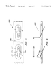
- the conventional gasket 40 shown in FIGS. 13 and 14 attempts to solve the problem of indefinite contact points inherent in a flat gasket surface by alternating downwardly projecting spring arms 42 and upwardly projecting spring arms 44 .
- this configuration requires that for a given length spring arm L, the distance between contact points D 1 on a component surface is about twice the length L.
- This design makes it difficult to maintain both a long spring arm, which has a long travel or tolerance for roughness or unevenness in a component surface, and a minimum small distance between adjacent contact points on the component surface adjacent the gasket 40 .
- this design requires two bending steps (one to form the upwardly projecting spring arms 44 and one to form the downwardly projecting the spring arms 42 ) to form the gasket 40 , making such a gasket difficult to manufacture.
- a gasket for mounting shielded electronics includes a body and a plurality of spring arms connected to the body.
- Each spring arm includes a free proximal portion, a free distal portion and a connection connecting the spring arm to the body.
- the free distal portion of each spring arm contacts a first component proximate to a first surface of the body.
- the free proximate portion of each spring arm contacts a second component proximate to an opposite second surface of the body.
- the distance between adjacent contacts on a component is less than or approximately equal to a predetermined ratio of a shielded radio wavelength.
- a method for mounting shielded electronics to a frame is disclosed.
- a gasket including a body and a plurality of spring arm portions are provided.
- Each spring arm includes a proximal portion, a distal portion and a connection connecting the spring arm to the body.
- a first component adjacent to a first surface of the body is contacted by the distal portion of each arm, and a second component adjacent to a second surface of the body is contacted by the proximal portion of each arm.
- the distal and proximal portions contact respective components such that the distance between adjacent contacts on a component is less than or approximately equal to a predetermined ratio of a shielded radio wavelength.
- the first component is secured to the second component.
- FIG. 1A is an schematic exploded perspective cut away view of a radio telephone including a prior art gasket
- FIG 1 B is an enlarged view of the area X in FIG. 1;
- FIG. 2 is an perspective view of a first embodiment of the present invention
- FIG. 3 is a top plan view of the embodiment shown in FIG. 1;
- FIG. 4 is a sectional view of the invention shown in FIGS. 2 and 3;
- FIG. 5 is a top plan view of a second embodiment of the present invention.
- FIG. 6 is a sectional view of the invention shown in FIG. 5;
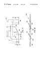
- FIG. 7 is a top plan view of a third embodiment of the present invention.
- FIG. 8 is a sectional side view of the device shown in FIG. 7;
- FIG. 9 is a top plan view of a first conventional device
- FIG. 10 is a side view of the device shown in FIG. 9;
- FIG. 11 is a top plan view of a second conventional device
- FIG. 12 is a side sectional view of the device shown in FIG. 11;
- FIG. 13 is a top plan view of a third conventional device.
- FIG. 14 is a side sectional view of the device shown in FIG. 13 .
- a gasket according to the present invention includes a plurality of spring arms which each include a proximal portion and a distal portion having contact areas projecting both below and above a plane defined by the gasket body.
- FIGS. 1A and 1B show a typical environment in which a gasket according to the present invention is used.
- a conventional gasket 50 is used to mount a printed circuit board (PCB) 52 to a shielding box or frame 54 in a radio telephone 56 .
- the gasket 50 includes a plurality (e.g., hundreds) of spring arms 58 which contact adjacent component surfaces.
- the gasket 50 is about 1 mm wide.
- the contact points on a component surface should be less than or approximately equal to a predetermined ratio (e.g., 1/20th) of the radio wavelength corresponding to the radio frequency signal to be shielded.
- a gasket 100 includes a body 102 and a plurality of spring arms 104 .
- Each spring arm 104 has asymmetrical proximal and distal portions 106 , 108 arranged on either side of a connection 110 which connects the spring arm 104 to the body of the gasket 100 .
- the connection 110 has a width W of, for example, about 0.2 mm. Both the distal portion 108 and the proximal portion 106 have corresponding free ends 114 , 112 .
- the distal free end 114 can project past a first surface 116 of the gasket body 102 while the proximal free end 112 projects past an opposite second surface 118 of the gasket body 102 .
- the distal portion 108 of the spring arm 104 has a length L 1 greater than the length L 2 of the proximal portion 106 of the spring arm 104 .
- L 1 can be about 1.6 mm and L 2 can be about 0.45 mm.
- the long distal portion 108 of the spring arm 104 has a long travel or tolerance 105 to ensure contact with an uneven or rough surface of a first component such as a PCB.
- the shorter proximal end 112 of each spring arm creates the desired defined contact points with the second component surface, such as a radio telephone frame.
- Each spring arm 104 is bent at the connection 110 so that the proximal and distal portions 106 , 108 of each spring arm 104 project out of the opposite surfaces 116 , 118 of the gasket body 102 . Because each spring arm 104 is asymmetrical around the connection 110 , the distance between distal ends 144 of adjacent spring arms of a particular length is less than the distance between distal ends of symmetrically configured spring arms. Therefore, long spring arms can contact adjacent components with relatively short distances between adjacent distal portions.
- the connection 110 contributes to the elasticity of the arm and has a torsional spring constant K 3 .
- the overall spring constant for each spring arm 104 is less than any one of the three other spring constants.
- a low spring constant is desirable because for a given compressing force, a spring arm will accommodate a range of movement in response to roughness or unevenness proportional to the spring constant.
- each spring arm 104 is formed to define a spring arm axis 120 at an angle with respect to edges 122 of the gasket body 102 in order to define a substantial portion of the gasket body 102 between adjacent spring arms.
- This configuration also allows one of the proximal or distal portions 106 , 108 to contact a component near the center of the gasket body 102 and the other portion to contact a component near an edge of the gasket body 102 .
- FIGS. 5 and 6 show a second embodiment of a gasket 130 according to the present invention where proximal and distal portions 132 , 134 of a spring arm 136 are symmetrical about connections 138 .
- the connections 138 connect the spring arm 136 to a body 140 of the gasket 130 .
- D 2 e.g., 2.5 mm
- the length L 3 of the proximal and distal portions 134 , 136 is smaller than the first embodiment because each distal portion is offset from adjacent distal portions by a proximal portion having the same length.
- the overall spring constant of each spring arm is more dependent on the torsional spring constant of the connections 138 , than is the spring arm of the first embodiment.
- FIGS. 7 and 8 show a third embodiment of a gasket 150 according to the present invention.
- the gasket 150 includes a double extension (or U-shaped) spring arm 152 attached to a gasket body 154 .
- the spring arm 152 includes free proximal and distal portions 156 , 158 .
- An extended connection 160 attaches the spring arm 152 to the gasket body.
- the extended connection 160 can have a width W 1 of about 0.2 mm and a length L 4 of about 0.5 mm.
- the length of the spring arm L 5 can be about 1.0 mm and the total width W 2 of the spring arm 152 can be about 0.6 mm.
- the elasticity of the spring arm 152 is more dependent on pure bending elasticity than torsional elasticity as compared to the other embodiments.
- the torsional spring constant between the spring arm 152 and connection 160 is not as significant to the overall spring constant as in the other embodiments.
- the gasket 150 can have a lower overall spring constant than comparable gaskets according to the other embodiments, and therefore be more tolerant of uneven component surfaces.
- the bending force is more evenly distributed through the spring arm 152 . As a result, the spring can withstand higher contact pressure without failing as compared to the other embodiments.
- a spring arm is thin (preferably about 0.05 mm) to achieve a low spring constant.
- a thin gasket body is difficult to assemble and mount. Therefore, in each of the embodiments according to the present invention, the spring arm is preferably thinner than the gasket body.
- the gasket is preferably about 1 mm wide.
- the gasket is formed of a metal material. More preferably, the gasket is formed of sheet metal such as stainless steel or spring steel. However, other elastic and electrically conductive materials can be used in accordance with the present invention.
- the gasket, according to the present invention can be stamped or etched according to conventional techniques.
- a gasket of the present invention can be used to mount shielded components in a radio telephone. Once a gasket is provided, a PCB is contacted with a distal portion of the spring arm, and the frame is contacted with a proximal portion of a spring arm. The PCB and frame are then secured to one another with the gasket arranged therebetween.
Abstract
Description

Claims (27)
Priority Applications (8)
| Application Number | Priority Date | Filing Date | Title |
|---|---|---|---|
| US09/399,157 US6332618B1 (en) | 1999-09-20 | 1999-09-20 | Double sided gasket |
| AT00962466T ATE238644T1 (en) | 1999-09-20 | 2000-09-11 | DOUBLE SIDED SEAL |
| AU74185/00A AU7418500A (en) | 1999-09-20 | 2000-09-11 | Double sided gasket |
| DE60002350T DE60002350D1 (en) | 1999-09-20 | 2000-09-11 | DOUBLE-SIDED SEAL |
| JP2001526018A JP2003510537A (en) | 1999-09-20 | 2000-09-11 | Double-sided gasket |
| EP00962466A EP1214870B1 (en) | 1999-09-20 | 2000-09-11 | Double sided gasket |
| CN00813038A CN1375180A (en) | 1999-09-20 | 2000-09-11 | Double sided gasket |
| PCT/EP2000/008835 WO2001022788A1 (en) | 1999-09-20 | 2000-09-11 | Double sided gasket |
Applications Claiming Priority (1)
| Application Number | Priority Date | Filing Date | Title |
|---|---|---|---|
| US09/399,157 US6332618B1 (en) | 1999-09-20 | 1999-09-20 | Double sided gasket |
Publications (1)
| Publication Number | Publication Date |
|---|---|
| US6332618B1 true US6332618B1 (en) | 2001-12-25 |
Family
ID=23578391
Family Applications (1)
| Application Number | Title | Priority Date | Filing Date |
|---|---|---|---|
| US09/399,157 Expired - Lifetime US6332618B1 (en) | 1999-09-20 | 1999-09-20 | Double sided gasket |
Country Status (8)
| Country | Link |
|---|---|
| US (1) | US6332618B1 (en) |
| EP (1) | EP1214870B1 (en) |
| JP (1) | JP2003510537A (en) |
| CN (1) | CN1375180A (en) |
| AT (1) | ATE238644T1 (en) |
| AU (1) | AU7418500A (en) |
| DE (1) | DE60002350D1 (en) |
| WO (1) | WO2001022788A1 (en) |
Cited By (8)
| Publication number | Priority date | Publication date | Assignee | Title |
|---|---|---|---|---|
| US20040196627A1 (en) * | 2001-06-27 | 2004-10-07 | Bertil Lohman | Housing for electronic circuits, electrically connecting element and contact spring, procedure for electromagnetic shielding |
| US20070011961A1 (en) * | 2005-06-24 | 2007-01-18 | Annes Jason L | Connector for sash window frame members |
| US20090207579A1 (en) * | 2008-02-15 | 2009-08-20 | Laird Technologies, Inc. | Emi shielding assemblies and related methods of retaining components thereof together |
| US20100093230A1 (en) * | 2007-01-31 | 2010-04-15 | Multi-Holding Ag | Contact element and use of such a contact element in a plug connection |
| US20110306252A1 (en) * | 2010-06-15 | 2011-12-15 | Research In Motion Limited | Spring finger grounding component and method of manufacture |
| DE102016213600B4 (en) | 2016-07-25 | 2019-03-14 | Audi Ag | Sealing element for fluid-tight and electrically conductive connection of a first component and a second component and corresponding component arrangement |
| US10253884B2 (en) * | 2014-09-04 | 2019-04-09 | Dana Automotive Systems Group, Llc | Gasket having upper and lower active layers and a spacer layer |
| DE102017131298A1 (en) * | 2017-12-24 | 2019-06-27 | Lisa Dräxlmaier GmbH | Cover for an electromagnetically shielded housing, electromagnetically shielded housing and method for producing an electromagnetically shielded housing |
Families Citing this family (2)
| Publication number | Priority date | Publication date | Assignee | Title |
|---|---|---|---|---|
| US9865939B2 (en) * | 2016-02-08 | 2018-01-09 | Microsoft Technology Licensing, Llc | Connecting element with a spring tab |
| US10123466B2 (en) | 2017-03-31 | 2018-11-06 | Raytheon Company | Electrically and thermally conductive planar interface gasket with deformable fingers |
Citations (15)
| Publication number | Priority date | Publication date | Assignee | Title |
|---|---|---|---|---|
| US2707012A (en) * | 1953-01-07 | 1955-04-26 | Illinois Tool Works | Lock washer |
| FR2078686A5 (en) | 1970-02-26 | 1971-11-05 | Siemens Ag | |
| US3826583A (en) * | 1972-11-09 | 1974-07-30 | Pare R Lee | Leaf spring pavement joint seal |
| DE2348686A1 (en) | 1973-09-27 | 1975-04-03 | Siemens Ag | Contact plates for microwave assemblies - have fastening element consisting of plastics pin with square shank |
| DE2448421B1 (en) | 1974-10-10 | 1975-06-05 | Siemens Ag | Band-shaped metallic seal for the high-frequency-tight connection of detachable metallic shielding elements |
| US4055208A (en) * | 1976-09-20 | 1977-10-25 | Illinois Tool Works Inc. | Locking fastener device |
| US5204496A (en) * | 1992-04-01 | 1993-04-20 | Digital Equipment Corporation | EMI shielding gasket |
| US5409200A (en) * | 1992-03-05 | 1995-04-25 | Zingher; Arthur R. | Printed-circuit-like array of springs with non-linear force vs deflection |
| US5534662A (en) * | 1994-08-31 | 1996-07-09 | International Business Machines Corporation | Chassis mounted electromagnetic interference grounding assembly for electronic modules |
| US5682299A (en) * | 1995-06-06 | 1997-10-28 | Norand Corporation | PCMCIA module having multiple point grounding |
| US5825634A (en) * | 1995-12-22 | 1998-10-20 | Bfgoodrich Avionics Systems, Inc. | Circuit board having an EMI shielded area |
| US5917147A (en) * | 1996-01-30 | 1999-06-29 | Digital Equipment Corporation | Clip-on non-snag grounding finger array |
| WO1999033328A1 (en) | 1997-12-19 | 1999-07-01 | Siemens Medical Systems | Surface mount spring gasket and emi enclosure |
| DE29906262U1 (en) | 1999-04-08 | 1999-07-15 | Hermann Stahl Gmbh | Spring element |
| US5957465A (en) * | 1997-06-17 | 1999-09-28 | Sun Microsystems, Inc. | Modular EMC PCI card gasket |
-
1999
- 1999-09-20 US US09/399,157 patent/US6332618B1/en not_active Expired - Lifetime
-
2000
- 2000-09-11 WO PCT/EP2000/008835 patent/WO2001022788A1/en active IP Right Grant
- 2000-09-11 AU AU74185/00A patent/AU7418500A/en not_active Abandoned
- 2000-09-11 CN CN00813038A patent/CN1375180A/en active Pending
- 2000-09-11 EP EP00962466A patent/EP1214870B1/en not_active Expired - Lifetime
- 2000-09-11 JP JP2001526018A patent/JP2003510537A/en not_active Withdrawn
- 2000-09-11 AT AT00962466T patent/ATE238644T1/en not_active IP Right Cessation
- 2000-09-11 DE DE60002350T patent/DE60002350D1/en not_active Expired - Lifetime
Patent Citations (17)
| Publication number | Priority date | Publication date | Assignee | Title |
|---|---|---|---|---|
| US2707012A (en) * | 1953-01-07 | 1955-04-26 | Illinois Tool Works | Lock washer |
| FR2078686A5 (en) | 1970-02-26 | 1971-11-05 | Siemens Ag | |
| GB1321140A (en) | 1970-02-26 | 1973-06-20 | Siemens Ag | Electrical screening assemblies |
| US3826583A (en) * | 1972-11-09 | 1974-07-30 | Pare R Lee | Leaf spring pavement joint seal |
| DE2348686A1 (en) | 1973-09-27 | 1975-04-03 | Siemens Ag | Contact plates for microwave assemblies - have fastening element consisting of plastics pin with square shank |
| DE2448421B1 (en) | 1974-10-10 | 1975-06-05 | Siemens Ag | Band-shaped metallic seal for the high-frequency-tight connection of detachable metallic shielding elements |
| US4061413A (en) | 1974-10-10 | 1977-12-06 | Siemens Aktiengesellschaft | Gasket for the high-frequency-tight connection of detachable metallic shielding elements |
| US4055208A (en) * | 1976-09-20 | 1977-10-25 | Illinois Tool Works Inc. | Locking fastener device |
| US5409200A (en) * | 1992-03-05 | 1995-04-25 | Zingher; Arthur R. | Printed-circuit-like array of springs with non-linear force vs deflection |
| US5204496A (en) * | 1992-04-01 | 1993-04-20 | Digital Equipment Corporation | EMI shielding gasket |
| US5534662A (en) * | 1994-08-31 | 1996-07-09 | International Business Machines Corporation | Chassis mounted electromagnetic interference grounding assembly for electronic modules |
| US5682299A (en) * | 1995-06-06 | 1997-10-28 | Norand Corporation | PCMCIA module having multiple point grounding |
| US5825634A (en) * | 1995-12-22 | 1998-10-20 | Bfgoodrich Avionics Systems, Inc. | Circuit board having an EMI shielded area |
| US5917147A (en) * | 1996-01-30 | 1999-06-29 | Digital Equipment Corporation | Clip-on non-snag grounding finger array |
| US5957465A (en) * | 1997-06-17 | 1999-09-28 | Sun Microsystems, Inc. | Modular EMC PCI card gasket |
| WO1999033328A1 (en) | 1997-12-19 | 1999-07-01 | Siemens Medical Systems | Surface mount spring gasket and emi enclosure |
| DE29906262U1 (en) | 1999-04-08 | 1999-07-15 | Hermann Stahl Gmbh | Spring element |
Cited By (13)
| Publication number | Priority date | Publication date | Assignee | Title |
|---|---|---|---|---|
| US20040196627A1 (en) * | 2001-06-27 | 2004-10-07 | Bertil Lohman | Housing for electronic circuits, electrically connecting element and contact spring, procedure for electromagnetic shielding |
| US7158388B2 (en) * | 2001-06-27 | 2007-01-02 | Bertil Lohman Design Ab | Housing for electronic circuits, electrically connecting element and contact spring, procedure for electromagnetic shielding |
| US20070011961A1 (en) * | 2005-06-24 | 2007-01-18 | Annes Jason L | Connector for sash window frame members |
| US7628562B2 (en) * | 2005-06-24 | 2009-12-08 | Newell Operating Company | Connector for sash window frame members |
| US8057269B2 (en) * | 2007-01-31 | 2011-11-15 | Multi-Holding Ag | Contact element and use of such a contact element in a plug connection |
| US20100093230A1 (en) * | 2007-01-31 | 2010-04-15 | Multi-Holding Ag | Contact element and use of such a contact element in a plug connection |
| US7889515B2 (en) * | 2008-02-15 | 2011-02-15 | Laird Technologies, Inc. | EMI shielding assemblies and related methods of retaining components thereof together |
| US20090207579A1 (en) * | 2008-02-15 | 2009-08-20 | Laird Technologies, Inc. | Emi shielding assemblies and related methods of retaining components thereof together |
| US20110306252A1 (en) * | 2010-06-15 | 2011-12-15 | Research In Motion Limited | Spring finger grounding component and method of manufacture |
| US10253884B2 (en) * | 2014-09-04 | 2019-04-09 | Dana Automotive Systems Group, Llc | Gasket having upper and lower active layers and a spacer layer |
| DE102016213600B4 (en) | 2016-07-25 | 2019-03-14 | Audi Ag | Sealing element for fluid-tight and electrically conductive connection of a first component and a second component and corresponding component arrangement |
| US11022219B2 (en) * | 2016-07-25 | 2021-06-01 | Audi Ag | Seal element for connecting a first component and a second component in a fluid-tight and electrically conductive manner, and corresponding component assembly |
| DE102017131298A1 (en) * | 2017-12-24 | 2019-06-27 | Lisa Dräxlmaier GmbH | Cover for an electromagnetically shielded housing, electromagnetically shielded housing and method for producing an electromagnetically shielded housing |
Also Published As
| Publication number | Publication date |
|---|---|
| EP1214870A1 (en) | 2002-06-19 |
| CN1375180A (en) | 2002-10-16 |
| WO2001022788A1 (en) | 2001-03-29 |
| DE60002350D1 (en) | 2003-05-28 |
| AU7418500A (en) | 2001-04-24 |
| EP1214870B1 (en) | 2003-04-23 |
| ATE238644T1 (en) | 2003-05-15 |
| JP2003510537A (en) | 2003-03-18 |
Similar Documents
| Publication | Publication Date | Title |
|---|---|---|
| US7374430B2 (en) | Electrical connector for connecting a flat-type circuit board | |
| US6538197B1 (en) | Conductive member | |
| EP1264523B1 (en) | Shielding gasket | |
| US7052320B2 (en) | Electrical connector having shielding plates | |
| US6332618B1 (en) | Double sided gasket | |
| KR970005577B1 (en) | Electrically-conductive elastomeric connector | |
| JPH07335295A (en) | Circuit card device and ground clip that is used for it | |
| CN102972105B (en) | Surface mount clip | |
| TWI571016B (en) | Connector | |
| WO2006055067A1 (en) | Low profile circuit board connector | |
| EP3414798B1 (en) | Connecting element with a spring tab | |
| JP2003031984A (en) | Gasket for electromagnetic shield | |
| US6916187B2 (en) | Ground connection structure, ground connecting member and ground connection method | |
| US6046530A (en) | Piezoelectric resonance component | |
| JP4576096B2 (en) | Electrical connector | |
| JP2010021213A (en) | Shielding case and high-frequency device | |
| KR100238186B1 (en) | Emc gasket apparatus | |
| US6714423B1 (en) | Protecting device against electromagnetic radiation comprising EMI-gaskets | |
| EP1231827A1 (en) | Gasket with bend projections and method of manufacturing the same | |
| JPH0650035U (en) | Matrix type liquid crystal display device | |
| CN111370886B (en) | Elastic connection device and electronic equipment | |
| CN111211452B (en) | Electronic device | |
| JPH0642391Y2 (en) | Shield frame | |
| JPH026644Y2 (en) | ||
| JPH08203626A (en) | Connector for flexible conducting member |
Legal Events
| Date | Code | Title | Description |
|---|---|---|---|
| AS | Assignment |
Owner name: TELEFONAKTIEBOLAGET LM ERICSSON, SWEDEN Free format text: ASSIGNMENT OF ASSIGNORS INTEREST;ASSIGNOR:KARLSSON, PETER;REEL/FRAME:010382/0423 Effective date: 19991104 |
|
| STCF | Information on status: patent grant |
Free format text: PATENTED CASE |
|
| FEPP | Fee payment procedure |
Free format text: PAYOR NUMBER ASSIGNED (ORIGINAL EVENT CODE: ASPN); ENTITY STATUS OF PATENT OWNER: LARGE ENTITY |
|
| FPAY | Fee payment |
Year of fee payment: 4 |
|
| FPAY | Fee payment |
Year of fee payment: 8 |
|
| FPAY | Fee payment |
Year of fee payment: 12 |
|
| AS | Assignment |
Owner name: HIGHBRIDGE PRINCIPAL STRATEGIES, LLC, AS COLLATERA Free format text: LIEN;ASSIGNOR:OPTIS WIRELESS TECHNOLOGY, LLC;REEL/FRAME:032180/0115 Effective date: 20140116 |
|
| AS | Assignment |
Owner name: OPTIS WIRELESS TECHNOLOGY, LLC, TEXAS Free format text: ASSIGNMENT OF ASSIGNORS INTEREST;ASSIGNOR:CLUSTER, LLC;REEL/FRAME:032286/0501 Effective date: 20140116 Owner name: CLUSTER, LLC, DELAWARE Free format text: ASSIGNMENT OF ASSIGNORS INTEREST;ASSIGNOR:TELEFONAKTIEBOLAGET L M ERICSSON (PUBL);REEL/FRAME:032285/0421 Effective date: 20140116 |
|
| AS | Assignment |
Owner name: WILMINGTON TRUST, NATIONAL ASSOCIATION, MINNESOTA Free format text: SECURITY INTEREST;ASSIGNOR:OPTIS WIRELESS TECHNOLOGY, LLC;REEL/FRAME:032437/0638 Effective date: 20140116 |
|
| AS | Assignment |
Owner name: OPTIS WIRELESS TECHNOLOGY, LLC, TEXAS Free format text: RELEASE BY SECURED PARTY;ASSIGNOR:HPS INVESTMENT PARTNERS, LLC;REEL/FRAME:039361/0001 Effective date: 20160711 |