US6335977B1 - Action recognizing apparatus and recording medium in that action recognizing program is recorded - Google Patents
Action recognizing apparatus and recording medium in that action recognizing program is recorded Download PDFInfo
- Publication number
- US6335977B1 US6335977B1 US09/084,950 US8495098A US6335977B1 US 6335977 B1 US6335977 B1 US 6335977B1 US 8495098 A US8495098 A US 8495098A US 6335977 B1 US6335977 B1 US 6335977B1
- Authority
- US
- United States
- Prior art keywords
- motion
- dimensional
- imaged object
- magnitude
- unit
- Prior art date
- Legal status (The legal status is an assumption and is not a legal conclusion. Google has not performed a legal analysis and makes no representation as to the accuracy of the status listed.)
- Expired - Fee Related
Links
Images


Classifications
-
- G—PHYSICS
- G06—COMPUTING; CALCULATING OR COUNTING
- G06T—IMAGE DATA PROCESSING OR GENERATION, IN GENERAL
- G06T7/00—Image analysis
- G06T7/20—Analysis of motion
-
- G—PHYSICS
- G06—COMPUTING; CALCULATING OR COUNTING
- G06V—IMAGE OR VIDEO RECOGNITION OR UNDERSTANDING
- G06V40/00—Recognition of biometric, human-related or animal-related patterns in image or video data
- G06V40/20—Movements or behaviour, e.g. gesture recognition
-
- A—HUMAN NECESSITIES
- A63—SPORTS; GAMES; AMUSEMENTS
- A63F—CARD, BOARD, OR ROULETTE GAMES; INDOOR GAMES USING SMALL MOVING PLAYING BODIES; VIDEO GAMES; GAMES NOT OTHERWISE PROVIDED FOR
- A63F2300/00—Features of games using an electronically generated display having two or more dimensions, e.g. on a television screen, showing representations related to the game
- A63F2300/10—Features of games using an electronically generated display having two or more dimensions, e.g. on a television screen, showing representations related to the game characterized by input arrangements for converting player-generated signals into game device control signals
- A63F2300/1087—Features of games using an electronically generated display having two or more dimensions, e.g. on a television screen, showing representations related to the game characterized by input arrangements for converting player-generated signals into game device control signals comprising photodetecting means, e.g. a camera
- A63F2300/1093—Features of games using an electronically generated display having two or more dimensions, e.g. on a television screen, showing representations related to the game characterized by input arrangements for converting player-generated signals into game device control signals comprising photodetecting means, e.g. a camera using visible light
-
- A—HUMAN NECESSITIES
- A63—SPORTS; GAMES; AMUSEMENTS
- A63F—CARD, BOARD, OR ROULETTE GAMES; INDOOR GAMES USING SMALL MOVING PLAYING BODIES; VIDEO GAMES; GAMES NOT OTHERWISE PROVIDED FOR
- A63F2300/00—Features of games using an electronically generated display having two or more dimensions, e.g. on a television screen, showing representations related to the game
- A63F2300/80—Features of games using an electronically generated display having two or more dimensions, e.g. on a television screen, showing representations related to the game specially adapted for executing a specific type of game
- A63F2300/8029—Fighting without shooting
Definitions
- the present invention is related to an action recognizing apparatus for imaging motion of a human and the like, for specifying motion of this imaged object from an acquired image with respect to each of the portions thereof, and for reproducing the motion of the imaged object based on the specified motion, and also related to a recording medium in which a motion recognizing program is recorded.
- a gesture of a human is imaged by an image sensor such as a CCD
- the imaged gesture is reflected by motion of a person expressed by computer graphics, and then the original gesture is reproduced on a computer screen.
- One optical motion capture is described in the publication titled “Imidas '97” at pages 846 to 847.
- light reflection markers are attached to respective portions of the human body as the imaged object. The motion of these portions is imaged by a camera along different directions, the three-dimensional positions of the light reflection markers at respective time instants are detected by processing the acquired images, and then three-dimensional data about the motion of the hands and the feet are calculated based on the three-dimensional positions.
- the original motion of the human can be reproduced on a human model expressed by the computer graphics employing these three-dimensional data.
- the above-described conventional action recognizing system has the following problems. That is, it is very difficult to attach the light reflection markers specifying the respective portions of the human body onto the respective portions of the human body. Motion of an animal, such as a monkey, other than a human cannot be easily reproduced in accordance with this conventional action recognizing system because it is very difficult to attach the light reflection markers to the animal. There is another problem in that the application range of this conventional action recognizing system is limited.
- the present invention has been made to solve the above-described problem, and, therefore, has an object of providing action recognizing apparatus reproducing motion of an imaged object, such as a human, in real time by analyzing motion of an image produced by imaging the motion of the imaged object without employing an auxiliary means, such as a light reflection marker. Also, another object of the present invention is to provide a recording medium in which an action recognizing program is recorded.
- An action recognizing apparatus comprises an image input unit for forming an image containing motion of an imaged object at a plurality of imaging angles with a plurality of image sensors to acquire a plurality of two-dimensional images; a two-dimensional motion detecting unit for calculating a direction and magnitude of motion of each of pixels within each of the two-dimensional images formed by the image input unit; a region specifying unit for specifying a region having a magnitude of motion larger than or equal to a predetermined magnitude, the motion magnitude being calculated by the two-dimensional motion detecting unit; a three-dimensional motion detecting unit for positioning the specific region specified by the region specifying unit with respect to the plurality of two-dimensional images, whereby a three-dimensional position of the specific region and three-dimensional motion of the specific region are calculated; a portion predicting unit for predicting that the three-dimensional motion of the specific region calculated by the three-dimensional motion detecting unit corresponds to any of the portions of the imaging object; and an action reproducing unit for moving a model in
- the region specifying unit in the action recognizing apparatus subdivides a two-dimensional image into a plurality of scanning ranges which overlap with each other; scans each of the scanning ranges to select as a subject region a region having a maximum averaged value of motion magnitude of the respective pixels; and furthermore establishes a region where the averaged value is larger than a predetermined value as the specific region.
- the action reproducing unit in the action recognizing apparatus reproduces the motion of the imaging object by way of motion of a model expressed by computer graphics.
- the action reproducing unit in the action recognizing apparatus reproduces the motion of the imaging object by way of motion of an automatic control machine.
- the action reproducing unit in the action recognizing apparatus includes a second model, different from the model used to reproduce the motion of the imaged object, whereby a mutual effect between the motion of the imaging operation and the motion of the second model is realized in a simulation.
- an action recognizing program causes a computer to calculate a direction and magnitude of motion of each of pixels within two-dimensional images formed at a plurality of imaging angles; specify a region having calculated motion magnitude larger than or equal to a predetermined magnitude; position the specified specific region with respect to the plurality of two-dimensional images, whereby a three-dimensional position of the specific region and three-dimensional motion of the specific region are calculated; predict the three-dimensional motion of the calculated specific region corresponding to any of the portions of the imaged object; and move a model in a simulation based on the motion with respect to each of the predicted portions, whereby motion of the imaging object is reproduced on the model.
- FIG. 1 is a block diagram showing an arrangement of an action recognizing apparatus according to an embodiment 1 of the present invention
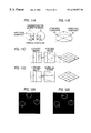
- FIG. 2 is an illustration representing an example of the action recognizing apparatus according to the embodiment 1 of the present invention.
- FIG. 3 is a diagram indicating a projection relationship and explaining that when a human to be imaged is located within intersecting imaging ranges of two image sensors, the image is projected onto a projection plane, according to embodiment 1 of the present invention
- FIGS. 4A to 4 D are diagrams showing motion of the respective portions of a human captured in each of four levels when the intersecting imaging ranges of the two image sensors are subdivided into the four levels based on height, according to embodiment 1 of the present invention
- FIGS. 5A and 5B are illustrations indicating image data of the two image sensors according to embodiment 1 of the present invention.
- FIGS. 6A and 6B are illustrations showing an optical flow and three specific regions which are acquired from images formed by the respective image sensors, according to embodiment 1 of the present invention.
- FIGS. 7A to 7 D are explanatory diagrams explaining operation of a region specifying unit according to embodiment 1 of the present invention.
- FIG. 8 is a diagram indicating nine scanning regions of the region specifying unit according to embodiment 1 of the present invention.
- FIG. 9 is a flow chart explaining a specific region determining algorithm by the region specifying unit according to embodiment 1 ;
- FIG. 10 is an explanatory diagram explaining operation of a three-dimensional motion detecting unit according to embodiment 1 of the present invention.
- FIGS. 11A to 11 D are explanatory diagrams explaining operation of a three-dimensional motion detecting unit according to embodiment 1 of the present invention.
- FIGS. 12A and 12B are illustrations showing three specific regions and an averaged vector of each of these specific regions which are acquired from the images obtained from the respective image sensors according to embodiment 1 of the present invention
- FIGS. 13A and 13B are illustrations representing a horizontal component and a vertical component of a motion vector within a three-dimensional space predicted at vertical positions where an identification pair is present in accordance with embodiment 1 of the present invention.
- FIG. 14 is a diagram indicating an arrangement of an image input unit according to embodiment 1 of the present invention including three image sensors.
- FIG. 1 is a schematic block diagram of an action recognizing apparatus according to embodiment 1 of the present invention.
- This action recognizing apparatus includes six units, namely, an image input unit 1 , a two-dimensional motion detecting unit 2 , a region specifying unit 3 , a three-dimensional motion detecting unit 4 , a portion predicting unit 5 , and an action reproducing unit 6 .
- the image input unit 1 includes a plurality of image sensors for forming images of motion of an object at different angles. This embodiment 1 illustrates the image input unit 1 as including two image sensors.
- the two-dimensional motion detecting unit 2 calculates two-dimensional motion from an optical flow with respect to images sequentially output from the respective image sensors of the image input unit 1 .
- the direction and magnitude of motion for every pixel of each image are calculated based upon temporal and spatial changes in brightness of the respective pixels.
- the region specifying unit 3 specifies a region having significant motion from the optical flow detected by the two-dimensional motion detecting unit 2 , and calculates a direction and magnitude of two-dimensional motion of the entire region. Concretely speaking, the direction and magnitude of the two-dimensional motion are calculated based upon a vector average value of the optical flows of the respective regions.
- the three-dimensional motion detecting unit 4 calculates three-dimensional motion involving depth in correspondence with the region specified by the region specifying unit 3 while using the differences in the imaging angles of the respective image sensors employed in the image input unit 1 .
- the portion predicting unit 5 predicts whether the region detected by the three-dimensional motion detecting unit 4 corresponds to motion of respective portions of a human.
- the action reproducing unit 6 moves a human model expressed by computer graphics based on the motion of the portion predicted by the portion predicting unit 5 .
- FIG. 2 is an illustration of an example for moving a human model in a simulation using the action recognizing apparatus according to this embodiment 1, and represents a positional relationship between a human 18 functioning as an imaged subject and image sensors 7 and 8 .
- the human 18 moves respective portions of his body, such as his head, his hands, and his feet, along directions indicated by arrows 10 , so that a human model 13 represented on a screen of a CRT monitor 12 connected to a computer 11 is moved in real time.
- FIG. 3 illustratively shows how the motion of the human 18 within an intersecting imaging range 19 of the image sensors 7 and 8 is projected on each of imaging planes 14 and 15 of the image sensors 7 and 8 .
- the motions 10 of the respective portions are projected as arrows 16 on the imaging plane 14 , and projected as arrows 17 on the imaging plane 15 .
- FIGS. 4A to 4 D represent the motion 10 of a moving portion and a horizontal position of this moving portion when the intersecting imaging range 19 is subdivided into four levels, depending upon height, and the moving portion is present in a horizontal plane of each level. Furthermore, FIGS. 4A-4D indicate how the motion 10 of the respective portions is projected onto the imaging planes 14 and 15 with respect to each of the levels. FIG. 4A to FIG. 4D represent motion 16 and motion 17 when the motion 10 of the head, right hand, left hand, and left foot are respectively projected on the imaging planes 14 and 15 at the respective levels. While using this motion projection relationship, it is possible to predict three-dimensional motion involving a depth direction from the two-dimensional motion in the respective imaging planes.
- the two-dimensional motion indicated by the optical flow and the like is calculated from the output image from the image sensors 7 and 8 with respect to each of the imaging planes.
- the two-dimensional motions calculated with respect to each of the imaging planes a region having significant motion is identified.
- the three-dimensional motion involving the depth direction can be predicted from the two-dimensional motion in these regions and the positions of these regions.
- FIGS. 5A and 5B represent an example of image data outputted from two sets of image sensors installed at different imaging angles relative to an imaged object.
- FIGS. 6A and 6B show optical flows with respect to the respective output images.
- a white circle shown in FIGS. 6A and 6B represents a specific region having significant motion and identified by the region specifying unit 3 .
- Japanese Patent Publication 4-241079 describes a method employing a neural network. In this calculating method, the velocity vectors (motion vectors) of the respective pixels are acquired from the temporal and spatial changes in the brightness of the respective pixels in the two-dimensional image, and then the direction of the motion and the magnitude thereof are calculated with respect to each of the pixels.
- the optical flow calculating method other calculating methods than the above-explained optical flow calculating method may be employed.
- FIGS. 7A to 7 D and FIG. 8 a description is given of how to detect the specific region indicated by the white circle using the region specifying unit 3 from the acquired optical flow. At the same time, a description is given of a corresponding relationship between these drawings and process operations defined at steps S 1 to S 3 of a flow chart for explaining a detection algorithm shown in FIG. 9 .
- FIG. 7A represents an example of an optical flow calculated in the two-dimensional motion detecting unit 2 .
- nine subject regions are detected by the region specifying unit 3 (step S 1 ).
- Each of these nine subject regions is selected from sixteen scanning ranges which mutually overlap, as indicated in FIG. 8 . That is, a circular region having a constant radius is scanned within a scanning range for a maximum of an averaged value of motion vectors (referred to as an “averaged vector” hereinafter).
- a subject region having a value smaller than or equal to a preset threshold value is deleted (step S 2 , namely, the hatched subject regions of FIG. 7C are deleted).
- a subject region is deleted if it overlaps another subject region and has a smaller averaged vector (step S 3 , namely, the hatched subject regions of FIG. 7D are deleted).
- step S 3 namely, the hatched subject regions of FIG. 7D are deleted.
- the three-dimensional motion detecting unit 4 first selects one specific region on an L side and another specific region on an R side as an identification pair, in which a difference between an upper position and a lower position is smaller than or equal to a threshold value, as specific regions acquired at different imaging angles (referred to as an “L side” and a “R side” hereinafter).
- an identification pair positions along right and left directions and a depth direction are predicted from horizontal positions on the L side and the R side.
- FIG. 11A averaged vectors of the specific regions on the L side and the R side, functioning as the identification pair, are subdivided into a horizontal direction component and a vertical direction component. Then, as shown in FIG.
- the horizontal direction components of both the specific regions are vector-synthesized with each other to produce a motion vector involving the right and left directions and the depth direction. It should also be understood that the vertical direction component directly constitutes a motion vector in the vertical direction within a three-dimensional space.
- FIGS. 12A and 12B correspond to the specific regions denoted by the white circles, and the averaged vectors of the motion vectors indicated by the white arrows shown in FIGS. 6A and 6B, respectively.
- the three-dimensional motion detecting unit 4 Based on the positions of the specific regions from respective different imaging angles and the two-dimensional motions of these specific regions, the three-dimensional motion detecting unit 4 outputs results such as illustrated in FIGS. 13A and 13B.
- FIG. 13A represents predicted positions (circular symbols) along either the depth direction or the right and left directions, and motion (arrow symbols) along the horizontal direction at the upper and lower positions where the identification pairs of the L-sided specific region and the R-sided specific region are located.
- FIG. 13B shows motion (arrow symbols) of each of the identification pair along the vertical direction.
- the portion predicting unit 5 predicts that the three-dimensional motion acquired by the three-dimensional motion detecting unit 4 with respect to each of the specific regions corresponds to motion of a human. For instance, assuming the below-mentioned restriction condition, the portion predicting unit 5 can predict whether the motion of the specific region is equal to the motion of a specific portion of the human.
- this restriction condition for instance, as to the four levels shown in FIGS. 13A and 13B, the uppermost level is allocated to a range where the head of the human moves, the second and third levels are allocated to a range where the right and left hands move, and the lowermost level is allocated to a range where the right and left feet move.
- both the right hand and the right foot are allocated to the right half portions of the respective levels, whereas both the left hand and the left foot are allocated to the left half portions as an initial condition.
- the portion prediction is realized when the right and left hands intersect with the right and left feet by tracing changes in the positions of the specific regions detected at respective temporal levels.
- the action reproducing unit 6 moves a human model based on the motion of respective body portions, such as the head, the right and left hand, and the right and left feet, predicted by the portion predicting unit 5 .
- a human model described in “Proceedings of SIGGRAPH '95”, titled “Fourier Principles for Emotion-based Human Figure Animation” (pages 91 to 96).
- the motion of the respective body portions of the human is expressed based on the motion along the three (x, y, z) directions related to nineteen joints of the hands, feet, and body of the human.
- the motion of the respective body portions predicted by the portion predicting unit 5 is applied as the input information to the action reproducing unit 6 .
- motion of a tip of a hand may be converted into rotation angles (namely, rotation angles around the x-axis, the y-axis, and the z-axis) of an elbow and of a shoulder.
- the motion may be converted into rotation angles of respective joints required to produce changes in positions in conjunction with the motion of these portions.
- motion of the respective joints of the human model along the three directions may be acquired based on these rotation angles.
- the human model expressed by computer graphics may be moved in accordance with the gestures of the human.
- the above-explained action recognizing calculation for the imaged object can be realized by an action recognizing program, and this action recognizing program is recorded on a recording medium.
- the two-dimensional motion of this image can be correctly acquired.
- the acquired two-dimensional motion need not be corrected off line, but the motion of a human and the like can be reproduced in real time.
- the motion of the imaged object has been reproduced on the model in real time.
- the corrected motion may be transmitted to the model.
- the image input unit 1 includes two image sensors 7 and 8 .
- the image input unit may include three image sensors 7 to 9 , as indicated in FIG. 14 .
- Four or more image sensors may be employed.
- the motion of the imaged object may be reproduced by, for instance, motion of an automatic control machine, such as a robot, other than the computer graphic representation.
- information related to the motion of the respective body portions of a human which has been acquired in this embodiment, may be transmitted by radio signals to a robot.
- rotations of respective joints of the robot such as the elbow, the knee, the neck, and the shoulder, may be controlled.
- a single receiver apparatus mounted on the robot may receive the motion information radio signal and may transmit a control signal to the respective joints.
- receiver apparatus may be mounted on the respective joints to receive the control signals.
- dangerous work may be executed by the robot instead of a human who cannot enter dangerous areas involving such dangerous work.
- the motion information for the reproduced imaged object may be transmitted to a game machine and the like, so that a game operation may be performed without employing an interface such as a joy stick.
- the action reproducing unit 6 has a single model for reproducing the motion of the imaged object.
- another model into which detailed motion of a wrist and a joint has been previously entered may be alternatively usdt, and a mutual effect between this second model and the model described above for reproducing the motion of the imaged object may be realized in a simulation.
- Such an alternative example will now be represented.
- the game players are required to manipulate the characters properly in order to avoid stumbling of the characters.
- the game players may have virtual experiences of the mutual effects between the counter parties and the characters of the game players by observing the mutual effects between the characters in such sport combative games. If the action recognizing apparatus according to this embodiment is employed in such a sport combative game, then the game manipulation may be replaced by the action of the game player himself. As a result, realistic feelings of the mutual effects between the game character and the game player may be increased. In other words, the game player himself may train his instantaneous power to attacking and defending actions, so that the game player may train the character in a simulation.
- the action recognizing apparatus of the first arrangement of the present invention includes an image input unit for forming an image including motion of an imaged object at a plurality of imaging angles with a plurality of image sensors to acquire a plurality of two-dimensional images; a two-dimensional motion detecting unit for calculating direction and magnitude of motion of each pixel within each of the two-dimensional images of the image input unit; a region specifying unit for specifying a region having a movement larger than or equal to a threshold movement, the motion magnitude being calculated by the two-dimensional motion detecting unit; a three-dimensional motion detecting unit for detecting the position of the region specified by the region specifying unit with respect to the plurality of two-dimensional images, whereby a three-dimensional position of the specific region and three-dimensional motion of the specific region are calculated; a portion predicting unit for predicting whether the three-dimensional motion of the specific region calculated by the three-dimensional motion detecting unit corresponds to any of the portions of the imaged object; and an action reproducing unit for moving a model in a simulation
- the motion of the imaged object under various conditions can be reproduced on the model without requiring an auxiliary means such as light reflection markers. Also, since the direction and the magnitude of the motion of the acquired image with respect to each of the pixels are directly calculated, the two-dimensional motion of this image can be correctly acquired. As a consequence, the acquired two-dimensional motion need not be corrected off line, but the motion of a human can be reproduced in real time.
- the region specifying unit subdivides a two-dimensional image into a plurality of scanning ranges which overlap with each other; scans each of the scanning ranges to select as a subject region a region having a maximum averaged motion magnitude of the respective pixels; and selects a region in which the averaged motion magnitude is larger than or equal to a predetermined value as the specific region.
- the action reproducing unit reproduces the motion of the imaged object by motion of a model expressed by computer graphics.
- the motion of a human under various conditions can be reproduced by computer graphics in real time without requiring auxiliary means such as light reflection markers.
- the action reproducing unit reproduces the motion of the imaged object in the motion of an automatic control machine. Therefore, dangerous work within an area where no human is allowed to enter can be executed by a robot instead of a human.
- the action reproducing unit includes another model, different from the model used to reproduce the motion of the imaged object, whereby a mutual effect between the motion of the imaging operation and the motion of the another model is realized in a simulation.
- a mutual effect between the motion of the imaging operation and the motion of the another model is realized in a simulation.
- an action recognizing program causes a computer to calculate a direction and magnitude of motion of each of pixels within two-dimensional images imaged at a plurality of imaging angles; specify a region having a calculated motion magnitude larger than or equal to a predetermined magnitude; position the region with respect to the plurality of two-dimensional images, whereby a three-dimensional position of the region and three-dimensional motion of the region are calculated; predict the three-dimensional motion of the calculated region to correspond to any of the portions of the imaged object; and move a model in a simulation based on the motion with respect to each of the predicted portions, whereby motion of the imaged object is reproduced on the model.
- the motion of the imaged object can be reproduced on the model in real time.
Abstract
Motion of a human under various conditions is reproduced by a computer graphics and the like in a real time manner without using auxiliary means such as a light reflection marker. An action recognizing apparatus is arranged by an image input unit 1 for imaging an image containing motion of an imaging object at a plurality of imaging angles by a plurality of image sensors to thereby acquire a plurality of two-dimensional images; a two-dimensional motion detecting unit 2 for calculating a direction of motion and strength thereof of each of pixels within each of the two-dimensional images imaged, a region specifying unit 3 for specifying such a region having strength of the calculated motion larger than, or equal to a predetermined strength value; a three-dimensional motion detecting unit 4 for positioning the specific region specified with respect to the plurality of two-dimensional images, whereby a three-dimensional position of the specific region and three-dimensional motion of the specific region are calculated; a portion predicting unit 5 for predicting that the calculated three-dimensional motion corresponds to any of the portions of the imaging object; and an action reproducing unit 6 for moving a model in a simulation manner based the motion predicted by the portion predicting unit 5 with respect to each of the portions, whereby motion of the imaging object is reproduced on the model.
Description
The present invention is related to an action recognizing apparatus for imaging motion of a human and the like, for specifying motion of this imaged object from an acquired image with respect to each of the portions thereof, and for reproducing the motion of the imaged object based on the specified motion, and also related to a recording medium in which a motion recognizing program is recorded.
As the conventional technique in which a gesture of a human is imaged by an image sensor such as a CCD, the imaged gesture is reflected by motion of a person expressed by computer graphics, and then the original gesture is reproduced on a computer screen. One optical motion capture is described in the publication titled “Imidas '97” at pages 846 to 847. In this optical motion capture, light reflection markers are attached to respective portions of the human body as the imaged object. The motion of these portions is imaged by a camera along different directions, the three-dimensional positions of the light reflection markers at respective time instants are detected by processing the acquired images, and then three-dimensional data about the motion of the hands and the feet are calculated based on the three-dimensional positions. The original motion of the human can be reproduced on a human model expressed by the computer graphics employing these three-dimensional data.
The above-described conventional action recognizing system has the following problems. That is, it is very difficult to attach the light reflection markers specifying the respective portions of the human body onto the respective portions of the human body. Motion of an animal, such as a monkey, other than a human cannot be easily reproduced in accordance with this conventional action recognizing system because it is very difficult to attach the light reflection markers to the animal. There is another problem in that the application range of this conventional action recognizing system is limited.
Also, in accordance with this conventional action recognizing system, since the positions of the light reflection markers at respective time instants are detected to analyze their motion, there are situations in which all motions cannot be acquired, for instance, some of the light reflection markers may be hidden. As a result, after the detection data is manually corrected off-line, producing the motion, the corrected detection data is used to reflect the original motion of the human model. As a consequence, there is a further problem that the motion of the human could not be reflected on the human model in real time.
The present invention has been made to solve the above-described problem, and, therefore, has an object of providing action recognizing apparatus reproducing motion of an imaged object, such as a human, in real time by analyzing motion of an image produced by imaging the motion of the imaged object without employing an auxiliary means, such as a light reflection marker. Also, another object of the present invention is to provide a recording medium in which an action recognizing program is recorded.
An action recognizing apparatus, according to a first arrangement of the present invention, comprises an image input unit for forming an image containing motion of an imaged object at a plurality of imaging angles with a plurality of image sensors to acquire a plurality of two-dimensional images; a two-dimensional motion detecting unit for calculating a direction and magnitude of motion of each of pixels within each of the two-dimensional images formed by the image input unit; a region specifying unit for specifying a region having a magnitude of motion larger than or equal to a predetermined magnitude, the motion magnitude being calculated by the two-dimensional motion detecting unit; a three-dimensional motion detecting unit for positioning the specific region specified by the region specifying unit with respect to the plurality of two-dimensional images, whereby a three-dimensional position of the specific region and three-dimensional motion of the specific region are calculated; a portion predicting unit for predicting that the three-dimensional motion of the specific region calculated by the three-dimensional motion detecting unit corresponds to any of the portions of the imaging object; and an action reproducing unit for moving a model in a simulation manner based the motion predicted by the portion predicting unit with respect to each of the portions, whereby motion of the imaged object is reproduced on the model.
Also, the region specifying unit in the action recognizing apparatus, according to a second arrangement of the present invention, subdivides a two-dimensional image into a plurality of scanning ranges which overlap with each other; scans each of the scanning ranges to select as a subject region a region having a maximum averaged value of motion magnitude of the respective pixels; and furthermore establishes a region where the averaged value is larger than a predetermined value as the specific region.
Also, the action reproducing unit in the action recognizing apparatus, according to a third arrangement of the present invention, reproduces the motion of the imaging object by way of motion of a model expressed by computer graphics.
Also, the action reproducing unit in the action recognizing apparatus, according to a fourth arrangement of the present invention, reproduces the motion of the imaging object by way of motion of an automatic control machine.
Also, the action reproducing unit in the action recognizing apparatus, according to a fifth arrangement of the present invention, includes a second model, different from the model used to reproduce the motion of the imaged object, whereby a mutual effect between the motion of the imaging operation and the motion of the second model is realized in a simulation.
In a recording medium of the present invention, an action recognizing program causes a computer to calculate a direction and magnitude of motion of each of pixels within two-dimensional images formed at a plurality of imaging angles; specify a region having calculated motion magnitude larger than or equal to a predetermined magnitude; position the specified specific region with respect to the plurality of two-dimensional images, whereby a three-dimensional position of the specific region and three-dimensional motion of the specific region are calculated; predict the three-dimensional motion of the calculated specific region corresponding to any of the portions of the imaged object; and move a model in a simulation based on the motion with respect to each of the predicted portions, whereby motion of the imaging object is reproduced on the model.
FIG. 1 is a block diagram showing an arrangement of an action recognizing apparatus according to an embodiment 1 of the present invention;
FIG. 2 is an illustration representing an example of the action recognizing apparatus according to the embodiment 1 of the present invention;
FIG. 3 is a diagram indicating a projection relationship and explaining that when a human to be imaged is located within intersecting imaging ranges of two image sensors, the image is projected onto a projection plane, according to embodiment 1 of the present invention;
FIGS. 4A to 4D are diagrams showing motion of the respective portions of a human captured in each of four levels when the intersecting imaging ranges of the two image sensors are subdivided into the four levels based on height, according to embodiment 1 of the present invention;
FIGS. 5A and 5B are illustrations indicating image data of the two image sensors according to embodiment 1 of the present invention;
FIGS. 6A and 6B are illustrations showing an optical flow and three specific regions which are acquired from images formed by the respective image sensors, according to embodiment 1 of the present invention;
FIGS. 7A to 7D are explanatory diagrams explaining operation of a region specifying unit according to embodiment 1 of the present invention;
FIG. 8 is a diagram indicating nine scanning regions of the region specifying unit according to embodiment 1 of the present invention;
FIG. 9 is a flow chart explaining a specific region determining algorithm by the region specifying unit according to embodiment 1;
FIG. 10 is an explanatory diagram explaining operation of a three-dimensional motion detecting unit according to embodiment 1 of the present invention;
FIGS. 11A to 11D are explanatory diagrams explaining operation of a three-dimensional motion detecting unit according to embodiment 1 of the present invention;
FIGS. 12A and 12B are illustrations showing three specific regions and an averaged vector of each of these specific regions which are acquired from the images obtained from the respective image sensors according to embodiment 1 of the present invention;
FIGS. 13A and 13B are illustrations representing a horizontal component and a vertical component of a motion vector within a three-dimensional space predicted at vertical positions where an identification pair is present in accordance with embodiment 1 of the present invention; and
FIG. 14 is a diagram indicating an arrangement of an image input unit according to embodiment 1 of the present invention including three image sensors.
Referring now to the drawings, an embodiment 1 of the present invention will be described. FIG. 1 is a schematic block diagram of an action recognizing apparatus according to embodiment 1 of the present invention. This action recognizing apparatus includes six units, namely, an image input unit 1, a two-dimensional motion detecting unit 2, a region specifying unit 3, a three-dimensional motion detecting unit 4, a portion predicting unit 5, and an action reproducing unit 6.
The image input unit 1 includes a plurality of image sensors for forming images of motion of an object at different angles. This embodiment 1 illustrates the image input unit 1 as including two image sensors.
The two-dimensional motion detecting unit 2 calculates two-dimensional motion from an optical flow with respect to images sequentially output from the respective image sensors of the image input unit 1. In other words, the direction and magnitude of motion for every pixel of each image are calculated based upon temporal and spatial changes in brightness of the respective pixels.
The region specifying unit 3 specifies a region having significant motion from the optical flow detected by the two-dimensional motion detecting unit 2, and calculates a direction and magnitude of two-dimensional motion of the entire region. Concretely speaking, the direction and magnitude of the two-dimensional motion are calculated based upon a vector average value of the optical flows of the respective regions.
The three-dimensional motion detecting unit 4 calculates three-dimensional motion involving depth in correspondence with the region specified by the region specifying unit 3 while using the differences in the imaging angles of the respective image sensors employed in the image input unit 1.
The portion predicting unit 5 predicts whether the region detected by the three-dimensional motion detecting unit 4 corresponds to motion of respective portions of a human.
The action reproducing unit 6 moves a human model expressed by computer graphics based on the motion of the portion predicted by the portion predicting unit 5.
FIG. 2 is an illustration of an example for moving a human model in a simulation using the action recognizing apparatus according to this embodiment 1, and represents a positional relationship between a human 18 functioning as an imaged subject and image sensors 7 and 8. The human 18 moves respective portions of his body, such as his head, his hands, and his feet, along directions indicated by arrows 10, so that a human model 13 represented on a screen of a CRT monitor 12 connected to a computer 11 is moved in real time.
FIG. 3 illustratively shows how the motion of the human 18 within an intersecting imaging range 19 of the image sensors 7 and 8 is projected on each of imaging planes 14 and 15 of the image sensors 7 and 8. The motions 10 of the respective portions are projected as arrows 16 on the imaging plane 14, and projected as arrows 17 on the imaging plane 15.
FIGS. 4A to 4D represent the motion 10 of a moving portion and a horizontal position of this moving portion when the intersecting imaging range 19 is subdivided into four levels, depending upon height, and the moving portion is present in a horizontal plane of each level. Furthermore, FIGS. 4A-4D indicate how the motion 10 of the respective portions is projected onto the imaging planes 14 and 15 with respect to each of the levels. FIG. 4A to FIG. 4D represent motion 16 and motion 17 when the motion 10 of the head, right hand, left hand, and left foot are respectively projected on the imaging planes 14 and 15 at the respective levels. While using this motion projection relationship, it is possible to predict three-dimensional motion involving a depth direction from the two-dimensional motion in the respective imaging planes. In other words, the two-dimensional motion indicated by the optical flow and the like is calculated from the output image from the image sensors 7 and 8 with respect to each of the imaging planes. Among the two-dimensional motions calculated with respect to each of the imaging planes, a region having significant motion is identified. Furthermore, the three-dimensional motion involving the depth direction can be predicted from the two-dimensional motion in these regions and the positions of these regions.
Now, a description is given of an example in which an optical flow is obtained using a real image, and three-dimensional motion is predicted.
FIGS. 5A and 5B represent an example of image data outputted from two sets of image sensors installed at different imaging angles relative to an imaged object. FIGS. 6A and 6B show optical flows with respect to the respective output images. A white circle shown in FIGS. 6A and 6B represents a specific region having significant motion and identified by the region specifying unit 3. As a concrete method of calculating an optical flow, for instance, Japanese Patent Publication 4-241079 describes a method employing a neural network. In this calculating method, the velocity vectors (motion vectors) of the respective pixels are acquired from the temporal and spatial changes in the brightness of the respective pixels in the two-dimensional image, and then the direction of the motion and the magnitude thereof are calculated with respect to each of the pixels. It should be understood that as the optical flow calculating method, other calculating methods than the above-explained optical flow calculating method may be employed.
Referring now to FIGS. 7A to 7D and FIG. 8, a description is given of how to detect the specific region indicated by the white circle using the region specifying unit 3 from the acquired optical flow. At the same time, a description is given of a corresponding relationship between these drawings and process operations defined at steps S1 to S3 of a flow chart for explaining a detection algorithm shown in FIG. 9.
FIG. 7A represents an example of an optical flow calculated in the two-dimensional motion detecting unit 2. Based upon this optical flow calculated by the two-dimensional motion detecting unit 2, nine subject regions, as shown in FIG. 7B, are detected by the region specifying unit 3 (step S1). Each of these nine subject regions is selected from sixteen scanning ranges which mutually overlap, as indicated in FIG. 8. That is, a circular region having a constant radius is scanned within a scanning range for a maximum of an averaged value of motion vectors (referred to as an “averaged vector” hereinafter). Next, while using as a reference the dimensions of the averaged vectors corresponding to the respective subject regions, a subject region having a value smaller than or equal to a preset threshold value is deleted (step S2, namely, the hatched subject regions of FIG. 7C are deleted). Among the remaining subject regions, a subject region is deleted if it overlaps another subject region and has a smaller averaged vector (step S3, namely, the hatched subject regions of FIG. 7D are deleted). As a consequence, specific regions (namely, the circles indicated by solid lines in FIG. 7D) are obtained from the optical flow in this manner.
Next, a description is given of how to predict three-dimensional motion involving a depth direction from the position of the acquired specific region and the two-dimensional motion of the region, with reference to FIG. 10 and FIGS. 11A to 11D.
As indicated in FIG. 10, the three-dimensional motion detecting unit 4 first selects one specific region on an L side and another specific region on an R side as an identification pair, in which a difference between an upper position and a lower position is smaller than or equal to a threshold value, as specific regions acquired at different imaging angles (referred to as an “L side” and a “R side” hereinafter). With respect to this identification pair, positions along right and left directions and a depth direction are predicted from horizontal positions on the L side and the R side. Next, as shown in FIG. 11A, averaged vectors of the specific regions on the L side and the R side, functioning as the identification pair, are subdivided into a horizontal direction component and a vertical direction component. Then, as shown in FIG. 11B, the horizontal direction components of both the specific regions are vector-synthesized with each other to produce a motion vector involving the right and left directions and the depth direction. It should also be understood that the vertical direction component directly constitutes a motion vector in the vertical direction within a three-dimensional space.
When the above-described identification pair is selected, for example, results shown in FIG. 10C and FIG. 10D are obtained. In other words, there are cases in which the identification pair cannot be exclusively selected. In this case, for instance, such specific regions located close to the horizontal positions of the specific regions on the L side and the R side are selected as the identification pair (case of FIG. 11C) and are previously set as an initial condition.
White circles and white arrows shown in FIGS. 12A and 12B correspond to the specific regions denoted by the white circles, and the averaged vectors of the motion vectors indicated by the white arrows shown in FIGS. 6A and 6B, respectively. Based on the positions of the specific regions from respective different imaging angles and the two-dimensional motions of these specific regions, the three-dimensional motion detecting unit 4 outputs results such as illustrated in FIGS. 13A and 13B. In other words, FIG. 13A represents predicted positions (circular symbols) along either the depth direction or the right and left directions, and motion (arrow symbols) along the horizontal direction at the upper and lower positions where the identification pairs of the L-sided specific region and the R-sided specific region are located. FIG. 13B shows motion (arrow symbols) of each of the identification pair along the vertical direction.
The portion predicting unit 5 predicts that the three-dimensional motion acquired by the three-dimensional motion detecting unit 4 with respect to each of the specific regions corresponds to motion of a human. For instance, assuming the below-mentioned restriction condition, the portion predicting unit 5 can predict whether the motion of the specific region is equal to the motion of a specific portion of the human. As this restriction condition, for instance, as to the four levels shown in FIGS. 13A and 13B, the uppermost level is allocated to a range where the head of the human moves, the second and third levels are allocated to a range where the right and left hands move, and the lowermost level is allocated to a range where the right and left feet move. As to the right and left hands and the right and left feet, both the right hand and the right foot are allocated to the right half portions of the respective levels, whereas both the left hand and the left foot are allocated to the left half portions as an initial condition. Under such an initial condition, the portion prediction is realized when the right and left hands intersect with the right and left feet by tracing changes in the positions of the specific regions detected at respective temporal levels.
The action reproducing unit 6 moves a human model based on the motion of respective body portions, such as the head, the right and left hand, and the right and left feet, predicted by the portion predicting unit 5. As a concrete example for simulating such human motion or movement, there is an example of the human model described in “Proceedings of SIGGRAPH '95”, titled “Fourier Principles for Emotion-based Human Figure Animation” (pages 91 to 96). In this example, the motion of the respective body portions of the human is expressed based on the motion along the three (x, y, z) directions related to nineteen joints of the hands, feet, and body of the human. In contrast, in accordance with this embodiment, the motion of the respective body portions predicted by the portion predicting unit 5 is applied as the input information to the action reproducing unit 6. For example, motion of a tip of a hand may be converted into rotation angles (namely, rotation angles around the x-axis, the y-axis, and the z-axis) of an elbow and of a shoulder. Also, as to motion of other body portions, the motion may be converted into rotation angles of respective joints required to produce changes in positions in conjunction with the motion of these portions. Thus, motion of the respective joints of the human model along the three directions may be acquired based on these rotation angles. As a result, the human model expressed by computer graphics may be moved in accordance with the gestures of the human.
The above-explained action recognizing calculation for the imaged object can be realized by an action recognizing program, and this action recognizing program is recorded on a recording medium.
As described above, in accordance with this embodiment 1, since the direction and the magnitude of the motion of the acquired image with respect to each of the pixels are directly calculated from an optical flow without employing any auxiliary means, such as light reflection markers, the two-dimensional motion of this image can be correctly acquired. As a consequence, the acquired two-dimensional motion need not be corrected off line, but the motion of a human and the like can be reproduced in real time.
It should be understood that when the motion of the imaged object is reproduced, if such a dynamic model as described in the below-mentioned publication is employed, then the motion of a body portion which could not be predicted by the portion predicting unit 5 can also be acquired. That is, this dynamic model is described in “Using Dynamic Analysis for Realistic Animation of Articulated Bodies”, IEEE Computer Graphics and Applications, volume 7, No. 6, pages 12 to 27, 1987. As a result, the motion reproducibility can be further improved. In this publication, possibilities of the motion of the elbow are expressed by a dynamic equation from the motion of the wrist and of the shoulder. Then, since this dynamic equation is calculated, the motion of the portion which could not be predicted by the portion predicting unit 5 may also be acquired.
In this embodiment, the motion of the imaged object has been reproduced on the model in real time. Alternatively, after the motion of the model is corrected off line with respect to the motion information of the imaged object acquired in a manner similar to the above-described embodiment to express this motion in a more realistic manner, the corrected motion may be transmitted to the model.
Also, in this embodiment, the image input unit 1 includes two image sensors 7 and 8. Alternatively, the image input unit may include three image sensors 7 to 9, as indicated in FIG. 14. Four or more image sensors may be employed.
In addition, the motion of the imaged object may be reproduced by, for instance, motion of an automatic control machine, such as a robot, other than the computer graphic representation. In other words, information related to the motion of the respective body portions of a human, which has been acquired in this embodiment, may be transmitted by radio signals to a robot. In response to the motion information radio signals, rotations of respective joints of the robot, such as the elbow, the knee, the neck, and the shoulder, may be controlled. As a signal receiving system provided on the robot when the motion information is transmitted, a single receiver apparatus mounted on the robot may receive the motion information radio signal and may transmit a control signal to the respective joints. Alternatively, receiver apparatus may be mounted on the respective joints to receive the control signals.
By employing an alternative arrangement, while controlling a human-like robot having a head, right and left arms, and right and left feet, dangerous work may be executed by the robot instead of a human who cannot enter dangerous areas involving such dangerous work.
Furthermore, the motion information for the reproduced imaged object may be transmitted to a game machine and the like, so that a game operation may be performed without employing an interface such as a joy stick.
Moreover, in this embodiment, the action reproducing unit 6 has a single model for reproducing the motion of the imaged object. Independent of this single model, another model into which detailed motion of a wrist and a joint has been previously entered may be alternatively usdt, and a mutual effect between this second model and the model described above for reproducing the motion of the imaged object may be realized in a simulation. Such an alternative example will now be represented.
In commercially available sports combative (fighting) games, motion of characters of counter parties (confronting parties) is calculated by game machines (computers), whereas there are various fight-back attitudes of counter parties attacked by game characters manipulated by game players. Also, the characters and a mutual effect between this newly set model and the above-described model reproducing the motion of the imaged object may be realized in a simulation. Such an alternative example will now be represented.
Since the characters of the game players may sometimes stumble, the game players are required to manipulate the characters properly in order to avoid stumbling of the characters. The game players may have virtual experiences of the mutual effects between the counter parties and the characters of the game players by observing the mutual effects between the characters in such sport combative games. If the action recognizing apparatus according to this embodiment is employed in such a sport combative game, then the game manipulation may be replaced by the action of the game player himself. As a result, realistic feelings of the mutual effects between the game character and the game player may be increased. In other words, the game player himself may train his instantaneous power to attacking and defending actions, so that the game player may train the character in a simulation.
As previously described, the action recognizing apparatus of the first arrangement of the present invention includes an image input unit for forming an image including motion of an imaged object at a plurality of imaging angles with a plurality of image sensors to acquire a plurality of two-dimensional images; a two-dimensional motion detecting unit for calculating direction and magnitude of motion of each pixel within each of the two-dimensional images of the image input unit; a region specifying unit for specifying a region having a movement larger than or equal to a threshold movement, the motion magnitude being calculated by the two-dimensional motion detecting unit; a three-dimensional motion detecting unit for detecting the position of the region specified by the region specifying unit with respect to the plurality of two-dimensional images, whereby a three-dimensional position of the specific region and three-dimensional motion of the specific region are calculated; a portion predicting unit for predicting whether the three-dimensional motion of the specific region calculated by the three-dimensional motion detecting unit corresponds to any of the portions of the imaged object; and an action reproducing unit for moving a model in a simulation based the motion predicted by the portion predicting unit with respect to each of the portions, whereby motion of the imaged object is reproduced. Accordingly, the motion of the imaged object under various conditions can be reproduced on the model without requiring an auxiliary means such as light reflection markers. Also, since the direction and the magnitude of the motion of the acquired image with respect to each of the pixels are directly calculated, the two-dimensional motion of this image can be correctly acquired. As a consequence, the acquired two-dimensional motion need not be corrected off line, but the motion of a human can be reproduced in real time.
Also, in the action recognizing apparatus according to the second arrangement of the present invention, the region specifying unit subdivides a two-dimensional image into a plurality of scanning ranges which overlap with each other; scans each of the scanning ranges to select as a subject region a region having a maximum averaged motion magnitude of the respective pixels; and selects a region in which the averaged motion magnitude is larger than or equal to a predetermined value as the specific region. As a result, a region having a large motion can be correctly calculated, and thus the motion of the imaged object can be correctly reproduced.
Also, in the action recognizing apparatus according to the third arrangement of the present invention, the action reproducing unit reproduces the motion of the imaged object by motion of a model expressed by computer graphics. As a consequence, the motion of a human under various conditions can be reproduced by computer graphics in real time without requiring auxiliary means such as light reflection markers.
Also, in the action recognizing apparatus according to the fourth arrangement of the present invention, the action reproducing unit reproduces the motion of the imaged object in the motion of an automatic control machine. Therefore, dangerous work within an area where no human is allowed to enter can be executed by a robot instead of a human.
Also, in the action recognizing apparatus according to the fifth arrangement of the present invention, the action reproducing unit includes another model, different from the model used to reproduce the motion of the imaged object, whereby a mutual effect between the motion of the imaging operation and the motion of the another model is realized in a simulation. As a consequence, realistic feelings of mutual effects can be increased, and thus sports such as JUDO and wrestling may be practiced in a simulation.
Also, in a recording medium, an action recognizing program causes a computer to calculate a direction and magnitude of motion of each of pixels within two-dimensional images imaged at a plurality of imaging angles; specify a region having a calculated motion magnitude larger than or equal to a predetermined magnitude; position the region with respect to the plurality of two-dimensional images, whereby a three-dimensional position of the region and three-dimensional motion of the region are calculated; predict the three-dimensional motion of the calculated region to correspond to any of the portions of the imaged object; and move a model in a simulation based on the motion with respect to each of the predicted portions, whereby motion of the imaged object is reproduced on the model. The motion of the imaged object can be reproduced on the model in real time.
Claims (4)
1. An action recognizing apparatus comprising:
an image input unit for forming images of an imaged object at a plurality of imaging angles with a plurality of image sensors, and acquiring a plurality of two-dimensional images indicating motion of the imaged object, each of the two-dimensional images including a plurality of pixels;
a two-dimensional motion detecting unit for calculating direction and magnitude of motion of the imaged object from the pixels of the two-dimensional images;
a region specifying unit for specifying at least one specific region within the two-dimensional images where the motion of the imaged object has a magnitude at least equal to a threshold motion magnitude, wherein said region specifying unit
subdivides the two-dimensional images into a plurality of scanning ranges which may overlap each other,
scans each of the scanning ranges to select as the specific regions the scanning ranges having maximum averaged motion magnitude, and
selects the scanning ranges having an averaged motion magnitude larger than the threshold motion magnitude as the specific regions;
a three-dimensional motion detecting unit for establishing position of a specific region specified by said region specifying unit relative to the two-dimensional images, and calculating a three-dimensional position of the specific region and a three-dimensional motion of the specific region;
a portion predicting unit for predicting whether the three-dimensional motion of the specific region calculated by said three-dimensional motion detecting unit corresponds to any of a plurality of respective portions of the imaged object; and
an action reproducing unit for moving a model in a simulation based on the three-dimensional motion predicted by said portion predicting unit with respect to each of the plurality of portions so that the motion of the imaged object is reproduced by the model.
2. The action recognizing apparatus as claimed in claim 1 wherein said action reproducing unit reproduces the motion of the imaged object as motion by a computer graphic model.
3. The action recognizing apparatus as claimed in claim 1 wherein the imaged object is a human and the portions correspond to body parts of the human including head, hands, and feet.
4. A recording medium in which an action recognizing program is recorded, the action recognizing program causing a computer to:
calculate a direction and magnitude of motion of an imaged object from two-dimensional images of the imaged object formed at a plurality of imaging angles, each of the two-dimensional images including a plurality of pixels;
specify a specific region of the plurality of two-dimensional images having a calculated motion magnitude at least equal to a threshold motion magnitude by
subdividing the two-dimensional images into a plurality of scanning ranges which may overlap each other,
scanning each of the scanning ranges to select as the specific regions the scanning ranges having maximum averaged motion magnitude, and
selecting the scanning ranges having an averaged motion magnitude larger than the threshold motion magnitude as the specific regions;
position the specific region with respect to the plurality of two-dimensional images and calculate a three-dimensional position of the specific region and three-dimensional motion in the specific region;
predict the three-dimensional motion of the specific region corresponding to any of a plurality of portions of the imaged object; and
move a model in a simulation based on motion with respect to each of the portions of the imaged object to reproduce motion of the imaged object by the model.
Applications Claiming Priority (2)
| Application Number | Priority Date | Filing Date | Title |
|---|---|---|---|
| JP9-138591 | 1997-05-28 | ||
| JP9138591A JPH10334270A (en) | 1997-05-28 | 1997-05-28 | Operation recognition device and recorded medium recording operation recognition program |
Publications (1)
| Publication Number | Publication Date |
|---|---|
| US6335977B1 true US6335977B1 (en) | 2002-01-01 |
Family
ID=15225686
Family Applications (1)
| Application Number | Title | Priority Date | Filing Date |
|---|---|---|---|
| US09/084,950 Expired - Fee Related US6335977B1 (en) | 1997-05-28 | 1998-05-28 | Action recognizing apparatus and recording medium in that action recognizing program is recorded |
Country Status (2)
| Country | Link |
|---|---|
| US (1) | US6335977B1 (en) |
| JP (1) | JPH10334270A (en) |
Cited By (58)
| Publication number | Priority date | Publication date | Assignee | Title |
|---|---|---|---|---|
| US20020015527A1 (en) * | 2000-07-26 | 2002-02-07 | Masaya Nambu | Computer system for relieving fatigue |
| US20020168092A1 (en) * | 1998-06-15 | 2002-11-14 | Kabushiki Kaisha Toshiba | Information extraction apparatus and method |
| US20020186221A1 (en) * | 2001-06-05 | 2002-12-12 | Reactrix Systems, Inc. | Interactive video display system |
| US20030063115A1 (en) * | 2001-09-10 | 2003-04-03 | Namco Ltd. | Image generation method, program, and information storage medium |
| US6553132B1 (en) * | 1998-12-23 | 2003-04-22 | Siemens Aktiengesellschaft | Method for motion correction in a series of images of a rigid body |
| US20030076293A1 (en) * | 2000-03-13 | 2003-04-24 | Hans Mattsson | Gesture recognition system |
| US20030113018A1 (en) * | 2001-07-18 | 2003-06-19 | Nefian Ara Victor | Dynamic gesture recognition from stereo sequences |
| US20030152271A1 (en) * | 2001-12-28 | 2003-08-14 | Hiroshi Tsujino | Apparatus, program and method for detecting both stationary objects and moving objects in an image |
| US20030202701A1 (en) * | 2002-03-29 | 2003-10-30 | Jonathon Schuler | Method and apparatus for tie-point registration of disparate imaging sensors by matching optical flow |
| US20030212556A1 (en) * | 2002-05-09 | 2003-11-13 | Nefian Ara V. | Factorial hidden markov model for audiovisual speech recognition |
| US20030212552A1 (en) * | 2002-05-09 | 2003-11-13 | Liang Lu Hong | Face recognition procedure useful for audiovisual speech recognition |
| US6681031B2 (en) * | 1998-08-10 | 2004-01-20 | Cybernet Systems Corporation | Gesture-controlled interfaces for self-service machines and other applications |
| US20040034295A1 (en) * | 2000-09-26 | 2004-02-19 | Marcos Salganicoff | Method and apparatus for real-time estimation and control of physiological parameters |
| US20040122675A1 (en) * | 2002-12-19 | 2004-06-24 | Nefian Ara Victor | Visual feature extraction procedure useful for audiovisual continuous speech recognition |
| US20040161132A1 (en) * | 1998-08-10 | 2004-08-19 | Cohen Charles J. | Gesture-controlled interfaces for self-service machines and other applications |
| US20040183775A1 (en) * | 2002-12-13 | 2004-09-23 | Reactrix Systems | Interactive directed light/sound system |
| US20050085296A1 (en) * | 2003-10-17 | 2005-04-21 | Gelb Daniel G. | Method and system for real-time rendering within a gaming environment |
| US20050094869A1 (en) * | 2003-09-25 | 2005-05-05 | Fuji Photo Film Co., Ltd. | Moving image generating apparatus, moving image generating method and moving image generating program |
| US20050105772A1 (en) * | 1998-08-10 | 2005-05-19 | Nestor Voronka | Optical body tracker |
| US20050110964A1 (en) * | 2002-05-28 | 2005-05-26 | Matthew Bell | Interactive video window display system |
| US20050164794A1 (en) * | 2004-01-28 | 2005-07-28 | Nintendo Co.,, Ltd. | Game system using touch panel input |
| US20050187023A1 (en) * | 2004-02-23 | 2005-08-25 | Nintendo Co., Ltd. | Game program and game machine |
| US7121946B2 (en) * | 1998-08-10 | 2006-10-17 | Cybernet Systems Corporation | Real-time head tracking system for computer games and other applications |
| US7165029B2 (en) | 2002-05-09 | 2007-01-16 | Intel Corporation | Coupled hidden Markov model for audiovisual speech recognition |
| US7171043B2 (en) | 2002-10-11 | 2007-01-30 | Intel Corporation | Image recognition using hidden markov models and coupled hidden markov models |
| US7203368B2 (en) | 2003-01-06 | 2007-04-10 | Intel Corporation | Embedded bayesian network for pattern recognition |
| US20070146370A1 (en) * | 2005-12-23 | 2007-06-28 | Demian Gordon | Group tracking in motion capture |
| US20080062123A1 (en) * | 2001-06-05 | 2008-03-13 | Reactrix Systems, Inc. | Interactive video display system using strobed light |
| US20080085048A1 (en) * | 2006-10-05 | 2008-04-10 | Department Of The Navy | Robotic gesture recognition system |
| US20080150913A1 (en) * | 2002-05-28 | 2008-06-26 | Matthew Bell | Computer vision based touch screen |
| US20080273756A1 (en) * | 2007-04-26 | 2008-11-06 | Atlab Inc. | Pointing device and motion value calculating method thereof |
| US20090077504A1 (en) * | 2007-09-14 | 2009-03-19 | Matthew Bell | Processing of Gesture-Based User Interactions |
| US20090116692A1 (en) * | 1998-08-10 | 2009-05-07 | Paul George V | Realtime object tracking system |
| US20090235295A1 (en) * | 2003-10-24 | 2009-09-17 | Matthew Bell | Method and system for managing an interactive video display system |
| US20090251685A1 (en) * | 2007-11-12 | 2009-10-08 | Matthew Bell | Lens System |
| US20090271038A1 (en) * | 2008-04-25 | 2009-10-29 | Samsung Electronics Co., Ltd. | System and method for motion control of humanoid robot |
| US20090270193A1 (en) * | 2008-04-24 | 2009-10-29 | United States Bowling Congress | Analyzing a motion of a bowler |
| US20100013944A1 (en) * | 2006-10-05 | 2010-01-21 | Larry Venetsky | Gesture Recognition Apparatus and Method |
| US20100036988A1 (en) * | 2008-08-07 | 2010-02-11 | Chien-Wei Chang | Multimedia playing device |
| US20100121866A1 (en) * | 2008-06-12 | 2010-05-13 | Matthew Bell | Interactive display management systems and methods |
| US20100208945A1 (en) * | 2007-10-26 | 2010-08-19 | Koninklijke Philips Electronics N.V. | Method and system for selecting the viewing configuration of a rendered figure |
| US20100209007A1 (en) * | 2005-05-20 | 2010-08-19 | Eyeclick Ltd. | System and method for detecting changes in an environment |
| US20100245245A1 (en) * | 2007-12-18 | 2010-09-30 | Panasonic Corporation | Spatial input operation display apparatus |
| US7809167B2 (en) | 2003-10-24 | 2010-10-05 | Matthew Bell | Method and system for processing captured image information in an interactive video display system |
| US20100296746A1 (en) * | 2008-01-21 | 2010-11-25 | Telefonaktiebolaget Lm Ericsson (Publ) | Prediction-Based Image Processing |
| US20100303303A1 (en) * | 2009-05-29 | 2010-12-02 | Yuping Shen | Methods for recognizing pose and action of articulated objects with collection of planes in motion |
| US20110135158A1 (en) * | 2009-12-08 | 2011-06-09 | Nishino Katsuaki | Image processing device, image processing method and program |
| US8081822B1 (en) | 2005-05-31 | 2011-12-20 | Intellectual Ventures Holding 67 Llc | System and method for sensing a feature of an object in an interactive video display |
| US8098277B1 (en) | 2005-12-02 | 2012-01-17 | Intellectual Ventures Holding 67 Llc | Systems and methods for communication between a reactive video system and a mobile communication device |
| US8199108B2 (en) | 2002-12-13 | 2012-06-12 | Intellectual Ventures Holding 67 Llc | Interactive directed light/sound system |
| US8259163B2 (en) | 2008-03-07 | 2012-09-04 | Intellectual Ventures Holding 67 Llc | Display with built in 3D sensing |
| US8385596B2 (en) | 2010-12-21 | 2013-02-26 | Microsoft Corporation | First person shooter control with virtual skeleton |
| US20130100255A1 (en) * | 2010-07-02 | 2013-04-25 | Sony Computer Entertainment Inc. | Information processing system using captured image, information processing device, and information processing method |
| US9128519B1 (en) | 2005-04-15 | 2015-09-08 | Intellectual Ventures Holding 67 Llc | Method and system for state-based control of objects |
| US9304593B2 (en) | 1998-08-10 | 2016-04-05 | Cybernet Systems Corporation | Behavior recognition system |
| US9371099B2 (en) | 2004-11-03 | 2016-06-21 | The Wilfred J. and Louisette G. Lagassey Irrevocable Trust | Modular intelligent transportation system |
| CN107924455A (en) * | 2015-07-14 | 2018-04-17 | 尤尼伐控股有限公司 | Computer vision process |
| WO2018070895A1 (en) * | 2016-10-12 | 2018-04-19 | Общество С Ограниченной Ответственностью "Машина Различий" | System for positioning an object in space for virtual reality |
Families Citing this family (7)
| Publication number | Priority date | Publication date | Assignee | Title |
|---|---|---|---|---|
| US9177387B2 (en) * | 2003-02-11 | 2015-11-03 | Sony Computer Entertainment Inc. | Method and apparatus for real time motion capture |
| US7573480B2 (en) * | 2003-05-01 | 2009-08-11 | Sony Corporation | System and method for capturing facial and body motion |
| CA2575704C (en) * | 2004-07-30 | 2014-03-04 | Extreme Reality Ltd. | A system and method for 3d space-dimension based image processing |
| JP2007052665A (en) * | 2005-08-18 | 2007-03-01 | Kyushu Institute Of Technology | Method for discriminating motion of moving object by using inherent space |
| JP5089078B2 (en) * | 2006-05-02 | 2012-12-05 | 株式会社ソニー・コンピュータエンタテインメント | Game device |
| JP4802330B2 (en) * | 2006-12-28 | 2011-10-26 | 国立大学法人九州工業大学 | Method for determining motion of moving object |
| JP5551675B2 (en) * | 2011-11-30 | 2014-07-16 | 株式会社ソニー・コンピュータエンタテインメント | Game apparatus and virtual object control method |
Citations (10)
| Publication number | Priority date | Publication date | Assignee | Title |
|---|---|---|---|---|
| US4739400A (en) * | 1984-03-06 | 1988-04-19 | Veitch Simon J | Vision system |
| US5214758A (en) * | 1989-11-14 | 1993-05-25 | Sony Corporation | Animation producing apparatus |
| US5227985A (en) * | 1991-08-19 | 1993-07-13 | University Of Maryland | Computer vision system for position monitoring in three dimensions using non-coplanar light sources attached to a monitored object |
| WO1993022762A1 (en) * | 1992-04-24 | 1993-11-11 | The Walt Disney Company | Apparatus and method for tracking movement to generate a control signal |
| US5495576A (en) * | 1993-01-11 | 1996-02-27 | Ritchey; Kurtis J. | Panoramic image based virtual reality/telepresence audio-visual system and method |
| US5552823A (en) * | 1992-02-15 | 1996-09-03 | Sony Corporation | Picture processing apparatus with object tracking |
| US5633993A (en) * | 1993-02-10 | 1997-05-27 | The Walt Disney Company | Method and apparatus for providing a virtual world sound system |
| US5767861A (en) * | 1994-08-11 | 1998-06-16 | Kabushiki Kaisha Sega Enterprises | Processing apparatus and method for displaying a moving figure constrained to provide appearance of fluid motion |
| US5877778A (en) * | 1994-11-10 | 1999-03-02 | Matsushita Electric Industrial Co., Ltd. | Method and system to generate a complicated computer animation by using a combination of basic motion units |
| US6154723A (en) * | 1996-12-06 | 2000-11-28 | The Board Of Trustees Of The University Of Illinois | Virtual reality 3D interface system for data creation, viewing and editing |
-
1997
- 1997-05-28 JP JP9138591A patent/JPH10334270A/en active Pending
-
1998
- 1998-05-28 US US09/084,950 patent/US6335977B1/en not_active Expired - Fee Related
Patent Citations (10)
| Publication number | Priority date | Publication date | Assignee | Title |
|---|---|---|---|---|
| US4739400A (en) * | 1984-03-06 | 1988-04-19 | Veitch Simon J | Vision system |
| US5214758A (en) * | 1989-11-14 | 1993-05-25 | Sony Corporation | Animation producing apparatus |
| US5227985A (en) * | 1991-08-19 | 1993-07-13 | University Of Maryland | Computer vision system for position monitoring in three dimensions using non-coplanar light sources attached to a monitored object |
| US5552823A (en) * | 1992-02-15 | 1996-09-03 | Sony Corporation | Picture processing apparatus with object tracking |
| WO1993022762A1 (en) * | 1992-04-24 | 1993-11-11 | The Walt Disney Company | Apparatus and method for tracking movement to generate a control signal |
| US5495576A (en) * | 1993-01-11 | 1996-02-27 | Ritchey; Kurtis J. | Panoramic image based virtual reality/telepresence audio-visual system and method |
| US5633993A (en) * | 1993-02-10 | 1997-05-27 | The Walt Disney Company | Method and apparatus for providing a virtual world sound system |
| US5767861A (en) * | 1994-08-11 | 1998-06-16 | Kabushiki Kaisha Sega Enterprises | Processing apparatus and method for displaying a moving figure constrained to provide appearance of fluid motion |
| US5877778A (en) * | 1994-11-10 | 1999-03-02 | Matsushita Electric Industrial Co., Ltd. | Method and system to generate a complicated computer animation by using a combination of basic motion units |
| US6154723A (en) * | 1996-12-06 | 2000-11-28 | The Board Of Trustees Of The University Of Illinois | Virtual reality 3D interface system for data creation, viewing and editing |
Non-Patent Citations (10)
Cited By (115)
| Publication number | Priority date | Publication date | Assignee | Title |
|---|---|---|---|---|
| US6952199B2 (en) * | 1998-06-15 | 2005-10-04 | Kabushiki Kaisha Toshiba | Information extraction apparatus and method |
| US20020168092A1 (en) * | 1998-06-15 | 2002-11-14 | Kabushiki Kaisha Toshiba | Information extraction apparatus and method |
| US20050105772A1 (en) * | 1998-08-10 | 2005-05-19 | Nestor Voronka | Optical body tracker |
| US7668340B2 (en) | 1998-08-10 | 2010-02-23 | Cybernet Systems Corporation | Gesture-controlled interfaces for self-service machines and other applications |
| US20060013440A1 (en) * | 1998-08-10 | 2006-01-19 | Cohen Charles J | Gesture-controlled interfaces for self-service machines and other applications |
| US6950534B2 (en) | 1998-08-10 | 2005-09-27 | Cybernet Systems Corporation | Gesture-controlled interfaces for self-service machines and other applications |
| US20090074248A1 (en) * | 1998-08-10 | 2009-03-19 | Cybernet Systems Corporation | Gesture-controlled interfaces for self-service machines and other applications |
| US9304593B2 (en) | 1998-08-10 | 2016-04-05 | Cybernet Systems Corporation | Behavior recognition system |
| US7460690B2 (en) * | 1998-08-10 | 2008-12-02 | Cybernet Systems Corporation | Gesture-controlled interfaces for self-service machines and other applications |
| US20090116692A1 (en) * | 1998-08-10 | 2009-05-07 | Paul George V | Realtime object tracking system |
| US7684592B2 (en) | 1998-08-10 | 2010-03-23 | Cybernet Systems Corporation | Realtime object tracking system |
| US6681031B2 (en) * | 1998-08-10 | 2004-01-20 | Cybernet Systems Corporation | Gesture-controlled interfaces for self-service machines and other applications |
| US7121946B2 (en) * | 1998-08-10 | 2006-10-17 | Cybernet Systems Corporation | Real-time head tracking system for computer games and other applications |
| US20070066393A1 (en) * | 1998-08-10 | 2007-03-22 | Cybernet Systems Corporation | Real-time head tracking system for computer games and other applications |
| US20040161132A1 (en) * | 1998-08-10 | 2004-08-19 | Cohen Charles J. | Gesture-controlled interfaces for self-service machines and other applications |
| US6553132B1 (en) * | 1998-12-23 | 2003-04-22 | Siemens Aktiengesellschaft | Method for motion correction in a series of images of a rigid body |
| US20030076293A1 (en) * | 2000-03-13 | 2003-04-24 | Hans Mattsson | Gesture recognition system |
| US7129927B2 (en) * | 2000-03-13 | 2006-10-31 | Hans Arvid Mattson | Gesture recognition system |
| US7224834B2 (en) * | 2000-07-26 | 2007-05-29 | Fujitsu Limited | Computer system for relieving fatigue |
| US20020015527A1 (en) * | 2000-07-26 | 2002-02-07 | Masaya Nambu | Computer system for relieving fatigue |
| US20040034295A1 (en) * | 2000-09-26 | 2004-02-19 | Marcos Salganicoff | Method and apparatus for real-time estimation and control of physiological parameters |
| US7460130B2 (en) * | 2000-09-26 | 2008-12-02 | Advantage 3D Llc | Method and system for generation, storage and distribution of omni-directional object views |
| US7259747B2 (en) | 2001-06-05 | 2007-08-21 | Reactrix Systems, Inc. | Interactive video display system |
| US20080062123A1 (en) * | 2001-06-05 | 2008-03-13 | Reactrix Systems, Inc. | Interactive video display system using strobed light |
| US7834846B1 (en) | 2001-06-05 | 2010-11-16 | Matthew Bell | Interactive video display system |
| US8300042B2 (en) | 2001-06-05 | 2012-10-30 | Microsoft Corporation | Interactive video display system using strobed light |
| US20020186221A1 (en) * | 2001-06-05 | 2002-12-12 | Reactrix Systems, Inc. | Interactive video display system |
| US20030113018A1 (en) * | 2001-07-18 | 2003-06-19 | Nefian Ara Victor | Dynamic gesture recognition from stereo sequences |
| US7274800B2 (en) * | 2001-07-18 | 2007-09-25 | Intel Corporation | Dynamic gesture recognition from stereo sequences |
| US7084855B2 (en) * | 2001-09-10 | 2006-08-01 | Namco Bandai Games, Inc. | Image generation method, program, and information storage medium |
| US20030063115A1 (en) * | 2001-09-10 | 2003-04-03 | Namco Ltd. | Image generation method, program, and information storage medium |
| US7062071B2 (en) * | 2001-12-28 | 2006-06-13 | Honda Giken Kogyo Kabushiki Kaisha | Apparatus, program and method for detecting both stationary objects and moving objects in an image using optical flow |
| US20030152271A1 (en) * | 2001-12-28 | 2003-08-14 | Hiroshi Tsujino | Apparatus, program and method for detecting both stationary objects and moving objects in an image |
| US20030202701A1 (en) * | 2002-03-29 | 2003-10-30 | Jonathon Schuler | Method and apparatus for tie-point registration of disparate imaging sensors by matching optical flow |
| US7209883B2 (en) | 2002-05-09 | 2007-04-24 | Intel Corporation | Factorial hidden markov model for audiovisual speech recognition |
| US7165029B2 (en) | 2002-05-09 | 2007-01-16 | Intel Corporation | Coupled hidden Markov model for audiovisual speech recognition |
| US20030212552A1 (en) * | 2002-05-09 | 2003-11-13 | Liang Lu Hong | Face recognition procedure useful for audiovisual speech recognition |
| US20030212556A1 (en) * | 2002-05-09 | 2003-11-13 | Nefian Ara V. | Factorial hidden markov model for audiovisual speech recognition |
| US7710391B2 (en) | 2002-05-28 | 2010-05-04 | Matthew Bell | Processing an image utilizing a spatially varying pattern |
| US8035614B2 (en) | 2002-05-28 | 2011-10-11 | Intellectual Ventures Holding 67 Llc | Interactive video window |
| US20080150913A1 (en) * | 2002-05-28 | 2008-06-26 | Matthew Bell | Computer vision based touch screen |
| US8035624B2 (en) | 2002-05-28 | 2011-10-11 | Intellectual Ventures Holding 67 Llc | Computer vision based touch screen |
| US20050110964A1 (en) * | 2002-05-28 | 2005-05-26 | Matthew Bell | Interactive video window display system |
| US8035612B2 (en) | 2002-05-28 | 2011-10-11 | Intellectual Ventures Holding 67 Llc | Self-contained interactive video display system |
| US7171043B2 (en) | 2002-10-11 | 2007-01-30 | Intel Corporation | Image recognition using hidden markov models and coupled hidden markov models |
| US20040183775A1 (en) * | 2002-12-13 | 2004-09-23 | Reactrix Systems | Interactive directed light/sound system |
| US8199108B2 (en) | 2002-12-13 | 2012-06-12 | Intellectual Ventures Holding 67 Llc | Interactive directed light/sound system |
| US7576727B2 (en) * | 2002-12-13 | 2009-08-18 | Matthew Bell | Interactive directed light/sound system |
| US7472063B2 (en) | 2002-12-19 | 2008-12-30 | Intel Corporation | Audio-visual feature fusion and support vector machine useful for continuous speech recognition |
| US20040122675A1 (en) * | 2002-12-19 | 2004-06-24 | Nefian Ara Victor | Visual feature extraction procedure useful for audiovisual continuous speech recognition |
| US7203368B2 (en) | 2003-01-06 | 2007-04-10 | Intel Corporation | Embedded bayesian network for pattern recognition |
| US20050094869A1 (en) * | 2003-09-25 | 2005-05-05 | Fuji Photo Film Co., Ltd. | Moving image generating apparatus, moving image generating method and moving image generating program |
| US7634130B2 (en) * | 2003-09-25 | 2009-12-15 | Fujifilm Corporation | Moving image generating apparatus, moving image generating method and moving image generating program |
| US7285047B2 (en) * | 2003-10-17 | 2007-10-23 | Hewlett-Packard Development Company, L.P. | Method and system for real-time rendering within a gaming environment |
| US20050085296A1 (en) * | 2003-10-17 | 2005-04-21 | Gelb Daniel G. | Method and system for real-time rendering within a gaming environment |
| US7809167B2 (en) | 2003-10-24 | 2010-10-05 | Matthew Bell | Method and system for processing captured image information in an interactive video display system |
| US8487866B2 (en) | 2003-10-24 | 2013-07-16 | Intellectual Ventures Holding 67 Llc | Method and system for managing an interactive video display system |
| US20090235295A1 (en) * | 2003-10-24 | 2009-09-17 | Matthew Bell | Method and system for managing an interactive video display system |
| US20050164794A1 (en) * | 2004-01-28 | 2005-07-28 | Nintendo Co.,, Ltd. | Game system using touch panel input |
| US7771279B2 (en) | 2004-02-23 | 2010-08-10 | Nintendo Co. Ltd. | Game program and game machine for game character and target image processing |
| US20050187023A1 (en) * | 2004-02-23 | 2005-08-25 | Nintendo Co., Ltd. | Game program and game machine |
| US9371099B2 (en) | 2004-11-03 | 2016-06-21 | The Wilfred J. and Louisette G. Lagassey Irrevocable Trust | Modular intelligent transportation system |
| US10979959B2 (en) | 2004-11-03 | 2021-04-13 | The Wilfred J. and Louisette G. Lagassey Irrevocable Trust | Modular intelligent transportation system |
| US9128519B1 (en) | 2005-04-15 | 2015-09-08 | Intellectual Ventures Holding 67 Llc | Method and system for state-based control of objects |
| US20100209007A1 (en) * | 2005-05-20 | 2010-08-19 | Eyeclick Ltd. | System and method for detecting changes in an environment |
| US8081822B1 (en) | 2005-05-31 | 2011-12-20 | Intellectual Ventures Holding 67 Llc | System and method for sensing a feature of an object in an interactive video display |
| US8098277B1 (en) | 2005-12-02 | 2012-01-17 | Intellectual Ventures Holding 67 Llc | Systems and methods for communication between a reactive video system and a mobile communication device |
| US8224025B2 (en) * | 2005-12-23 | 2012-07-17 | Sony Corporation | Group tracking in motion capture |
| JP2009521758A (en) * | 2005-12-23 | 2009-06-04 | ソニー ピクチャーズ エンターテイメント インコーポレーテッド | Group tracking in motion capture |
| AU2006330458B2 (en) * | 2005-12-23 | 2012-06-07 | Sony Corporation | Group tracking in motion capture |
| US20070146370A1 (en) * | 2005-12-23 | 2007-06-28 | Demian Gordon | Group tracking in motion capture |
| US20100013944A1 (en) * | 2006-10-05 | 2010-01-21 | Larry Venetsky | Gesture Recognition Apparatus and Method |
| US8005257B2 (en) * | 2006-10-05 | 2011-08-23 | The United States Of America As Represented By The Secretary Of The Navy | Gesture recognition apparatus and method |
| US7606411B2 (en) * | 2006-10-05 | 2009-10-20 | The United States Of America As Represented By The Secretary Of The Navy | Robotic gesture recognition system |
| US20080085048A1 (en) * | 2006-10-05 | 2008-04-10 | Department Of The Navy | Robotic gesture recognition system |
| US20080273756A1 (en) * | 2007-04-26 | 2008-11-06 | Atlab Inc. | Pointing device and motion value calculating method thereof |
| US8126211B2 (en) * | 2007-04-26 | 2012-02-28 | Atlab Inc. | Pointing device and motion value calculating method thereof |
| US9811166B2 (en) | 2007-09-14 | 2017-11-07 | Intellectual Ventures Holding 81 Llc | Processing of gesture-based user interactions using volumetric zones |
| US10564731B2 (en) | 2007-09-14 | 2020-02-18 | Facebook, Inc. | Processing of gesture-based user interactions using volumetric zones |
| US10990189B2 (en) | 2007-09-14 | 2021-04-27 | Facebook, Inc. | Processing of gesture-based user interaction using volumetric zones |
| US8230367B2 (en) | 2007-09-14 | 2012-07-24 | Intellectual Ventures Holding 67 Llc | Gesture-based user interactions with status indicators for acceptable inputs in volumetric zones |
| US9058058B2 (en) | 2007-09-14 | 2015-06-16 | Intellectual Ventures Holding 67 Llc | Processing of gesture-based user interactions activation levels |
| US20090077504A1 (en) * | 2007-09-14 | 2009-03-19 | Matthew Bell | Processing of Gesture-Based User Interactions |
| US20100208945A1 (en) * | 2007-10-26 | 2010-08-19 | Koninklijke Philips Electronics N.V. | Method and system for selecting the viewing configuration of a rendered figure |
| US9418470B2 (en) | 2007-10-26 | 2016-08-16 | Koninklijke Philips N.V. | Method and system for selecting the viewing configuration of a rendered figure |
| US8159682B2 (en) | 2007-11-12 | 2012-04-17 | Intellectual Ventures Holding 67 Llc | Lens system |
| US9229107B2 (en) | 2007-11-12 | 2016-01-05 | Intellectual Ventures Holding 81 Llc | Lens system |
| US8810803B2 (en) | 2007-11-12 | 2014-08-19 | Intellectual Ventures Holding 67 Llc | Lens system |
| US20090251685A1 (en) * | 2007-11-12 | 2009-10-08 | Matthew Bell | Lens System |
| US20100245245A1 (en) * | 2007-12-18 | 2010-09-30 | Panasonic Corporation | Spatial input operation display apparatus |
| US8311353B2 (en) * | 2008-01-21 | 2012-11-13 | Telefonaktiebolaget Lm Ericsson (Publ) | Prediction-based image processing |
| US20100296746A1 (en) * | 2008-01-21 | 2010-11-25 | Telefonaktiebolaget Lm Ericsson (Publ) | Prediction-Based Image Processing |
| US10831278B2 (en) | 2008-03-07 | 2020-11-10 | Facebook, Inc. | Display with built in 3D sensing capability and gesture control of tv |
| US9247236B2 (en) | 2008-03-07 | 2016-01-26 | Intellectual Ventures Holdings 81 Llc | Display with built in 3D sensing capability and gesture control of TV |
| US8259163B2 (en) | 2008-03-07 | 2012-09-04 | Intellectual Ventures Holding 67 Llc | Display with built in 3D sensing |
| US20090270193A1 (en) * | 2008-04-24 | 2009-10-29 | United States Bowling Congress | Analyzing a motion of a bowler |
| US8265791B2 (en) * | 2008-04-25 | 2012-09-11 | Samsung Electronics Co., Ltd. | System and method for motion control of humanoid robot |
| US20090271038A1 (en) * | 2008-04-25 | 2009-10-29 | Samsung Electronics Co., Ltd. | System and method for motion control of humanoid robot |
| US8595218B2 (en) | 2008-06-12 | 2013-11-26 | Intellectual Ventures Holding 67 Llc | Interactive display management systems and methods |
| US20100121866A1 (en) * | 2008-06-12 | 2010-05-13 | Matthew Bell | Interactive display management systems and methods |
| US8305345B2 (en) * | 2008-08-07 | 2012-11-06 | Life Technologies Co., Ltd. | Multimedia playing device |
| US20100036988A1 (en) * | 2008-08-07 | 2010-02-11 | Chien-Wei Chang | Multimedia playing device |
| US20150074617A1 (en) * | 2008-08-07 | 2015-03-12 | Digilife Technologies Co., Ltd. | Multimedia Playing Device |
| US9389696B2 (en) * | 2008-08-07 | 2016-07-12 | Digilife Technologies Co., Ltd. | Multimedia playing device |
| USRE45298E1 (en) * | 2008-08-07 | 2014-12-23 | Digilife Technologies Co., Ltd | Multimedia playing device |
| US8755569B2 (en) * | 2009-05-29 | 2014-06-17 | University Of Central Florida Research Foundation, Inc. | Methods for recognizing pose and action of articulated objects with collection of planes in motion |
| US20100303303A1 (en) * | 2009-05-29 | 2010-12-02 | Yuping Shen | Methods for recognizing pose and action of articulated objects with collection of planes in motion |
| US8630453B2 (en) * | 2009-12-08 | 2014-01-14 | Sony Corporation | Image processing device, image processing method and program |
| US20110135158A1 (en) * | 2009-12-08 | 2011-06-09 | Nishino Katsuaki | Image processing device, image processing method and program |
| US9357203B2 (en) * | 2010-07-02 | 2016-05-31 | Sony Corporation | Information processing system using captured image, information processing device, and information processing method |
| US20130100255A1 (en) * | 2010-07-02 | 2013-04-25 | Sony Computer Entertainment Inc. | Information processing system using captured image, information processing device, and information processing method |
| US8385596B2 (en) | 2010-12-21 | 2013-02-26 | Microsoft Corporation | First person shooter control with virtual skeleton |
| CN107924455A (en) * | 2015-07-14 | 2018-04-17 | 尤尼伐控股有限公司 | Computer vision process |
| CN107924455B (en) * | 2015-07-14 | 2024-02-23 | 尤尼伐控股有限公司 | Computer vision process |
| WO2018070895A1 (en) * | 2016-10-12 | 2018-04-19 | Общество С Ограниченной Ответственностью "Машина Различий" | System for positioning an object in space for virtual reality |
Also Published As
| Publication number | Publication date |
|---|---|
| JPH10334270A (en) | 1998-12-18 |
Similar Documents
| Publication | Publication Date | Title |
|---|---|---|
| US6335977B1 (en) | Action recognizing apparatus and recording medium in that action recognizing program is recorded | |
| CN102317977A (en) | Method and system for gesture recognition | |
| Regazzoni et al. | RGB cams vs RGB-D sensors: Low cost motion capture technologies performances and limitations | |
| US8217995B2 (en) | Providing a collaborative immersive environment using a spherical camera and motion capture | |
| US7522186B2 (en) | Method and apparatus for providing immersive surveillance | |
| US8866898B2 (en) | Living room movie creation | |
| US20110292036A1 (en) | Depth sensor with application interface | |
| CN104380338A (en) | Information processing device and information processing method | |
| JPH1153083A (en) | Method and device for human's visual sensation for active public interface | |
| EP2343685B1 (en) | Information processing device, information processing method, program, and information storage medium | |
| JPH06266840A (en) | Status detector for moving object | |
| JP7164045B2 (en) | Skeleton Recognition Method, Skeleton Recognition Program and Skeleton Recognition System | |
| JP2001319218A (en) | Image monitoring device | |
| JP2003514298A (en) | How to capture motion capture data | |
| KR20020017576A (en) | System and method for motion capture using camera image | |
| JP3288086B2 (en) | Animal extraction device | |
| JP2002259984A (en) | Motion analyzing device and motion analyzing method | |
| CN110441326A (en) | Defect inspection method and detection device and computer readable storage medium | |
| JP2627483B2 (en) | Attitude detection apparatus and method | |
| JPH08212327A (en) | Gesture recognition device | |
| CN117253171B (en) | Risk behavior identification method and system | |
| KR200239844Y1 (en) | Simulation game system using machine vision and pattern-recognition | |
| CN116385273B (en) | Method, system and storage medium for moving points in stepping panoramic roaming | |
| JP7005737B1 (en) | Golf swing analysis system, golf swing analysis method and program | |
| RU2771745C1 (en) | Method for tracking in real time anatomical references of an object |
Legal Events
| Date | Code | Title | Description |
|---|---|---|---|
| AS | Assignment |
Owner name: MITSUBISHI DENKI KABUSHIKI KAISHA, JAPAN Free format text: ASSIGNMENT OF ASSIGNORS INTEREST;ASSIGNOR:KAGE, HIROSHI;REEL/FRAME:009452/0170 Effective date: 19980824 |
|
| FPAY | Fee payment |
Year of fee payment: 4 |
|
| REMI | Maintenance fee reminder mailed | ||
| LAPS | Lapse for failure to pay maintenance fees | ||
| STCH | Information on status: patent discontinuation |
Free format text: PATENT EXPIRED DUE TO NONPAYMENT OF MAINTENANCE FEES UNDER 37 CFR 1.362 |
|
| FP | Lapsed due to failure to pay maintenance fee |
Effective date: 20100101 |