US6336200B1 - Method for validating communicated packets of data and for locating erroneous packets - Google Patents
Method for validating communicated packets of data and for locating erroneous packets Download PDFInfo
- Publication number
- US6336200B1 US6336200B1 US09/314,120 US31412099A US6336200B1 US 6336200 B1 US6336200 B1 US 6336200B1 US 31412099 A US31412099 A US 31412099A US 6336200 B1 US6336200 B1 US 6336200B1
- Authority
- US
- United States
- Prior art keywords
- packets
- packet
- good
- reconstructed
- original
- Prior art date
- Legal status (The legal status is an assumption and is not a legal conclusion. Google has not performed a legal analysis and makes no representation as to the accuracy of the status listed.)
- Expired - Lifetime
Links
Images


Classifications
-
- H—ELECTRICITY
- H03—ELECTRONIC CIRCUITRY
- H03M—CODING; DECODING; CODE CONVERSION IN GENERAL
- H03M13/00—Coding, decoding or code conversion, for error detection or error correction; Coding theory basic assumptions; Coding bounds; Error probability evaluation methods; Channel models; Simulation or testing of codes
- H03M13/03—Error detection or forward error correction by redundancy in data representation, i.e. code words containing more digits than the source words
-
- H—ELECTRICITY
- H03—ELECTRONIC CIRCUITRY
- H03M—CODING; DECODING; CODE CONVERSION IN GENERAL
- H03M13/00—Coding, decoding or code conversion, for error detection or error correction; Coding theory basic assumptions; Coding bounds; Error probability evaluation methods; Channel models; Simulation or testing of codes
Definitions
- the present invention relates to a method for ensuring that packets received in a communication system are valid, and if not, to locate and correct them to the extent possible.
- that patent application provides various packet-level error correction coding techniques to ensure that large, multimedia data files, including digitized music, still images or moving images, such as may be transmitted using one-way satellite broadcasting, are received error-free despite the effects of various types of noise interfering with the transmitted signal.
- each packet itself includes header bytes that indicate, inter alia, to which file the packet belongs and the position of the packet within that file.
- the remaining bytes of the packet are the body which includes the informational data, such as compressed video data.
- a packet may be 4,096 bytes long, wherein the header portion is the first 16 bytes, and the body portion is the remaining 4,080 bytes. A large digital object is thus transmitted as a sequence of “original” packets.
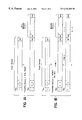
- an extra number of “wildcard” error correcting packets are encoded and transmitted with the original packets to provide a predetermined level of protection against packet loss. For example, if a file contains 180 original packets, an extra 20 wildcard packets may be encoded and transmitted with those 180 original packets, as shown in FIG. 1A, to provide against a loss of 20 original packets (approximately an 11% loss). For the reasons described in that patent application, the addressed subscriber computers can successfully reconstruct the large digital object from the received packets so long as any 180 packets, of the 200 packets transmitted, are successfully received.
- a large file may be broken into smaller “chunks” or “shares”, each of which generally contains the same number of packets, to allow the large file to be transmitted and received by the system.
- Each share is individually encoded, transmitted, received and reconstructed (decoded).
- the file is made whole from the individual reconstructed shares.
- the packets of the shares may also be interleaved to provide additional protection against noise. For example, a data file of 360 original packets and 40 wildcard packets may be divided into two shares of 200 interleaved packets each, as shown in FIG. 1 B.
- the files become larger, the number of shares will increase.
- Those techniques assumes that the underlying packet-level error detection processing does not make any errors, i.e., that when a packet is marked as “good”, it is truly error-free. However, this is not always the case. Occasionally, a packet is marked as “good” when it actually has one or more bit or symbol errors. This may occur if the error detection scheme of the underlying subscriber computer is not robust. For example, the subscriber computer may use a simple checksum error detection scheme to determine whether or not the packet is good. If the checksum fails, then the packet is marked as “bad”. But even if the checksum passes and the packet is marked “good”, there is a certain non-trivial probability that the packet is actually bad.
- the subscriber computer may use an additional level of packet error detection, such as a length check on a word in a header, to reduce the number of these erroneously-marked packets.
- an additional level of packet error detection such as a length check on a word in a header
- a method that verifies whether the original packets have been correctly reconstructed, and if not, locates an erroneously marked packet so that it may be removed from the reconstruction process. The reconstruction, verification and location process may then be repeated, if there are enough remaining packets, until the reconstructed original packets are deemed correct.
- the method of the present invention detects and locates erroneous packets independently of the packet-level error detection processing of the subscriber computer, successful packet reconstruction is not hampered by the inability of the subscriber computer to detect erroneous packets reliably.
- FIG. 1A depicts an example of a file of packets including original packets and wildcard packets
- FIG. 1B depicts an example of a file with shares of interleaved packets
- FIG. 2 is a flowchart of a validation method in accordance with an embodiment of the present invention.
- FIG. 3 is a flowchart of a location method in accordance with another embodiment of the present invention.
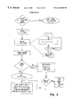
- FIG. 4 depicts a system in which the methods of the embodiments of the present invention may be used.
- a general forward error-correcting (FEC) coding technique (1) encodes a data file of K original packets, yielding N encoded packets to be transmitted, which includes both the information of the original packets and that required for error correction at the receiver (see FIGS. 3A and 4, and corresponding text, of U.S. patent application Ser. No. 08/785,443).
- FEC forward error-correcting
- Another, more specific, coding technique (2) is set forth in that patent application, in which the N transmitted packets consist of the K original packets and N-K encoded error correcting “wildcard” packets (see FIG. 5, and corresponding text, of U.S. patent application Ser. No. 08/785,443).
- the verification and location methods described below may be applied to one-way and two-way communication or computer systems, and especially to those systems that transmit a file from one host computer to many subscriber computers.
- Examples of such “one-to-many” communication and computer systems respectively include satellite broadcast systems and the Internet.
- the host computer transmits the encoded file of packets through a transmitter to one or more receivers, which in turn transfer the received packets to the corresponding subscriber computers for decoding and further processing.
- Each subscriber computer may process the received packets using bit or symbol-level EDAC hardware or software to detect and correct, if possible, any errors at the bit or symbol level, although this step is not necessary.
- the subscriber computer at least checks for erroneous packets at a packet level to determine whether or not the packet is “good” or “bad”, the determination of which is based on the specific packet-level error detection technique used. As described above in the Background Section, a checksum or length check technique may be used for this purpose, as well as any other well-known packet level error detection technique.
- the packets are identified as either “good” or “bad”, and any lost packets are identified as well.
- the packets marked “bad” are discarded.
- the K original packets may be reconstructed so long as there are at least K “good” packets received out of the total N packets transmitted. If less than K “good” packets are received, then the file itself is marked as bad and retransmission of the file is required.
- the first step in this method is to check to see if at least K+1 “good” packets have been received (if only K “good” packets have been received, the K original packets may be reconstructed as set forth in U.S. patent application Ser. No. 08/785,443, but no verification may be performed).
- An extra K+1th “good” packet is selected from the K+1 or more received “good” packets (the selection of this is packet arbitrary, and for the purposes of the following equations, the position this transmitted packet will be denoted by “j”).
- the K “good” packets are then used to both reconstruct the K original packets and to compute a K+1th′ packet such that if the K “good” packets are truly good, the computed K+1th′ packet will be identical to the jth transmitted packet.
- the computation is performed as follows (in which boldface type indicates a vector or matrix quantity, and non-boldface type indicates a scalar quantity):
- x is a 1 ⁇ K vector containing the respective ith bytes of the K original packets, wherein “I” is the total number of bytes in a packet of bytes (1, 2, . . . , ith, . . . , I ⁇ 1, I);
- z is a 1 ⁇ K vector containing the respective ith bytes of the K “good” packets used for reconstruction
- a ⁇ 1 is the inverse of K ⁇ K matrix A formed from the K ⁇ N code generator matrix G, as shown in FIGS. 5 and 6A-6D of U.S. patent application Ser. No. 08/785,443 and described in the corresponding text thereof.
- X k+1 is the ith byte of the K+1th′ packet
- C 1 is a K ⁇ 1 vector formed as follows:
- G j is a K ⁇ 1 vector corresponding to the jth column of the code generator matrix G used in the original encoding process, as shown in FIG. 5 of U.S. patent application Ser. No. 08/785,443 and described in the corresponding text thereof.
- the above equations may be combined into one equation to provide the ith bytes of both the original packets and the K+1th′ packet simultaneously, as follows:
- x′ is a 1 ⁇ K+1 vector containing the respective ith bytes of the K original packets and the ith byte of the K+1th′ packet;
- G′ j (I concatenated with [G j ]), I being a K ⁇ K identity matrix, and thus G′ j is a K ⁇ K+1 size matrix.
- An error vector is computed between the bytes of the selected K+1th packet and the computed K+1th′ packet.
- This error vector is simply the exclusive OR (XOR) of the bytes of the selected K+1th packet and the bytes of the computed K+1th′ packet.
- An error vector of “0” indicates that there is no error in the K “good” packets, thus verifying them. Accordingly, the subscriber can be confident that the reconstructed K original packets are truly error-free, because the probability of obtaining a “0” error vector if there is actually an erroneous packet is extremely remote. However, if there is a non-zero byte in the error vector, the verification method has detected the existence of at least one error in the K+1 packets used in the method.
- the packets on the transmitting side may be interleaved into “chunks” or “shares” of packets, as shown in FIGS. 8A-8D of U.S. patent application Ser. No. 08/785,443 and described in the corresponding text thereof.
- each share of interleaved packets itself becomes a “mini”-file, and thus this embodiment is usually used when relatively large files need to be transmitted and received.
- the above verification process is then performed separately on each received share of packets.
- verification is performed on the first share of received “good” packets ( 1 , 3 , 5 , . . .
- the order in which the individual shares are verified is inconsequential.
- the equations used for verification are the same as the first embodiment, except the number of packets are for each share, rather than for each file. In particular, at least K+1 “good” packets must be received to verify that share.
- a method is provided to locate or “pinpoint” a bad packet, erroneously marked as “good”. This may be done following the verification methods described in the first or second embodiments, that is, for either a non-interleaved file of packets or each interleaved share of packets.
- the verification process can detect the presence of errors in the K+1 packets used therein.
- the verification method has detected the existence of at least one error in the K+1 packets used in the verification processing.
- the first non-zero byte of the error vector will be denoted as “DiffA”.
- the location method shown in FIG. 3 may thus be performed when a non-zero error vector is obtained in the verification process, but only if a K+2th “good” packet is available.
- the first step of this pinpointing method checks to determine that at least K+2 “good” packets have been received. If not, the entire file or share is marked “bad” since pinpointing is not possible. However, if at least K+2 “good” packets have been received, a K+2th packet is selected (but not one of the K+1 packets used in the preceding verification process). For the following equations, this packet will be arbitrarily assumed to be at the mth transmitting position. Using the following equations, a K+2th′ packet, which should be identical to the mth transmitted packet, is computed:
- X k+2 is the ith byte of the K+2th′ packet
- C 2 is a K ⁇ 1 vector formed as follows:
- G m is a K ⁇ 1 vector corresponding to the mth column of the code generator matrix G used in the original encoding process, as shown in FIG. 5 of U.S. patent application Ser. No. 08/785,443, now U.S. Pat. No. 6,012,159, and described in the corresponding text thereof.
- a second error vector is computed between the bytes of the selected K+2th packet and the computed K+2th′ packet.
- This second error vector is the exclusive OR (XOR) of the bytes of the selected K+2th packet and the bytes of the computed K+2th′ packet.
- a second error vector of “0” indicates that (1) the K received packets used for reconstructing the K original packets are truly good and may be relied upon, and (2) the K+1th packet used for verification was the bad packet that caused the non-zero DiffA. Thus, the K original packets of the file or share are verified as correct.
- the bad packet is in the K “good” packets and may be found.
- “DiffB” is defined to be the non-zero byte in the second error vector that is at the same position as that of DiffA in the first error vector. The bad packet is located using a technique based on the following equations:
- [DiffA DiffB] ( 000 . . . 00 e n 00 . . . 0 )[C 1 C 2 ],
- e n is the byte of that packet at the same position as DiffA and DiffB, and “n” is the location of the erroneous packet in the 1 ⁇ K vector z corresponding to that byte position.
- [DiffA DiffB] is simply a multiple of row “n” of the K ⁇ 2 matrix formed by column vectors C 1 and C 2 .
- the location “n” of the erroneous packet can thus be found by merely searching the K ⁇ 2 matrix [C 1 C 2 ] for a multiple of [Diff A DiffB], and determining at which row of that matrix that multiple occurs. That row “n” corresponds to the location “n ” of the erroneous packet. Therefore, assuming that only one packet is erroneous, if such a row can be uniquely found in the matrix, then the location of that one erroneous packet can be pinpointed. However, if more than one row is found that is a multiple of [DiffA DiffB], which is unlikely, the entire file or share is marked bad.
- the single erroneous packet can be marked as “bad” and discarded, and the reconstruction process for the file or share can be re-performed with a new set of K received “good” packets.
- re-verification and re-location may be performed, until the file or share has been reconstructed and verified as truly good.
- the location process may be repeated with an extra received “good” packet, i.e., a K+3th packet, if available. If the location of the erroneous packet cannot be found using this extra 3rd packet, the location process may be repeated again and again, if possible, until the erroneous packet is located. At any time, if there are no extra packets to perform the location process, then the file or share is marked “bad”, requiring the retransmission thereof. Of course, if so desired, the number of location attempts may be limited, for example, to just a first attempt using K+2 packets.
- FIG. 4 A block diagram of one possible communication system that implements the above methods is shown in FIG. 4 .
- This is a one-way satellite broadcast system, and includes a host computer 11 , usually a PC.
- the host computer 11 includes or is extended with a transmission communication device 13 for the transfer of data outside the computer.
- the communication device can take the form of a serial card or a computer chip.
- the communication device 13 is connected by a cable to a satellite transmitter device 12 .
- the satellite transmitter device 12 through an attached uplink antenna 14 , broadcasts the encoded data packets to one or more subscriber computers 20 via satellite 16 .
- the encoded packets are received by a downlink antenna 17 (usually submeter in diameter) attached to a satellite receiver device 18 , which in turn is connected to subscriber computer 20 , usually a PC.
- the subscriber computer 20 includes or is extended with a reception communication device 15 to transfer the received packets into the subscriber computer.
- the verification and location methods of the first through third embodiments may be implemented (1) by computer software, (2) by dedicated hardware, or (3) by combinations of software, hardware and firmware of the subscriber computer.
- the computer software may run on a Windows® 95 or Windows® NT® operating system.
- the software preferably runs on a Pentium® 133 MHz PC or better with at least 16 Mbyte RAM and a 1 Gbyte hard drive for storage of the large digital objects.
- the host computer may be set up with a relational database, a graphical user interface, and list/addressing software and transmission communication software to communicate with the transmission communication device. Data files are transmitted and received using a packet-based broadcast protocol at speeds of over 8.44 Mbps in a dedicated computer.
- the subscriber computer may be set up with a local database, a graphical user interface and receive communication software to communicate with the receiver communication device.
- the packets may be encoded using a computer separate from the host computer.
- the host computer is responsible for transmitting the encoded packets.
- separate computers may be used to receive the transmitted packets and to reconstruct and verify the files (and, if necessary, to locate any erroneous packets thereof).
- Any type of digital file may be transmitted and received.
- These files may include, but are not limited to, video files (MPEG, M-JPEG), electronic documents (PDF), color images (TIF), press clippings, interactive training (CD-I, CD-ROM), news feeds, music and audio (WAV), compound documents, and other multimedia files.
Abstract
Description
| x′ | = | x concatenated with xk+1 | ||
| = | zA−1 concatenated with zC1 | |||
| = | zA−1G′j, where | |||
Claims (10)
Priority Applications (2)
| Application Number | Priority Date | Filing Date | Title |
|---|---|---|---|
| US09/314,120 US6336200B1 (en) | 1998-05-22 | 1999-05-19 | Method for validating communicated packets of data and for locating erroneous packets |
| US10/029,670 US6606723B2 (en) | 1998-05-22 | 2001-12-31 | System, computer-readable medium, and method for validating communicated packets of data and for locating erroneous packets |
Applications Claiming Priority (2)
| Application Number | Priority Date | Filing Date | Title |
|---|---|---|---|
| US8660498P | 1998-05-22 | 1998-05-22 | |
| US09/314,120 US6336200B1 (en) | 1998-05-22 | 1999-05-19 | Method for validating communicated packets of data and for locating erroneous packets |
Related Child Applications (1)
| Application Number | Title | Priority Date | Filing Date |
|---|---|---|---|
| US10/029,670 Division US6606723B2 (en) | 1998-05-22 | 2001-12-31 | System, computer-readable medium, and method for validating communicated packets of data and for locating erroneous packets |
Publications (1)
| Publication Number | Publication Date |
|---|---|
| US6336200B1 true US6336200B1 (en) | 2002-01-01 |
Family
ID=26774936
Family Applications (2)
| Application Number | Title | Priority Date | Filing Date |
|---|---|---|---|
| US09/314,120 Expired - Lifetime US6336200B1 (en) | 1998-05-22 | 1999-05-19 | Method for validating communicated packets of data and for locating erroneous packets |
| US10/029,670 Expired - Lifetime US6606723B2 (en) | 1998-05-22 | 2001-12-31 | System, computer-readable medium, and method for validating communicated packets of data and for locating erroneous packets |
Family Applications After (1)
| Application Number | Title | Priority Date | Filing Date |
|---|---|---|---|
| US10/029,670 Expired - Lifetime US6606723B2 (en) | 1998-05-22 | 2001-12-31 | System, computer-readable medium, and method for validating communicated packets of data and for locating erroneous packets |
Country Status (1)
| Country | Link |
|---|---|
| US (2) | US6336200B1 (en) |
Cited By (35)
| Publication number | Priority date | Publication date | Assignee | Title |
|---|---|---|---|---|
| US6606723B2 (en) * | 1998-05-22 | 2003-08-12 | Kencast, Inc. | System, computer-readable medium, and method for validating communicated packets of data and for locating erroneous packets |
| US6609223B1 (en) * | 1999-04-06 | 2003-08-19 | Kencast, Inc. | Method for packet-level fec encoding, in which on a source packet-by-source packet basis, the error correction contributions of a source packet to a plurality of wildcard packets are computed, and the source packet is transmitted thereafter |
| US6674805B1 (en) | 2000-05-02 | 2004-01-06 | Ati Technologies, Inc. | System for controlling a clock signal for synchronizing a counter to a received value and method thereof |
| US6724737B1 (en) * | 1999-06-17 | 2004-04-20 | Lockheed Martin Global Telecommunications, Inc | System for controlling communications between a terminal and satellite and method therefore |
| US6763390B1 (en) | 2000-01-24 | 2004-07-13 | Ati Technologies, Inc. | Method and system for receiving and framing packetized data |
| US6763492B1 (en) * | 2000-09-26 | 2004-07-13 | Qualcomm Incorporated | Method and apparatus for encoding of linear block codes |
| US6778533B1 (en) | 2000-01-24 | 2004-08-17 | Ati Technologies, Inc. | Method and system for accessing packetized elementary stream data |
| US6785336B1 (en) | 2000-01-24 | 2004-08-31 | Ati Technologies, Inc. | Method and system for retrieving adaptation field data associated with a transport packet |
| US6804266B1 (en) | 2000-01-24 | 2004-10-12 | Ati Technologies, Inc. | Method and apparatus for handling private data from transport stream packets |
| US20050060420A1 (en) * | 2003-09-11 | 2005-03-17 | Kovacevic Branko D. | System for decoding multimedia data and method thereof |
| US6885680B1 (en) | 2000-01-24 | 2005-04-26 | Ati International Srl | Method for synchronizing to a data stream |
| US6988238B1 (en) * | 2000-01-24 | 2006-01-17 | Ati Technologies, Inc. | Method and system for handling errors and a system for receiving packet stream data |
| US20060029101A1 (en) * | 2004-08-06 | 2006-02-09 | Williams Matthew R | System and method for higher throughput through a transportation network |
| US6999424B1 (en) | 2000-01-24 | 2006-02-14 | Ati Technologies, Inc. | Method for displaying data |
| US20060064626A1 (en) * | 2004-09-22 | 2006-03-23 | Kencast, Inc. | System, method and apparatus for FEC encoding and decoding |
| US20070033496A1 (en) * | 2005-07-14 | 2007-02-08 | Hitachi, Ltd. | System and method for adjusting BER/PER to increase network stream-based transmission rates |
| US20080098284A1 (en) * | 2006-10-18 | 2008-04-24 | Kencast, Inc. | Systems, methods, apparatus, and computer program products for providing forward error correction with low latency |
| US7366961B1 (en) | 2000-01-24 | 2008-04-29 | Ati Technologies, Inc. | Method and system for handling errors |
| US20080178360A1 (en) * | 2007-01-31 | 2008-07-31 | Nike, Inc. | Leg guard |
| US20080244001A1 (en) * | 2007-03-27 | 2008-10-02 | Kencast, Inc. | Systems, methods, apparatus and computer program products for providing packet-level fec with higher throughput using user datagram protocol (udp) |
| US20080304483A1 (en) * | 2004-08-06 | 2008-12-11 | Ipeak Networks Incorporated | System and method for achieving accelerated throughput |
| US20090210773A1 (en) * | 2008-02-08 | 2009-08-20 | Kencast, Inc. | Systems, methods, apparatus and computer program products for highly reliable file delivery using compound and braided fec encoding and decoding |
| US7739580B1 (en) | 2005-02-17 | 2010-06-15 | Kencast, Inc. | System, method and apparatus for reducing blockage losses on information distribution networks |
| US20100220728A1 (en) * | 2004-08-06 | 2010-09-02 | Ipeak Networks Incorporated | System and method for achieving accelerated throughput |
| US20110141961A1 (en) * | 2009-12-15 | 2011-06-16 | Hong Kong Applied Science And Technology Research Institute Co., Ltd. | Method of error correction for a multicast message |
| US8223643B1 (en) | 2005-09-06 | 2012-07-17 | Kencast, Inc. | Method for packet-level FEC encoding a stream of source packets using shifted interleaving |
| US8260109B2 (en) | 2000-11-06 | 2012-09-04 | Ati Technologies Ulc | System for digital time shifting and method thereof |
| US8284845B1 (en) | 2000-01-24 | 2012-10-09 | Ati Technologies Ulc | Method and system for handling data |
| US8437370B2 (en) | 2011-02-04 | 2013-05-07 | LiveQoS Inc. | Methods for achieving target loss ratio |
| US8717900B2 (en) | 2011-02-07 | 2014-05-06 | LivQoS Inc. | Mechanisms to improve the transmission control protocol performance in wireless networks |
| US20150074484A1 (en) * | 2013-09-11 | 2015-03-12 | Panasonic Corporation | Communication control apparatus, communication control method, and computer-readable non-transitory recording medium |
| US9189307B2 (en) | 2004-08-06 | 2015-11-17 | LiveQoS Inc. | Method of improving the performance of an access network for coupling user devices to an application server |
| US9590913B2 (en) | 2011-02-07 | 2017-03-07 | LiveQoS Inc. | System and method for reducing bandwidth usage of a network |
| US9647952B2 (en) | 2004-08-06 | 2017-05-09 | LiveQoS Inc. | Network quality as a service |
| US10951743B2 (en) | 2011-02-04 | 2021-03-16 | Adaptiv Networks Inc. | Methods for achieving target loss ratio |
Citations (4)
| Publication number | Priority date | Publication date | Assignee | Title |
|---|---|---|---|---|
| US4907277A (en) * | 1983-10-28 | 1990-03-06 | International Business Machines Corp. | Method of reconstructing lost data in a digital voice transmission system and transmission system using said method |
| US5600663A (en) * | 1994-11-16 | 1997-02-04 | Lucent Technologies Inc. | Adaptive forward error correction system |
| US6012159A (en) * | 1996-01-17 | 2000-01-04 | Kencast, Inc. | Method and system for error-free data transfer |
| US6052819A (en) * | 1997-01-17 | 2000-04-18 | Scientific-Atlanta, Inc. | System and method for detecting correcting and discarding corrupted data packets in a cable data delivery system |
Family Cites Families (1)
| Publication number | Priority date | Publication date | Assignee | Title |
|---|---|---|---|---|
| US6336200B1 (en) * | 1998-05-22 | 2002-01-01 | Kencast, Inc. | Method for validating communicated packets of data and for locating erroneous packets |
-
1999
- 1999-05-19 US US09/314,120 patent/US6336200B1/en not_active Expired - Lifetime
-
2001
- 2001-12-31 US US10/029,670 patent/US6606723B2/en not_active Expired - Lifetime
Patent Citations (4)
| Publication number | Priority date | Publication date | Assignee | Title |
|---|---|---|---|---|
| US4907277A (en) * | 1983-10-28 | 1990-03-06 | International Business Machines Corp. | Method of reconstructing lost data in a digital voice transmission system and transmission system using said method |
| US5600663A (en) * | 1994-11-16 | 1997-02-04 | Lucent Technologies Inc. | Adaptive forward error correction system |
| US6012159A (en) * | 1996-01-17 | 2000-01-04 | Kencast, Inc. | Method and system for error-free data transfer |
| US6052819A (en) * | 1997-01-17 | 2000-04-18 | Scientific-Atlanta, Inc. | System and method for detecting correcting and discarding corrupted data packets in a cable data delivery system |
Cited By (67)
| Publication number | Priority date | Publication date | Assignee | Title |
|---|---|---|---|---|
| US6606723B2 (en) * | 1998-05-22 | 2003-08-12 | Kencast, Inc. | System, computer-readable medium, and method for validating communicated packets of data and for locating erroneous packets |
| US6609223B1 (en) * | 1999-04-06 | 2003-08-19 | Kencast, Inc. | Method for packet-level fec encoding, in which on a source packet-by-source packet basis, the error correction contributions of a source packet to a plurality of wildcard packets are computed, and the source packet is transmitted thereafter |
| US6724737B1 (en) * | 1999-06-17 | 2004-04-20 | Lockheed Martin Global Telecommunications, Inc | System for controlling communications between a terminal and satellite and method therefore |
| US6804266B1 (en) | 2000-01-24 | 2004-10-12 | Ati Technologies, Inc. | Method and apparatus for handling private data from transport stream packets |
| US8284845B1 (en) | 2000-01-24 | 2012-10-09 | Ati Technologies Ulc | Method and system for handling data |
| US7366961B1 (en) | 2000-01-24 | 2008-04-29 | Ati Technologies, Inc. | Method and system for handling errors |
| US6778533B1 (en) | 2000-01-24 | 2004-08-17 | Ati Technologies, Inc. | Method and system for accessing packetized elementary stream data |
| US6785336B1 (en) | 2000-01-24 | 2004-08-31 | Ati Technologies, Inc. | Method and system for retrieving adaptation field data associated with a transport packet |
| US7376692B2 (en) | 2000-01-24 | 2008-05-20 | Ati Technologies, Inc. | Method and system for receiving and framing packetized data |
| US20050021813A1 (en) * | 2000-01-24 | 2005-01-27 | Ati Technologies, Inc. | Method and system for receiving and framing packetized data |
| US6999424B1 (en) | 2000-01-24 | 2006-02-14 | Ati Technologies, Inc. | Method for displaying data |
| US6885680B1 (en) | 2000-01-24 | 2005-04-26 | Ati International Srl | Method for synchronizing to a data stream |
| US6988238B1 (en) * | 2000-01-24 | 2006-01-17 | Ati Technologies, Inc. | Method and system for handling errors and a system for receiving packet stream data |
| US6763390B1 (en) | 2000-01-24 | 2004-07-13 | Ati Technologies, Inc. | Method and system for receiving and framing packetized data |
| US6674805B1 (en) | 2000-05-02 | 2004-01-06 | Ati Technologies, Inc. | System for controlling a clock signal for synchronizing a counter to a received value and method thereof |
| US6763492B1 (en) * | 2000-09-26 | 2004-07-13 | Qualcomm Incorporated | Method and apparatus for encoding of linear block codes |
| US8260109B2 (en) | 2000-11-06 | 2012-09-04 | Ati Technologies Ulc | System for digital time shifting and method thereof |
| USRE47054E1 (en) | 2000-11-06 | 2018-09-18 | Ati Technologies Ulc | System for digital time shifting and method thereof |
| US20050060420A1 (en) * | 2003-09-11 | 2005-03-17 | Kovacevic Branko D. | System for decoding multimedia data and method thereof |
| US20080304483A1 (en) * | 2004-08-06 | 2008-12-11 | Ipeak Networks Incorporated | System and method for achieving accelerated throughput |
| US8009696B2 (en) | 2004-08-06 | 2011-08-30 | Ipeak Networks Incorporated | System and method for achieving accelerated throughput |
| US11445052B2 (en) | 2004-08-06 | 2022-09-13 | Adaptiv Networks Inc. | System and method for achieving accelerated throughput |
| US8548003B2 (en) | 2004-08-06 | 2013-10-01 | LiveQoS Inc. | System and method for achieving accelerated throughput |
| US20060029101A1 (en) * | 2004-08-06 | 2006-02-09 | Williams Matthew R | System and method for higher throughput through a transportation network |
| US10574742B2 (en) | 2004-08-06 | 2020-02-25 | LiveQoS Inc. | Network quality as a service |
| US9893836B2 (en) | 2004-08-06 | 2018-02-13 | LiveQoS Inc. | System and method for achieving accelerated throughput |
| US20110206043A1 (en) * | 2004-08-06 | 2011-08-25 | Ipeak Networks Incorporated | System and method for achieving accelerated throughput |
| US7742501B2 (en) | 2004-08-06 | 2010-06-22 | Ipeak Networks Incorporated | System and method for higher throughput through a transportation network |
| US7953114B2 (en) | 2004-08-06 | 2011-05-31 | Ipeak Networks Incorporated | System and method for achieving accelerated throughput |
| US20100220728A1 (en) * | 2004-08-06 | 2010-09-02 | Ipeak Networks Incorporated | System and method for achieving accelerated throughput |
| US20100272122A1 (en) * | 2004-08-06 | 2010-10-28 | Ipeak Networks Incorporated | System and method for achieving accelerated throughput |
| US9647952B2 (en) | 2004-08-06 | 2017-05-09 | LiveQoS Inc. | Network quality as a service |
| US9379913B2 (en) | 2004-08-06 | 2016-06-28 | LiveQoS Inc. | System and method for achieving accelerated throughput |
| US20110103388A1 (en) * | 2004-08-06 | 2011-05-05 | Ipeak Networks Incorporated | System and method for achieving accelerated throughput |
| US9189307B2 (en) | 2004-08-06 | 2015-11-17 | LiveQoS Inc. | Method of improving the performance of an access network for coupling user devices to an application server |
| US20090177948A1 (en) * | 2004-09-22 | 2009-07-09 | Kencast, Inc. | System, Method and Apparatus for FEC Encoding and Decoding |
| US8245096B2 (en) | 2004-09-22 | 2012-08-14 | Kencast, Inc. | System, method and apparatus for FEC encoding and decoding |
| US20060064626A1 (en) * | 2004-09-22 | 2006-03-23 | Kencast, Inc. | System, method and apparatus for FEC encoding and decoding |
| US7533324B2 (en) | 2004-09-22 | 2009-05-12 | Kencast, Inc. | System, method and apparatus for FEC encoding and decoding |
| US20100218074A1 (en) * | 2005-02-17 | 2010-08-26 | Kencast, Inc. | System, Method and Apparatus for Reducing Blockage Losses on Information Distribution Networks |
| US7739580B1 (en) | 2005-02-17 | 2010-06-15 | Kencast, Inc. | System, method and apparatus for reducing blockage losses on information distribution networks |
| US8402350B2 (en) | 2005-02-17 | 2013-03-19 | Kencast, Inc. | System, method and apparatus for reducing blockage losses on information distribution networks |
| US20070033496A1 (en) * | 2005-07-14 | 2007-02-08 | Hitachi, Ltd. | System and method for adjusting BER/PER to increase network stream-based transmission rates |
| US8223643B1 (en) | 2005-09-06 | 2012-07-17 | Kencast, Inc. | Method for packet-level FEC encoding a stream of source packets using shifted interleaving |
| US8707139B2 (en) | 2006-10-18 | 2014-04-22 | Kencast, Inc. | Systems, methods, apparatus, and computer program products for providing forward error correction with low latency |
| US20080098284A1 (en) * | 2006-10-18 | 2008-04-24 | Kencast, Inc. | Systems, methods, apparatus, and computer program products for providing forward error correction with low latency |
| US10164736B2 (en) | 2006-10-18 | 2018-12-25 | Kencast, Inc. | Systems, methods, apparatus, and computer program products for providing forward error correction with low latency |
| US9397783B2 (en) | 2006-10-18 | 2016-07-19 | Kencast, Inc. | Systems, methods, apparatus, and computer program products for providing forward error correction with low latency |
| US20080178360A1 (en) * | 2007-01-31 | 2008-07-31 | Nike, Inc. | Leg guard |
| US7832017B2 (en) | 2007-01-31 | 2010-11-16 | Nike, Inc. | Leg guard |
| US20110016597A1 (en) * | 2007-01-31 | 2011-01-27 | Nike, Inc. | Leg Guard |
| US7949778B2 (en) | 2007-03-27 | 2011-05-24 | Kencast, Inc. | Systems, methods, apparatus and computer program products for providing packet-level FEC with higher throughput using user datagram protocol (UDP) |
| US20080244001A1 (en) * | 2007-03-27 | 2008-10-02 | Kencast, Inc. | Systems, methods, apparatus and computer program products for providing packet-level fec with higher throughput using user datagram protocol (udp) |
| US8726136B2 (en) | 2008-02-08 | 2014-05-13 | Kencast, Inc. | Systems, methods, apparatus and computer program products for highly reliable file delivery using compound and braided FEC encoding and decoding |
| US8418034B2 (en) | 2008-02-08 | 2013-04-09 | Kencast, Inc. | Systems, methods, apparatus and computer program products for highly reliable file delivery using compound and braided FEC encoding and decoding |
| US9071274B2 (en) | 2008-02-08 | 2015-06-30 | Kencast, Inc. | Systems, methods, apparatus and computer program products for highly reliable file delivery using compound and braided FEC encoding and decoding |
| US20090210773A1 (en) * | 2008-02-08 | 2009-08-20 | Kencast, Inc. | Systems, methods, apparatus and computer program products for highly reliable file delivery using compound and braided fec encoding and decoding |
| US20110141961A1 (en) * | 2009-12-15 | 2011-06-16 | Hong Kong Applied Science And Technology Research Institute Co., Ltd. | Method of error correction for a multicast message |
| US8397120B2 (en) * | 2009-12-15 | 2013-03-12 | Hong Kong Applied Science And Technology Research Institute Co. Ltd. | Method of error correction for a multicast message |
| US10951743B2 (en) | 2011-02-04 | 2021-03-16 | Adaptiv Networks Inc. | Methods for achieving target loss ratio |
| US8437370B2 (en) | 2011-02-04 | 2013-05-07 | LiveQoS Inc. | Methods for achieving target loss ratio |
| US9647945B2 (en) | 2011-02-07 | 2017-05-09 | LiveQoS Inc. | Mechanisms to improve the transmission control protocol performance in wireless networks |
| US9590913B2 (en) | 2011-02-07 | 2017-03-07 | LiveQoS Inc. | System and method for reducing bandwidth usage of a network |
| US10057178B2 (en) | 2011-02-07 | 2018-08-21 | LiveQoS Inc. | System and method for reducing bandwidth usage of a network |
| US8717900B2 (en) | 2011-02-07 | 2014-05-06 | LivQoS Inc. | Mechanisms to improve the transmission control protocol performance in wireless networks |
| US20150074484A1 (en) * | 2013-09-11 | 2015-03-12 | Panasonic Corporation | Communication control apparatus, communication control method, and computer-readable non-transitory recording medium |
| US9306824B2 (en) * | 2013-09-11 | 2016-04-05 | Panasonic Intellectual Property Management Co., Ltd. | Communication control apparatus, communication control method, and computer-readable non-transitory recording medium |
Also Published As
| Publication number | Publication date |
|---|---|
| US6606723B2 (en) | 2003-08-12 |
| US20020078414A1 (en) | 2002-06-20 |
Similar Documents
| Publication | Publication Date | Title |
|---|---|---|
| US6336200B1 (en) | Method for validating communicated packets of data and for locating erroneous packets | |
| US6012159A (en) | Method and system for error-free data transfer | |
| US5968197A (en) | Method and apparatus for data recovery | |
| US6421803B1 (en) | System and method for implementing hybrid automatic repeat request using parity check combining | |
| US20040117722A1 (en) | Performance of communication systems using forward error correction | |
| US5870406A (en) | Automatic repeat request(ARQ) data communications method and apparatus | |
| US5517508A (en) | Method and apparatus for detection and error correction of packetized digital data | |
| EP1528742B1 (en) | Method and apparatus for providing signal acquisition and frame synchronization in a hierarchical modulation scheme | |
| KR100608042B1 (en) | Encoding method for radio transceiving of multimedia data and device thereof | |
| US20020049939A1 (en) | Method and system for reliable broadcasting of data files and streams | |
| EP1391042B1 (en) | Hierarchical block coding for a packet-based communications system | |
| JPH1188463A (en) | Transmitting method for data block | |
| US20070165673A1 (en) | Method for reconstructing lost packets using a binary parity check | |
| EP1423954A1 (en) | Encoding and decoding ultra-wideband information | |
| US7716559B2 (en) | Method for lost packet reconstruction and device for carrying out said method | |
| US7215683B2 (en) | Method and apparatus for protecting against packet losses in packet-oriented data transmission | |
| US7023899B2 (en) | Method for reliable signaling information transmission in a wireless communication system | |
| CA2364072C (en) | Interconnect system with error correction | |
| US20070127458A1 (en) | Data communication method for detecting slipped bit errors in received data packets | |
| US20040181740A1 (en) | Communicating method, transmitting apparatus, receiving apparatus, and communicating system including them | |
| US6781987B1 (en) | Method for packet transmission with error detection codes | |
| EP1075744B1 (en) | Data transmission system with automatic repeat request | |
| JP2775710B2 (en) | Spread spectrum communication equipment | |
| US20040261007A1 (en) | Multidimensional turbo product code decoding of encoded data transmitted over diversity channel | |
| Gold et al. | Error correction strategies for data broadcasting |
Legal Events
| Date | Code | Title | Description |
|---|---|---|---|
| AS | Assignment |
Owner name: KENCAST, INC., CONNECTICUT Free format text: ASSIGNMENT OF ASSIGNORS INTEREST;ASSIGNOR:WOLFGANG, H. LEWIS;REEL/FRAME:009973/0820 Effective date: 19990517 |
|
| STCF | Information on status: patent grant |
Free format text: PATENTED CASE |
|
| CC | Certificate of correction | ||
| FPAY | Fee payment |
Year of fee payment: 4 |
|
| REMI | Maintenance fee reminder mailed | ||
| FPAY | Fee payment |
Year of fee payment: 8 |
|
| SULP | Surcharge for late payment |
Year of fee payment: 7 |
|
| REMI | Maintenance fee reminder mailed | ||
| FPAY | Fee payment |
Year of fee payment: 12 |
|
| SULP | Surcharge for late payment |
Year of fee payment: 11 |
|
| AS | Assignment |
Owner name: ENHANCED CAPITAL CONNECTICUT FUND V, LLC, CONNECTI Free format text: PATENT SECURITY AGREEMENT;ASSIGNOR:KENCAST, INC.;REEL/FRAME:038439/0381 Effective date: 20160415 |
|
| AS | Assignment |
Owner name: KENCAST, INC., CONNECTICUT Free format text: RELEASE BY SECURED PARTY;ASSIGNOR:EDGEMONT CAPITAL LLC;REEL/FRAME:046610/0551 Effective date: 20180712 |
|
| AS | Assignment |
Owner name: KENCAST, INC., CONNECTICUT Free format text: ASSIGNMENT OF ASSIGNORS INTEREST;ASSIGNOR:WOLFGANG, H. LEWIS;REEL/FRAME:051269/0266 Effective date: 20191113 |