US6343071B1 - Wireless desktop area network system - Google Patents
Wireless desktop area network system Download PDFInfo
- Publication number
- US6343071B1 US6343071B1 US08/875,697 US87569797A US6343071B1 US 6343071 B1 US6343071 B1 US 6343071B1 US 87569797 A US87569797 A US 87569797A US 6343071 B1 US6343071 B1 US 6343071B1
- Authority
- US
- United States
- Prior art keywords
- node
- network
- transmitting
- transmission
- receiving
- Prior art date
- Legal status (The legal status is an assumption and is not a legal conclusion. Google has not performed a legal analysis and makes no representation as to the accuracy of the status listed.)
- Expired - Lifetime
Links
Images


Classifications
-
- H—ELECTRICITY
- H04—ELECTRIC COMMUNICATION TECHNIQUE
- H04L—TRANSMISSION OF DIGITAL INFORMATION, e.g. TELEGRAPHIC COMMUNICATION
- H04L1/00—Arrangements for detecting or preventing errors in the information received
- H04L1/12—Arrangements for detecting or preventing errors in the information received by using return channel
- H04L1/16—Arrangements for detecting or preventing errors in the information received by using return channel in which the return channel carries supervisory signals, e.g. repetition request signals
- H04L1/1607—Details of the supervisory signal
-
- H—ELECTRICITY
- H04—ELECTRIC COMMUNICATION TECHNIQUE
- H04L—TRANSMISSION OF DIGITAL INFORMATION, e.g. TELEGRAPHIC COMMUNICATION
- H04L1/00—Arrangements for detecting or preventing errors in the information received
- H04L2001/0092—Error control systems characterised by the topology of the transmission link
- H04L2001/0094—Bus
-
- H—ELECTRICITY
- H04—ELECTRIC COMMUNICATION TECHNIQUE
- H04W—WIRELESS COMMUNICATION NETWORKS
- H04W74/00—Wireless channel access, e.g. scheduled or random access
- H04W74/08—Non-scheduled or contention based access, e.g. random access, ALOHA, CSMA [Carrier Sense Multiple Access]
- H04W74/0808—Non-scheduled or contention based access, e.g. random access, ALOHA, CSMA [Carrier Sense Multiple Access] using carrier sensing, e.g. as in CSMA
- H04W74/0816—Non-scheduled or contention based access, e.g. random access, ALOHA, CSMA [Carrier Sense Multiple Access] using carrier sensing, e.g. as in CSMA carrier sensing with collision avoidance
-
- H—ELECTRICITY
- H04—ELECTRIC COMMUNICATION TECHNIQUE
- H04W—WIRELESS COMMUNICATION NETWORKS
- H04W74/00—Wireless channel access, e.g. scheduled or random access
- H04W74/08—Non-scheduled or contention based access, e.g. random access, ALOHA, CSMA [Carrier Sense Multiple Access]
- H04W74/0808—Non-scheduled or contention based access, e.g. random access, ALOHA, CSMA [Carrier Sense Multiple Access] using carrier sensing, e.g. as in CSMA
- H04W74/0825—Non-scheduled or contention based access, e.g. random access, ALOHA, CSMA [Carrier Sense Multiple Access] using carrier sensing, e.g. as in CSMA carrier sensing with collision detection
-
- H—ELECTRICITY
- H04—ELECTRIC COMMUNICATION TECHNIQUE
- H04W—WIRELESS COMMUNICATION NETWORKS
- H04W84/00—Network topologies
- H04W84/02—Hierarchically pre-organised networks, e.g. paging networks, cellular networks, WLAN [Wireless Local Area Network] or WLL [Wireless Local Loop]
- H04W84/10—Small scale networks; Flat hierarchical networks
-
- H—ELECTRICITY
- H04—ELECTRIC COMMUNICATION TECHNIQUE
- H04W—WIRELESS COMMUNICATION NETWORKS
- H04W92/00—Interfaces specially adapted for wireless communication networks
- H04W92/16—Interfaces between hierarchically similar devices
- H04W92/18—Interfaces between hierarchically similar devices between terminal devices
Definitions
- the invention relates to a wireless communication network system for exchanging data packets between computers, and between computers and peripheral equipments such as printers, digitizing tablets, keyboards, and pointing devices or mice, within a small local area such as an office or closely arranged group of offices.
- Wireless communication networks may vary from one using a point-to-point type system where one node speaks only to one other node as in a peer-to-peer or host-to-host system, or a point and shoot type system that operates much like a television remote control in communicating with other nodes, to a true multinode system continually requiring multiple communication paths.
- U.S. Pat. Nos. 4,232,299; 4,775,928; 4,992,787, 5,075,792; 5,204,768; and 5,307,297 are representative.
- All wireless communication networks can be conveniently classified in accordance with the area they cover.
- a network that covers an area having a cross-distance of miles is generally referred to as a metropolitan area network (MAN) or wide area network (WAN).
- a wireless network that covers cross-distances of the order of hundreds of feet generally is referred to as a local area network (LAN).
- MAN metropolitan area network
- WAN wide area network
- LAN local area network
- Each of the above networks employ complex and costly communication protocols, which in turn require expensive hardware for implementation in accommodating information exchanges between multiple nodes.
- U.S. Pat. Nos. 4,665,519 and 5,241,542 are representative.
- a multiple access method can be described as either circuit switched or packet switched.
- Circuit switched networks are those where a connection must be continuously maintained, as with a telephone.
- a packet switched network allocates capacity to users as a slice of time, but the connection between users only lasts for the duration of the packet. During the transmission of the packet, however, the entire capacity of the channel is available to the transmitting node. This transient connection of a packet switched network is ideal for situations where a relatively large number of nodes need to make infrequent connections to each other to communicate by rapid bursts of information.
- TDMA time division multiple access
- FDMA frequency division multiple access
- CDMA code division multiple access
- CSMA carrier sense multiple access
- the TDMA, FDMA and CDMA control schemes have been successfully used with networks where continuous data streams are issued by a small number of nodes. Where data packets are issued rapidly from a large number of nodes, however, the CSMA control scheme has been favored. In wireless systems where relatively short bursts of data or data packets are transmitted at high speeds, the CSMA control scheme is ideal.
- U.S. Pat. Nos. 4,665,519 and 5,241,542 are representative.
- a Collision Detection system usually is used in which a node compares a signal traveling over a wire with a signal that it is attempting to send. No signal is transmitted by the node as long as the compared signals differ, or until no signals are detected in the transmission channel.
- a network node has both a transmitter and a receiver means, and the receiver means stays energized until such time as a transmission of information is required, the occurrence of activity in a transmission channel can be detected.
- the transmission can be delayed until no activity in the transmission channel is detected.
- a receiver in such an event will likely receive a corrupted packet and not acknowledge a successful transmission.
- Collision Avoidance is used, wherein a transmitter waits or pauses before retransmitting if no acknowledgement is received within a specified time period after a first transmission.
- the transmission wait time is referred to as the backoff period.
- the backoff period is chosen randomly according to a statistical rule.
- CSMA/CA multiple access control The combination of CSMA and Collision Avoidance is referred to as CSMA/CA multiple access control.
- Wireless systems have been made that include CSMA/CA capabilities implemented with a MAN, WAN or LAN protocol. Such complex and expensive systems are not practical for a small area network such as a Desktop Area Network (DAN), where communication is desired with a computer or peripheral device, between computers, or between a computer and a peripheral device located in an office or in adjacent offices.
- DAN Desktop Area Network
- U.S. Pat. No. 4,665,519 may be said to be representative, it is a low performance, narrow band system which requires a complex and costly conversion of an RS-232C serial interface into an HDLC multipoint protocol through use of manually set DIP switches. Further, the patent discloses the use of random backoffs and manually switched frequencies, and thus is not a true CSMA system.
- the invention is a wireless, high performance, broadband Desktop Area Network (DAN) system, which includes CSMA ⁇ CA multiple access control with Collision Avoidance that is implemented by utilizing a serial bus data packet protocol to accommodate wireless communication among multiple nodes. Synchronized data packet exchanges are accommodated with the between computers, between computers and peripheral equipments, and with peripheral equipments including but not limited to keyboards, printers, facsimilie machines, digitizing tablets, and pointers or mice.
- DAN broadband Desktop Area Network
- a timing recovery method is used which is based upon a data packet structure that includes a preamble with an alternating data stream from which timing information may be extracted to synchronize the processing of the data packet.
- CSMA multiple access control is implemented by utilizing a serial bus data packet protocol to accommodate wireless exchanges of data packet information not only between a computer and peripheral equipment, but also between computers (peer to peer).
- interference between nodes in transmitting messages is controlled through use of both a delay method which causes a transmitting node to wait until a communication channel is idle before transmitting data packet information, and a Collision Avoidance method in which all transmitting nodes upon failing to receive an acknowledgement signal from a target receiving node will wait for a period of time (proportional to the transmitting node's network address) before attempting to retransmit the message.
- the CSMA ⁇ CA multiple access control and timing recovery methods are not hardware dependent on the type of interface used to transmit and receive data packets.
- only the controller need by reconfigured for host to host portability of a node subsystem comprising a controller, a transmitter, a receiver and an interface for receiving and sending modulated information data packets.
- both RF and IR transmissions may be accommodated by same data and control protocols.
- network configuration occurs through an automated, interactive process wherein network node addresses for each network node having a wireless network module are stored in host memory for access in selecting those of the network nodes which will form a network configuration in which wireless messages may be exchanged.
- FIG. 1 is a functional block diagram of a network node in accordance with the invention which may alternatively be used in RF or IR modes;
- FIGS. 2A and 2B are alternative functional block diagrams of of Interface 5 of FIG. 1;
- FIG. 3 is a diagram of a preamble structure in a data packet
- FIG. 4 is a diagram of a data packet structure
- FIG. 5A is a detailed functional block diagram of a preferred RF embodiment of the invention.
- FIG. 5B is a detailed functional block diagram of a preferred IR embodiment of the invention.
- FIG. 6A is a logic flow diagram of a receiver media access control (MAC) process of controller 2 of FIG. 1;
- MAC media access control
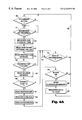
- FIG. 6B is a logic flow diagram of a transmitter MAC process of controller 2 ;
- FIG. 7 is a logic flow diagram of a wireless network configuration process of host 1 .
- a node of a Desktop Area Network is illustrated in which a host system 1 such as a personal computer (PC) or peripheral equipment is in electrical communication with a microcontroller 2 of a wireless network module.
- the microcontroller outputs data received from the host system in accordance with a data packet protocol to line 6 leading to an input of a transmitter 3 , and outputs to the host system 1 demodulated data received on line 7 from the receiver 4 .
- the controller 2 also issues an energize signal on line 9 to the transmitter 3 in response to a transmit request received from the host system 1 , and issues and energize signal on line 8 to the receiver 4 to turn the receiver on when the system is not in a transmit mode.
- the controller 2 in addition issues a control signal on line 10 to place the interface 5 in either a transmit or receive mode.
- Controller 2 , transmitter 3 , receiver 4 and interface 5 comprise a wireless network module which is easily portable from host to host.
- Communication between the controller 2 and the host 1 may occur by way of a variety of port interfaces including but not limited to a parallel port, an RS-232 serial port, a PCMCIA port, and an ACCESS.bus port.
- FIGS. 2A and 2B respectively illustrate an RF antenna 13 which is shared by the receiver 4 and transmitter 3 when the interface 5 is an RF embodiment; and an IR light emitting diode (LED) 14 that is connected to the output of transmitter 3 and an IR sensitive transistor 15 which is connected to the input of receiver 4 when the interface 5 is an IR embodiment.
- LED IR light emitting diode
- the antenna 13 preferably is a whip or loop (OdB) antenna accommodating a received power level of ⁇ 20 dBm at three meters, and during a transmit mode exhibiting a hemispherical or torodial pattern.
- OdB whip or loop
- a data stream from host 1 is received by transmitter 3 from controller 2 as data packets, and is encoded onto a carrier by frequency shift keying with continuous phase modulation.
- the modulated carrier then is sent by transmitter 3 to antenna 13 in interface 5 , where the modulated carrier is broadcast to a receiving target node.
- the receiver of the target node then demodulates the carrier to recover the data packets and read the transmitted message or data.
- FIG. 3 is a graphical illustration of a preamble structure of a data packet that is communicated between computers, between a computer and peripheral equipment, or to a computer or peripheral equipment in a DAN network in accordance with the invention.
- the preamble includes an indeterminate field 16 followed by an alternating data stream of binary ones and zeros 17 , an error correction coding (ECC) field 18 , a run-length limited error (RLE) field 19 , and spare fields 20 and 21 to accommodate optional information.
- ECC error correction coding
- RLE run-length limited error
- FIG. 4 The structure of an entire data packet in accordance with the invention is illustrated in FIG. 4, where a preamble structure 22 is followed by a destination address field 23 , a source address field 24 , a word count field 25 , n data fields 26 - 27 , and a checksum/cyclic redundancy check field 28 to allow data validation by a receiving node.
- the above described data packet structure is in conformance with a wired serial bus protocol referred to as the ACCESS.bus protocol.
- a description of the ACCESS.bus may be purchased from the ACCESS.bus Industry Group as “ACCESS.bus Specifications-Version 2.2”, ACCESS.bus Industry Group, 370 Altair Way, Suite 215, Sunnyvale, Calif. 94086.
- the preferred embodiment described herein uses carrier sense multiple access (CSMA) control to accommodate short bursts of data at high speeds among multiple nodes.
- CSMA carrier sense multiple access
- a delay method is used which causes a transmitter in a network node to pause or wait when activity in the transmission channel is detected.
- a Collision Avoidance (CA) method has been implemented which comes into play when a transmission to a target node is made, but no acknowledgement signal is received from the target node within a specific time period.
- the CA method causes the transmitting node to wait a period of time proportional to the network address of the transmitting node before retransmitting an information signal.
- the combined CSMA and CA functionalities comprise a CSMA/CA access control system.
- FIG. 5A a detailed functional block diagram of an RF preferred embodiment of a DAN network node is illustrated. Communication between the host system 1 and controller 2 occurs over a port interface 30 .
- modulated radio signals are received by the antenna 13 and are carried over bidirectional RF line 32 to RF bandpass filter 33 .
- the output of filter 33 is applied to the input of receiver 4 , where the radio signals are demodulated.
- the receiver may be an integrated circuit sold by Philips Semiconductor Inc. of 811 East Arques Avenue in Sunnyvale, Calif. 94088 as IC circuit Model No. SA626.
- the receiver 4 is a superheterodyne frequency modulation (FM) receiver using a local oscillator frequency of 16.42 megahertz provided by the crystal oscillator 34 .
- Final intermediate frequency filtering is performed by bandpass filter 35 . If a signal is detected by the receiver 4 , the voltage level on the Received Signal Strength Indicator (RSSI) line 36 increases and is compared by comparator 37 to a threshold of the order of ⁇ 40 dBm or 10 dB above noise, whichever is greater. If the threshold is exceeded, the comparator generates a binary detection signal on line 38 . In response to the detection signal, controller 2 executes signal processes which will be further described below.
- RSSI Received Signal Strength Indicator
- the receiver 4 also detects any frequency deviations in the received signal, and issues a voltage with magnitude indicative of the deviation on line 39 .
- the voltage is compared by the comparator 40 with a threshold value equal to approximately one-half of the comparator supply voltage.
- the supply voltage is of the order of 3.3 volts.
- the output of the comparator is a data stream that is applied to an input of controller 2 , where the data stream is converted to a desired data format and sent to the host system 1 by way of the port interface 30 .
- the host system 1 sends data to the controller 2 over the port interface 30 .
- an interrupt is generated in the controller 2 which causes it to execute a series of transmit process steps.
- a signal is applied by the controller 2 to the line 31 to turn the receiver 4 off, and enable the transmitter oscillator 42 which transmits at a center frequency of 27.12 megahertz.
- the signal levels on line 43 cause frequency shifts in the oscillator 42 in a continuous phase transition.
- the output of the oscillator a frequency shifting carrier with continuous phase modulation at a frequency deviation of 100 KHz, is buffered by a common base amplifier 44A, and coupled to the bidirectional RF line 32 for broadcast by antenna 13 .
- FIG. 5B An IR DAN network node is illustrated in block diagram form in FIG. 5B, where like devices have a same reference number as those illustrated in FIG. 5 A.
- modulated IR signals are received by an IR sensitive transistor 15 .
- the base of the transistor 15 is connected to the input of an IR filter 45 .
- the output of filter 45 in turn is connected to the input of an IR receiver 46 .
- the operation and design specifications of the receiver are disclosed in the document entitled, “HPSIR-Wired Serial and Infrared I/O, Architecture External Reference Specification, Version 1.1”, dated Apr. 11, 1991.
- the document is made available by the Hewlett-Packard Optical Communication Division at 350 West Trimble Road, San Jose, Calif. 95131.
- One input of the receiver 46 is connected to line 31 and to an input of pulse shaper 47 .
- the input of pulse shaper 47 is connected to line 43 and the output of the pulse shaper is connected to the input of a common emitter buffer amplifier 44 B.
- the output of the amplifier 44 B in turn is connected to the input of the IR LED diode 14 .
- modulated IR signals received by transistor 15 are applied through IR bandpass filter 45 to IR receiver 46 , where demodulation occurs. If an IR signal is detected by receiver 46 , the voltage level on line 36 increases and is compared to a threshold by comparator 37 as before described.
- the comparator 37 generates a binary detection signal on line 38 if the threshold is exceeded.
- controller 2 executes signal processes which will be further described below.
- the receiver 46 also detects any amplitude deviations in the received signal, and issues a voltage with magnitude indicative of the deviation on line 39 where the voltage is compared by the comparator 40 with the before described threshold value.
- the output of the comparator is a data stream that is applied to an input of controller 2 , where the data stream is converted to a desired data format and sent to the host system 1 by way of the port interface 30 .
- the host system 1 sends data to the controller 2 over the port interface 30 .
- an interrupt is generated in the controller 2 which causes it to execute a series of transmit process steps.
- a signal is applied by the controller 2 to the line 31 to turn the receiver 46 off and enable the p pulse shaper 47 .
- Data to be transmitted is sent by controller 2 along line 43 to the pulse shaper 47 , which converts the data stream to a Hewlett-Packard serial format that is disclosed in the Hewlett-Packard document identified above.
- the output of the pulse shaper is buffered by the amplifier 44 B and applied to the IR LED 14 , which radiates for ⁇ fraction (3/16) ⁇ of a bit time period to indicate a logic 0.
- a logic one is indicated when the LED is turned off for an entire bit time period.
- the transmit and receive functions performed by a DAN network system node are executed in accordance with a media access control (MAC) logic decision process residing in controller 2 , which defines the structure of the data packets and assures the integrity of the information within the packets.
- MAC media access control
- FIG. 6A a logic decision flow diagram of a MAC receive function is illustrated.
- the controller searches for the beginning of a preamble at logic step 51 .
- the initial four bits of the preamble are used to determine the timing of the incoming data fields of the data packet at logic step 52 , and if used, the trailing fields of the preamble are sensed and stored for further processing at logic step 53 .
- the destination address field 23 is read at logic step 54 and compared at logic step 55 with the address of the receiving node. If the address that is read is not the same as the receiving node address, the logic process proceeds to logic step 56 to circulate around an inner loop 57 until the controller senses an end of the transmission. Upon the end of transmission being sensed, the logic decision process proceeds to the outer loop 58 to await a new transmission.
- the logic decision process proceeds from logic step 55 to logic step 59 where the source address 24 of FIG. 4 of the received data packet is read.
- the source address is compared at logic step 60 with an internal list of allowed source addresses. If no coincidence of addresses occurs, the logic decision process transfers to logic step 56 to await the end of the current transmission as before described. If a coincidence occurs, however, the source address is on the internal list of allowed sources and the controller reads the word count in the field 25 of FIG. 4 at logic step 61 to determine the number of data bytes that will be received. The indicated number of data bytes in the data packet then is read at logic step 62 .
- the controller After reading the final data byte, the controller at logic step 63 reads the last word in the data packet, the checksum/CRC field 28 of FIG. 4, and thereafter determines at logic step 64 whether the data packet was received without error. If so, the logic decision process proceeds to logic step 65 to deenergize receiver 4 , and to energize transmitter 3 of FIG. 1 to send an acknowledgement signal by way of the antenna of interface 5 to the source node. The logic decision flow then proceeds to logic step 66 , where the data bytes read from the received data packet are transferred by the controller 2 over port 30 to the host computer 1 of FIG. 1 for further processing. Thereafter, the logic decision flow returns to the outer loop 58 to await the receipt of another transmission.
- checksum/CRC field 28 of FIG. 4 indicates at logic step 64 of FIG. 6A that the data packet was not received error free, the controller does not acknowledge receipt of the data packet. Rather, the logic decision flow proceeds from logic step 64 to the outer loop 58 to await the receipt of another transmission as before described. It is left to the source node to determine whether and when to retransmit a data packet.
- the transmission of a data packet is an interrupt driven event.
- a transmit service process is initialized at logic step 71 .
- the controller thereafter accepts a data packet from the host computer at logic step 72 .
- the data packet then is converted by the controller at logic step 73 to the format previously described and illustrated in FIG. 4 .
- a preamble with timing information is inserted at the beginning of the data packet, and a checkword is appended to the end of the packet to allow the receiving node to verify receipt of an error free data packet.
- the data packet thereupon is ready for wireless transmission by interface 5 of FIG. 1, and the logic decision flow proceeds to logic step 75 to wait until there is no activity in the network before beginning transmission.
- the logic decision flow proceeds to logic step 76 where the controller 2 of FIG. 1 issues the data packet bit stream to the transmitter 3 for transmission by way of the RF antenna in interface 5 .
- the logic decision flow determines at logic step 77 of FIG. 6B whether an acknowledgement from the destination or receiving node has been received. If so, the transmit process is exited at logic step 78 . If not, the logic decision flow awaits the receipt of the acknowledgement by looping through logic step 79 , until either an acknowledgement is received at logic step 77 or timeout occurs at logic step 79 .
- the controller will wait for only a brief period (two seconds or less) before declaring a timeout fault at step 79 . If an acknowledgement is received before timeout, the logic decision flow proceeds from logic step 77 to logic step 78 as before described. If a timeout occurs before an acknowledgement is received, however, the logic decision flow proceeds from logic step 79 to logic step 80 where a timeout error is recognized. The logic decision flow then proceeds to logic step 81 where the number of timeouts that have occurred is compared to a threshold value. If the threshold value has not been exceeded, the logic decision flow waits for a period of time proportional to the numerical network address of the node, and then transfers from logic step 81 to logic step 75 by way of loop 82 to retransmit the data packet as before described.
- the logic decision flow will return to logic step 77 by way of loop 83 . Further, when the number of timeouts that have occurred without receiving an acknowledgement exceeds the previously described threshold value, the logic decision flow will pass through logic step 81 to logic step 84 rather than return by way of loop 82 to the logic step 75 .
- the controller 2 sends the host computer 1 of FIG. 1 a transmission failure flag, and thereafter exits the transmit service process at logic step 85 .
- the MAC logic decision process described above remains the same whether the RF system of FIG. 5A or the IR system of FIG. 5B is used.
- FIG. 7 illustrates a logic decision flow diagram of an interactive network configuration process in host 1 .
- host 1 queries the port interface 30 at logic step 91 to determine whether a wireless network module as illustrated in FIG. 1 is present. If not, host 1 displays a message that indicates no wireless network module is present, and the process is exited at logic step 92 . If, however, a wireless network module is present, the host may request a capabilities string or list of module capabilities at logic step 93 . Upon receipt of the capabilities string, the host 1 displays at logic step 94 a list a valid network nodes in the DAN network.
- the user thereupon selects those nodes which are to be included in the network configuration at logic step 95 , and the host 1 writes a file of node addresses and connections for storage in a host memory at logic step 96 . Thereafter, the file is read by host 1 each time the host is booted, and the information in the file is inserted into the address fields of the data packets to be transmitted. The process then is exited at logic step 97 .
Abstract
Description
Claims (13)
Priority Applications (1)
| Application Number | Priority Date | Filing Date | Title |
|---|---|---|---|
| US08/875,697 US6343071B1 (en) | 1995-01-11 | 1995-01-11 | Wireless desktop area network system |
Applications Claiming Priority (2)
| Application Number | Priority Date | Filing Date | Title |
|---|---|---|---|
| PCT/US1995/000494 WO1996021978A1 (en) | 1995-01-11 | 1995-01-11 | Wireless desktop area network system |
| US08/875,697 US6343071B1 (en) | 1995-01-11 | 1995-01-11 | Wireless desktop area network system |
Publications (1)
| Publication Number | Publication Date |
|---|---|
| US6343071B1 true US6343071B1 (en) | 2002-01-29 |
Family
ID=25366218
Family Applications (1)
| Application Number | Title | Priority Date | Filing Date |
|---|---|---|---|
| US08/875,697 Expired - Lifetime US6343071B1 (en) | 1995-01-11 | 1995-01-11 | Wireless desktop area network system |
Country Status (1)
| Country | Link |
|---|---|
| US (1) | US6343071B1 (en) |
Cited By (24)
| Publication number | Priority date | Publication date | Assignee | Title |
|---|---|---|---|---|
| US20020154653A1 (en) * | 2001-01-02 | 2002-10-24 | Mathilde Benveniste | Random medium access methods with backoff adaptation to traffic |
| US6493351B1 (en) * | 1999-04-21 | 2002-12-10 | Nortel Networks Ltd. | Collision detection on a differential bus |
| US20030012166A1 (en) * | 2001-07-05 | 2003-01-16 | At&T Corp. | Hybrid coordination function (HCF) access through tiered contention and overlapped wireless cell mitigation |
| US6535503B1 (en) * | 1996-10-15 | 2003-03-18 | Nokia Telecommunications | Channel allocation method and radio system using a combination of TDMA and CDMA |
| WO2003041343A2 (en) * | 2001-11-02 | 2003-05-15 | At & T Corp. | Fixed deterministic post-backoff for cyclic prioritized multiple access (cpma) contention-free sessions |
| US20030156553A1 (en) * | 2001-11-02 | 2003-08-21 | At&T Corp. | 'Shield': protecting high priority channel access attempts in overlapped wireless cells |
| US20030174664A1 (en) * | 2001-11-02 | 2003-09-18 | At&T Corp. | Preemptive packet for maintaining contiguity in cyclic prioritized multiple access (CPMA) contention-free sessions |
| US6625163B1 (en) * | 1999-04-21 | 2003-09-23 | Nortel Networks Ltd. | Collision detection on a differential bus |
| US20040047314A1 (en) * | 2002-09-11 | 2004-03-11 | Li Chris Cho-Pin | Adaptive channel access for carrier sense multiple access based systems |
| US20040095911A1 (en) * | 2001-11-02 | 2004-05-20 | At&T Corp. | Fixed deterministic post-backoff for cyclic prioritized multiple access (CPMA) contention-free sessions |
| US6882334B1 (en) * | 1999-12-14 | 2005-04-19 | Gateway, Inc. | Apparatus and method for detection of communication signal loss |
| US20050278756A1 (en) * | 2004-06-12 | 2005-12-15 | Brown Alan E | Information processing apparatus featuring a multi-subsystem wireless bus architecture |
| US20060067308A1 (en) * | 2004-09-24 | 2006-03-30 | Seong-Kwan Cho | Providing subscriber information in voice over IP (VoIP) system |
| US7095754B2 (en) | 2000-11-03 | 2006-08-22 | At&T Corp. | Tiered contention multiple access (TCMA): a method for priority-based shared channel access |
| US20060212911A1 (en) * | 2005-03-15 | 2006-09-21 | Radiospire Networks, Inc. | System, method and apparatus for wireless delivery of analog media from a media source to a media sink |
| US20060209884A1 (en) * | 2005-03-15 | 2006-09-21 | Macmullan Samuel J | System, method and apparatus for automatic detection and automatic connection between a generalized content source and a generalized content sink |
| US20060209890A1 (en) * | 2005-03-15 | 2006-09-21 | Radiospire Networks, Inc. | System, method and apparatus for placing training information within a digital media frame for wireless transmission |
| US20060209745A1 (en) * | 2005-03-15 | 2006-09-21 | Radiospire Networks, Inc. | System, method and apparatus for wireless delivery of content from a generalized content source to a generalized content sink |
| US20060209892A1 (en) * | 2005-03-15 | 2006-09-21 | Radiospire Networks, Inc. | System, method and apparatus for wirelessly providing a display data channel between a generalized content source and a generalized content sink |
| US7136361B2 (en) | 2001-07-05 | 2006-11-14 | At&T Corp. | Hybrid coordination function (HCF) access through tiered contention and overlapped wireless cell mitigation |
| US7180905B2 (en) | 2001-11-02 | 2007-02-20 | At & T Corp. | Access method for periodic contention-free sessions |
| US7277415B2 (en) | 2001-11-02 | 2007-10-02 | At&T Corp. | Staggered startup for cyclic prioritized multiple access (CPMA) contention-free sessions |
| US7280517B2 (en) | 2001-11-02 | 2007-10-09 | At&T Corp. | Wireless LANs and neighborhood capture |
| US20130229954A1 (en) * | 2012-03-01 | 2013-09-05 | Qualcomm Incorporated | Frequency synthesizer architecture in a time-division duplex mode for a wireless device |
Citations (12)
| Publication number | Priority date | Publication date | Assignee | Title |
|---|---|---|---|---|
| US4602364A (en) * | 1984-04-23 | 1986-07-22 | Codex Corporation | Local area data communication network |
| US4628311A (en) * | 1983-10-19 | 1986-12-09 | International Business Machines Corporation | Carrier sense multiple access with collision avoidance utilizing rotating time staggered access windows |
| US4667191A (en) | 1984-12-21 | 1987-05-19 | Motorola, Inc. | Serial link communications protocol |
| US5099345A (en) | 1987-03-10 | 1992-03-24 | Sharp Kabushiki Kaisha | Colored liquid-crystal display device having supertwisted nematic liquid crystal and color filters |
| US5164942A (en) * | 1990-09-06 | 1992-11-17 | Ncr Corporation | Antenna control for a wireless local area network station |
| US5231634A (en) | 1991-12-18 | 1993-07-27 | Proxim, Inc. | Medium access protocol for wireless lans |
| US5325046A (en) | 1991-12-18 | 1994-06-28 | Apple Computer, Inc. | Inductive wireless data connection |
| US5329531A (en) | 1993-03-06 | 1994-07-12 | Ncr Corporation | Method of accessing a communication medium |
| US5337213A (en) | 1992-12-15 | 1994-08-09 | Intel Corporation | Bull nose extraction feature for thin form factor computer card |
| US5343319A (en) | 1993-06-14 | 1994-08-30 | Motorola, Inc. | Apparatus for adapting an electrical communications port to an optical communications port |
| US5351241A (en) * | 1992-12-24 | 1994-09-27 | Intel Corporation | Twisted pair ethernet hub for a star local area network |
| US5699515A (en) * | 1995-01-23 | 1997-12-16 | Hewlett-Packard Company | Backoff scheme for access collision on a local area network |
-
1995
- 1995-01-11 US US08/875,697 patent/US6343071B1/en not_active Expired - Lifetime
Patent Citations (13)
| Publication number | Priority date | Publication date | Assignee | Title |
|---|---|---|---|---|
| US4628311A (en) * | 1983-10-19 | 1986-12-09 | International Business Machines Corporation | Carrier sense multiple access with collision avoidance utilizing rotating time staggered access windows |
| US4602364A (en) * | 1984-04-23 | 1986-07-22 | Codex Corporation | Local area data communication network |
| US4667191A (en) | 1984-12-21 | 1987-05-19 | Motorola, Inc. | Serial link communications protocol |
| US5099345A (en) | 1987-03-10 | 1992-03-24 | Sharp Kabushiki Kaisha | Colored liquid-crystal display device having supertwisted nematic liquid crystal and color filters |
| US5164942A (en) * | 1990-09-06 | 1992-11-17 | Ncr Corporation | Antenna control for a wireless local area network station |
| US5325046A (en) | 1991-12-18 | 1994-06-28 | Apple Computer, Inc. | Inductive wireless data connection |
| US5231634A (en) | 1991-12-18 | 1993-07-27 | Proxim, Inc. | Medium access protocol for wireless lans |
| US5231634B1 (en) | 1991-12-18 | 1996-04-02 | Proxim Inc | Medium access protocol for wireless lans |
| US5337213A (en) | 1992-12-15 | 1994-08-09 | Intel Corporation | Bull nose extraction feature for thin form factor computer card |
| US5351241A (en) * | 1992-12-24 | 1994-09-27 | Intel Corporation | Twisted pair ethernet hub for a star local area network |
| US5329531A (en) | 1993-03-06 | 1994-07-12 | Ncr Corporation | Method of accessing a communication medium |
| US5343319A (en) | 1993-06-14 | 1994-08-30 | Motorola, Inc. | Apparatus for adapting an electrical communications port to an optical communications port |
| US5699515A (en) * | 1995-01-23 | 1997-12-16 | Hewlett-Packard Company | Backoff scheme for access collision on a local area network |
Non-Patent Citations (1)
| Title |
|---|
| A. Santamaria and F. J. Lopez-Hernandez, "Wireless LAN Systems", published by Artech House, Inc. in U.S. in 1994 (ISBN 0-89006-609-4), pp. 19 & 20. |
Cited By (76)
| Publication number | Priority date | Publication date | Assignee | Title |
|---|---|---|---|---|
| US6535503B1 (en) * | 1996-10-15 | 2003-03-18 | Nokia Telecommunications | Channel allocation method and radio system using a combination of TDMA and CDMA |
| US6625163B1 (en) * | 1999-04-21 | 2003-09-23 | Nortel Networks Ltd. | Collision detection on a differential bus |
| US6493351B1 (en) * | 1999-04-21 | 2002-12-10 | Nortel Networks Ltd. | Collision detection on a differential bus |
| US6882334B1 (en) * | 1999-12-14 | 2005-04-19 | Gateway, Inc. | Apparatus and method for detection of communication signal loss |
| US7095754B2 (en) | 2000-11-03 | 2006-08-22 | At&T Corp. | Tiered contention multiple access (TCMA): a method for priority-based shared channel access |
| US20070019664A1 (en) * | 2000-11-03 | 2007-01-25 | At&T Corp. | Tiered contention multiple access (TCMA): a method for priority-based shared channel access |
| US7864674B2 (en) | 2000-11-03 | 2011-01-04 | At&T Intellectual Property Ii, L.P. | Tiered contention multiple access (TCMA): a method for priority-based shared channel access |
| US8532134B2 (en) | 2000-11-03 | 2013-09-10 | At&T Intellectual Property Ii, L.P. | Tiered contention multiple access (TCMA): a method for priority-based shared channel access |
| US7983271B2 (en) | 2000-11-03 | 2011-07-19 | At&T Intellectual Property Ii, L.P. | Tiered contention multiple access (TCMA): a method for priority-based shared channel access |
| US9270606B2 (en) | 2000-11-03 | 2016-02-23 | At&T Intellectual Property Ii, L.P. | Tiered contention multiple access (TCMA): a method for priority-based shared channel access |
| US20070041398A1 (en) * | 2000-11-03 | 2007-02-22 | At&T Corp. | Tiered contention multiple access (TCMA): a method for priority-based shared channel access |
| US20070019665A1 (en) * | 2000-11-03 | 2007-01-25 | At&T Corp. | Tiered contention multiple access(TCMA): a method for priority-based shared channel access |
| US9668276B2 (en) | 2000-11-03 | 2017-05-30 | At&T Intellectual Property Ii, L.P. | Tiered contention multiple access (TCMA): a method for priority-based shared channel access |
| US20080013567A1 (en) * | 2001-01-02 | 2008-01-17 | Mathilde Benveniste | Random medium access methods with backoff adaptation to traffic |
| US20060039281A1 (en) * | 2001-01-02 | 2006-02-23 | Mathilde Benveniste | Random medium access methods with backoff adaptation to traffic |
| US7027462B2 (en) | 2001-01-02 | 2006-04-11 | At&T Corp. | Random medium access methods with backoff adaptation to traffic |
| US7664132B2 (en) | 2001-01-02 | 2010-02-16 | At&T Corp. | Random medium access methods with backoff adaptation to traffic |
| US20020154653A1 (en) * | 2001-01-02 | 2002-10-24 | Mathilde Benveniste | Random medium access methods with backoff adaptation to traffic |
| US7274708B2 (en) | 2001-01-02 | 2007-09-25 | At&T Corp. | Random medium access methods with backoff adaptation to traffic |
| US8687642B2 (en) | 2001-07-05 | 2014-04-01 | At&T Intellectual Property Ii, L.P. | Hybrid coordination function (HCF) access through tiered contention and overlapped wireless cell mitigation |
| US9179477B2 (en) | 2001-07-05 | 2015-11-03 | At&T Intellectual Property Ii, L.P. | Hybrid coordination function (HCF) access through tiered contention and overlapped wireless cell mitigation |
| US8130770B2 (en) | 2001-07-05 | 2012-03-06 | At&T Intellectual Property Ii, L.P. | Hybrid coordination function (HCF) access through tiered contention and overlapped wireless cell mitigation |
| US7136361B2 (en) | 2001-07-05 | 2006-11-14 | At&T Corp. | Hybrid coordination function (HCF) access through tiered contention and overlapped wireless cell mitigation |
| US7277413B2 (en) | 2001-07-05 | 2007-10-02 | At & T Corp. | Hybrid coordination function (HCF) access through tiered contention and overlapped wireless cell mitigation |
| US8649321B2 (en) | 2001-07-05 | 2014-02-11 | At&T Intellectual Property Ii, L.P. | Hybrid coordination function (HCF) access through tiered contention and overlapped wireless cell mitigation |
| US20030012166A1 (en) * | 2001-07-05 | 2003-01-16 | At&T Corp. | Hybrid coordination function (HCF) access through tiered contention and overlapped wireless cell mitigation |
| US8068449B2 (en) | 2001-07-05 | 2011-11-29 | At&T Intellectual Property Ii, L.P. | Hybrid coordination function (HCF) access through tiered contention and overlapped wireless cell mitigation |
| US20070058581A1 (en) * | 2001-07-05 | 2007-03-15 | Mathilde Benveniste | Hybrid coordination function (hcf) access through tiered contention and overlapped wireless cell mitigation |
| US20080291873A1 (en) * | 2001-07-05 | 2008-11-27 | Mathilde Benveniste | Hybrid coordination function (hcf) access through tiered contention and overlapped wireless cell mitigation |
| US7379432B2 (en) | 2001-07-05 | 2008-05-27 | At&T Corp. | Hybrid coordination function (HCF) access through tiered contention and overlapped wireless cell mitigation |
| US20080019329A1 (en) * | 2001-07-05 | 2008-01-24 | Mathilde Benveniste | Hybrid coordination function (hcf) access through tiered contention and overlapped wireless cell mitigation |
| US9699793B2 (en) | 2001-07-05 | 2017-07-04 | At&T Intellectual Property Ii, L.P. | Hybrid coordination function (HCF) access through tiered contention and overlapped wireless cell mitigation |
| US9398594B2 (en) | 2001-07-05 | 2016-07-19 | At&T Intellectual Property Ii, L.P. | Hybrid coordination function (HCF) access through tiered contention and overlapped wireless cell mitigation |
| US9420611B2 (en) | 2001-07-05 | 2016-08-16 | At&T Intellectual Property Ii, L.P. | Hybrid coordination function (HCF) access through tired contention and overlapped wireless cell mitigation |
| US20080013508A1 (en) * | 2001-11-02 | 2008-01-17 | Mathilde Benveniste | Fixed deterministic post-backoff for cyclic prioritized multiple access (cpma) contention-free sessions |
| US8699510B2 (en) | 2001-11-02 | 2014-04-15 | At&T Intellectual Property Ii, L.P. | ‘Shield’: protecting high priority channel access attempts in overlapped wireless cells |
| US7280517B2 (en) | 2001-11-02 | 2007-10-09 | At&T Corp. | Wireless LANs and neighborhood capture |
| US20070263581A1 (en) * | 2001-11-02 | 2007-11-15 | Mathilde Benveniste | "shield": protecting high priority channel access attempts in overlapped wireless cells |
| US20070211749A1 (en) * | 2001-11-02 | 2007-09-13 | Mathilde Benveniste | Access method for periodic contention-free sessions |
| US20080013515A1 (en) * | 2001-11-02 | 2008-01-17 | Mathilde Benveniste | Staggered startup for cyclic prioritized multiple access (cpma) contention-free sessions |
| US7248600B2 (en) | 2001-11-02 | 2007-07-24 | At&T Corp. | ‘Shield’: protecting high priority channel access attempts in overlapped wireless cells |
| US20080013522A1 (en) * | 2001-11-02 | 2008-01-17 | Mathilde Benveniste | Wireless lans and neighborhood capture |
| US20080019343A1 (en) * | 2001-11-02 | 2008-01-24 | Mathilde Benveniste | Wireless lans and neighborhood capture |
| US7245605B2 (en) | 2001-11-02 | 2007-07-17 | At&T Corp. | Preemptive packet for maintaining contiguity in cyclic prioritized multiple access (CPMA) contention-free sessions |
| US7245604B2 (en) | 2001-11-02 | 2007-07-17 | At&T Corp. | Fixed deterministic post-backoff for cyclic prioritized multiple access (CPMA) contention-free sessions |
| WO2003041343A2 (en) * | 2001-11-02 | 2003-05-15 | At & T Corp. | Fixed deterministic post-backoff for cyclic prioritized multiple access (cpma) contention-free sessions |
| WO2003041343A3 (en) * | 2001-11-02 | 2003-07-10 | At & T Corp | Fixed deterministic post-backoff for cyclic prioritized multiple access (cpma) contention-free sessions |
| US7180905B2 (en) | 2001-11-02 | 2007-02-20 | At & T Corp. | Access method for periodic contention-free sessions |
| US7773625B2 (en) | 2001-11-02 | 2010-08-10 | At&T Intellectual Property Ii, L.P. | Access method for periodic contention-free sessions |
| US20030156553A1 (en) * | 2001-11-02 | 2003-08-21 | At&T Corp. | 'Shield': protecting high priority channel access attempts in overlapped wireless cells |
| US20030174664A1 (en) * | 2001-11-02 | 2003-09-18 | At&T Corp. | Preemptive packet for maintaining contiguity in cyclic prioritized multiple access (CPMA) contention-free sessions |
| US7983231B2 (en) | 2001-11-02 | 2011-07-19 | At&T Intellectual Property Ii, L.P. | Staggered startup for cyclic prioritized multiple access (CPMA) contention-free sessions |
| US7983232B2 (en) | 2001-11-02 | 2011-07-19 | At&T Intellectual Property Ii, L.P. | Wireless LANs and neighborhood capture |
| US7995544B2 (en) | 2001-11-02 | 2011-08-09 | At&T Intellectual Property Ii, L.P. | Wireless LANs and neighborhood capture |
| US8064415B2 (en) | 2001-11-02 | 2011-11-22 | At&T Intellectual Property Ii, L.P. | Fixed deterministic post-backoff for cyclic prioritized multiple access (CPMA) contention-free sessions |
| US8068470B2 (en) | 2001-11-02 | 2011-11-29 | At&T Intellectual Property Ii, L.P. | Preemptive packet for maintaining contiguity in cyclic prioritized multiple access (CPMA) contention-free sessions |
| US9319906B2 (en) | 2001-11-02 | 2016-04-19 | At&T Intellectual Property Ii, L.P. | Preemptive packet for maintaining contiguity in cyclic prioritized multiple access (CPMA) contention-free sessions |
| US8111682B2 (en) | 2001-11-02 | 2012-02-07 | At&T Intellectual Property Ii, L.P. | “Shield”: protecting high priority channel access attempts in overlapped wireless cells |
| US9191971B2 (en) | 2001-11-02 | 2015-11-17 | At&T Intellectual Property Ii, L.P. | ‘Shield’: protecting high priority channel access attempts in overlapped wireless cells |
| US20040095911A1 (en) * | 2001-11-02 | 2004-05-20 | At&T Corp. | Fixed deterministic post-backoff for cyclic prioritized multiple access (CPMA) contention-free sessions |
| US8913597B2 (en) | 2001-11-02 | 2014-12-16 | AT&T Intellectual Property II, L.P. via a transfer from AT&T Corp. | Fixed deterministic post-backoff for cyclic prioritized multiple access (CPMA) contention-free sessions |
| US7277415B2 (en) | 2001-11-02 | 2007-10-02 | At&T Corp. | Staggered startup for cyclic prioritized multiple access (CPMA) contention-free sessions |
| US8532079B2 (en) | 2001-11-02 | 2013-09-10 | At&T Intellectual Property Ii, L.P. | Preemptive packet for maintaining contiguity in cyclic prioritized multiple access (CPMA) contention-free sessions |
| US7215681B2 (en) | 2002-09-11 | 2007-05-08 | Itt Manufacturing Enterprises Inc. | Adaptive channel access for carrier sense multiple access based systems |
| US20040047314A1 (en) * | 2002-09-11 | 2004-03-11 | Li Chris Cho-Pin | Adaptive channel access for carrier sense multiple access based systems |
| US20050278756A1 (en) * | 2004-06-12 | 2005-12-15 | Brown Alan E | Information processing apparatus featuring a multi-subsystem wireless bus architecture |
| US8233596B2 (en) * | 2004-09-24 | 2012-07-31 | Samsung Electronics Co., Ltd. | Providing subscriber information in voice over IP (VoIP) system |
| US20060067308A1 (en) * | 2004-09-24 | 2006-03-30 | Seong-Kwan Cho | Providing subscriber information in voice over IP (VoIP) system |
| US20060209745A1 (en) * | 2005-03-15 | 2006-09-21 | Radiospire Networks, Inc. | System, method and apparatus for wireless delivery of content from a generalized content source to a generalized content sink |
| US20060209884A1 (en) * | 2005-03-15 | 2006-09-21 | Macmullan Samuel J | System, method and apparatus for automatic detection and automatic connection between a generalized content source and a generalized content sink |
| US20060209890A1 (en) * | 2005-03-15 | 2006-09-21 | Radiospire Networks, Inc. | System, method and apparatus for placing training information within a digital media frame for wireless transmission |
| US20060209892A1 (en) * | 2005-03-15 | 2006-09-21 | Radiospire Networks, Inc. | System, method and apparatus for wirelessly providing a display data channel between a generalized content source and a generalized content sink |
| US7499462B2 (en) | 2005-03-15 | 2009-03-03 | Radiospire Networks, Inc. | System, method and apparatus for wireless delivery of content from a generalized content source to a generalized content sink |
| US20060212911A1 (en) * | 2005-03-15 | 2006-09-21 | Radiospire Networks, Inc. | System, method and apparatus for wireless delivery of analog media from a media source to a media sink |
| US9143085B2 (en) * | 2012-03-01 | 2015-09-22 | Qualcomm Incorporated | Frequency synthesizer architecture in a time-division duplex mode for a wireless device |
| US20130229954A1 (en) * | 2012-03-01 | 2013-09-05 | Qualcomm Incorporated | Frequency synthesizer architecture in a time-division duplex mode for a wireless device |
Similar Documents
| Publication | Publication Date | Title |
|---|---|---|
| US6343071B1 (en) | Wireless desktop area network system | |
| US4888767A (en) | Repeat request signal transmission method for multi-station packet communication | |
| US5917629A (en) | Transceiver for extending a CSMA/CD network for wireless communication | |
| US7548736B2 (en) | Transmitter, receiver, data transfer system, transmission method, reception method, computer program for transmission, computer program for reception, and recording medium | |
| US5812589A (en) | Radio network initialization method and apparatus | |
| US5077732A (en) | LAN with dynamically selectable multiple operational capabilities | |
| US4210780A (en) | Multiple access digital communications system | |
| US5040175A (en) | Wireless information transmission system | |
| US5099346A (en) | Infrared communications network | |
| US5247380A (en) | Infrared communications network | |
| US4410889A (en) | System and method for synchronizing variable-length messages in a local area network data communication system | |
| US4568930A (en) | Multinodal data communication network | |
| US6292494B1 (en) | Channel hopping protocol | |
| US4536877A (en) | Tack-on acknowledgment in computer networks | |
| KR100546564B1 (en) | Random Access Processing in Mobile Communication System | |
| US7397786B2 (en) | Hardware assist system and method for the timing of packets in a wireless network | |
| WO1996021978A1 (en) | Wireless desktop area network system | |
| JPH11252080A (en) | Transmission line interface device | |
| US4516248A (en) | Variable threshold receiver | |
| KR20000005265A (en) | Multiplex communication interface circuit and method | |
| US4612653A (en) | Delay modulation phase coding | |
| JPH07336367A (en) | Radio communication equipment | |
| JPH1093584A (en) | Transmission control method in radio lan and transmission controller | |
| JPS62183632A (en) | Radio data communication system | |
| JPH0690239A (en) | Communication control equipment and optical communication system using the same |
Legal Events
| Date | Code | Title | Description |
|---|---|---|---|
| AS | Assignment |
Owner name: MOMENTUM MICROSYSTEMS,INC., COLORADO Free format text: ASSIGNMENT OF ASSIGNORS INTEREST;ASSIGNORS:LANSFORD,JAMES L.;MUECKE,MICHAEL L.;REEL/FRAME:007720/0046;SIGNING DATES FROM 19951017 TO 19951025 |
|
| AS | Assignment |
Owner name: WEBGEAR, INC., CALIFORNIA Free format text: ASSIGNMENT OF ASSIGNORS INTEREST;ASSIGNOR:MOMENTUM MICROSYSTEMS, INC.;REEL/FRAME:009755/0179 Effective date: 19981023 |
|
| AS | Assignment |
Owner name: SIMTEK CORPORATION, COLORADO Free format text: ASSIGNMENT OF ASSIGNORS INTEREST;ASSIGNOR:WEBGEAR, INC.;REEL/FRAME:011415/0628 Effective date: 20001011 |
|
| STCF | Information on status: patent grant |
Free format text: PATENTED CASE |
|
| AS | Assignment |
Owner name: BFSUS SPECIAL OPPORTUNITIES TRUST PLC, TEXAS Free format text: SECURITY AGREEMENT;ASSIGNOR:SIMTEK CORPORATION;REEL/FRAME:013221/0394 Effective date: 20020628 Owner name: RENAISSANCE CAPITAL GROUP, INC. (AS AGENT), TEXAS Free format text: SECURITY AGREEMENT;ASSIGNOR:SIMTEK CORPORATION;REEL/FRAME:013221/0394 Effective date: 20020628 Owner name: RENAISSANCE CAPITAL GROWTH & INCOME FUND III, INC. Free format text: SECURITY AGREEMENT;ASSIGNOR:SIMTEK CORPORATION;REEL/FRAME:013221/0394 Effective date: 20020628 Owner name: RENAISSANCE US GROWTH & INCOME TRUST PLC, TEXAS Free format text: SECURITY AGREEMENT;ASSIGNOR:SIMTEK CORPORATION;REEL/FRAME:013221/0394 Effective date: 20020628 |
|
| REMI | Maintenance fee reminder mailed | ||
| FPAY | Fee payment |
Year of fee payment: 4 |
|
| SULP | Surcharge for late payment | ||
| AS | Assignment |
Owner name: SIMTEK CORPORATION, COLORADO Free format text: STATUTORY CONVERSION;ASSIGNOR:SIMTEK CORPORATION;REEL/FRAME:018552/0829 Effective date: 20061005 |
|
| FEPP | Fee payment procedure |
Free format text: PAYOR NUMBER ASSIGNED (ORIGINAL EVENT CODE: ASPN); ENTITY STATUS OF PATENT OWNER: LARGE ENTITY |
|
| AS | Assignment |
Owner name: SIPOR COMMUNICATION TECHNOLOGY L.L.C., DELAWARE Free format text: ASSIGNMENT OF ASSIGNORS INTEREST;ASSIGNOR:SIMTEK CORPORATION;REEL/FRAME:020919/0013 Effective date: 20071227 |
|
| AS | Assignment |
Owner name: SIMTEK CORPORATION, COLORADO Free format text: RELEASE BY SECURED PARTY;ASSIGNORS:RENAISSANCE CAPITAL GROWTH & INCOME FUND, III, INC.;RENAISSANCE US GROWTH & INCOME TRUST PLC;BFSUS SPECIAL OPPORTUNITIES TRUST PLC;AND OTHERS;REEL/FRAME:021531/0788 Effective date: 20080917 |
|
| FPAY | Fee payment |
Year of fee payment: 8 |
|
| FPAY | Fee payment |
Year of fee payment: 12 |