US6343950B1 - Connector arrays - Google Patents

Connector arrays Download PDF

Info

Publication number
US6343950B1
US6343950B1 US09/511,828 US51182800A US6343950B1 US 6343950 B1 US6343950 B1 US 6343950B1 US 51182800 A US51182800 A US 51182800A US 6343950 B1 US6343950 B1 US 6343950B1
Authority
US
United States
Prior art keywords
connector
connectors
array
array according
clip
Prior art date
Legal status (The legal status is an assumption and is not a legal conclusion. Google has not performed a legal analysis and makes no representation as to the accuracy of the status listed.)
Expired - Fee Related
Application number
US09/511,828
Inventor
Mark E. Eginton
Brian H. Steuer
Current Assignee (The listed assignees may be inaccurate. Google has not performed a legal analysis and makes no representation or warranty as to the accuracy of the list.)
Individual
Original Assignee
Individual
Priority date (The priority date is an assumption and is not a legal conclusion. Google has not performed a legal analysis and makes no representation as to the accuracy of the date listed.)
Filing date
Publication date
Application filed by Individual filed Critical Individual
Priority to US09/511,828 priority Critical patent/US6343950B1/en
Application granted granted Critical
Publication of US6343950B1 publication Critical patent/US6343950B1/en
Anticipated expiration legal-status Critical
Expired - Fee Related legal-status Critical Current

Links

Images

Classifications

    • GPHYSICS
    • G02OPTICS
    • G02BOPTICAL ELEMENTS, SYSTEMS OR APPARATUS
    • G02B6/00Light guides; Structural details of arrangements comprising light guides and other optical elements, e.g. couplings
    • G02B6/24Coupling light guides
    • G02B6/36Mechanical coupling means
    • G02B6/38Mechanical coupling means having fibre to fibre mating means
    • G02B6/3807Dismountable connectors, i.e. comprising plugs
    • G02B6/3873Connectors using guide surfaces for aligning ferrule ends, e.g. tubes, sleeves, V-grooves, rods, pins, balls
    • G02B6/3874Connectors using guide surfaces for aligning ferrule ends, e.g. tubes, sleeves, V-grooves, rods, pins, balls using tubes, sleeves to align ferrules
    • G02B6/3878Connectors using guide surfaces for aligning ferrule ends, e.g. tubes, sleeves, V-grooves, rods, pins, balls using tubes, sleeves to align ferrules comprising a plurality of ferrules, branching and break-out means
    • G02B6/3879Linking of individual connector plugs to an overconnector, e.g. using clamps, clips, common housings comprising several individual connector plugs
    • HELECTRICITY
    • H01ELECTRIC ELEMENTS
    • H01RELECTRICALLY-CONDUCTIVE CONNECTIONS; STRUCTURAL ASSOCIATIONS OF A PLURALITY OF MUTUALLY-INSULATED ELECTRICAL CONNECTING ELEMENTS; COUPLING DEVICES; CURRENT COLLECTORS
    • H01R13/00Details of coupling devices of the kinds covered by groups H01R12/70 or H01R24/00 - H01R33/00
    • H01R13/46Bases; Cases
    • H01R13/516Means for holding or embracing insulating body, e.g. casing, hoods
    • HELECTRICITY
    • H01ELECTRIC ELEMENTS
    • H01RELECTRICALLY-CONDUCTIVE CONNECTIONS; STRUCTURAL ASSOCIATIONS OF A PLURALITY OF MUTUALLY-INSULATED ELECTRICAL CONNECTING ELEMENTS; COUPLING DEVICES; CURRENT COLLECTORS
    • H01R13/00Details of coupling devices of the kinds covered by groups H01R12/70 or H01R24/00 - H01R33/00
    • H01R13/62Means for facilitating engagement or disengagement of coupling parts or for holding them in engagement
    • H01R13/629Additional means for facilitating engagement or disengagement of coupling parts, e.g. aligning or guiding means, levers, gas pressure electrical locking indicators, manufacturing tolerances
    • GPHYSICS
    • G02OPTICS
    • G02BOPTICAL ELEMENTS, SYSTEMS OR APPARATUS
    • G02B6/00Light guides; Structural details of arrangements comprising light guides and other optical elements, e.g. couplings
    • G02B6/24Coupling light guides
    • G02B6/36Mechanical coupling means
    • G02B6/38Mechanical coupling means having fibre to fibre mating means
    • G02B6/3807Dismountable connectors, i.e. comprising plugs
    • G02B6/3897Connectors fixed to housings, casing, frames or circuit boards
    • HELECTRICITY
    • H01ELECTRIC ELEMENTS
    • H01RELECTRICALLY-CONDUCTIVE CONNECTIONS; STRUCTURAL ASSOCIATIONS OF A PLURALITY OF MUTUALLY-INSULATED ELECTRICAL CONNECTING ELEMENTS; COUPLING DEVICES; CURRENT COLLECTORS
    • H01R13/00Details of coupling devices of the kinds covered by groups H01R12/70 or H01R24/00 - H01R33/00
    • H01R13/62Means for facilitating engagement or disengagement of coupling parts or for holding them in engagement
    • H01R13/629Additional means for facilitating engagement or disengagement of coupling parts, e.g. aligning or guiding means, levers, gas pressure electrical locking indicators, manufacturing tolerances
    • H01R13/633Additional means for facilitating engagement or disengagement of coupling parts, e.g. aligning or guiding means, levers, gas pressure electrical locking indicators, manufacturing tolerances for disengagement only
    • H01R13/6335Additional means for facilitating engagement or disengagement of coupling parts, e.g. aligning or guiding means, levers, gas pressure electrical locking indicators, manufacturing tolerances for disengagement only comprising a handle

Landscapes

  • Physics & Mathematics (AREA)
  • General Physics & Mathematics (AREA)
  • Optics & Photonics (AREA)
  • Connector Housings Or Holding Contact Members (AREA)

Abstract

The present invention discloses an array of connectors more specifically an ergonomically beneficial apparatus is disclosed for holding a plurality of connectors, RJ45 or fiber optic connectors for example, sufficiently fixed relative to each other such that a technician can easily insert and/or remove the array from a piece of equipment being tested. The connectors may be held snugly or may be free floating.

Description

PRIORITY CLAIM
The present application claims priority to U.S. Provisional Application Serial No. 60/121,195, filed Feb. 23, 1999, which is incorporated herein by reference in its entirety.
FIELD OF THE INVENTION
The present invention relates generally to connectors used in connections with electronic equipment, including for example telecommunications or computer equipment. More specifically, the present invention relates to arrays of connectors.
BACKGROUND OF THE INVENTION
The telecommunications and computer industries manufacture sophisticated equipment, routers for example, that require testing prior to shipping the equipment to the purchaser. For example, data networking, voice networking and voice-mail equipment require the insertion and subsequent removal of multiple electrical or fiber optic connectors to test for proper communications between ports. In order to facilitate the repeated insertion and removal of many connectors for testing products, individual connectors must be inserted into each port of the equipment being tested. The connectors, RJ45 connectors for example, have a barbed latch for holding them secure in the port.
For a technician to insert a connector requires gripping it with the fingertips, and pushing the connector into the port until it locks into place. The technician repeats this for each port being tested. After the piece of equipment has cleared testing, the technician must then depress the latch of the connector, grip it with the fingertips and pull the connector free from the port. A technician must repeat this process for each port, and therefore, will repeat this process many times over on any given day.
The repeated insertion and withdrawal of individual connectors presents many problems to the industry. For instance, gripping the base with the fingertips and squeezing the latch, combined with pushing or pulling on the connector many times over causes repetitive motion injuries. Additionally, the repetitive nature of the job lends itself to mis-aligning a connector, which may either damage the equipment or the connector. A damaged piece of equipment, of course, must be repaired. A damaged connector can falsely indicate a failure in the equipment. In both cases, the problem must first be identified and then rectified, leading to increased cost and delay in delivering the equipment to the customer.
Thus, there is a need in the art for an apparatus that reduces the risk of repetitive motion injuries and the delays caused by mis-aligned connectors.
SUMMARY OF THE INVENTION
A preferred embodiment in accordance with the present invention is an apparatus for holding a plurality of connectors in a predefined array. The apparatus includes a first member having a first side. A plurality of key elements on the first side configured and dimensioned to substantially mate with a plurality of connectors. A second member is detachably mated to the first member. The first and second members define a plurality of slots, each of which is configured to receive and retain a connector. In an embodiment of the present invention the connectors are held snugly within the slots. In another embodiment the dimensions of the structure holding the connectors are reduced to permit the connectors to freely float within the slots, thereby permitting the construction of larger arrays.
BRIEF DESCRIPTION OF THE DRAWINGS
FIG. 1A is a perspective bottom view of a connector array in accordance with an embodiment of the present invention;
FIG. 1B is a perspective top view of the connector array depicted in FIG. 1A;
FIG. 2A is a perspective top view of the mid-section from the connector array of FIGS. 1A and 1B;
FIG. 2B is a top plan view of the mid-section from the connector array of FIGS. 1A and 1B;
FIG. 2C is a front view of the mid-section from the connector array of FIGS. 1A and 1B;
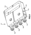
FIG. 3 is a perspective side view of an RJ-45 connector known in the prior art;
FIG. 4A is a perspective of the top plate from the connector array of FIGS. 1A and 1B;
FIG. 4B is a perspective of the bottom plate from the connector array of FIGS. 1A and 1B;
FIG. 4C is a front view of the top plate as shown in FIG. 4A;
FIG. 5A is a front view of two adjacent connector arrays in accordance with an embodiment of the present invention;
FIG. 5B is a front view of two adjacent connector arrays in accordance with another embodiment of the present invention;
FIG. 6 is a perspective of a connector array in accordance with another embodiment of the present invention;
FIG. 7 is a perspective of the top plate from the connector array of FIG. 6;
FIG. 8A is a perspective view of the bottom plate from the connector array of FIG. 6;
FIG. 8B is a top plan view of the bottom plate from the connector array of FIG. 6;
FIG. 9 is a perspective view of a connector array in accordance with another embodiment of the present invention;
FIG. 10A is a perspective view of the body portion from the connector array of FIG. 9;
FIG. 10B is a perspective view of the top plate from the connector array of FIG. 9;
FIG. 10C is a top view of the connector array of FIG. 9 without the top plate installed; and
FIG. 11 is a perspective view of a fiber optic connector;
FIG. 12 is a perspective view of a bottom plate of another embodiment in accordance with the present invention;
FIG. 13A is a cross-sectional view of a connector array in accordance with another embodiment of the present invention;
FIG. 13B is a cross-section of a spring ring;
FIG. 14A is a perspective view of a connector array in accordance with another embodiment of the present invention; and
FIG. 14B is a perspective view of the bottom plate from the connector array of FIG. 14A.
DETAILED DESCRIPTION OF THE PREFERRED EMBODIMENTS
Referring to FIGS. 1A and 1B, connector array 10 in accordance with an embodiment of the present invention is shown. Array 10 has top plate 12, bottom plate 14, mid-section 16, handle 18, and connectors 20, 22, 24, 26, 28, and 30. RJ45 connectors are depicted, however, the skilled artisan will recognize that other connector types, including any electrical or fiber optic connector may be used. Array, as used herein, refers to a plurality of connectors, which ma be as few as two. As shown in FIG. 1A, the connectors of connector array 10 are aligned to be inserted in an array of ports 19.
Referring again to FIGS. 1A and 1B, first and second internal walls 52 a, 54 a, 52 b and 54 b (of top plate 12 and bottom plate 14, respectively), lips 56 a and 56 b (of top plate 12 and bottom plate 14, respectively), walls 38 a and 38 b (of mid-section 16), top plate 12, bottom plate 14 confine each of the four sides of the connectors, thereby holding the connectors in a predefined spacial array as more thoroughly described below.
Referring to FIGS. 2A, 2B and 2C, mid-section 16 has handle 18 connected to and preferably integral with plate 32. Plate 32 has top side 34 and bottom side 36, which are mirror images of each other. Top side 34 has wall 38, post 40 and pegs 42, 44, and 46. Bottom side 36 has thee mirror image of each of these items. However, a skilled artisan will recognize that the configuration of the ports being tested will dictate how the various dimensional features of the present invention will be configured. For example, the pegs may be staggered relative to each other from top to bottom, or they may be staggered relative to front edge 33 of plate 32, forming an angled row of pegs. Width A of pegs 42, 44, and 46 is configured to snugly fit into width B of crimp slot 48 of connector 50 (best shown in FIG. 3). Length C of pegs 42 and 44, and length C′ of peg 46 are configured to fit at least snugly into length D of crimp slot 48 (FIG. 3), but may be smaller. Length C′ of peg 46 is preferably smaller than length D of crimp slot 48 to reduce the tolerances required during manufacturing. In this manner a connector can be press fit onto pegs 42, 44, and 46, such that the connector will not appreciably rotate or move in the z-direction (FIG. 1A) and such that connectors 20, 22, 24, 26, 28 and 30 may be moved into a predetermined spacing in the assembled array. The skilled artisan will readily recognize that the pegs may be indents to receive a protruding feature of a connector.
Referring to FIGS. 4A, 4B and 4C, top plate 12 has first internal wall 52 a, second internal wall 54 a and lip 56 a. Bottom plate 14, being the mirror image of top plate 12, has first internal wall 52 b, second internal wall 54 b, and lip 56 b. Notch 58 a and notch 58 b are configured to fit over post 40 of mid-section 16, and gaps 60, and holes 62 and 63 are provided to permit a bolt to pass therethrough (not shown). Referring to FIG. 4C, distance E between first and second internal walls 52, 54, distance E′ between first internal wall 52 and lip 56, and distance E″ between second internal wall 54 and outer edge 64 are all approximately the width F (FIG. 3) of the back of connector 66. Width G of first and second internal walls 52, 54 is set in accordance with the desired spacing between each connector. Height H of first and second internal walls 52 and 54 is approximately equal to height I (FIG. 3) of back 66 of a connector 50. Height J of lip 56 (FIG. 4C) mand height J′ (FIG. 2C) of wall 38 are preferably less than height I the of back of connector 66. Width K of lip 56, and width K′ of wall 38 are preferably slightly less than the width G of internal walls 52 and 54 to permit adjacent placement of two arrays in a piece of equipment having many ports, as shown in FIG. 5A. A skilled artisan will recognize that these relative heights and distances may vary to achieve the specific dimensions and characteristics of the desired connector array in accordance with the present invention.
Referring to FIGS. 1A and 1B, connector array 10 is assembled by placing six connectors (each pair typically wired together forming a loop-back connector; however, connections to more distant connectors or to connectors on other equipment also may be made) on the pegs as described above (three on each side of mid-section 16). Bottom plate 14 is installed such that first and second internal walls 52 b, 54 b slide between middle connector 22 and outside connectors 20 and 24, and such that lip 56 b abuts against outside connector 20. The outer portion of outside connector 24 is approximately flush with edge 68 b of bottom plate 14; however, the outer portion of this connector abuts against wall 38 b, as described above. Top plate 12 is then installed in the same fashion to the top side 34 of mid-section 16. The connector array is fastened together by bolts (not shown) inserted into holes 62 of top plate 12, through gaps 60 of first and second internal walls 52, 54, and threaded into holes 63 of bottom plate 14.
In the assembled connector array 10 first and second internal walls 52 a, 54 a, 52 b and 54 b abut against the connector that is adjacent on either side of the internal walls, lip 56 a and 56 b abut against the outer portion of outside connectors 20 and 26 (FIG. 1B), walls 38 a and 38 b abut against the outer portion of outside connectors 24 and 30, top and bottom plates 12, 14 abut the top portion of the connectors. This configuration confines each of the four sides of the connectors, preventing appreciable movement in the x- or y-direction. Additionally, pegs 42, 44, and 46 prevent appreciable movement of the connectors in the z-direction.
Referring to FIGS. 1A, 1B, and 5A, lips 56 a and 56 b (of top and bottom plates 12 and 14 respectively) overhang edges 68 a and 68 b (of top and bottom plates 12 and 14 respectively) by approximately width K. Walls 38 a and 38 b (of mid-section 16) hangover edges 64 a and 64 b (of top and bottom plates 12 and 14 respectively) by approximately width K′. Thus, lips 56 a and 56 b and walls 38 a and 38 b define an interlocking feature, as depicted in FIG. 5A, which permits placement of adjacent arrays into a piece of equipment.
Referring to FIG. 6, connector array 10′ in accordance with another embodiment of the present invention is depicted. Connector array 10′ has top plate 70, handle 72, bottom plate 74, and connectors 77, 79, 81, and 83 aligned in a single row. The skilled artisan, will recognize that the row may be staggered aligning the connectors along an angle.
Referring to FIG. 7, top plate 70 has handle 72(preferably integrally formed thereto), side wall 75 and four pegs 76, 78, 80 and 82, which are configured to snugly fit into crimp slot 48 of an RJ-type connector (FIG. 3). Holes 86 are provided to receive two bolts (not shown).
Referring to FIG. 8A and 8B, bottom plate 74 has center wall 88, two outside walls 90 and 92, and lip 94. Guards 96 are provided to keep wire or cable clear of the holes 98 when assembling connector array 10′. Center wall 88 preferably spans the entire width of bottom plate 74, however, it need only span a sufficient distance to prevent the connectors from moving out of a substantially aligned position when the array is fully assembled, as will be appreciated by the skilled artisan. Outside walls 90 and 92 span only a fraction of the width of bottom plate 74 to allow the bolts to pass through bottom plate 74. Similar to connector array 10 described above, the width of center wall 88 and both outside walls 90 and 92 are set to maintain a predetermined distance between the connectors in the assembled array. Similar to the embodiment described above, the width of lip 94 of bottom plate and side wall 75 of top plate 70 are preferably slightly less than the width of the internal walls, thereby permitting adjacent placement of two connector arrays, as shown in FIG. 5B.
Referring to FIG. 6, connector array 10′ is assembled by placing four connectors on the pegs, as described above. Bottom plate 74 is installed such that center wall 88, and outside walls 90 and 92 slide between and abut connectors 77, 79, 81 and 83, and such that lip 94 abuts against outside connector 83, and side wall 75 of top plate 70 abuts against the other outside connecter 77 (not shown). The outer portion of outside connector 83 is approximately flush with edge 100 of top plate 70, and the outside portion of outside connector 77 is approximately flush with edge 102 of bottom plate 74 to provide clearance when two adjacent arrays are used. The connector array is fastened together by bolts (not shown) inserted into holes 86 of top plate 70, through guards 96 and threaded into holes 98 of bottom plate. This configuration, as described above, confines each of the four sides of the connectors, preventing any appreciable movement in the x- or y-direction. Additionally, pegs 76, 78, 80, and 82 prevent any appreciable movement of the connectors in the z-direction.
The connector arrays described above have connectors held snugly in a predetermined spacial arrangement. However, the connectors do not necessarily need to be held snugly in the array, but may be “free floating” within a set tolerance range. For example, reducing the thickness of the walls between the connectors, slightly increasing the height of these walls (thereby ensuring clearance between the plates and the connectors), and/or slightly reducing the width and/or length of the pegs permits the connectors to have limited free movement at least in the x-, y- and/or z-directions, and/or rotationally about any of these axes, thereby creating an array of “free floating” connectors. The free movement described above reduces the tolerance requirements for the structural components of the array, while maintaining the required spacial arrangement of the connectors within the array. The reduction in tolerance requirements permits the construction of much larger arrays, for example eight or more connectors, because cumulative tolerance errors are reduced. A small amount of play is not detrimental to alignment because the front end of the connectors and/or the openings of the ports help guide the connectors when being inserted. Additionally, the movement permits errors in the spacing of the ports to be tested. Thus, a small amount of movement permits self-alignment, reduces the tolerances required for the manufactured parts of the arrays, and reduces the tolerances required in the equipment being tested.
Referring to FIG. 9, connector array 10″ is an array of fiber optic connectors 104, 106, 108 and 110 in accordance with another embodiment of the present invention. In this particular example MTRJ-type connectors are depicted, however other types may be used without exceeding the scope of the present invention, including without limitation SC-type and LC-type connectors. Connector array 10″ has handle 112, top plate 114, and body portion 116. Handle 112 and body portion 116 are connected to and preferably integral with each other.
Referring to FIGS. 10A, 10B and 10C, body portion 116 has four notches 118, 120, 122, and 124 where each notch is separated by a pair of parallel walls 126, 128, and 130. Each of the parallel walls form grooves 132, 134 and 136, which grooves are substantially aligned with each other. Peripheral wall 138 of body portion 116 has two grooves 140 and 142, which grooves substantially align with grooves 132, 134, and 136. Top plate 114 has peripheral wall 144 having two notches 146 and 148 therein, which notches are configured to align over grooves 140 and 142 in peripheral wall 138 of body portion 116, when connector array 10″ is assembled.
Referring to FIG. 11, fiber optic connector 150 has rectangular body 152 with width L and height M, and ridge 154 at one end of the connector. Ridge 154 has a slightly larger width N and height O than rectangular body 152, and has a thickness P. Width Q (FIG. 10C) and height R (FIG. 10A) of notches 118, 120, 122, and 124 are slightly larger than width L and height M of rectangular body 152 of connector 150, respectively, and slightly smaller than width N and height O of ridge 154 of connector 150, respectively. Grooves 132, 134, 136, 140 and 142 all have approximately the same thickness S (FIG. 10C) that is slightly larger than thickness P of ridge 154.
Referring to FIG. 9, to assemble connector array 10″ a connector is inserted into a notch such that ridge 154 of the connector extends partially into the two grooves adjacent to the notch. The parallel walls, or the peripheral wall 138 of body portion 116 permit a slight amount of play in the x- y- and z-directions and a slight amount of rotation about each of these axes, but prevents the connector from sliding out of place. After each of the connectors has been inserted, top plate 114 is placed over body portion 116, such that notches 146 and 148 of peripheral wall 144 substantially align with grooves 140 and 142. Top plate 114 encloses the connectors, such that they may freely float in the x- y- and z-directions without permitting the connectors to slide out of place, however, the connectors may be made snug, as in previously described embodiments, without exceeding the scope of the present invention. As described above, an array of free floating connectors reduces the tolerance requirements for the structural components of the array, while maintaining the required spacial arrangement of the connectors within the array. Additionally, as with other embodiments described herein, top plate 114 and body portion 116 preferably form an enclosure to protect the cables attached to the connectors. This prevents the cables, whether fiber optic or electrical, from being inadvertently damaged during use of the array or equipment into which the array is inserted.
The skilled artisan will also readily recognize that other configurations of this embodiment will fall within the scope of the invention. For example referring to FIG. 12, top plate (not shown) and bottom plate 200 are mirror images of each other. Groove 202 is configured to receive ridge 154 (FIG. 11) of the connector and notch 204 is provided to receive rectangular body 152 of the connector. The top plate (not shown) with mirroring features is secured to bottom plate 200, thereby enclosing a ridge 154 in groove 202. A skilled artisan will recognize that by appropriately dimensioning groove 202 and notch 204 the top plate need only be a flat piece of material.
The present invention may be configured for an array of co-axial cable connectors. For example, referring to FIG. 13A, an array of co-axial connectors 206, in accordance with another embodiment of the present invention, having a co-axial wire extending therein is provided. The connectors each have a spring ring 208 (FIG. 13B) contained within groove 210. Spring ring 208 may expand outward within groove 210. In operation of each co-axial connector in the array is slid over a corresponding female slot in an array of female slots. Rim 212 of a female slot 214 is slightly wider in diameter than the inner diameter of spring ring 208, and will expand the ring when passed therethrough, after which rim 212 will abut against spring ring 208 preventing the inadvertent separation of the array from the array of female slots. The skilled artisan will recognize that rim 212 may be any extension including without limitation the posts of a bayonet fitting.
Referring to FIG. 14A, array 10′″ has bottom plate 215 and top plate 225 configured to receive SC-type fiber optic connectors, in accordance with another embodiment of the present invention. Referring to FIG. 14B, in this embodiment the connector has two ridges 216 and 218 spaced apart by a rectangular portion of the body 220. Ridge 216 abuts against center wall 222 and lower abutment 224. Ridge 218 abuts against outer abutment 224. Alleyways 226 and 228 receive the cylindrical portion of the connectors. Top plate 225 has mirroring features except preferably does not have tab receiving slot 230, as the top portion of the connector does not have a tab 232 (FIG. 14B). When assembled, array 10′″ has multiple SC-type connectors, either free floating or snug, held in an array. A second tab 233 of the connector prevents the over insertion of the connector into a receiving port (not shown). The skilled artisan will recognize that the structure may be expanded to hold more than two connectors.
Referring to FIG. 1A, 6 and 9, as an option one or two clips 156 may be sandwiched between the top and/or bottom plates in these or any embodiments. Clips 156 bias into the slots used to accept the normal barb latch of the prior art connectors. Preferably the barb latch, to the extent one is present, is entirely removed from each of the connectors. In a “free floating” array clips 156 should stay sufficiently clear of the connectors so as not to substantially interfere with the movement thereof. When the array of connectors is inserted into the array of ports, portion 157 of clip 156 is biased into an indent (not shown) within the array of ports, which is used to receive the barb latch normally on an off the shelf connector. Clip 156 also may serve to ensure the connectors are inserted into the ports a sufficient distance. The advantage of using clips 156 in accordance to the present invention is that they do not require depression to release the array from the equipment being tested while still securing the arrays thereto. It will be recognized that clips 156 are not absolutely necessary, but are preferred particularly in use with fiber optic connector arrays.
A technician using the connector arrays described above, with snug or “free floating” connectors, with or without a clip, holds the handle, aligns the connectors with the ports of the equipment to be tested, pushes handle to insert the connectors into the ports. After the testing is completed, the technician grabs the handle and pulls to remove connector array from the equipment. The present invention permits single motion installation and single motion removal of multiple connectors. Thus, use of the connector array of the present invention significantly reduces the risk of repetitive motion injury. Additionally “free floating” arrays reduces the manufacturing tolerances, thereby permitting construction of much larger arrays. An additional advantage is that the preferred modularity of the present invention permits replacement of worn parts, reducing the cost to the user of purchasing an entirely new array.
The materials used for the structural components of the present invention may be selected from any structurally rigid material capable of being molded, machined or cast. For example and without limitation, materials may include resins, plastics, metals or any combination thereof. Preferably all of the structural components are machined aluminum. Preferably the bolts are hardened steel and a threaded steel insert is pressed into the lower plate or body to avoid stripping of the softer aluminum. The skilled artisan will recognize that arrays according to the present invention may be molded from a single piece of material, such as in over-molding or insert molding. Preferably the connectors are purchased from any of the many suppliers of metal, copper or fiber optic connectors, although any custom made connector would fall within the scope of the present invention. The skilled artisan will readily recognize that fewer or many more connectors may be used in the arrays described above without exceeding the scope of the present invention.
Although various embodiments of the present invention have been described, the descriptions are intended to be merely illustrative. Thus, it will be apparent to the skilled artisan that modifications may be made to the embodiments as described without departing from the scope of the claims set forth below.

Claims (12)

What is claimed is:
1. A connector array comprising:
a base member retaining at least an N number of substantially identical connectors of the same gender, N being an integer greater than or equal to 2;
all of the N connectors having a first end and a second end, the first end adapted to engage a matching connector of the opposite gender;
the base member also retaining an X number of clips, X being an integer less than N and including one;
wherein one of the X number of clips is a first clip and wherein one of the N connectors is a first connector, the first clip being associated with a first connector at the second end of the first connector.
2. A connector array according to claim 1, wherein the first clip is mounted as a cantilever with the attached end proximate the second end of the first connector and a free end proximate the first end of the first connector.
3. A connector array according to claim 1, wherein all of the N connectors are made of a non-metallic material and the X number of clips are made of a metallic material.
4. A connector array according to claim 1, wherein the first clip is bent towards the first connector.
5. A connector array according to claim 1, wherein the first connector is an electrical connector.
6. A connector array according to claim 1, wherein the first connector is an optical connector.
7. A connector array comprising:
a base member retaining at least an N number of substantially identical connectors of the same gender, N being an integer greater than or equal to 2;
all of the N connectors having a first end and a second end, the first end adapted to engage a matching connector of the opposite gender;
the base member also retaining an X number of clips, X being an integer less than or equal to N and including zero;
wherein one of the X number of clips is a first clip and wherein one of the N connectors is a first connector, the first clip being associated with a first connector at the second end of the first connector.
8. A connector array according to claim 7, wherein the first clip is mounted as a cantilever with the attached end proximate the second end of the first connector and a free end proximate the first end of the first connector.
9. A connector array according to claim 7, wherein all of the N connectors are made of a non-metallic material and the X number of clips are made of a metallic material.
10. A connector array according to claim 7, wherein the first clip is bent towards the first connector.
11. A connector array according to claim 7, wherein the first connector is an electrical connector.
12. A connector array according to claim 7, wherein the first connector is an optical connector.
US09/511,828 1999-02-23 2000-02-23 Connector arrays Expired - Fee Related US6343950B1 (en)

Priority Applications (1)

Application Number Priority Date Filing Date Title
US09/511,828 US6343950B1 (en) 1999-02-23 2000-02-23 Connector arrays

Applications Claiming Priority (2)

Application Number Priority Date Filing Date Title
US12119599P 1999-02-23 1999-02-23
US09/511,828 US6343950B1 (en) 1999-02-23 2000-02-23 Connector arrays

Publications (1)

Publication Number Publication Date
US6343950B1 true US6343950B1 (en) 2002-02-05

Family

ID=26819202

Family Applications (1)

Application Number Title Priority Date Filing Date
US09/511,828 Expired - Fee Related US6343950B1 (en) 1999-02-23 2000-02-23 Connector arrays

Country Status (1)

Country Link
US (1) US6343950B1 (en)

Cited By (34)

* Cited by examiner, † Cited by third party
Publication number Priority date Publication date Assignee Title
US6488546B2 (en) * 2000-10-27 2002-12-03 Sumitomo Wiring Systems, Ltd. Connector
US6547585B2 (en) * 2001-06-15 2003-04-15 Alcatel, Societe Anonyme Cable holder for supporting a plurality of cable connectors
US20030092313A1 (en) * 2001-11-10 2003-05-15 Malte Schlueter Carrier for several cable holders
US20030198029A1 (en) * 2002-04-19 2003-10-23 Optical Communication Products, Inc. Pluggable optical transceiver with push-pull actuator handle
US20040132348A1 (en) * 2001-03-21 2004-07-08 Yaakov Haggay Patch panel
WO2004097989A2 (en) * 2003-04-29 2004-11-11 Carlyle, Inc. Cable connector holders and methods for connecting and disconnecting a plurality of cable connectors
US7033191B1 (en) 2004-12-02 2006-04-25 Optical Communication Products, Inc. Pluggable optical transceiver with sliding actuator
US20060093303A1 (en) * 2004-11-03 2006-05-04 Randy Reagan Fiber drop terminal
US20060153516A1 (en) * 2005-01-13 2006-07-13 Napiorkowski John J Network interface device having integral slack storage compartment
US20060233506A1 (en) * 2005-04-19 2006-10-19 Michael Noonan Fiber breakout with integral connector
US20070020994A1 (en) * 2005-07-19 2007-01-25 Alvarez Bryce K Connector assembly
US20070259560A1 (en) * 2006-01-13 2007-11-08 Allied Telesis Holdings K.K. Secure connection device
US20080069511A1 (en) * 2004-01-27 2008-03-20 Blackwell Chois A Jr Multi-port optical connection terminal
US20080112681A1 (en) * 2004-02-06 2008-05-15 Battey Jennifer A Optical connection closure having at least one connector port
US20080219631A1 (en) * 2007-03-08 2008-09-11 Erik Gronvall Universal bracket for mounting a drop terminal
US20090003224A1 (en) * 2007-06-27 2009-01-01 David Keib T1 turnaround plug test adaptor
US20090054208A1 (en) * 2007-08-20 2009-02-26 Shen Yi Wu Safety device for motorized fitness equipment
US20090074369A1 (en) * 2007-09-19 2009-03-19 Albert Martin Bolton Multi-port optical connection terminal
US20090245630A1 (en) * 2008-03-31 2009-10-01 Konica Minolta Systems Laboratory, Inc. Systems and Methods for Color Data Compression
US20090244601A1 (en) * 2008-03-31 2009-10-01 Konica Minolta Systems Laboratory, Inc. Systems and Methods for Color Data Compression
US20090244633A1 (en) * 2008-03-31 2009-10-01 Konica Minolta Systems Laboratory, Inc. Systems and Methods for Color Data Compression
US7680388B2 (en) 2004-11-03 2010-03-16 Adc Telecommunications, Inc. Methods for configuring and testing fiber drop terminals
US20100227493A1 (en) * 2009-03-06 2010-09-09 Cisco Technology, Inc. Interface connection management using a removable adapter for communications equipment
US20110312203A1 (en) * 2008-12-31 2011-12-22 Jony Liu Switch Pack Assembly for Cable Clusters of Network Switches and the Special Release Tool Assembly Thereof
US8755663B2 (en) 2010-10-28 2014-06-17 Corning Cable Systems Llc Impact resistant fiber optic enclosures and related methods
US8873926B2 (en) 2012-04-26 2014-10-28 Corning Cable Systems Llc Fiber optic enclosures employing clamping assemblies for strain relief of cables, and related assemblies and methods
US8885998B2 (en) 2010-12-09 2014-11-11 Adc Telecommunications, Inc. Splice enclosure arrangement for fiber optic cables
US8915659B2 (en) 2010-05-14 2014-12-23 Adc Telecommunications, Inc. Splice enclosure arrangement for fiber optic cables
US20150056832A1 (en) * 2013-08-26 2015-02-26 Panduit Corp. Patch Cord Plug Organizer
US9069151B2 (en) 2011-10-26 2015-06-30 Corning Cable Systems Llc Composite cable breakout assembly
US9069149B2 (en) 2013-03-15 2015-06-30 Commscope, Inc. Of North Carolina Flexible switch pack
WO2018216725A1 (en) * 2017-05-23 2018-11-29 住友電気工業株式会社 Optical connector
US10677996B2 (en) 2018-03-08 2020-06-09 Sei Optifrontier Co., Ltd. Optical connector, detaching jig, and cap
US20230013300A1 (en) * 2021-07-13 2023-01-19 Dell Products L.P. Inter-device cabling movement system

Citations (10)

* Cited by examiner, † Cited by third party
Publication number Priority date Publication date Assignee Title
US995627A (en) 1910-10-25 1911-06-20 Thomas E Murray Meter-testing cut-out.
US3997234A (en) 1976-02-17 1976-12-14 Amp Incorporated Plug package handle
US4990094A (en) 1987-12-21 1991-02-05 Amp Incorporated Data distribution panel
US5013247A (en) * 1989-10-16 1991-05-07 International Business Machines Corporation Fiber optic connector assembly adapted for providing circuit card charging
US5326279A (en) 1991-12-27 1994-07-05 Sumitomo Wiring Systems Ltd. Combination connector assembly
US5328388A (en) * 1993-05-28 1994-07-12 Yazaki Corporation Modular electrical connector
US5569040A (en) 1991-12-27 1996-10-29 Sumitomo Wiring Systems, Ltd. Combination connector
US5971801A (en) 1996-09-11 1999-10-26 Yazaki Corporation Service plug having a lever mechanism for positioning circuit terminals and short-circuiting terminals
US6095852A (en) * 1998-12-17 2000-08-01 Yazaki North America, Inc. Connector bracket wire shield with connector retention arms
US6190192B1 (en) * 1998-11-12 2001-02-20 Molex Incorporated Configurable interface connector

Patent Citations (10)

* Cited by examiner, † Cited by third party
Publication number Priority date Publication date Assignee Title
US995627A (en) 1910-10-25 1911-06-20 Thomas E Murray Meter-testing cut-out.
US3997234A (en) 1976-02-17 1976-12-14 Amp Incorporated Plug package handle
US4990094A (en) 1987-12-21 1991-02-05 Amp Incorporated Data distribution panel
US5013247A (en) * 1989-10-16 1991-05-07 International Business Machines Corporation Fiber optic connector assembly adapted for providing circuit card charging
US5326279A (en) 1991-12-27 1994-07-05 Sumitomo Wiring Systems Ltd. Combination connector assembly
US5569040A (en) 1991-12-27 1996-10-29 Sumitomo Wiring Systems, Ltd. Combination connector
US5328388A (en) * 1993-05-28 1994-07-12 Yazaki Corporation Modular electrical connector
US5971801A (en) 1996-09-11 1999-10-26 Yazaki Corporation Service plug having a lever mechanism for positioning circuit terminals and short-circuiting terminals
US6190192B1 (en) * 1998-11-12 2001-02-20 Molex Incorporated Configurable interface connector
US6095852A (en) * 1998-12-17 2000-08-01 Yazaki North America, Inc. Connector bracket wire shield with connector retention arms

Non-Patent Citations (1)

* Cited by examiner, † Cited by third party
Title
Unknown manufacturer, "Connectors embedded in resin," date of manufacture unknown. The attorneys of record have a single physical sample of the "Connectors embedded in resin" in their possession. If the Examiner would like to inspect the sample, please notify the attorneys of record.

Cited By (63)

* Cited by examiner, † Cited by third party
Publication number Priority date Publication date Assignee Title
US6488546B2 (en) * 2000-10-27 2002-12-03 Sumitomo Wiring Systems, Ltd. Connector
US7077710B2 (en) * 2001-03-21 2006-07-18 Rit Technologies Ltd. Patch panel
US20040132348A1 (en) * 2001-03-21 2004-07-08 Yaakov Haggay Patch panel
US6547585B2 (en) * 2001-06-15 2003-04-15 Alcatel, Societe Anonyme Cable holder for supporting a plurality of cable connectors
US20030092313A1 (en) * 2001-11-10 2003-05-15 Malte Schlueter Carrier for several cable holders
US6783391B2 (en) * 2001-11-10 2004-08-31 Agilent Technologies, Inc. Carrier for several cable holders
US6885560B2 (en) * 2002-04-19 2005-04-26 Optical Communication Products, Inc. Pluggable optical transceiver with push-pull actuator handle
US20030198029A1 (en) * 2002-04-19 2003-10-23 Optical Communication Products, Inc. Pluggable optical transceiver with push-pull actuator handle
US20040235344A1 (en) * 2003-04-29 2004-11-25 Kleeberger Terry M. Cable connector holders and methods for connecting and disconnecting a plurality of cable connectors
US6857900B2 (en) * 2003-04-29 2005-02-22 Carlyle, Inc. Cable connector holders and methods for connecting and disconnecting a plurality of cable connectors
WO2004097989A3 (en) * 2003-04-29 2005-02-24 Carlyle Inc Cable connector holders and methods for connecting and disconnecting a plurality of cable connectors
WO2004097989A2 (en) * 2003-04-29 2004-11-11 Carlyle, Inc. Cable connector holders and methods for connecting and disconnecting a plurality of cable connectors
US7653282B2 (en) 2004-01-27 2010-01-26 Corning Cable Systems Llc Multi-port optical connection terminal
US20080069511A1 (en) * 2004-01-27 2008-03-20 Blackwell Chois A Jr Multi-port optical connection terminal
US20080112681A1 (en) * 2004-02-06 2008-05-15 Battey Jennifer A Optical connection closure having at least one connector port
US20100284662A1 (en) * 2004-11-03 2010-11-11 Adc Telecommunications, Inc. Fiber drop terminal
US10042136B2 (en) 2004-11-03 2018-08-07 Commscope Technologies Llc Fiber drop terminal
US20090148120A1 (en) * 2004-11-03 2009-06-11 Adc Telecommunications, Inc. Fiber drop terminal
US7805044B2 (en) 2004-11-03 2010-09-28 Adc Telecommunications, Inc. Fiber drop terminal
US20060093303A1 (en) * 2004-11-03 2006-05-04 Randy Reagan Fiber drop terminal
US10890729B2 (en) 2004-11-03 2021-01-12 Commscope Technologies Llc Fiber drop terminal and bracket
US7680388B2 (en) 2004-11-03 2010-03-16 Adc Telecommunications, Inc. Methods for configuring and testing fiber drop terminals
US20080138025A1 (en) * 2004-11-03 2008-06-12 Fiber Optics Network Solutions Corporation Fiber Drop Terminal
US9851522B2 (en) 2004-11-03 2017-12-26 Commscope Technologies Llc Fiber drop terminal
US11567278B2 (en) 2004-11-03 2023-01-31 Commscope Technologies Llc Fiber drop terminal
US7033191B1 (en) 2004-12-02 2006-04-25 Optical Communication Products, Inc. Pluggable optical transceiver with sliding actuator
US20060153516A1 (en) * 2005-01-13 2006-07-13 Napiorkowski John J Network interface device having integral slack storage compartment
US20060233506A1 (en) * 2005-04-19 2006-10-19 Michael Noonan Fiber breakout with integral connector
US20100014824A1 (en) * 2005-04-19 2010-01-21 Adc Telecommunications, Inc. Loop back plug and method
US8041178B2 (en) 2005-04-19 2011-10-18 Adc Telecommunications, Inc. Loop back plug and method
US20060257092A1 (en) * 2005-04-19 2006-11-16 Yu Lu Loop back plug and method
US11347008B2 (en) 2005-04-19 2022-05-31 Commscope Technologies Llc Fiber optic connection device with ruggedized tethers
US7381087B2 (en) 2005-07-19 2008-06-03 Realm Communications Group Connector assembly
US20070020994A1 (en) * 2005-07-19 2007-01-25 Alvarez Bryce K Connector assembly
US7374447B2 (en) * 2006-01-13 2008-05-20 Allied Telesis Holding K.K. Secure connection device
US20070259560A1 (en) * 2006-01-13 2007-11-08 Allied Telesis Holdings K.K. Secure connection device
US20080219631A1 (en) * 2007-03-08 2008-09-11 Erik Gronvall Universal bracket for mounting a drop terminal
US7748987B2 (en) * 2007-06-27 2010-07-06 Aspect Software, Inc. Method and apparatus for performing turnaround testing on a digital signal 1 board
US20090003224A1 (en) * 2007-06-27 2009-01-01 David Keib T1 turnaround plug test adaptor
US20090054208A1 (en) * 2007-08-20 2009-02-26 Shen Yi Wu Safety device for motorized fitness equipment
US20090074369A1 (en) * 2007-09-19 2009-03-19 Albert Martin Bolton Multi-port optical connection terminal
US7740409B2 (en) 2007-09-19 2010-06-22 Corning Cable Systems Llc Multi-port optical connection terminal
US20090244601A1 (en) * 2008-03-31 2009-10-01 Konica Minolta Systems Laboratory, Inc. Systems and Methods for Color Data Compression
US20090245630A1 (en) * 2008-03-31 2009-10-01 Konica Minolta Systems Laboratory, Inc. Systems and Methods for Color Data Compression
US20090244633A1 (en) * 2008-03-31 2009-10-01 Konica Minolta Systems Laboratory, Inc. Systems and Methods for Color Data Compression
US20110312203A1 (en) * 2008-12-31 2011-12-22 Jony Liu Switch Pack Assembly for Cable Clusters of Network Switches and the Special Release Tool Assembly Thereof
US20100227493A1 (en) * 2009-03-06 2010-09-09 Cisco Technology, Inc. Interface connection management using a removable adapter for communications equipment
US7976346B2 (en) 2009-03-06 2011-07-12 Cisco Technology, Inc. Interface connection management using a removable adapter for communications equipment
US9798085B2 (en) 2010-05-14 2017-10-24 Commscope Technologies Llc Splice enclosure arrangement for fiber optic cables
US8915659B2 (en) 2010-05-14 2014-12-23 Adc Telecommunications, Inc. Splice enclosure arrangement for fiber optic cables
US8755663B2 (en) 2010-10-28 2014-06-17 Corning Cable Systems Llc Impact resistant fiber optic enclosures and related methods
US8885998B2 (en) 2010-12-09 2014-11-11 Adc Telecommunications, Inc. Splice enclosure arrangement for fiber optic cables
US9069151B2 (en) 2011-10-26 2015-06-30 Corning Cable Systems Llc Composite cable breakout assembly
US8873926B2 (en) 2012-04-26 2014-10-28 Corning Cable Systems Llc Fiber optic enclosures employing clamping assemblies for strain relief of cables, and related assemblies and methods
US9069149B2 (en) 2013-03-15 2015-06-30 Commscope, Inc. Of North Carolina Flexible switch pack
US9705250B2 (en) * 2013-08-26 2017-07-11 Panduit Corp. Patch cord plug organizer
US9293862B2 (en) * 2013-08-26 2016-03-22 Panduit Corp. Patch cord plug organizer
US20150056832A1 (en) * 2013-08-26 2015-02-26 Panduit Corp. Patch Cord Plug Organizer
WO2018216725A1 (en) * 2017-05-23 2018-11-29 住友電気工業株式会社 Optical connector
US11156787B2 (en) 2017-05-23 2021-10-26 Sumitomo Electric Industries, Ltd. Optical connector
US10677996B2 (en) 2018-03-08 2020-06-09 Sei Optifrontier Co., Ltd. Optical connector, detaching jig, and cap
US20230013300A1 (en) * 2021-07-13 2023-01-19 Dell Products L.P. Inter-device cabling movement system
US11677205B2 (en) * 2021-07-13 2023-06-13 Dell Products L.P. Method for moving cables between devices

Similar Documents

Publication Publication Date Title
US6343950B1 (en) Connector arrays
US6434316B1 (en) Fiber optic connector
US6623173B1 (en) Fiber optic connector
US8600208B2 (en) Fiber optic telecommunications module
US5367595A (en) Fiber optic connector for connecting a fiber optic harness to an optical device
US20180364434A1 (en) Fiber optic module and system including rear connectors
AU2006276202B2 (en) Fiber optic adapter module
EP0610676B1 (en) Optical fiber coupling device and optoelectronic system utilizing same
US6682228B2 (en) Connector housing for fiber-optic module
US8346047B2 (en) Fiber management component
DE60315433T2 (en) CABLE MANAGEMENT SYSTEM FOR FIBER OPTICAL CONNECTOR ASSEMBLY
AU652111B2 (en) Communication box assembly
CN102971653B (en) Fiber optic module and chassis
US7787737B2 (en) Fiber optic dust cap assembly and method
JPS63291373A (en) Elastic latch and assembly for electric connector and its system
US6434315B1 (en) Fiber optic connector
US6273752B1 (en) Modular connector panel
DE19533296C2 (en) Fastening device for optical fibers
US20140003772A1 (en) Dust caps, fiber optic connectors, and fiber optic splitter modules incorporating interlocking key features
US11385428B2 (en) Cassette assembly for a plural of fiber optic receptacles
US6582133B2 (en) Module and method for interconnecting optoelectronic cards
US9423571B2 (en) Optical connector protecting cap, optical fiber cable with connector cap, and cap removal tool
US6840681B2 (en) Tandem type optical connector
US6512179B1 (en) Transmission cable strain relief device
KR200144731Y1 (en) Connector assembly for multi-core optical cable

Legal Events

Date Code Title Description
FPAY Fee payment

Year of fee payment: 4

REMI Maintenance fee reminder mailed
FEPP Fee payment procedure

Free format text: PETITION RELATED TO MAINTENANCE FEES GRANTED (ORIGINAL EVENT CODE: PMFG); ENTITY STATUS OF PATENT OWNER: SMALL ENTITY

Free format text: PETITION RELATED TO MAINTENANCE FEES FILED (ORIGINAL EVENT CODE: PMFP); ENTITY STATUS OF PATENT OWNER: SMALL ENTITY

REIN Reinstatement after maintenance fee payment confirmed
FP Lapsed due to failure to pay maintenance fee

Effective date: 20100205

PRDP Patent reinstated due to the acceptance of a late maintenance fee

Effective date: 20101014

FPAY Fee payment

Year of fee payment: 8

SULP Surcharge for late payment
REMI Maintenance fee reminder mailed
LAPS Lapse for failure to pay maintenance fees
STCH Information on status: patent discontinuation

Free format text: PATENT EXPIRED DUE TO NONPAYMENT OF MAINTENANCE FEES UNDER 37 CFR 1.362

FP Lapsed due to failure to pay maintenance fee

Effective date: 20140205