US6343978B1 - Method and apparatus for polishing workpiece - Google Patents
Method and apparatus for polishing workpiece Download PDFInfo
- Publication number
- US6343978B1 US6343978B1 US09/566,624 US56662400A US6343978B1 US 6343978 B1 US6343978 B1 US 6343978B1 US 56662400 A US56662400 A US 56662400A US 6343978 B1 US6343978 B1 US 6343978B1
- Authority
- US
- United States
- Prior art keywords
- polishing
- workpiece
- processing
- translational motion
- motion
- Prior art date
- Legal status (The legal status is an assumption and is not a legal conclusion. Google has not performed a legal analysis and makes no representation as to the accuracy of the status listed.)
- Expired - Fee Related
Links
- 238000005498 polishing Methods 0.000 title claims abstract description 389
- 238000000034 method Methods 0.000 title claims description 53
- 230000033001 locomotion Effects 0.000 claims abstract description 125
- 238000012545 processing Methods 0.000 claims abstract description 106
- 239000004744 fabric Substances 0.000 claims abstract description 104
- 238000003825 pressing Methods 0.000 claims abstract description 30
- 238000004140 cleaning Methods 0.000 claims description 63
- 239000006061 abrasive grain Substances 0.000 claims description 27
- 239000011230 binding agent Substances 0.000 claims description 9
- 239000004065 semiconductor Substances 0.000 abstract description 27
- 238000007517 polishing process Methods 0.000 description 39
- 235000012431 wafers Nutrition 0.000 description 24
- 239000002245 particle Substances 0.000 description 22
- 239000000463 material Substances 0.000 description 20
- 230000008569 process Effects 0.000 description 13
- 239000002002 slurry Substances 0.000 description 11
- 239000000126 substance Substances 0.000 description 10
- 230000003746 surface roughness Effects 0.000 description 9
- XLYOFNOQVPJJNP-UHFFFAOYSA-N water Chemical compound O XLYOFNOQVPJJNP-UHFFFAOYSA-N 0.000 description 9
- 238000005201 scrubbing Methods 0.000 description 8
- 230000008901 benefit Effects 0.000 description 7
- 238000013519 translation Methods 0.000 description 7
- 239000000758 substrate Substances 0.000 description 6
- 230000009471 action Effects 0.000 description 5
- 238000013461 design Methods 0.000 description 5
- 238000004519 manufacturing process Methods 0.000 description 4
- 230000007246 mechanism Effects 0.000 description 4
- 239000011859 microparticle Substances 0.000 description 4
- 230000002093 peripheral effect Effects 0.000 description 4
- 230000002411 adverse Effects 0.000 description 3
- 230000000694 effects Effects 0.000 description 3
- 239000011521 glass Substances 0.000 description 3
- 238000009434 installation Methods 0.000 description 3
- 239000004973 liquid crystal related substance Substances 0.000 description 3
- 238000012986 modification Methods 0.000 description 3
- 230000004048 modification Effects 0.000 description 3
- 239000004372 Polyvinyl alcohol Substances 0.000 description 2
- CETPSERCERDGAM-UHFFFAOYSA-N ceric oxide Chemical compound O=[Ce]=O CETPSERCERDGAM-UHFFFAOYSA-N 0.000 description 2
- 229910000422 cerium(IV) oxide Inorganic materials 0.000 description 2
- 238000004891 communication Methods 0.000 description 2
- 239000008367 deionised water Substances 0.000 description 2
- 229910021641 deionized water Inorganic materials 0.000 description 2
- 238000006073 displacement reaction Methods 0.000 description 2
- 239000000428 dust Substances 0.000 description 2
- 239000000835 fiber Substances 0.000 description 2
- 229920002635 polyurethane Polymers 0.000 description 2
- 239000004814 polyurethane Substances 0.000 description 2
- 229920002451 polyvinyl alcohol Polymers 0.000 description 2
- 229920001410 Microfiber Polymers 0.000 description 1
- 239000004677 Nylon Substances 0.000 description 1
- 238000013459 approach Methods 0.000 description 1
- 230000008859 change Effects 0.000 description 1
- 230000002925 chemical effect Effects 0.000 description 1
- 230000003749 cleanliness Effects 0.000 description 1
- 230000002542 deteriorative effect Effects 0.000 description 1
- 230000026058 directional locomotion Effects 0.000 description 1
- 229920001971 elastomer Polymers 0.000 description 1
- 239000012530 fluid Substances 0.000 description 1
- 238000009499 grossing Methods 0.000 description 1
- 239000007788 liquid Substances 0.000 description 1
- 210000000050 mohair Anatomy 0.000 description 1
- 229920001778 nylon Polymers 0.000 description 1
- 229920000728 polyester Polymers 0.000 description 1
- 230000002035 prolonged effect Effects 0.000 description 1
- 239000008213 purified water Substances 0.000 description 1
- 239000011347 resin Substances 0.000 description 1
- 229920005989 resin Polymers 0.000 description 1
- 230000000717 retained effect Effects 0.000 description 1
- 235000019592 roughness Nutrition 0.000 description 1
- 231100000241 scar Toxicity 0.000 description 1
- 238000003860 storage Methods 0.000 description 1
- 229920002803 thermoplastic polyurethane Polymers 0.000 description 1
- 239000011882 ultra-fine particle Substances 0.000 description 1
Images


Classifications
-
- B08B1/32—
-
- B—PERFORMING OPERATIONS; TRANSPORTING
- B24—GRINDING; POLISHING
- B24B—MACHINES, DEVICES, OR PROCESSES FOR GRINDING OR POLISHING; DRESSING OR CONDITIONING OF ABRADING SURFACES; FEEDING OF GRINDING, POLISHING, OR LAPPING AGENTS
- B24B37/00—Lapping machines or devices; Accessories
- B24B37/04—Lapping machines or devices; Accessories designed for working plane surfaces
- B24B37/042—Lapping machines or devices; Accessories designed for working plane surfaces operating processes therefor
-
- B—PERFORMING OPERATIONS; TRANSPORTING
- B24—GRINDING; POLISHING
- B24B—MACHINES, DEVICES, OR PROCESSES FOR GRINDING OR POLISHING; DRESSING OR CONDITIONING OF ABRADING SURFACES; FEEDING OF GRINDING, POLISHING, OR LAPPING AGENTS
- B24B37/00—Lapping machines or devices; Accessories
- B24B37/04—Lapping machines or devices; Accessories designed for working plane surfaces
- B24B37/07—Lapping machines or devices; Accessories designed for working plane surfaces characterised by the movement of the work or lapping tool
- B24B37/10—Lapping machines or devices; Accessories designed for working plane surfaces characterised by the movement of the work or lapping tool for single side lapping
- B24B37/105—Lapping machines or devices; Accessories designed for working plane surfaces characterised by the movement of the work or lapping tool for single side lapping the workpieces or work carriers being actively moved by a drive, e.g. in a combined rotary and translatory movement
-
- H—ELECTRICITY
- H01—ELECTRIC ELEMENTS
- H01L—SEMICONDUCTOR DEVICES NOT COVERED BY CLASS H10
- H01L21/00—Processes or apparatus adapted for the manufacture or treatment of semiconductor or solid state devices or of parts thereof
- H01L21/67—Apparatus specially adapted for handling semiconductor or electric solid state devices during manufacture or treatment thereof; Apparatus specially adapted for handling wafers during manufacture or treatment of semiconductor or electric solid state devices or components ; Apparatus not specifically provided for elsewhere
- H01L21/67005—Apparatus not specifically provided for elsewhere
- H01L21/67011—Apparatus for manufacture or treatment
- H01L21/67155—Apparatus for manufacturing or treating in a plurality of work-stations
- H01L21/67161—Apparatus for manufacturing or treating in a plurality of work-stations characterized by the layout of the process chambers
- H01L21/67173—Apparatus for manufacturing or treating in a plurality of work-stations characterized by the layout of the process chambers in-line arrangement
-
- H—ELECTRICITY
- H01—ELECTRIC ELEMENTS
- H01L—SEMICONDUCTOR DEVICES NOT COVERED BY CLASS H10
- H01L21/00—Processes or apparatus adapted for the manufacture or treatment of semiconductor or solid state devices or of parts thereof
- H01L21/67—Apparatus specially adapted for handling semiconductor or electric solid state devices during manufacture or treatment thereof; Apparatus specially adapted for handling wafers during manufacture or treatment of semiconductor or electric solid state devices or components ; Apparatus not specifically provided for elsewhere
- H01L21/67005—Apparatus not specifically provided for elsewhere
- H01L21/67011—Apparatus for manufacture or treatment
- H01L21/67155—Apparatus for manufacturing or treating in a plurality of work-stations
- H01L21/67207—Apparatus for manufacturing or treating in a plurality of work-stations comprising a chamber adapted to a particular process
- H01L21/67219—Apparatus for manufacturing or treating in a plurality of work-stations comprising a chamber adapted to a particular process comprising at least one polishing chamber
Definitions
- the present invention relates to a method and an apparatus for polishing a workpiece, and more particularly to a method and an apparatus for polishing a workpiece such as a semiconductor wafer, a glass substrate, or a liquid crystal panel which is required to be highly cleaned.
- the conventional polishing apparatus includes a polishing unit 10 , a loading/unloading unit 21 , a feed robot 22 , and two cleaning machines 23 a , 23 b .
- the polishing unit 10 comprises a turntable 12 with a polishing cloth 11 attached to an upper surface thereof, and a top ring 13 for holding a workpiece 1 such as a semiconductor wafer and pressing the workpiece 1 against the polishing cloth 11 on the turntable 12 .
- the workpiece 1 is supported on the lower surface of the top ring 13 , and pressed by a lifting/lowering cylinder against the polishing cloth 11 on the turntable 12 which is being rotated.
- a polishing solution (abrasive solution) Q is supplied from a polishing solution nozzle 14 onto the polishing cloth 11 and retained by the polishing cloth 11 .
- the lower surface of the workpiece 1 is polished by the polishing cloth 11 while the polishing solution Q is being present between the workpiece 1 and the polishing cloth 11 .
- the turntable 12 and the top ring 13 rotate at respective speeds that are independent of each other.
- the top ring 13 holds the workpiece 1 with its edges being spaced distances “a”, “b” from the center and the circumferential edge of the turntable 12 .
- the workpiece 1 has a diameter “d”.
- the turntable 12 has a diameter “D” which is selected to be at least twice the diameter “d” of the workpiece 1 , as indicated by the following equation:
- the workpiece 1 After having been polished, the workpiece 1 is cleaned in one or more cleaning processes and dried by the cleaning machines 23 a , 23 b , and then housed in a delivery cassette 24 of the loading/unloading unit 21 .
- the workpiece 1 when the workpiece 1 is cleaned, it may be scrubbed by a brush of nylon, mohair or the like, or a sponge of PVA (polyvinyl alcohol).
- the workpiece 1 can be polished efficiently to a flat finish.
- the polished surface of the workpiece 1 tends to have a large surface roughness.
- the conventional polishing apparatus of the type described above has an advantage in that the entire surface of the workpiece is polished uniformly, because the elasticity of the polishing cloth 11 moderates the effects of undulation and bowing in the workpiece.
- a workpiece such as a semiconductor wafer is susceptible to edge wear caused by excessive polishing around the peripheral edge of the wafer.
- it is required to obtain a polished surface having a flatness of less than 1,000 angstroms by removing any micro-protrusions from uneven surfaces of the semiconductor wafer.
- the polishing cloth 11 is unable to meet this requirement because the elasticity of the polishing cloth allows the cloth itself to deform, and the material from recessed regions as well as from protruding regions is removed.
- Another object of the present invention is to provide a compact polishing apparatus to produce a high degree of flatness of a workpiece such as a semiconductor wafer.
- a method for polishing a workpiece comprising polishing a surface of the workpiece by pressing the workpiece against a polishing surface and processing a polished surface of the workpiece by pressing the workpiece against a processing surface.
- the processing surface makes relative translational motion relative to the workpiece.
- an apparatus for polishing a workpiece comprising a polishing unit for polishing a surface of the workpiece by pressing the surface of the workpiece against a polishing surface and a processing unit for processing a polished surface of the workpiece by pressing the workpiece against a processing surface.
- the processing surface makes relative translational motion relative to the workpiece. respective rotational motion. However, it may include a respective rotation of a relatively large period of rotation compared to that of the circulative translation between the two surfaces.
- the trace of translation motion can be a linear translation pattern, a polygonal pattern or an elliptical pattern, but from the practical standpoint of polishing or processing efficiency and mechanical ease, a circular pattern would be optimum. In the circulative translation motion, all the regions of the workpiece are subjected to the same pattern.
- a high removal ratio and a high flatness of the workpiece such as a semiconductor wafer is obtained in the polishing step by subjecting the workpiece to a high speed material removal process with the polishing surface.
- the surface processing is carried out by a processing surface at a slow relative speed to attain a smooth surface of the workpiece, and also any micro-particles which may be adhered to the workpiece are removed.
- the surface of the workpiece is treated with a solution appropriate to the application. That is, in case the processing step comprises a polishing step, abrasive particles are used while purified water or a suitable chemical solution is used in the processing step. In the processing step, abrasive particles are normally not used, and if they are used, a small amount of ultra-fine particles are used, and the pressing pressure of the workpiece against the processing surface is reduced compared to the polishing step.
- a polishing apparatus of the circulatory translational motion type may have a processing surface such as a polishing cloth which is of relatively small dimensions. Then, the relative speed between the surface being polished of a workpiece and a polishing cloth is so small that sufficient polishing speed cannot be achieved for polishing the workpiece.
- the processing surface which makes circulatory translational motion can be used because no large processing speed is required by the processing unit such as a cleaning unit.
- a surface of an abrading plate is used as a polishing surface or a processing surface
- such an apparatus can satisfy a wide range of polishing needs, from rough grinding to finish polishing, by choosing an abrasive grain size, a method of supplying the polishing solution and a rotational seed to suit each work. That is, to perform rough polishing, the abrading surface is made coarser and a relatively high speed and high pressing pressure are used. On the other hand, to perform finish polishing, the abrading surface is made finer and a relatively low speed and low pressing pressure are applied. Removal of micro-particles adhering to the workpiece surface may also be performed during the finish polishing by using a solution appropriate to the purpose.
- abrasive grains are used while for finish polishing, deionized water and solutions may be used.
- Abrading grains are normally not used in finish polishing, but if they are needed, a small amount of ultra-fine micro-grains is used.
- the circulatory translational motion is defined as “a relative motion-between a first surface and a second surface facing the first surface and a non-rotational motion which causes every point on the first surface to describe a substantially identical locus with respect to the second surface.”
- the locus maybe a circle, an ellipse, a polygon, or any other regular shape.
- the circulatory translational motion should preferably be made along a circular path. The circulatory translational motion along the circular path allows the on fronting surfaces to move relative to each other uniformly in different areas thereof.
- the circulatory translational motion of this invention has the same meaning as orbital motion.
- the polishing surface may comprise a surface of a polishing cloth or a surface of an abrading plate.
- the polishing surface may rotate about its rotating axis or make relative translational motion relative to the workpiece.
- the translational motion of the polishing surface may be provided only by moving the polishing surface.
- the processing may comprise polishing of the polished surface of the workpiece or cleaning of the polished surface of the workpiece.
- the processing surface may comprise a surface of a polishing cloth or a surface of a wiping cloth or a surface of an abrading plate.
- the relative translational motion of the processing surface maybe provided only by moving the processing surface is more uniformly polished.
- FIG. 1 is a plan view of a polishing apparatus according to a first embodiment of the present invention
- FIG. 2 is a vertical cross-sectional view of a finish polishing unit of the polishing apparatus shown in FIG. 1;
- FIG. 3A is an enlarged plan view of a support structure on a casing for supporting the edge of a surface plate of the finish polishing unit shown in FIG. 2;
- FIG. 3B is a fragmentary cross-sectional view taken along line A—A of FIG. 3 A.
- FIG. 4 is a perspective view of a modified embodiment of the finish polishing unit
- FIG. 5 is a plan view of a polishing apparatus according to a second embodiment of the present invention.
- FIG. 6 is a vertical cross-sectional view of a cleaning unit of the polishing apparatus shown in FIG. 5;
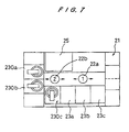
- FIG. 7 is a plan view of a polishing apparatus according to a third embodiment of the polishing apparatus.
- FIG. 8 is a vertical cross-sectional view of a polishing unit of the polishing apparatus shown in FIG. 7;
- FIG. 9 is a perspective view of a conventional polishing apparatus.
- FIG. 10 is a cross-sectional view of a conventional polishing unit of the conventional polishing apparatus shown in FIG. 9 .
- FIGS. 1 through 3A and 3 B Next, a polishing apparatus according to a first embodiment of the present invention will be described with reference to FIGS. 1 through 3A and 3 B.
- a polishing apparatus has a loading/unloading unit 21 positioned at an end of an elongate rectangular space for loading and unloading workpieces 1 (see FIG. 2) such as semiconductor wafers, and a main polishing unit 10 positioned at an opposite end of the elongate rectangular space for polishing the workpieces 1 .
- the loading/unloading unit 21 and the main polishing unit 10 are interconnected by a workpiece delivery line along which two feed robots 22 a , 22 b are movable between the loading/unloading unit 21 and the main polishing unit 10 .
- the polishing apparatus also includes a reversing machine 25 disposed on one side of the workpiece delivery line for reversing the workpieces 1 , a finish polishing unit (second polishing section) 30 and three cleaning units 23 a , 23 b , 23 c disposed on the other side of the workpiece delivery line.
- the cleaning units 23 a , 23 b , and 23 c include rinsing machines or scrubbing machines using brushes, sponges or the like.
- the main polishing unit 10 comprises a turntable 12 and two top rings 13 , and is capable of parallel processing of two workpieces simultaneously. Except for the two top rings 13 , the main polishing unit 10 is basically the same as the polishing unit 10 shown in FIGS. 9 and 10.
- the finish polishing unit 30 will be described below with reference to FIGS. 2 through 3A and 3 B.
- the finish polishing unit 30 comprises a translational table section 31 which provides an abrading surface that makes circulatory translational motion, and a top ring 32 for holding a workpiece 1 with its lower surface facing downwardly and pressing the workpiece 1 against the abrading surface with a given pressure.
- the translational table section 31 comprises a vertical cylindrical casing 34 housing an electric motor 33 therein and having an annular support flange 35 extending radially inwardly from an upper peripheral edge of the casing 34 .
- the support flange 35 has on its upper surface three or more circumferentially spaced support structures 36 which carry a surface plate 37 thereon.
- the surface plate 37 has a plurality of circumferentially equally spaced cavities 38 defined in its lower surface
- the support flange 35 has a plurality of circumferentially equally spaced cavities 39 defined in its upper surface.
- the cavities 38 and the cavities 39 are slightly horizontally displaced from each other for reasons described below.
- the support structures 36 comprise respective upper bearings 40 disposed in the respective cavities 38 and respective lower bearings 41 disposed in the respective cavities 39
- the upper and lower bearings 40 , 41 of each of the support structures 36 are axially interconnected by a cranked joint 44 having upper and lower shafts 42 , 43 that are fitted respectively in the upper and lower bearings 40 , 41 .
- the shafts 42 , 43 and hence the upper and lower bearings 40 , 41 have respective axes horizontally spaced from each other by a distance “e”.
- the surface plate 37 is coupled to the motor 33 as described below. When the motor 33 is energized, the surface plate 37 that is coupled to the motor 33 and supported by the support structures 36 can make translational motion along circles each having a radius which is the same as the distance “e”.
- the surface plate 37 has a tubular member projecting downwardly from the lower surface thereof and defining a recess 48 therein.
- the motor 33 has a vertical shaft 45 having an upper end connected to an eccentric drive shaft 46 that is rotatably mounted in the recess 48 by a bearing 47 .
- the eccentric drive shaft 46 has its central axis Z 2 spaced horizontally from a central axis Z 1 of the shaft 45 by a distance “e”.
- the motor 33 is disposed in a motor chamber 49 that is defined in the casing 34 , and the shaft 45 is rotatably supported in the casing 34 by upper and lower bearings 50 , 51 .
- Balancers 52 a , 52 b are attached respectively to upper and lower ends of the shaft 45 for keeping the shaft 45 in a balanced state while the shaft 45 is rotated in unison with the eccentric drive shaft 46 .
- the surface plate 37 has a diameter which is slightly larger than the sum of the diameter of the workpiece 1 to be polished and the distance “e”.
- the surface plate 37 comprises two plate members 53 , 54 joined to each other with a space 55 defined therebetween for allowing a polishing solution (abrasive liquid) to be supplied to a polishing surface to pass therethrough.
- the space 55 is held in communication with a supply port 56 defined in a side surface of the surface plate 37 and also with a plurality of discharge ports 57 defined in the upper plate member 53 and opening upwardly.
- a polishing cloth 59 is attached to the upper surface of the surface plate 37 , and has a plurality of discharge holes 58 defined therein and aligned in registry with the respective discharge ports 57 .
- the upper surface of the polishing cloth 59 constitutes a polishing surface.
- the discharge ports 57 and the discharge holes 58 are disposed substantially uniformly over the entire surface of the surface plate 37 .
- the polishing cloth 59 may have a grid-like, spiral, or radial pattern of fluid flow grooves defined in the upper surface thereof, and the discharge holes 58 may be held in communication with those grooves.
- the top ring 32 is mounted on the lower end of a shaft 60 so as to allow the top ring 32 to tilt upon changes in the inclination of the polishing surface of the polishing cloth 59 . Downward pressing forces applied by an air cylinder (not shown) and rotative forces from a drive motor (not shown) are transmitted through the shaft 60 to the top ring 32 .
- the top ring 32 is structurally identical to the top ring 13 shown in FIGS. 9 and 10 except that the top ring 32 rotates about its axis at a lower speed.
- the upper end of the casing 34 , the surface plate 37 , and the top ring 32 are horizontally surrounded by a reservoir 61 mounted on the upper end of the casing 34 for collecting a polishing solution that is supplied during polishing.
- a workpiece 1 is delivered by the feed robots 22 a , 22 b through the reversing machine 25 , if necessary, to one of the top rings 13 of the main polishing unit 10 , and is attached to the top ring 13 .
- the top ring 13 rotates about its own axis and presses the workpiece 1 against the polishing cloth 11 (see FIG. 10) on the turntable 12 .
- a first polishing process is carried out by the actions of the high-speed relative movement between the workpiece 1 and the polishing cloth 11 , and of the chemical effects produced by the polishing solution supplied from the polishing solution nozzle 14 (see FIG. 10 ).
- the workpiece 1 is, either directly or after a rough cleaning, transferred to the finish polishing unit 30 where the workpiece 1 is subject to a second polishing process.
- the motor 33 is energized to cause the surface plate 37 to make circulatory translational motion, and the workpiece 1 attached to the top ring 32 is pressed against the upper surface of the polishing cloth 59 that is attached to the surface plate 37 .
- the surface of the polishing cloth 59 constitutes a processing surface.
- the workpiece 1 is then polished by a polishing solution that is supplied to the surface to be polished of the workpiece 1 through the supply port 56 , the space 55 , the discharge ports 57 , and the discharge holes 58 .
- the discharge ports 57 and the discharge holes 58 allow the polishing solution to be supplied at a sufficient rate to the entire area of the workpiece 1 including the central area. Since small relative translational motion along circles having the radius “e” occurs between the polishing cloth 59 and the workpiece 1 , the workpiece 1 is uniformly polished over its entire surface. If the polished surface of the workpiece 1 and the polishing cloth 59 stay in the same relative positional relationship, then the polished surface of the workpiece 1 would be adversely affected by local irregularities of the polishing cloth 59 .
- the top ring 32 is rotated slowly about its own axis so that the surface of the workpiece 1 is not polished by the same local areas of the polishing cloth 59 . Therefore, the surface of the workpiece 1 is polished by successively different areas of the polishing cloth 59 , and hence is more uniformly polished.
- the workpiece 1 and the polishing cloth 11 are moved relatively to each other at a high speed and pressed against each other under relatively large forces.
- the finish polishing unit 30 since minute particles need to be removed from the polished surface of the workpiece 1 while the flatness and surface roughness of the workpiece 1 are also required to be improved, the surface roughness of the polishing cloth 59 is small, and the velocity of relative motion between the workpiece 1 and the polishing cloth 59 and the pressing force of the workpiece 1 against the polishing cloth 59 are smaller than those of the first polishing process.
- the polishing solution is usually pure water, but may be a chemical or a special slurry if necessary.
- a chemical or a special slurry depending on the material of the workpiece 1 may be supplied between the workpiece 1 and the polishing cloth 59 .
- the workpiece 1 is cleaned by the cleaning machines 23 a - 23 c in one or more cleaning processes and then dried, and thereafter accommodated in the delivery cassette 24 .
- the main polishing unit 10 has two top rings 13 . Therefore, if the time required for the second polishing process is reduced to about half the time required for the first polishing process, then the main polishing unit 10 and the finish polishing unit 30 can be operated efficiently without loss of time.
- the diameter of the surface plate 37 may be slightly larger than the diameter of the workpiece 1 by the distance “e”.
- the finish polishing unit 30 makes circulatory translational motion, it is possible to support the surface plate 37 at several locations along the peripheral edges of the surface plate 37 , as shown in FIG. 2, so that the workpiece can be polished to a higher flatness than with the turntable which rotates at a high speed.
- Polishing solution (Abrasive solution): Differs depending on the material of the workpiece
- Polishing cloth Differs depending on the material of the workpiece
- Relative speed 0.07-0.6 m/sec.
- Polishing time Differs depending on the amount of material to be removed by polishing
- Polishing solution Water, a chemical, a slurry
- Polishing cloth Soft cloth (non-woven cloth, nap-like material)
- Relative speed 0.07-0.6 m/sec.
- the workpiece 1 may make circulatory translational motion with respect to the polishing cloth 59 .
- the surface plate 37 is supported using the cranked joints 44 combined with the bearings 40 , 41 .
- the surface plate 37 may be supported by a suitable support structure, such as magnetic bearings or lubrication-free slide bearings, which allow the surface plate 37 to make circulatory translational motion while preventing it from rotating about its own axis.
- the surface plate 37 is caused to make circulatory translational motion by the eccentric drive shaft 46 on the shaft 45 of the motor 33 .
- the surface plate 37 may be moved by a vector sum of motion in an X direction and motion in a Y direction using an X-Y stage, or the polishing cloth 59 and the workpiece 1 may jointly be moved to make circulatory translational motion.
- FIG. 4 shows an embodiment of a polishing apparatus of this type comprising a top ring 100 for holding a workpiece on the lower surface thereof, and a polishing tool 101 arranged beneath the top ring 100 and attached to the X-Y stage.
- an electro-plated grindstone is utilized as a polishing tool of a relatively small abrasive grain size.
- the X-Y stage comprises an X-stage 102 , a Y-stage 103 and a fixing plate 104 which are stacked in the illustrated order and mounted on a base 105 .
- a linear guide mechanism and a linear driving mechanism such as a feed screw so as to make the X-stage 102 movable in the X direction.
- the same mechanisms are provided between the Y-stage 103 and the fixing plate 104 , and a controlling device is provided for controlling these X- and Y- direction driving mechanisms.
- the polishing tool 101 makes circulatory translational motion as in the first embodiment of the invention. It is preferable to rotate the top ring 100 with a period of rotation significantly in excess of a period of the circulatory translational motion of the tool 101 in order to eliminate the effect resulting from a local difference of surface condition of the tool.
- This embodiment since a mechanical “eccentric” design is not used, has an advantage that more degrees of freedom in changing the trace (or locus) of the circulatory translational motion can be obtained. For example, since it is possible to change the diameter of the circulatory translational motion without stopping the operation, the polishing motion during the polishing step of the workpiece can be changed so as to polish the workpiece with a smaller diameter in the starting and terminating periods than in the usual polishing period. By applying such a control method, it can avoid the deteriorative effects caused by the localized conditional differences on the polishing tool surface, such as a unidirectional scar, when repeating a simple circulative motion.
- the structure of this embodiment can create not only circular translational motion but also any other type of circulatory translational motion such as, an ellipsoidal motion, an eight-shape (8) motion or an oscillating spiral motion, or any kind of combination thereof.
- the structure of this embodiment can create not only circulatory motion having a certain trace but also totally random translational motion which is by no means circulatory.
- This intentional randomization of the relative translational motion can be performed by using a random number generation function of a computer processor, for example.
- the polishing process is carried out in two stages, first and second polishing steps, it is possible to produce a high degree of flatness and smoothness of the workpiece.
- the workpiece and the polishing tool are moved relative to each other at relatively high speeds to produce flat surface of the workpiece.
- This is followed by a second step to obtain smooth surface of the workpiece by using a polishing tool having a lesser abrasive quality and providing a relatively small degree of relative motion between the workpiece and the polishing tool.
- the polishing process is completed by removing micro-particles which may adhere to the workpiece, to thus produce a workpiece having a high degree of flatness, smoothness and cleanliness.
- the size of the apparatus can be slightly larger than the workpiece by the distance of eccentricity, thus enabling the apparatus to be compact. Additional benefit is that the drive motor can be small and the occupied floor space is also small.
- the surface plate is supported at three locations or more around the periphery of the surface plate so that the application of the pressing force does not affect the stability of supporting member and the flatness of the polished surface can be maintained.
- a polishing apparatus has a loading/unloading unit 21 positioned at an end of an elongate rectangular space for loading and unloading workpieces 1 (see FIG. 6) such as semiconductor wafers, and a main polishing unit 10 positioned at an opposite end of the elongate rectangular space for polishing the workpieces 1 .
- the loading/unloading unit 21 and the main polishing unit 10 are interconnected by a workpiece delivery line along which two feed robots 22 a , 22 b are movable between the loading/unloading unit 21 and the main polishing unit 10 .
- the polishing apparatus also includes a reversing machine 25 disposed on one side of the workpiece delivery line for reversing the workpieces 1 , a cleaning unit 130 and three cleaning units 23 a , 23 b , 23 c disposed on the other side of the workpiece delivery line.
- the cleaning units 23 a , 23 b , and 23 c include rinsing machines or scrubbing machines using brushes, sponges, or the like.
- the main polishing unit 10 comprises a turntable 12 and two top rings 13 , and is capable of parallel processing of two workpieces simultaneously. Except for the two top rings 13 , the main polishing unit 10 is basically the same as the polishing unit 10 shown in FIGS. 9 and 10.
- the cleaning unit 130 has the same structure as the polishing unit 30 of the first embodiment shown in FIG. 2 .
- the cleaning unit 130 comprises a translational table section 31 which provides an abrading surface that makes circulatory translational motion, and a top ring 32 for holding a workpiece 1 with its lower surface facing downwardly and pressing the workpiece 1 against the abrading surface with a given pressure.
- a cleaning solution is supplied to the surface to be cleaned of the workpiece through the supply port 56 , the space 55 , the discharge ports 57 , and the discharge holes 58 .
- a workpiece 1 is delivered by the feed robots 22 a , 22 b through the reversing machine 25 , if necessary, to one of the top rings 13 of the main polishing unit 10 , and is attached to the top ring 13 .
- the top ring 13 rotates about its own axis and presses the workpiece 1 against the polishing cloth 11 (see FIG. 10) on the turntable 12 .
- the workpiece 1 is polished by the polishing solution Q supplied from the polishing solution nozzle 14 while the workpiece 1 and the polishing cloth 11 are moving relatively to each other at a high speed.
- the workpiece 1 After having been polished by the main polishing unit 10 , the workpiece 1 is, either directly or after a rough cleaning, transferred to the cleaning unit 130 where the workpiece 1 is cleaned. Specifically, the motor 33 is energized to cause the surface plate 37 to make circulatory translational motion, and the workpiece 1 attached to the top ring 32 is pressed against the upper surface of the polishing cloth 59 that is attached to the surface plate 37 .
- the workpiece 1 is then cleaned by a cleaning solution that is supplied to the surface of the workpiece 1 through the supply port 56 , the space 55 , the discharge ports 57 , and the discharge holes 58 .
- the discharge ports 57 and the discharge holes 58 allow the cleaning solution to be supplied at a sufficient rate to the entire area of the workpiece 1 including the central area. Since small relative translational motion along circles having the radius “e” occurs between the polishing cloth 59 and the workpiece 1 , the workpiece 1 is uniformly polished over its entire surface. If the polished surface of the workpiece 1 and the polishing cloth 59 stay in the same relative positional relationship, then the polished surface of the workpiece 1 would be adversely affected by local irregularities of the polishing cloth 59 .
- the top ring 32 is rotated slowly about its own axis so that the surface of the workpiece 1 will not be polished only by local areas of the polishing cloth 59 . Therefore, the surface of the workpiece 1 is polished by successively different areas of the polishing cloth 59 , and hence is more uniformly polished.
- the main polishing unit 10 since the workpiece 1 needs to be polished to a desired surface finish or to be polished in a desired polishing speed, the workpiece 1 and the polishing cloth 59 are moved relatively to each other at a high speed and pressed against each other under relatively large forces for thereby polishing the workpiece 1 to a flat finish, or for thereby polishing the workpiece 1 in a high polishing speed.
- the cleaning solution is usually pure water, but may be a chemical or a special slurry if necessary. For example, a chemical or a special slurry depending on the material of the workpiece 1 may be supplied between the workpiece 1 and the polishing cloth 59 .
- the polishing solution contains abrasive particles.
- the cleaning solution usually does not contain abrasive particles, but may contain fine abrasive particles.
- the workpiece 1 After the workpiece 1 has been cleaned by the cleaning unit 130 , the workpiece 1 is further cleaned by the cleaning machines 23 a - 23 c in one or more cleaning processes and then dried, and thereafter accommodated in the delivery cassette 24 .
- the main polishing unit 10 has two top rings 13 . Therefore, if the time required for the cleaning process is reduced to about half the time required for the polishing process, then the main polishing unit 10 and the cleaning unit 130 can be operated efficiently without loss of time.
- the cleaning unit 130 is of the circulatory translational motion type, the diameter of the surface plate 37 may be slightly larger than the diameter of the workpiece 1 by the distance “e”. Therefore, the motor 33 may be of a relatively small size, and the polishing apparatus may take up a relatively small space.
- the polishing cloth 59 in the cleaning unit 130 does not rotate about its own axis, the relative speed between the workpiece 1 and the polishing cloth 59 remains in the same condition at any position on the workpiece 1 . Therefore, the workpiece 1 can be processed to a flat finish even when it is processed at a low speed, and can advantageously be processed to a smooth surface finish.
- An installation space for the cleaning unit 130 may be comparatively small. Because the surface plate 37 of the cleaning unit 130 makes circulatory translational motion, the surface plate 37 can be supported at a plurality of positions along its circumferential edge, as shown in FIG. 6 . Therefore, even when the surface plate 37 is subjected to large pressing forces, the surface plate 37 can stably be supported, thus allowing the workpiece 1 to be polished to a higher planar finish than with a turntable which rotates at a high speed.
- Polishing solution Differs depending on the material of the workpiece
- Polishing cloth Differs depending on the material of the workpiece
- Relative speed 0.07-0.6 m/sec.
- Polishing time Differs depending on the amount of material to be removed by polishing
- Polishing cloth Soft cloth (non-woven cloth, nap-like material)
- Relative speed 0.07-0.6 m/sec.
- the workpiece 1 may make circulatory translational motion with respect to the polishing cloth 59 .
- the surface plate 37 is caused to make circulatory translational motion by the eccentric drive shaft 46 on the shaft 45 of the motor 33 .
- the surface plate 37 may be moved by a vector sum of motion in an X direction and motion in a Y direction using an X-Y stage, or the polishing cloth 59 and the workpiece 1 may jointly be moved to make circulatory translational motion.
- the surface plate 37 is supported using the cranked joints 44 combined with the bearings 40 , 41 .
- the surface plate 37 may be supported by a suitable support structure, such as magnetic bearings or lubrication-free slide bearings, which allows the surface plate 37 to make circulatory translational motion while preventing it from rotating about its own axis.
- polishing unit including a first abrasive member rotatable about its own axis for polishing a workpiece while the workpiece is being pressed against the first abrasive member under a predetermined pressure
- a cleaning unit including a second abrasive member made of a wiping cloth, a non-woven cloth, or a cloth other than a non-woven cloth for scrubbing the workpiece while being pressed against the polished surface of the workpiece.
- the polishing unit 10 with the two top rings 13 as shown in FIG. 5 may be replaced with the polishing unit 10 with the single top ring 13 as shown in FIG.
- the cleaning unit 130 with the surface plate 37 making circulatory translational motion may be replaced with a cleaning unit with the turntable 12 and the single top ring 13 as shown in FIG. 10 .
- the polishing solution is used in the polishing unit
- the cleaning solution such as water, a chemical or a slurry is used in the cleaning unit
- the relative speed between the workpiece and the abrasive member, the pressure under which the workpiece and the abrasive member are pressed against each other, and the surface roughness of the abrasive member are set to different values in the polishing and cleaning units.
- the second abrasive member in the cleaning unit may comprise a polishing cloth, a wiping cloth, or the like.
- the polishing cloth is generally used to polish semiconductor wafers to a flat mirror finish, and is available on the market.
- the polishing cloth may be a non-woven cloth of polyester, Suba 800 or IC-1000 manufactured by Rodel, Inc., Surfin xxx-5, Surfin 000 manufactured by Fujimi Incorporated.
- the polishing cloths, Suba 800, Surfin xxx-5, and Surfin 000 are made of fibers and put together by an urethane resin, and the polishing cloth IC-1000 is made of foamed polyurethane.
- the foamed polyurethane is porous and has a number of minute recesses on its surface which are considered to be capable of holding particles.
- the polishing cloth is basically used to polish semiconductor wafers and is of such a structure as to attract abrasive particles contained in a polishing solution to its own surface.
- the polishing cloth is effective to easily remove particles that strongly adheres to the semiconductor wafers.
- the cleaning unit uses a polishing cloth that is originally used to polish a semiconductor wafer
- the polishing cloth can reduce the surface roughness of the semiconductor wafer, and hence makes the surface of the semiconductor wafer flat and smooth when the cleaning unit cleans the semiconductor wafer. This effect of the polishing cloth was confirmed by way of experimentation.
- the wiping cloth is made of ultrafine fibers having a diameter ranging from 1 to 2 ⁇ m, and is commercially available as Miracle series (tradename) of Toray, Minimax (tradename) of Kanebo, etc. Since these wiping cloths have 100-200 thousand fibers per one square inch, they have many points of contact with a workpiece to be wiped for thereby removing minute particles from the workpiece.
- the wiping cloth is a thin cloth, it may be attached to the surface plate through a damper of sponge, rubber, or the like so as not to damage the workpiece 1 while cleaning the workpiece 1 .
- the principles of the present invention are applicable to various workpieces including a glass substrate and a liquid crystal panel which need to be highly cleaned.
- the polishing apparatus shown in FIG. 5 may further be modified such that the cleaning units 23 a , 23 b , 23 c such as rinsing machines or scrubbing machines may be positioned adjacent to the polishing unit 10 for removing relatively large particles from the workpiece, and the cleaning unit 130 may be positioned adjacent to the cleaning units 23 a , 23 b , 23 c for removing submicron particles that cannot be removed from the workpiece by a scrubbing action using a brush or a sponge.
- the cleaning units 23 a , 23 b , 23 c such as rinsing machines or scrubbing machines
- the cleaning unit 130 may be positioned adjacent to the cleaning units 23 a , 23 b , 23 c for removing submicron particles that cannot be removed from the workpiece by a scrubbing action using a brush or a sponge.
- a polishing apparatus has a loading/unloading unit 21 positioned at an end of an elongate rectangular space for loading and unloading workpieces 1 (see FIG. 8) such as semiconductor wafers, and two main polishing units 230 a , 230 b positioned at an opposite end of the elongate rectangular space for polishing the workpieces 1 .
- the loading/unloading unit 21 and the main polishing units 230 a , 230 b are interconnected by a workpiece delivery line along which two feed robots 22 a , 22 b are movable between the loading/unloading unit 21 and the main polishing units 230 a , 230 b .
- the polishing apparatus also includes a reversing machine 25 disposed on one side of the workpiece delivery line for reversing the workpieces 1 , a finish polishing unit 230 c and three cleaning units 23 a , 23 b , 23 c disposed on the other side of the workpiece delivery line.
- the cleaning units 23 a , 23 b , 23 c include rinsing machines or scrubbing machines using brushes, sponges, or the like.
- the main polishing units 230 a , 230 b and the finish polishing unit 230 c are basically of the same structure, and are respectively provided with a translational table section 31 which provides circulatory translational motion of the abrading surface of a polishing tool, and a top ring 32 for holding the workpiece 1 to be polished and pressing the workpiece 1 against the abrading surface with a given pressure.
- the main and finish polishing units 230 a , 230 b and 230 c have the same structure as the finish polishing unit 30 of the first embodiment shown in FIG. 2, except for an abrading plate.
- an abrading plate 159 is attached to the top surface of the surface plate 37 of the main polishing units 230 a , 230 b , and a polishing cloth 159 a is attached to the surface plate 37 of the finish polishing unit 230 c .
- the abrading plate 159 and polishing cloth 159 a are also provided with a plurality of discharge holes 58 aligned in registry with the respective discharge ports 57 .
- the discharge ports and holes 57 , 58 are disposed substantially uniformly over the entire surface of the surface plate 37 , the abrading plate 159 and the polishing cloth 159 a .
- the abrading plate 159 is bonded to the top surface of the surface plate 37 in the main polishing units 230 a , 230 b , and the polishing cloth 159 a is bonded to the top surface of the surface plate 37 in the finish polishing unit 230 c.
- the abrading plate 159 is a circular disc made of abrasive grains of less than several micrometers (for example, CeO 2 ) and a resin serving as a binder for the abrasive grains. In order to make the abrading surface flat, the material and manufacturing process are selected so that the abrading plate 159 would not have bowing and deformation during manufacturing and storage.
- the abrading plate 159 has a grid-like, spiral, or radial pattern of grooves defined in the upper surface to distribute the polishing solution and to remove ground-off particles by polishing, and the discharge holes 58 are aligned with the grooves.
- the particle size of the abrasive grains contained in the polishing solution is selected so that the particle size of the abrasive grains is relatively large for the rough polishing units 230 a , 230 b , but is relatively small in the finish polishing unit 230 c.
- the top ring 32 has the same structure as the top ring of the first embodiment shown in FIG. 2 .
- a workpiece 1 is delivered by the feed robots 22 a , 22 b through the reversing machine 25 , if necessary, to one of the top rings 13 of the main polishing units 230 a , 230 b , and is attached to the top ring 13 .
- the main polishing units 230 a or 230 b rough polishing is performed.
- Roughly polished workpiece is transferred by the robot 22 a , 22 b to the cleaning machine 23 a and cleaned therein, and then finish polishing is performed in the finish polishing unit 230 c.
- the surface plate 37 makes circulatory translational motion by the action of the driving motor 33 , and the workpiece 1 attached to the top ring 32 is pressed against the surface of the abrading plate 159 bonded to the surface plate 37 .
- the polishing solution is supplied to the surface to be polished of the workpiece 1 through the supply port 56 , the space 55 , the discharge ports and holes 57 , 58 , and the grooves of the abrading plate 159 .
- the polished surface of the workpiece 1 and the abrading plate 159 stay in the same relative positional relationship, then the polished surface of the workpiece 1 would be adversely affected by local irregularities of the abrading plate 159 .
- the top ring 32 is rotated slowly about its own axis so that the surface of the workpiece 1 is not polished by the same local areas of the abrading plate 159 . Therefore, the surface of the workpiece 1 is polished by successively different areas of the abrading plate 159 , and hence is more uniformly polished.
- Finish polishing is basically the same process as rough polishing.
- polishing conditions are such that the workpiece 1 and the polishing tool (abrading plate) 159 are moved at a relatively fast speed, and that the pressing force is relatively high and the polishing solution contains relatively coarse abrasive grains to produce a given amount of material removal.
- the purpose of the finish polishing process is, in addition to producing further leveling and smoothing of the surface of the workpiece, to remove any adhered micro-particles from the surface of the workpiece. Therefore, roughness of the polishing surface of the polishing tool (cloth) 159 a is finer, and the velocity of relative motion and pressing force between the polishing tool and the workpiece are lower than those in the main polishing process.
- the polishing solution is usually deionized water, but occasionally a chemical or a slurry may be used when necessary. In case of using a slurry, the use of abrasive grains of the same material as the abrading plate in the slurry may produce good polishing results.
- the workpiece 1 is cleaned by the cleaning machines 23 a - 23 c in one or more cleaning processes and then dried, and thereafter accommodated in the delivery cassette 24 .
- two main polishing units 230 a , 230 b are provided to perform the main polishing process while one finish polishing unit 230 c is provided. This is because the duration of the main polishing process is longer than that of the finish polishing process. Thus, the main polishing units and the finish polishing unit can be operated efficiently without a loss time.
- polishing apparatus because the polishing process is carried out in two stages in parallel, particle size of the abrading plate 159 and the supply and discharge ports 57 , 58 can be selected to suit the condition of each polishing process. Therefore, the duration of each polishing process is shortened. Accordingly, the throughput in the overall apparatus is significantly improved compared with the conventional polishing apparatus shown in FIGS. 9 and 10.
- the diameter of the surface plate 37 may be slightly larger than the diameter of the workpiece 1 by the distance “e”. Therefore, compared with the conventional polishing unit 10 , the installation space is reduced significantly. Additionally, it is easier to design a combined layout of units including cleaning machines and inverters as well as to modify an existing layout.
- the surface plate 37 makes circulatory translational motion in the polishing units 230 a - 230 c , the surface plate 37 is supported at several locations along the peripheral edge of the surface plate 37 as shown in FIG. 8, so that the workpiece can be polished to a higher flatness than with the conventional polishing apparatus having a turntable which rotates at a high speed.
- an abrading plate may also be used in the second polishing process.
- abrasive grains of the abrading plate in the second polishing process are finer than those in the first polishing process.
- Polishing solution (Abrasive solution): Differs depending on the material of the workpiece
- Grain size of the abrading plate 0.1-10 ⁇ m
- Relative speed 0.07-0.6 m/sec.
- Polishing time Differs depending on the amount of material to be removed by polishing
- Polishing solution Water, a chemical, a slurry
- Polishing cloth Soft cloth (non-woven cloth, nap-like material)
- Polishing time 10-120 sec.
- the polishing tool makes circulative translation motion
- the workpiece may make the same motion.
- the surface plate 37 is caused to make circulatory translational motion by the eccentric drive shaft 46 on the shaft 45 of the motor 33 .
- the surface plate 37 may be moved by a vector sum of motion in an X direction and motion in a Y direction using an X-Y stage.
- the circular translation motion is produced by an “eccentric” design provided at the end of the drive shaft of the motor, but other designs may be utilized.
- circulative translation motion of the surface plate may be created by the vector sum of motions in the X- and Y-directions using the X-Y stage.
- the polishing tool and the substrate may jointly be moved to make circulatory translational motion.
- crank type of support is utilized to support the surface plate, but it is possible to use other types of support such as magnetic bearings or lubrication-free slide bearings, which allow the surface plate 37 to make circulatory translational motion while preventing it from rotating about its own axis.
- the size of the abrading plate needs to be slightly larger than the workpiece size, it is easy to produce higher flatness over the entire surface of the polishing tool, compared with the conventional large polishing table.
- the polishing apparatus becomes compact and the drives can also be small, and the installation space of the polishing apparatus is minimized.
- the overall design of the polishing apparatus, including the cleaning and reversing machines, is simplified, and the changes of the layout can be made readily.
- the relative speed between the workpiece and the polishing tool is uniform over the entire surface of the workpiece, and hence it is possible to produce flatness of the workpiece even at a low speed and to provide a smooth surface of a superior quality.
Abstract
A workpiece such as a semiconductor wafer is polished by pressing the workpiece against a polishing surface under a predetermined pressure. A polished surface of the workpiece is processed by pressing the workpiece against a processing surface under a predetermined pressure while the processing surface makes circulatory translational motion along a predetermined path. The processing surface comprises a surface of a polishing cloth or a surface of an abrading plate, and the polished surface of the workpiece is further polished or cleaned.
Description
This is a divisional application Ser. No. 09/301,718, filed Apr. 29, 1999, which is a continuation-in-part of application Ser. No. 08/857,252, filed May 16, 1997, now U.S. Pat. No. 5,989,107 of application Ser. No. 08/972,012, filed Nov. 17, 1997, now abandoned and of International Application No. PCT/JP98/05253, filed Nov. 20, 1998.
1. Field of the Invention
The present invention relates to a method and an apparatus for polishing a workpiece, and more particularly to a method and an apparatus for polishing a workpiece such as a semiconductor wafer, a glass substrate, or a liquid crystal panel which is required to be highly cleaned.
2. Description of the Related Art
As semiconductor devices become more highly integrated, circuit interconnections become finer and the distances between those interconnections also become smaller. Photolithographic processes for producing interconnections that are 0.5 μm wide or smaller, particularly, require a flat image-focusing plane for the stepper because the depth between focal points is small. If a dust particle whose size is greater than the distances between the interconnections is present on a semiconductor substrate, then an undesirable short circuit tends to occur between interconnections through the dust particle.
Therefore, it is important that the workpiece processing must produce a flat and clean workpiece. These processing requirements apply equally to other workpiece materials, such as glass substrates for photo-masking or liquid crystal display panels.
One conventional polishing apparatus is shown in FIG. 9 of the accompanying drawings. As shown in FIG. 9, the conventional polishing apparatus includes a polishing unit 10, a loading/unloading unit 21, a feed robot 22, and two cleaning machines 23 a, 23 b. As shown in FIG. 10 of the accompanying drawings, the polishing unit 10 comprises a turntable 12 with a polishing cloth 11 attached to an upper surface thereof, and a top ring 13 for holding a workpiece 1 such as a semiconductor wafer and pressing the workpiece 1 against the polishing cloth 11 on the turntable 12.
In operation, the workpiece 1 is supported on the lower surface of the top ring 13, and pressed by a lifting/lowering cylinder against the polishing cloth 11 on the turntable 12 which is being rotated. A polishing solution (abrasive solution) Q is supplied from a polishing solution nozzle 14 onto the polishing cloth 11 and retained by the polishing cloth 11. The lower surface of the workpiece 1 is polished by the polishing cloth 11 while the polishing solution Q is being present between the workpiece 1 and the polishing cloth 11.
The turntable 12 and the top ring 13 rotate at respective speeds that are independent of each other. The top ring 13 holds the workpiece 1 with its edges being spaced distances “a”, “b” from the center and the circumferential edge of the turntable 12. Thus, the entire lower surface of the workpiece 1 is uniformly polished at a high polishing rate. The workpiece 1 has a diameter “d”. The turntable 12 has a diameter “D” which is selected to be at least twice the diameter “d” of the workpiece 1, as indicated by the following equation:
After having been polished, the workpiece 1 is cleaned in one or more cleaning processes and dried by the cleaning machines 23 a, 23 b, and then housed in a delivery cassette 24 of the loading/unloading unit 21. when the workpiece 1 is cleaned, it may be scrubbed by a brush of nylon, mohair or the like, or a sponge of PVA (polyvinyl alcohol).
In the conventional polishing apparatus, since the relative displacement between the turntable 12 and the top ring 13 is large, and the relative sliding speed between them is also large, the workpiece 1 can be polished efficiently to a flat finish. However, the polished surface of the workpiece 1 tends to have a large surface roughness.
In order to produce a polished workpiece of better surface quality, consideration may be given to using two turntables which are operated by varying the surface roughnesses of the polishing cloths, rotational speeds and types of polishing solutions. However, as mentioned above, the diameter of the turntable is larger than twice that of the workpiece diameter, and each apparatus takes up a large floor space area which leads to higher facility costs. These problems becomes less ignorable as the semiconductor manufacturing industry seeks larger diameter substrates.
While it is possible to use one turntable to produce a superior surface quality by varying the type of polishing solution and lowering the rotational speed of the turntable, it is obvious that such an approach leads not only to a potential increase in the cost of polishing solution but also to inevitable lowering in the production efficiency due to a prolonged polishing operation.
In order to make the workpiece clean, there are some cases where scrubbing process are carried out after the workpiece 1 has been polished using the polishing solution Q. However, such scrubbing process fails to remove submicron particles from the polished surface of the workpiece 1, and is not effective enough to clean the polished workpiece 1 if remaining particles are bonded to the workpiece 1 by large bonding strength.
Further, the conventional polishing apparatus of the type described above has an advantage in that the entire surface of the workpiece is polished uniformly, because the elasticity of the polishing cloth 11 moderates the effects of undulation and bowing in the workpiece. However, a workpiece such as a semiconductor wafer is susceptible to edge wear caused by excessive polishing around the peripheral edge of the wafer. Further, in order to polish semiconductor wafers with printed wiring patterns, it is required to obtain a polished surface having a flatness of less than 1,000 angstroms by removing any micro-protrusions from uneven surfaces of the semiconductor wafer. However, the polishing cloth 11 is unable to meet this requirement because the elasticity of the polishing cloth allows the cloth itself to deform, and the material from recessed regions as well as from protruding regions is removed.
It is therefore an object of the present invention to provide a method and an apparatus for polishing a workpiece such as a semiconductor wafer to a smooth flat finish with improved surface roughness, while effectively removing minute particles from the polished surface.
Another object of the present invention is to provide a compact polishing apparatus to produce a high degree of flatness of a workpiece such as a semiconductor wafer.
According to one aspect of the present invention, there is provided a method for polishing a workpiece, comprising polishing a surface of the workpiece by pressing the workpiece against a polishing surface and processing a polished surface of the workpiece by pressing the workpiece against a processing surface. The processing surface makes relative translational motion relative to the workpiece.
According to another aspect of the present invention, there is also provided an apparatus for polishing a workpiece comprising a polishing unit for polishing a surface of the workpiece by pressing the surface of the workpiece against a polishing surface and a processing unit for processing a polished surface of the workpiece by pressing the workpiece against a processing surface. The processing surface makes relative translational motion relative to the workpiece. respective rotational motion. However, it may include a respective rotation of a relatively large period of rotation compared to that of the circulative translation between the two surfaces. The trace of translation motion can be a linear translation pattern, a polygonal pattern or an elliptical pattern, but from the practical standpoint of polishing or processing efficiency and mechanical ease, a circular pattern would be optimum. In the circulative translation motion, all the regions of the workpiece are subjected to the same pattern.
In the present invention, a high removal ratio and a high flatness of the workpiece such as a semiconductor wafer is obtained in the polishing step by subjecting the workpiece to a high speed material removal process with the polishing surface. In the processing step, the surface processing is carried out by a processing surface at a slow relative speed to attain a smooth surface of the workpiece, and also any micro-particles which may be adhered to the workpiece are removed. The surface of the workpiece is treated with a solution appropriate to the application. That is, in case the processing step comprises a polishing step, abrasive particles are used while purified water or a suitable chemical solution is used in the processing step. In the processing step, abrasive particles are normally not used, and if they are used, a small amount of ultra-fine particles are used, and the pressing pressure of the workpiece against the processing surface is reduced compared to the polishing step.
Generally, a polishing apparatus of the circulatory translational motion type may have a processing surface such as a polishing cloth which is of relatively small dimensions. Then, the relative speed between the surface being polished of a workpiece and a polishing cloth is so small that sufficient polishing speed cannot be achieved for polishing the workpiece. According to the present invention, the processing surface which makes circulatory translational motion can be used because no large processing speed is required by the processing unit such as a cleaning unit.
In case a surface of an abrading plate is used as a polishing surface or a processing surface, such an apparatus can satisfy a wide range of polishing needs, from rough grinding to finish polishing, by choosing an abrasive grain size, a method of supplying the polishing solution and a rotational seed to suit each work. That is, to perform rough polishing, the abrading surface is made coarser and a relatively high speed and high pressing pressure are used. On the other hand, to perform finish polishing, the abrading surface is made finer and a relatively low speed and low pressing pressure are applied. Removal of micro-particles adhering to the workpiece surface may also be performed during the finish polishing by using a solution appropriate to the purpose. Specifically, for rough polishing, abrasive grains are used while for finish polishing, deionized water and solutions may be used. Abrading grains are normally not used in finish polishing, but if they are needed, a small amount of ultra-fine micro-grains is used.
The circulatory translational motion is defined as “a relative motion-between a first surface and a second surface facing the first surface and a non-rotational motion which causes every point on the first surface to describe a substantially identical locus with respect to the second surface.” The locus maybe a circle, an ellipse, a polygon, or any other regular shape. For a better polishing ability and mechanical reasons, the circulatory translational motion should preferably be made along a circular path. The circulatory translational motion along the circular path allows the on fronting surfaces to move relative to each other uniformly in different areas thereof.
The circulatory translational motion of this invention has the same meaning as orbital motion.
In preferred aspects, the polishing surface may comprise a surface of a polishing cloth or a surface of an abrading plate. The polishing surface may rotate about its rotating axis or make relative translational motion relative to the workpiece. The translational motion of the polishing surface may be provided only by moving the polishing surface.
The processing may comprise polishing of the polished surface of the workpiece or cleaning of the polished surface of the workpiece. The processing surface may comprise a surface of a polishing cloth or a surface of a wiping cloth or a surface of an abrading plate. The relative translational motion of the processing surface maybe provided only by moving the processing surface is more uniformly polished.
The above and other objects, features, and advantages of the present invention will become apparent from the following description when taken in conjunction with the accompanying drawings which illustrate a preferred embodiment of the present invention by way of example.
FIG. 1 is a plan view of a polishing apparatus according to a first embodiment of the present invention;
FIG. 2 is a vertical cross-sectional view of a finish polishing unit of the polishing apparatus shown in FIG. 1;
FIG. 3A is an enlarged plan view of a support structure on a casing for supporting the edge of a surface plate of the finish polishing unit shown in FIG. 2; and
FIG. 3B is a fragmentary cross-sectional view taken along line A—A of FIG. 3A.
FIG. 4 is a perspective view of a modified embodiment of the finish polishing unit;
FIG. 5 is a plan view of a polishing apparatus according to a second embodiment of the present invention;
FIG. 6 is a vertical cross-sectional view of a cleaning unit of the polishing apparatus shown in FIG. 5;
FIG. 7 is a plan view of a polishing apparatus according to a third embodiment of the polishing apparatus;
FIG. 8 is a vertical cross-sectional view of a polishing unit of the polishing apparatus shown in FIG. 7;
FIG. 9 is a perspective view of a conventional polishing apparatus; and
FIG. 10 is a cross-sectional view of a conventional polishing unit of the conventional polishing apparatus shown in FIG. 9.
Next, a polishing apparatus according to a first embodiment of the present invention will be described with reference to FIGS. 1 through 3A and 3B.
As shown in FIG. 1, a polishing apparatus has a loading/unloading unit 21 positioned at an end of an elongate rectangular space for loading and unloading workpieces 1 (see FIG. 2) such as semiconductor wafers, and a main polishing unit 10 positioned at an opposite end of the elongate rectangular space for polishing the workpieces 1. The loading/unloading unit 21 and the main polishing unit 10 are interconnected by a workpiece delivery line along which two feed robots 22 a, 22 b are movable between the loading/unloading unit 21 and the main polishing unit 10. The polishing apparatus also includes a reversing machine 25 disposed on one side of the workpiece delivery line for reversing the workpieces 1, a finish polishing unit (second polishing section) 30 and three cleaning units 23 a, 23 b, 23 c disposed on the other side of the workpiece delivery line. The cleaning units 23 a, 23 b, and 23 c include rinsing machines or scrubbing machines using brushes, sponges or the like.
The main polishing unit 10 comprises a turntable 12 and two top rings 13, and is capable of parallel processing of two workpieces simultaneously. Except for the two top rings 13, the main polishing unit 10 is basically the same as the polishing unit 10 shown in FIGS. 9 and 10.
The finish polishing unit 30 will be described below with reference to FIGS. 2 through 3A and 3B.
The finish polishing unit 30 comprises a translational table section 31 which provides an abrading surface that makes circulatory translational motion, and a top ring 32 for holding a workpiece 1 with its lower surface facing downwardly and pressing the workpiece 1 against the abrading surface with a given pressure.
The translational table section 31 comprises a vertical cylindrical casing 34 housing an electric motor 33 therein and having an annular support flange 35 extending radially inwardly from an upper peripheral edge of the casing 34. The support flange 35 has on its upper surface three or more circumferentially spaced support structures 36 which carry a surface plate 37 thereon. Specifically, as shown in FIG. 3B, the surface plate 37 has a plurality of circumferentially equally spaced cavities 38 defined in its lower surface, and the support flange 35 has a plurality of circumferentially equally spaced cavities 39 defined in its upper surface. The cavities 38 and the cavities 39 are slightly horizontally displaced from each other for reasons described below. The support structures 36 comprise respective upper bearings 40 disposed in the respective cavities 38 and respective lower bearings 41 disposed in the respective cavities 39 The upper and lower bearings 40, 41 of each of the support structures 36 are axially interconnected by a cranked joint 44 having upper and lower shafts 42, 43 that are fitted respectively in the upper and lower bearings 40, 41. The shafts 42, 43 and hence the upper and lower bearings 40, 41 have respective axes horizontally spaced from each other by a distance “e”. The surface plate 37 is coupled to the motor 33 as described below. When the motor 33 is energized, the surface plate 37 that is coupled to the motor 33 and supported by the support structures 36 can make translational motion along circles each having a radius which is the same as the distance “e”.
The surface plate 37 has a tubular member projecting downwardly from the lower surface thereof and defining a recess 48 therein. The motor 33 has a vertical shaft 45 having an upper end connected to an eccentric drive shaft 46 that is rotatably mounted in the recess 48 by a bearing 47. The eccentric drive shaft 46 has its central axis Z2 spaced horizontally from a central axis Z1 of the shaft 45 by a distance “e”. The motor 33 is disposed in a motor chamber 49 that is defined in the casing 34, and the shaft 45 is rotatably supported in the casing 34 by upper and lower bearings 50, 51. Balancers 52 a, 52 b are attached respectively to upper and lower ends of the shaft 45 for keeping the shaft 45 in a balanced state while the shaft 45 is rotated in unison with the eccentric drive shaft 46.
The surface plate 37 has a diameter which is slightly larger than the sum of the diameter of the workpiece 1 to be polished and the distance “e”. The surface plate 37 comprises two plate members 53, 54 joined to each other with a space 55 defined therebetween for allowing a polishing solution (abrasive liquid) to be supplied to a polishing surface to pass therethrough. The space 55 is held in communication with a supply port 56 defined in a side surface of the surface plate 37 and also with a plurality of discharge ports 57 defined in the upper plate member 53 and opening upwardly. A polishing cloth 59 is attached to the upper surface of the surface plate 37, and has a plurality of discharge holes 58 defined therein and aligned in registry with the respective discharge ports 57. The upper surface of the polishing cloth 59 constitutes a polishing surface. Usually, the discharge ports 57 and the discharge holes 58 are disposed substantially uniformly over the entire surface of the surface plate 37. The polishing cloth 59 may have a grid-like, spiral, or radial pattern of fluid flow grooves defined in the upper surface thereof, and the discharge holes 58 may be held in communication with those grooves.
The top ring 32 is mounted on the lower end of a shaft 60 so as to allow the top ring 32 to tilt upon changes in the inclination of the polishing surface of the polishing cloth 59. Downward pressing forces applied by an air cylinder (not shown) and rotative forces from a drive motor (not shown) are transmitted through the shaft 60 to the top ring 32. The top ring 32 is structurally identical to the top ring 13 shown in FIGS. 9 and 10 except that the top ring 32 rotates about its axis at a lower speed. The upper end of the casing 34, the surface plate 37, and the top ring 32 are horizontally surrounded by a reservoir 61 mounted on the upper end of the casing 34 for collecting a polishing solution that is supplied during polishing.
Operation of the polishing apparatus will be described below. A workpiece 1, typically a semiconductor wafer, in a delivery cassette, identical to the delivery cassette 24 shown in FIG. 9, is delivered by the feed robots 22 a, 22 b through the reversing machine 25, if necessary, to one of the top rings 13 of the main polishing unit 10, and is attached to the top ring 13. The top ring 13 rotates about its own axis and presses the workpiece 1 against the polishing cloth 11 (see FIG. 10) on the turntable 12. A first polishing process is carried out by the actions of the high-speed relative movement between the workpiece 1 and the polishing cloth 11, and of the chemical effects produced by the polishing solution supplied from the polishing solution nozzle 14 (see FIG. 10).
After having completed the first polishing process by the main polishing unit 10, the workpiece 1 is, either directly or after a rough cleaning, transferred to the finish polishing unit 30 where the workpiece 1 is subject to a second polishing process. Specifically, the motor 33 is energized to cause the surface plate 37 to make circulatory translational motion, and the workpiece 1 attached to the top ring 32 is pressed against the upper surface of the polishing cloth 59 that is attached to the surface plate 37. The surface of the polishing cloth 59 constitutes a processing surface.
The workpiece 1 is then polished by a polishing solution that is supplied to the surface to be polished of the workpiece 1 through the supply port 56, the space 55, the discharge ports 57, and the discharge holes 58. The discharge ports 57 and the discharge holes 58 allow the polishing solution to be supplied at a sufficient rate to the entire area of the workpiece 1 including the central area. Since small relative translational motion along circles having the radius “e” occurs between the polishing cloth 59 and the workpiece 1, the workpiece 1 is uniformly polished over its entire surface. If the polished surface of the workpiece 1 and the polishing cloth 59 stay in the same relative positional relationship, then the polished surface of the workpiece 1 would be adversely affected by local irregularities of the polishing cloth 59. To avoid this drawback, the top ring 32 is rotated slowly about its own axis so that the surface of the workpiece 1 is not polished by the same local areas of the polishing cloth 59. Therefore, the surface of the workpiece 1 is polished by successively different areas of the polishing cloth 59, and hence is more uniformly polished.
In the first polishing process carried out by the main polishing unit 10, in order to obtain a given polishing rate, the workpiece 1 and the polishing cloth 11 (see FIG. 10) are moved relatively to each other at a high speed and pressed against each other under relatively large forces. In the second polishing process carried out by the finish polishing unit 30, since minute particles need to be removed from the polished surface of the workpiece 1 while the flatness and surface roughness of the workpiece 1 are also required to be improved, the surface roughness of the polishing cloth 59 is small, and the velocity of relative motion between the workpiece 1 and the polishing cloth 59 and the pressing force of the workpiece 1 against the polishing cloth 59 are smaller than those of the first polishing process. The polishing solution is usually pure water, but may be a chemical or a special slurry if necessary. For example, a chemical or a special slurry depending on the material of the workpiece 1 may be supplied between the workpiece 1 and the polishing cloth 59.
After the second polishing process of the workpiece 1 has been completed by the finish polishing unit 30, the workpiece 1 is cleaned by the cleaning machines 23 a-23 c in one or more cleaning processes and then dried, and thereafter accommodated in the delivery cassette 24.
In the polishing apparatus, the main polishing unit 10 has two top rings 13. Therefore, if the time required for the second polishing process is reduced to about half the time required for the first polishing process, then the main polishing unit 10 and the finish polishing unit 30 can be operated efficiently without loss of time.
In this polishing apparatus, since the polishing process is carried out in two stages which are being carried out simultaneously, the time duration in the first polishing step can be reduced, so that the process throughput is increased compared to the rate obtainable with the conventional polishing apparatus shown in FIGS. 9 and 10.
Since the polishing unit 30 is of the circulatory translational motion type, the diameter of the surface plate 37 may be slightly larger than the diameter of the workpiece 1 by the distance “e”.
Therefore, compared with a polishing apparatus having two turntables of the same size as the main polishing unit 10, the required floor space is reduced significantly. Further, because the finish polishing unit 30 makes circulatory translational motion, it is possible to support the surface plate 37 at several locations along the peripheral edges of the surface plate 37, as shown in FIG. 2, so that the workpiece can be polished to a higher flatness than with the turntable which rotates at a high speed.
Examples of average conditions for the first polishing process and the second polishing process are given as follows:
1. First Polishing Process
Polishing solution (Abrasive solution): Differs depending on the material of the workpiece
Polishing cloth: Differs depending on the material of the workpiece
Pressure applied to the workpiece: 200-500 g/cm2
Relative speed: 0.07-0.6 m/sec.
Polishing time: Differs depending on the amount of material to be removed by polishing
2. Second Polishing Process
Polishing solution: Water, a chemical, a slurry
Polishing cloth: Soft cloth (non-woven cloth, nap-like material)
Pressure applied to the workpiece; 0-200 g/cm2
Relative speed: 0.07-0.6 m/sec.
Polishing times 10-120 sec.
While the polishing cloth 59 makes circulatory translational motion in the illustrated embodiment, the workpiece 1 may make circulatory translational motion with respect to the polishing cloth 59. In the illustrated embodiment, the surface plate 37 is supported using the cranked joints 44 combined with the bearings 40, 41. However, the surface plate 37 may be supported by a suitable support structure, such as magnetic bearings or lubrication-free slide bearings, which allow the surface plate 37 to make circulatory translational motion while preventing it from rotating about its own axis.
In the illustrated embodiment, the surface plate 37 is caused to make circulatory translational motion by the eccentric drive shaft 46 on the shaft 45 of the motor 33. However, the surface plate 37 may be moved by a vector sum of motion in an X direction and motion in a Y direction using an X-Y stage, or the polishing cloth 59 and the workpiece 1 may jointly be moved to make circulatory translational motion.
FIG. 4 shows an embodiment of a polishing apparatus of this type comprising a top ring 100 for holding a workpiece on the lower surface thereof, and a polishing tool 101 arranged beneath the top ring 100 and attached to the X-Y stage. In this embodiment, an electro-plated grindstone is utilized as a polishing tool of a relatively small abrasive grain size. The X-Y stage comprises an X-stage 102, a Y-stage 103 and a fixing plate 104 which are stacked in the illustrated order and mounted on a base 105. Between the X-stage 102 and the Y-stage 103, there are provided a linear guide mechanism and a linear driving mechanism such as a feed screw so as to make the X-stage 102 movable in the X direction. The same mechanisms are provided between the Y-stage 103 and the fixing plate 104, and a controlling device is provided for controlling these X- and Y- direction driving mechanisms.
In the illustrated embodiment, by applying a displacement having a sine-wave and a cosine-wave of the same phase to the x-stage 102 and the Y-stage 103 respectively, the X-stage 102 will make circulatory translational motion as a vector sum of both directional movements. Thus, the polishing tool 101 makes circulatory translational motion as in the first embodiment of the invention. It is preferable to rotate the top ring 100 with a period of rotation significantly in excess of a period of the circulatory translational motion of the tool 101 in order to eliminate the effect resulting from a local difference of surface condition of the tool.
This embodiment, since a mechanical “eccentric” design is not used, has an advantage that more degrees of freedom in changing the trace (or locus) of the circulatory translational motion can be obtained. For example, since it is possible to change the diameter of the circulatory translational motion without stopping the operation, the polishing motion during the polishing step of the workpiece can be changed so as to polish the workpiece with a smaller diameter in the starting and terminating periods than in the usual polishing period. By applying such a control method, it can avoid the deteriorative effects caused by the localized conditional differences on the polishing tool surface, such as a unidirectional scar, when repeating a simple circulative motion.
The structure of this embodiment can create not only circular translational motion but also any other type of circulatory translational motion such as, an ellipsoidal motion, an eight-shape (8) motion or an oscillating spiral motion, or any kind of combination thereof.
Further, the structure of this embodiment can create not only circulatory motion having a certain trace but also totally random translational motion which is by no means circulatory. This intentional randomization of the relative translational motion can be performed by using a random number generation function of a computer processor, for example. In this case, it is preferable to retain a minimum radius of curvature of the trace in order to keep a smooth motion.
According to the present invention, since the polishing process is carried out in two stages, first and second polishing steps, it is possible to produce a high degree of flatness and smoothness of the workpiece. In the first polishing step, the workpiece and the polishing tool are moved relative to each other at relatively high speeds to produce flat surface of the workpiece. This is followed by a second step to obtain smooth surface of the workpiece by using a polishing tool having a lesser abrasive quality and providing a relatively small degree of relative motion between the workpiece and the polishing tool. The polishing process is completed by removing micro-particles which may adhere to the workpiece, to thus produce a workpiece having a high degree of flatness, smoothness and cleanliness.
According to the present invention, since the second polishing unit of the present invention makes circulatory translational motion, the size of the apparatus can be slightly larger than the workpiece by the distance of eccentricity, thus enabling the apparatus to be compact. Additional benefit is that the drive motor can be small and the occupied floor space is also small. The surface plate is supported at three locations or more around the periphery of the surface plate so that the application of the pressing force does not affect the stability of supporting member and the flatness of the polished surface can be maintained.
Next, a polishing apparatus according to a second embodiment of the present invention will be described with reference to FIGS. 5 and 6.
As shown in FIG. 5, a polishing apparatus has a loading/unloading unit 21 positioned at an end of an elongate rectangular space for loading and unloading workpieces 1 (see FIG. 6) such as semiconductor wafers, and a main polishing unit 10 positioned at an opposite end of the elongate rectangular space for polishing the workpieces 1. The loading/unloading unit 21 and the main polishing unit 10 are interconnected by a workpiece delivery line along which two feed robots 22 a, 22 b are movable between the loading/unloading unit 21 and the main polishing unit 10. The polishing apparatus also includes a reversing machine 25 disposed on one side of the workpiece delivery line for reversing the workpieces 1, a cleaning unit 130 and three cleaning units 23 a, 23 b, 23 c disposed on the other side of the workpiece delivery line. The cleaning units 23 a, 23 b, and 23 c include rinsing machines or scrubbing machines using brushes, sponges, or the like.
The main polishing unit 10 comprises a turntable 12 and two top rings 13, and is capable of parallel processing of two workpieces simultaneously. Except for the two top rings 13, the main polishing unit 10 is basically the same as the polishing unit 10 shown in FIGS. 9 and 10.
As shown in FIG. 6, the cleaning unit 130 has the same structure as the polishing unit 30 of the first embodiment shown in FIG. 2.
Specifically, the cleaning unit 130 comprises a translational table section 31 which provides an abrading surface that makes circulatory translational motion, and a top ring 32 for holding a workpiece 1 with its lower surface facing downwardly and pressing the workpiece 1 against the abrading surface with a given pressure.
Since the translational table section 31 has the same structure as that of the first embodiment shown in FIG. 2, the detailed structure will not be described.
In the second embodiment, a cleaning solution is supplied to the surface to be cleaned of the workpiece through the supply port 56, the space 55, the discharge ports 57, and the discharge holes 58.
Operation of the polishing apparatus shown in FIGS. 5 and 6 will be described below.
A workpiece 1, typically a semiconductor wafer, in a delivery cassette, identical to the delivery cassette 24 shown in FIG. 9, is delivered by the feed robots 22 a, 22 b through the reversing machine 25, if necessary, to one of the top rings 13 of the main polishing unit 10, and is attached to the top ring 13. The top ring 13 rotates about its own axis and presses the workpiece 1 against the polishing cloth 11 (see FIG. 10) on the turntable 12. The workpiece 1 is polished by the polishing solution Q supplied from the polishing solution nozzle 14 while the workpiece 1 and the polishing cloth 11 are moving relatively to each other at a high speed.
After having been polished by the main polishing unit 10, the workpiece 1 is, either directly or after a rough cleaning, transferred to the cleaning unit 130 where the workpiece 1 is cleaned. Specifically, the motor 33 is energized to cause the surface plate 37 to make circulatory translational motion, and the workpiece 1 attached to the top ring 32 is pressed against the upper surface of the polishing cloth 59 that is attached to the surface plate 37.
The workpiece 1 is then cleaned by a cleaning solution that is supplied to the surface of the workpiece 1 through the supply port 56, the space 55, the discharge ports 57, and the discharge holes 58. The discharge ports 57 and the discharge holes 58 allow the cleaning solution to be supplied at a sufficient rate to the entire area of the workpiece 1 including the central area. Since small relative translational motion along circles having the radius “e” occurs between the polishing cloth 59 and the workpiece 1, the workpiece 1 is uniformly polished over its entire surface. If the polished surface of the workpiece 1 and the polishing cloth 59 stay in the same relative positional relationship, then the polished surface of the workpiece 1 would be adversely affected by local irregularities of the polishing cloth 59. To avoid this drawback, the top ring 32 is rotated slowly about its own axis so that the surface of the workpiece 1 will not be polished only by local areas of the polishing cloth 59. Therefore, the surface of the workpiece 1 is polished by successively different areas of the polishing cloth 59, and hence is more uniformly polished.
In the polishing process carried out by the main polishing unit 10, since the workpiece 1 needs to be polished to a desired surface finish or to be polished in a desired polishing speed, the workpiece 1 and the polishing cloth 59 are moved relatively to each other at a high speed and pressed against each other under relatively large forces for thereby polishing the workpiece 1 to a flat finish, or for thereby polishing the workpiece 1 in a high polishing speed. In the cleaning process carried out by the cleaning unit 130, since minute particles need to be removed from the polished surface of the workpiece 1 while the flatness and surface roughness of the workpiece 1 are also required to be improved, the surface roughness of the polishing cloth 59 is small, and the velocity of relative motion between the workpiece 1 and the polishing cloth 59 and the pressing force of the workpiece 1 against the polishing cloth 59 are smaller than with the polishing process. The cleaning solution is usually pure water, but may be a chemical or a special slurry if necessary. For example, a chemical or a special slurry depending on the material of the workpiece 1 may be supplied between the workpiece 1 and the polishing cloth 59. In the polishing process, the polishing solution contains abrasive particles. In the cleaning process, the cleaning solution usually does not contain abrasive particles, but may contain fine abrasive particles.
After the workpiece 1 has been cleaned by the cleaning unit 130, the workpiece 1 is further cleaned by the cleaning machines 23 a-23 c in one or more cleaning processes and then dried, and thereafter accommodated in the delivery cassette 24.
In the polishing apparatus, the main polishing unit 10 has two top rings 13. Therefore, if the time required for the cleaning process is reduced to about half the time required for the polishing process, then the main polishing unit 10 and the cleaning unit 130 can be operated efficiently without loss of time.
Consequently, there is the advantage that the overall throughput of the polishing apparatus is much higher than the conventional polishing apparatus shown in FIGS. 9 and 10.
Since the cleaning unit 130 is of the circulatory translational motion type, the diameter of the surface plate 37 may be slightly larger than the diameter of the workpiece 1 by the distance “e”. Therefore, the motor 33 may be of a relatively small size, and the polishing apparatus may take up a relatively small space. These advantages manifest themselves when the workpiece 1 such as a semiconductor wafer is larger in size.
Inasmuch as the polishing cloth 59 in the cleaning unit 130 does not rotate about its own axis, the relative speed between the workpiece 1 and the polishing cloth 59 remains in the same condition at any position on the workpiece 1. Therefore, the workpiece 1 can be processed to a flat finish even when it is processed at a low speed, and can advantageously be processed to a smooth surface finish. An installation space for the cleaning unit 130 may be comparatively small. Because the surface plate 37 of the cleaning unit 130 makes circulatory translational motion, the surface plate 37 can be supported at a plurality of positions along its circumferential edge, as shown in FIG. 6. Therefore, even when the surface plate 37 is subjected to large pressing forces, the surface plate 37 can stably be supported, thus allowing the workpiece 1 to be polished to a higher planar finish than with a turntable which rotates at a high speed.
Examples of average conditions for the polishing and cleaning processes are given as follows:
1. Polishing Process
Polishing solution: Differs depending on the material of the workpiece
Polishing cloth: Differs depending on the material of the workpiece
Pressure applied to the workpiece: 200-500 g/cm2
Relative speed: 0.07-0.6 m/sec.
Polishing time: Differs depending on the amount of material to be removed by polishing
2. Cleaning Process
Cleaning solution: Water, a chemical, a slurry
Polishing cloth: Soft cloth (non-woven cloth, nap-like material)
Pressure applied to the workpiece: 0-200 g/cm2
Relative speed: 0.07-0.6 m/sec.
Cleaning time: 10-120 sec.
While the polishing cloth 59 makes circulatory translational motion in the illustrated embodiment, the workpiece 1 may make circulatory translational motion with respect to the polishing cloth 59. In the illustrated embodiment, the surface plate 37 is caused to make circulatory translational motion by the eccentric drive shaft 46 on the shaft 45 of the motor 33. However, the surface plate 37 may be moved by a vector sum of motion in an X direction and motion in a Y direction using an X-Y stage, or the polishing cloth 59 and the workpiece 1 may jointly be moved to make circulatory translational motion. In the illustrated embodiment, the surface plate 37 is supported using the cranked joints 44 combined with the bearings 40, 41. However, the surface plate 37 may be supported by a suitable support structure, such as magnetic bearings or lubrication-free slide bearings, which allows the surface plate 37 to make circulatory translational motion while preventing it from rotating about its own axis.
Various changes and modifications may be made in the present invention insofar as they have a polishing unit including a first abrasive member rotatable about its own axis for polishing a workpiece while the workpiece is being pressed against the first abrasive member under a predetermined pressure, and a cleaning unit including a second abrasive member made of a wiping cloth, a non-woven cloth, or a cloth other than a non-woven cloth for scrubbing the workpiece while being pressed against the polished surface of the workpiece. For example, the polishing unit 10 with the two top rings 13 as shown in FIG. 5 may be replaced with the polishing unit 10 with the single top ring 13 as shown in FIG. 10, and the cleaning unit 130 with the surface plate 37 making circulatory translational motion may be replaced with a cleaning unit with the turntable 12 and the single top ring 13 as shown in FIG. 10. In such a modification, the polishing solution is used in the polishing unit, whereas the cleaning solution such as water, a chemical or a slurry is used in the cleaning unit, and the relative speed between the workpiece and the abrasive member, the pressure under which the workpiece and the abrasive member are pressed against each other, and the surface roughness of the abrasive member are set to different values in the polishing and cleaning units.
The second abrasive member in the cleaning unit may comprise a polishing cloth, a wiping cloth, or the like. The polishing cloth is generally used to polish semiconductor wafers to a flat mirror finish, and is available on the market. For example, the polishing cloth may be a non-woven cloth of polyester, Suba 800 or IC-1000 manufactured by Rodel, Inc., Surfin xxx-5, Surfin 000 manufactured by Fujimi Incorporated. The polishing cloths, Suba 800, Surfin xxx-5, and Surfin 000 are made of fibers and put together by an urethane resin, and the polishing cloth IC-1000 is made of foamed polyurethane. The foamed polyurethane is porous and has a number of minute recesses on its surface which are considered to be capable of holding particles.
The polishing cloth is basically used to polish semiconductor wafers and is of such a structure as to attract abrasive particles contained in a polishing solution to its own surface. When the polishing cloth is used for cleaning semiconductor wafers, the polishing cloth is effective to easily remove particles that strongly adheres to the semiconductor wafers.
Because the cleaning unit uses a polishing cloth that is originally used to polish a semiconductor wafer, the polishing cloth can reduce the surface roughness of the semiconductor wafer, and hence makes the surface of the semiconductor wafer flat and smooth when the cleaning unit cleans the semiconductor wafer. This effect of the polishing cloth was confirmed by way of experimentation.
The wiping cloth is made of ultrafine fibers having a diameter ranging from 1 to 2 μm, and is commercially available as Miracle series (tradename) of Toray, Minimax (tradename) of Kanebo, etc. Since these wiping cloths have 100-200 thousand fibers per one square inch, they have many points of contact with a workpiece to be wiped for thereby removing minute particles from the workpiece.
Since the wiping cloth is a thin cloth, it may be attached to the surface plate through a damper of sponge, rubber, or the like so as not to damage the workpiece 1 while cleaning the workpiece 1.
The principles of the present invention are applicable to various workpieces including a glass substrate and a liquid crystal panel which need to be highly cleaned.
The polishing apparatus shown in FIG. 5 may further be modified such that the cleaning units 23 a, 23 b, 23 c such as rinsing machines or scrubbing machines may be positioned adjacent to the polishing unit 10 for removing relatively large particles from the workpiece, and the cleaning unit 130 may be positioned adjacent to the cleaning units 23 a, 23 b, 23 c for removing submicron particles that cannot be removed from the workpiece by a scrubbing action using a brush or a sponge.
Next, a polishing apparatus according to a third embodiment of the present invention will be described with reference to FIGS. 7 and 8.
As shown in FIG. 7, a polishing apparatus has a loading/unloading unit 21 positioned at an end of an elongate rectangular space for loading and unloading workpieces 1 (see FIG. 8) such as semiconductor wafers, and two main polishing units 230 a, 230 b positioned at an opposite end of the elongate rectangular space for polishing the workpieces 1. The loading/unloading unit 21 and the main polishing units 230 a, 230 b are interconnected by a workpiece delivery line along which two feed robots 22 a, 22 b are movable between the loading/unloading unit 21 and the main polishing units 230 a, 230 b. The polishing apparatus also includes a reversing machine 25 disposed on one side of the workpiece delivery line for reversing the workpieces 1, a finish polishing unit 230 c and three cleaning units 23 a, 23 b, 23 c disposed on the other side of the workpiece delivery line. The cleaning units 23 a, 23 b, 23 c include rinsing machines or scrubbing machines using brushes, sponges, or the like.
The main polishing units 230 a, 230 b and the finish polishing unit 230 c are basically of the same structure, and are respectively provided with a translational table section 31 which provides circulatory translational motion of the abrading surface of a polishing tool, and a top ring 32 for holding the workpiece 1 to be polished and pressing the workpiece 1 against the abrading surface with a given pressure.
The main and finish polishing units 230 a, 230 b and 230 c have the same structure as the finish polishing unit 30 of the first embodiment shown in FIG. 2, except for an abrading plate.
To be more specific, an abrading plate 159 is attached to the top surface of the surface plate 37 of the main polishing units 230 a, 230 b, and a polishing cloth 159 a is attached to the surface plate 37 of the finish polishing unit 230 c. The abrading plate 159 and polishing cloth 159 a are also provided with a plurality of discharge holes 58 aligned in registry with the respective discharge ports 57. The discharge ports and holes 57, 58 are disposed substantially uniformly over the entire surface of the surface plate 37, the abrading plate 159 and the polishing cloth 159 a. The abrading plate 159 is bonded to the top surface of the surface plate 37 in the main polishing units 230 a, 230 b, and the polishing cloth 159 a is bonded to the top surface of the surface plate 37 in the finish polishing unit 230 c.
The abrading plate 159 is a circular disc made of abrasive grains of less than several micrometers (for example, CeO2) and a resin serving as a binder for the abrasive grains. In order to make the abrading surface flat, the material and manufacturing process are selected so that the abrading plate 159 would not have bowing and deformation during manufacturing and storage. The abrading plate 159 has a grid-like, spiral, or radial pattern of grooves defined in the upper surface to distribute the polishing solution and to remove ground-off particles by polishing, and the discharge holes 58 are aligned with the grooves. The particle size of the abrasive grains contained in the polishing solution is selected so that the particle size of the abrasive grains is relatively large for the rough polishing units 230 a, 230 b, but is relatively small in the finish polishing unit 230 c.
The top ring 32 has the same structure as the top ring of the first embodiment shown in FIG. 2.
Operation of the polishing apparatus in the third embodiment will be described below.
A workpiece 1, typically a semiconductor wafer, in a delivery cassette, identical to the delivery cassette 24 shown in FIG. 9, is delivered by the feed robots 22 a, 22 b through the reversing machine 25, if necessary, to one of the top rings 13 of the main polishing units 230 a, 230 b, and is attached to the top ring 13. In the main polishing units 230 a or 230 b, rough polishing is performed. Roughly polished workpiece is transferred by the robot 22 a, 22 b to the cleaning machine 23 a and cleaned therein, and then finish polishing is performed in the finish polishing unit 230 c.
Details of the polishing action will be explained further. The surface plate 37 makes circulatory translational motion by the action of the driving motor 33, and the workpiece 1 attached to the top ring 32 is pressed against the surface of the abrading plate 159 bonded to the surface plate 37. The polishing solution is supplied to the surface to be polished of the workpiece 1 through the supply port 56, the space 55, the discharge ports and holes 57, 58, and the grooves of the abrading plate 159.
The action of the minute circular translational motion (of motion radius “e”) between the workpiece 1 and the rubbing surface of the abrading plate 159 produces a uniform polish on the entire surface of the workpiece 1.
If the polished surface of the workpiece 1 and the abrading plate 159 stay in the same relative positional relationship, then the polished surface of the workpiece 1 would be adversely affected by local irregularities of the abrading plate 159. To avoid this drawback, the top ring 32 is rotated slowly about its own axis so that the surface of the workpiece 1 is not polished by the same local areas of the abrading plate 159. Therefore, the surface of the workpiece 1 is polished by successively different areas of the abrading plate 159, and hence is more uniformly polished.
Finish polishing is basically the same process as rough polishing. Here, in the main polishing process, polishing conditions are such that the workpiece 1 and the polishing tool (abrading plate) 159 are moved at a relatively fast speed, and that the pressing force is relatively high and the polishing solution contains relatively coarse abrasive grains to produce a given amount of material removal. On the other hand, the purpose of the finish polishing process is, in addition to producing further leveling and smoothing of the surface of the workpiece, to remove any adhered micro-particles from the surface of the workpiece. Therefore, roughness of the polishing surface of the polishing tool (cloth) 159 a is finer, and the velocity of relative motion and pressing force between the polishing tool and the workpiece are lower than those in the main polishing process. The polishing solution is usually deionized water, but occasionally a chemical or a slurry may be used when necessary. In case of using a slurry, the use of abrasive grains of the same material as the abrading plate in the slurry may produce good polishing results.
After the finish polishing process of the workpiece 1 has been completed by the finish polishing units 230 c, the workpiece 1 is cleaned by the cleaning machines 23 a-23 c in one or more cleaning processes and then dried, and thereafter accommodated in the delivery cassette 24.
In this polishing apparatus, two main polishing units 230 a, 230 b are provided to perform the main polishing process while one finish polishing unit 230 c is provided. This is because the duration of the main polishing process is longer than that of the finish polishing process. Thus, the main polishing units and the finish polishing unit can be operated efficiently without a loss time.
In the polishing apparatus, because the polishing process is carried out in two stages in parallel, particle size of the abrading plate 159 and the supply and discharge ports 57, 58 can be selected to suit the condition of each polishing process. Therefore, the duration of each polishing process is shortened. Accordingly, the throughput in the overall apparatus is significantly improved compared with the conventional polishing apparatus shown in FIGS. 9 and 10.
Since the polishing units 230 a-230 c are of the circulatory translational motion type, the diameter of the surface plate 37 may be slightly larger than the diameter of the workpiece 1 by the distance “e”. Therefore, compared with the conventional polishing unit 10, the installation space is reduced significantly. Additionally, it is easier to design a combined layout of units including cleaning machines and inverters as well as to modify an existing layout.
Furthermore, because the surface plate 37 makes circulatory translational motion in the polishing units 230 a-230 c, the surface plate 37 is supported at several locations along the peripheral edge of the surface plate 37 as shown in FIG. 8, so that the workpiece can be polished to a higher flatness than with the conventional polishing apparatus having a turntable which rotates at a high speed.
Although the polishing cloth is used in the second polishing process in the illustrated embodiment, an abrading plate may also be used in the second polishing process. In this case, abrasive grains of the abrading plate in the second polishing process are finer than those in the first polishing process.
Examples of average conditions for the first polishing process and the second polishing process are given as follows:
1. First Polishing Process
Polishing solution (Abrasive solution): Differs depending on the material of the workpiece
Material of abrasive grains of the abrading plate; CeO2
Grain size of the abrading plate: 0.1-10 μm
Pressure applied to the workpiece: 200-500 g/cm2
Relative speed: 0.07-0.6 m/sec.
Polishing time: Differs depending on the amount of material to be removed by polishing
2. Second Polishing Process
Polishing solution: Water, a chemical, a slurry
Polishing cloth: Soft cloth (non-woven cloth, nap-like material)
Pressure applied to the workpiece: 0-200 g/cm2
Relative speed; 0.07-0.6 m/sec
Polishing time; 10-120 sec.
In the above embodiment, although the polishing tool makes circulative translation motion, the workpiece may make the same motion. In the illustrated embodiment, the surface plate 37 is caused to make circulatory translational motion by the eccentric drive shaft 46 on the shaft 45 of the motor 33. However, the surface plate 37 may be moved by a vector sum of motion in an X direction and motion in a Y direction using an X-Y stage. Also, the circular translation motion is produced by an “eccentric” design provided at the end of the drive shaft of the motor, but other designs may be utilized. For example, circulative translation motion of the surface plate may be created by the vector sum of motions in the X- and Y-directions using the X-Y stage. Further, the polishing tool and the substrate may jointly be moved to make circulatory translational motion. Also, a crank type of support is utilized to support the surface plate, but it is possible to use other types of support such as magnetic bearings or lubrication-free slide bearings, which allow the surface plate 37 to make circulatory translational motion while preventing it from rotating about its own axis.
According to the third embodiment of the present invention, because the size of the abrading plate needs to be slightly larger than the workpiece size, it is easy to produce higher flatness over the entire surface of the polishing tool, compared with the conventional large polishing table. The polishing apparatus becomes compact and the drives can also be small, and the installation space of the polishing apparatus is minimized. The overall design of the polishing apparatus, including the cleaning and reversing machines, is simplified, and the changes of the layout can be made readily. These advantages become more important as the size of the workpiece to be processed increases. Because the polishing tool is not rotated, the relative speed between the workpiece and the polishing tool is uniform over the entire surface of the workpiece, and hence it is possible to produce flatness of the workpiece even at a low speed and to provide a smooth surface of a superior quality.
Although a certain preferred embodiment of the present invention has been shown and described in detail, it should be understood that various changes and modifications may be made therein without departing from the scope of the appended claims.
Claims (67)
1. A method for polishing a surface of a workpiece, comprising:
providing a polishing surface for polishing the surface of the workpiece by relative movement of the workpiece and the polishing surface; and
providing a processing surface for processing the surface of the workpiece by relative movement of the workpiece and the processing surface, the processing surface undergoing translational motion that is different from the relative movement of the workpiece and the polishing surface, wherein the polishing surface and the processing surface are discrete from each other, and the workpiece is processed by both of the polishing surface and the processing surface.
2. A method according to claim 1 , wherein said polishing surface comprises a surface of a polishing cloth.
3. A method according to claim 1 , wherein said polishing surface rotates about its rotating axis.
4. A method according to claim 1 , wherein said relative translational motion of said polishing surface is provided only by moving said polishing surface.
5. A method according to claim 1 , wherein said processing comprises polishing of the polished surface of the workpiece.
6. A method according to claim 1 , wherein said processing comprises cleaning of the polished surface of the workpiece.
7. A method according to claim 1 , wherein said processing surface comprises a surface of a polishing cloth.
8. A method according to claim 1 , wherein said processing surface comprises a surface of a wiping cloth.
9. A method according to claim 1 , wherein said relative translational motion of said processing surface is provided only by moving said processing surface.
10. A method according to claim 1 , wherein said processing comprises the translational motion being non-rotational motion.
11. A method according to claim 1 , wherein said processing comprises the translational motion causing every point on the processing surface to describe a substantially identical locus with respect to the workpiece.
12. A method according to claim 1 , wherein said processing comprises the translational motion being circulatory translational motion.
13. A method according to claim 1 , wherein the workpiece is held by a top ring and rotated about an axis of said top ring during said processing.
14. A method according to claim 1 , wherein velocity of relative motion between the workpiece and said processing surface in said processing is smaller than velocity of relative motion between the workpiece and the polishing surface in said polishing.
15. A method according to claim 1 , wherein a pressing force of the workpiece against the processing surface during said processing is smaller than a pressing force of the workpiece against the polishing surface during said polishing.
16. A method according to claim 1 , wherein said processing surface comprises abrasive grains and a binder binding the abrasive grains.
17. A method according to claim 1 , wherein said polishing surface comprises abrasive grains and a binder binding the abrasive grains.
18. An apparatus for polishing a surface of a workpiece, comprising:
a polishing surface for polishing the surface of the workpiece by relative movement of the workpiece and said polishing surface; and
a processing surface arranged to undergo translational motion that is different from the relative movement of the workpiece and the polishing surface, said processing surface being discrete from said polishing surface, for processing the surface of the workpiece by pressing the workpiece against said processing surface while said processing surface undergoes the translational motion, wherein the workpiece is processed by both of said polishing surface and said processing surface.
19. An apparatus according to claim 18 , wherein said polishing surface comprises a surface of a polishing cloth.
20. An apparatus according to claim 18 , wherein said polishing surface rotates about its rotating axis.
21. An apparatus according to claim 18 , wherein said relative translational motion of said polishing surface is provided only by moving said polishing surface.
22. An apparatus according to claim 18 , wherein the workpiece is polished by said processing surface.
23. An apparatus according to claim 18 , wherein the workpiece is cleaned by said processing surface.
24. An apparatus according to claim 18 , wherein said processing surface comprises a surface of a polishing cloth.
25. An apparatus according to claim 18 , wherein said processing surface comprises a surface of a wiping cloth.
26. An apparatus according to claim 18 , wherein said relative translational motion of said processing surface is provided only by moving said processing surface.
27. An apparatus according to claim 18 , wherein the translational motion is non-rotational motion.
28. An apparatus according to claim 18 , wherein the translational motion causes every point on the processing surface to describe a substantially identical locus with respect to the workpiece.
29. An apparatus according to claim 18 , wherein the translational motion is a circulatory translational motion.
30. An apparatus according to claim 18 , and including a top ring for holding the workpiece and rotating the workpiece about an axis of said top ring.
31. An apparatus according to claim 18 , wherein said processing unit has a velocity of relative motion between the workpiece and said processing surface that is smaller than the velocity of relative motion between the workpiece and said polishing surface.
32. An apparatus according to claim 18 , said processing unit has a pressing force of the workpiece against said processing surface that is smaller than the pressing force of the workpiece against said polishing surface.
33. An apparatus according to claim 18 , wherein said polishing unit has said polishing surface thereof arranged to rotate about an axis of said polishing surface.
34. An apparatus according to claim 18 , wherein said processing surface comprises abrasive grains and a binder binding the abrasive grains.
35. An apparatus according to claim 18 , wherein said polishing surface comprises abrasive grains and a binder binding the abrasive grains.
36. A method for polishing a surface of a workpiece, comprising:
providing a polishing surface for polishing the surface of the workpiece by relative movement of the workpiece and the polishing surface; and
providing a processing surface for processing the surface of the workpiece by relative movement of the workpiece and the processing surface, the processing surface undergoing non-rotational motion that is different from the relative movement of the workpiece and the polishing surface, wherein the polishing surface and the processing surface are discrete from each other, and the workpiece is processed by both of the polishing surface and the processing surface.
37. A method according to claim 36 , wherein said polishing surface comprises a surface of a polishing cloth.
38. A method according to claim 36 , wherein said polishing surface comprises a surface of an abrading plate.
39. A method according to claim 36 , wherein said polishing surface rotates about its rotating axis.
40. A method according to claim 36 , wherein said polishing surface makes relative translational motion relative to the workpiece.
41. A method according to claim 36 , wherein said processing comprises polishing of the polished surface of the workpiece.
42. A method according to claim 36 , wherein said processing comprises cleaning of the polished surface of the workpiece.
43. A method according to claim 36 , wherein said processing surface comprises a surface of a polishing cloth.
44. A method according to claim 36 , wherein said processing surface comprises a surface of a wiping cloth.
45. A method according to claim 36 , wherein said processing surface comprises a surface of an abrading plate.
46. A method according to claim 36 , wherein the workpiece is held by a top ring and rotated about an axis of said top ring during said processing.
47. A method according to claim 36 , wherein velocity of relative motion between the workpiece and said processing surface in said processing is smaller than velocity of relative motion between the workpiece and the polishing surface in said polishing.
48. A method according to claim 36 , wherein a pressing force of the workpiece against the processing surface during said processing is smaller than a pressing force of the workpiece against the polishing surface during said polishing.
49. A method according to claim 36 , wherein said non-rotational motion is translational motion.
50. A method according to claim 36 , wherein said processing surface comprises abrasive grains and a binder i binding the abrasive grains.
51. A method according to claim 36 , wherein said polishing surface comprises abrasive grains and a binder binding the abrasive grains.
52. An apparatus for polishing a surface of a workpiece, comprising:
a polishing surface for polishing the surface of the workpiece by relative movement of the workpiece and said polishing surface; and
a processing surface discrete from said polishing surface, said processing surface arranged to undergo non-rotational motion that is different from the relative movement of the workpiece and the polishing surface so that the surface of the workpiece can be processed by pressing the workpiece against said processing surface while said processing surface undergoes the non-rotational motion, wherein the workpiece is processed by both of said polishing surface and said processing surface.
53. An apparatus according to claim 52 , wherein said polishing surface comprises a surface of a polishing cloth.
54. An apparatus according to claim 52 , wherein said polishing surface comprises a surface of an abrading plate.
55. An apparatus according to claim 52 , wherein said polishing surface rotates about its rotating axis.
56. An apparatus according to claim 52 , wherein said polishing surface makes relative translational motion relative to the workpiece.
57. An apparatus according to claim 52 , wherein said processing comprises polishing of the polished surface of the workpiece.
58. An apparatus according to claim 52 , wherein said processing comprises cleaning of the polished surface of the workpiece.
59. An apparatus according to claim 52 , wherein said processing surface comprises a surface of a polishing cloth.
60. An apparatus according to claim 52 , wherein said processing surface comprises a surface of a wiping cloth.
61. An apparatus according to claim 52 , wherein said processing surface comprises a surface of an abrading plate.
62. An apparatus according to claim 52 , wherein, the workpiece is held by a top ring and rotated about an axis 5 of said top ring during said processing.
63. An apparatus according, to claim 52 , wherein velocity of relative motion between the workpiece and said processing surface in said processing is smaller than velocity of relative motion between the workpiece and the polishing surface in said polishing.
64. An apparatus according to claim 52 , wherein a pressing force of the workpiece against the processing surface during said processing is smaller than a pressing force of the workpiece against the polishing surface during said polishing.
65. An apparatus according to claim 52 , wherein said non-rotational motion is translational motion.
66. An apparatus according to claim 52 , wherein said processing surface comprises abrasive grains and a binder binding the abrasive grains.
67. An apparatus according to claim 52 , wherein said processing surface comprises abrasive grains and a binder binding the abrasive grains.
Priority Applications (1)
| Application Number | Priority Date | Filing Date | Title |
|---|---|---|---|
| US09/566,624 US6343978B1 (en) | 1997-05-16 | 2000-05-08 | Method and apparatus for polishing workpiece |
Applications Claiming Priority (5)
| Application Number | Priority Date | Filing Date | Title |
|---|---|---|---|
| US08/857,252 US5989107A (en) | 1996-05-16 | 1997-05-16 | Method for polishing workpieces and apparatus therefor |
| US97201297A | 1997-11-17 | 1997-11-17 | |
| PCT/JP1998/005253 WO1999026761A1 (en) | 1997-11-21 | 1998-11-20 | Polishing apparatus |
| US09/301,718 US6413156B1 (en) | 1996-05-16 | 1999-04-29 | Method and apparatus for polishing workpiece |
| US09/566,624 US6343978B1 (en) | 1997-05-16 | 2000-05-08 | Method and apparatus for polishing workpiece |
Related Parent Applications (1)
| Application Number | Title | Priority Date | Filing Date |
|---|---|---|---|
| US09/301,718 Division US6413156B1 (en) | 1996-05-16 | 1999-04-29 | Method and apparatus for polishing workpiece |
Publications (1)
| Publication Number | Publication Date |
|---|---|
| US6343978B1 true US6343978B1 (en) | 2002-02-05 |
Family
ID=23164574
Family Applications (1)
| Application Number | Title | Priority Date | Filing Date |
|---|---|---|---|
| US09/566,624 Expired - Fee Related US6343978B1 (en) | 1997-05-16 | 2000-05-08 | Method and apparatus for polishing workpiece |
Country Status (2)
| Country | Link |
|---|---|
| US (1) | US6343978B1 (en) |
| JP (1) | JP2000315665A (en) |
Cited By (10)
| Publication number | Priority date | Publication date | Assignee | Title |
|---|---|---|---|---|
| EP1050369A2 (en) * | 1999-04-29 | 2000-11-08 | Ebara Corporation | Method and apparatus for polishing workpieces |
| US6595831B1 (en) * | 1996-05-16 | 2003-07-22 | Ebara Corporation | Method for polishing workpieces using fixed abrasives |
| US20040235301A1 (en) * | 2002-02-20 | 2004-11-25 | Yutaka Wada | Method and device for polishing |
| US20050090188A1 (en) * | 1996-05-16 | 2005-04-28 | Noburu Shimizu | Method and apparatus for polishing workpiece |
| US6913528B2 (en) * | 2001-03-19 | 2005-07-05 | Speedfam-Ipec Corporation | Low amplitude, high speed polisher and method |
| US20060084371A1 (en) * | 2004-10-14 | 2006-04-20 | Takashi Yoshida | Wafer chuck |
| US20100255761A1 (en) * | 2009-04-01 | 2010-10-07 | Yukio Shibano | Method for producing large-size synthetic quartz glass substrate |
| CN101722462B (en) * | 2008-10-29 | 2013-06-19 | 硅电子股份公司 | Method for polishing both sides of a semiconductor wafer |
| US20190118335A1 (en) * | 2017-10-25 | 2019-04-25 | Ebara Corporation | Polishing apparatus |
| US11628534B2 (en) * | 2016-02-03 | 2023-04-18 | Sumco Corporation | Silicon wafer single-side polishing method |
Families Citing this family (14)
| Publication number | Priority date | Publication date | Assignee | Title |
|---|---|---|---|---|
| EP1437767A1 (en) | 2001-09-28 | 2004-07-14 | Shin-Etsu Handotai Co., Ltd | Grinding work holding disk, work grinding device and grinding method |
| US6908366B2 (en) * | 2003-01-10 | 2005-06-21 | 3M Innovative Properties Company | Method of using a soft subpad for chemical mechanical polishing |
| JP4698144B2 (en) | 2003-07-31 | 2011-06-08 | 富士通セミコンダクター株式会社 | Manufacturing method of semiconductor device |
| JP2007067179A (en) * | 2005-08-31 | 2007-03-15 | Shin Etsu Handotai Co Ltd | Mirror-finished surface polishing method and system for semiconductor wafer |
| JP4767643B2 (en) * | 2005-09-29 | 2011-09-07 | Ntn株式会社 | Tape polishing equipment |
| DE102007035266B4 (en) * | 2007-07-27 | 2010-03-25 | Siltronic Ag | A method of polishing a substrate of silicon or an alloy of silicon and germanium |
| JP2009194134A (en) | 2008-02-14 | 2009-08-27 | Ebara Corp | Polishing method and polishing apparatus |
| JP5309692B2 (en) * | 2008-05-28 | 2013-10-09 | 株式会社Sumco | Polishing method of silicon wafer |
| JP5236515B2 (en) | 2009-01-28 | 2013-07-17 | 株式会社荏原製作所 | Dressing apparatus, chemical mechanical polishing apparatus and method |
| DE102009030295B4 (en) | 2009-06-24 | 2014-05-08 | Siltronic Ag | Method for producing a semiconductor wafer |
| JP2011171409A (en) * | 2010-02-17 | 2011-09-01 | Disco Corp | Wafer polishing method |
| JPWO2012132073A1 (en) * | 2011-03-29 | 2014-07-24 | Hoya株式会社 | Method for manufacturing glass substrate for information recording medium and information recording medium |
| JP6694674B2 (en) * | 2014-11-07 | 2020-05-20 | 株式会社フジミインコーポレーテッド | Polishing method and polishing composition |
| JP6895872B2 (en) * | 2017-11-13 | 2021-06-30 | 株式会社荏原製作所 | Equipment and methods for flattening substrates |
Citations (33)
| Publication number | Priority date | Publication date | Assignee | Title |
|---|---|---|---|---|
| DE197634C (en) | ||||
| US3659386A (en) | 1968-03-22 | 1972-05-02 | Ibm | A method for providing a finished surface on workpieces |
| US3906678A (en) | 1972-09-14 | 1975-09-23 | Buehler Ltd | Automatic specimen polishing machine and method |
| US3913271A (en) | 1974-02-04 | 1975-10-21 | Speedfam Corp | Apparatus for machining work pieces |
| WO1982003038A1 (en) | 1981-03-10 | 1982-09-16 | Hatano Kouichi | One-pass type automatic plane multi-head grinding polishing and cleaning machine |
| US4680893A (en) * | 1985-09-23 | 1987-07-21 | Motorola, Inc. | Apparatus for polishing semiconductor wafers |
| JPH02208931A (en) | 1989-02-08 | 1990-08-20 | Hitachi Cable Ltd | Polishing process for compound semiconductor substrate |
| JPH0469147A (en) | 1990-07-11 | 1992-03-04 | Mabuchi Shoten:Kk | Relatively equal speed polishing method |
| EP0517594A1 (en) | 1991-06-06 | 1992-12-09 | Commissariat A L'energie Atomique | Polishing machine with a tensioned finishing belt and an improved work supporting head |
| JPH0574749A (en) | 1991-09-13 | 1993-03-26 | Toshiro Doi | Method and apparatus for planarization polishing of wafer with device |
| US5232875A (en) | 1992-10-15 | 1993-08-03 | Micron Technology, Inc. | Method and apparatus for improving planarity of chemical-mechanical planarization operations |
| JPH05285807A (en) | 1992-04-13 | 1993-11-02 | Nippon Steel Corp | Super precision processing |
| JPH07135192A (en) | 1993-11-09 | 1995-05-23 | Sony Corp | Polishing post-treatment for substrate and polishing device to be used for this |
| EP0684634A2 (en) | 1994-05-18 | 1995-11-29 | MEMC Electronic Materials, Inc. | Method of rough polishing semiconductor wafers to reduce surface roughness |
| JPH0864562A (en) | 1994-08-24 | 1996-03-08 | Matsushita Electric Ind Co Ltd | Polishing of semiconductor wafer and device |
| US5551986A (en) | 1995-02-15 | 1996-09-03 | Taxas Instruments Incorporated | Mechanical scrubbing for particle removal |
| US5554064A (en) | 1993-08-06 | 1996-09-10 | Intel Corporation | Orbital motion chemical-mechanical polishing apparatus and method of fabrication |
| WO1996036459A1 (en) | 1995-05-18 | 1996-11-21 | Exclusive Design Company, Inc. | Improved method and apparatus for chemical mechanical polishing |
| US5618227A (en) | 1992-09-18 | 1997-04-08 | Mitsubushi Materials Corporation | Apparatus for polishing wafer |
| US5649854A (en) | 1994-05-04 | 1997-07-22 | Gill, Jr.; Gerald L. | Polishing apparatus with indexing wafer processing stations |
| US5655954A (en) * | 1994-11-29 | 1997-08-12 | Toshiba Kikai Kabushiki Kaisha | Polishing apparatus |
| US5658190A (en) * | 1995-12-15 | 1997-08-19 | Micron Technology, Inc. | Apparatus for separating wafers from polishing pads used in chemical-mechanical planarization of semiconductor wafers |
| JPH09232257A (en) | 1996-02-22 | 1997-09-05 | Hitachi Ltd | Polishing and working method |
| US5676590A (en) * | 1995-03-16 | 1997-10-14 | Fujitsu Limited | Polishing apparatus provided with abrasive cloth |
| EP0807492A2 (en) | 1996-05-16 | 1997-11-19 | Ebara Corporation | Method for polishing workpieces and apparatus therefor |
| US5718618A (en) | 1996-02-09 | 1998-02-17 | Wisconsin Alumni Research Foundation | Lapping and polishing method and apparatus for planarizing photoresist and metal microstructure layers |
| US5792709A (en) * | 1995-12-19 | 1998-08-11 | Micron Technology, Inc. | High-speed planarizing apparatus and method for chemical mechanical planarization of semiconductor wafers |
| JPH10256201A (en) | 1997-03-11 | 1998-09-25 | Hitachi Ltd | Manufacturing method of semiconductor |
| US5830045A (en) | 1995-08-21 | 1998-11-03 | Ebara Corporation | Polishing apparatus |
| US5885138A (en) | 1993-09-21 | 1999-03-23 | Ebara Corporation | Method and apparatus for dry-in, dry-out polishing and washing of a semiconductor device |
| US5897426A (en) | 1998-04-24 | 1999-04-27 | Applied Materials, Inc. | Chemical mechanical polishing with multiple polishing pads |
| US5924917A (en) * | 1993-06-17 | 1999-07-20 | Minnesota Mining And Manufacturing Company | Coated abrasives and methods of preparation |
| US6110013A (en) * | 1997-09-05 | 2000-08-29 | Seiko Instruments Inc. | End-face polishing and cleaning apparatus |
-
2000
- 2000-02-10 JP JP2000074910A patent/JP2000315665A/en active Pending
- 2000-05-08 US US09/566,624 patent/US6343978B1/en not_active Expired - Fee Related
Patent Citations (34)
| Publication number | Priority date | Publication date | Assignee | Title |
|---|---|---|---|---|
| DE197634C (en) | ||||
| US3659386A (en) | 1968-03-22 | 1972-05-02 | Ibm | A method for providing a finished surface on workpieces |
| US3906678A (en) | 1972-09-14 | 1975-09-23 | Buehler Ltd | Automatic specimen polishing machine and method |
| US3913271A (en) | 1974-02-04 | 1975-10-21 | Speedfam Corp | Apparatus for machining work pieces |
| WO1982003038A1 (en) | 1981-03-10 | 1982-09-16 | Hatano Kouichi | One-pass type automatic plane multi-head grinding polishing and cleaning machine |
| US4680893A (en) * | 1985-09-23 | 1987-07-21 | Motorola, Inc. | Apparatus for polishing semiconductor wafers |
| JPH02208931A (en) | 1989-02-08 | 1990-08-20 | Hitachi Cable Ltd | Polishing process for compound semiconductor substrate |
| JPH0469147A (en) | 1990-07-11 | 1992-03-04 | Mabuchi Shoten:Kk | Relatively equal speed polishing method |
| EP0517594A1 (en) | 1991-06-06 | 1992-12-09 | Commissariat A L'energie Atomique | Polishing machine with a tensioned finishing belt and an improved work supporting head |
| JPH0574749A (en) | 1991-09-13 | 1993-03-26 | Toshiro Doi | Method and apparatus for planarization polishing of wafer with device |
| JPH05285807A (en) | 1992-04-13 | 1993-11-02 | Nippon Steel Corp | Super precision processing |
| US5618227A (en) | 1992-09-18 | 1997-04-08 | Mitsubushi Materials Corporation | Apparatus for polishing wafer |
| US5232875A (en) | 1992-10-15 | 1993-08-03 | Micron Technology, Inc. | Method and apparatus for improving planarity of chemical-mechanical planarization operations |
| US5924917A (en) * | 1993-06-17 | 1999-07-20 | Minnesota Mining And Manufacturing Company | Coated abrasives and methods of preparation |
| US5554064A (en) | 1993-08-06 | 1996-09-10 | Intel Corporation | Orbital motion chemical-mechanical polishing apparatus and method of fabrication |
| US5885138A (en) | 1993-09-21 | 1999-03-23 | Ebara Corporation | Method and apparatus for dry-in, dry-out polishing and washing of a semiconductor device |
| JPH07135192A (en) | 1993-11-09 | 1995-05-23 | Sony Corp | Polishing post-treatment for substrate and polishing device to be used for this |
| US5649854A (en) | 1994-05-04 | 1997-07-22 | Gill, Jr.; Gerald L. | Polishing apparatus with indexing wafer processing stations |
| EP0684634A2 (en) | 1994-05-18 | 1995-11-29 | MEMC Electronic Materials, Inc. | Method of rough polishing semiconductor wafers to reduce surface roughness |
| JPH0864562A (en) | 1994-08-24 | 1996-03-08 | Matsushita Electric Ind Co Ltd | Polishing of semiconductor wafer and device |
| US5655954A (en) * | 1994-11-29 | 1997-08-12 | Toshiba Kikai Kabushiki Kaisha | Polishing apparatus |
| US5551986A (en) | 1995-02-15 | 1996-09-03 | Taxas Instruments Incorporated | Mechanical scrubbing for particle removal |
| US5676590A (en) * | 1995-03-16 | 1997-10-14 | Fujitsu Limited | Polishing apparatus provided with abrasive cloth |
| US5908530A (en) * | 1995-05-18 | 1999-06-01 | Obsidian, Inc. | Apparatus for chemical mechanical polishing |
| WO1996036459A1 (en) | 1995-05-18 | 1996-11-21 | Exclusive Design Company, Inc. | Improved method and apparatus for chemical mechanical polishing |
| US5830045A (en) | 1995-08-21 | 1998-11-03 | Ebara Corporation | Polishing apparatus |
| US5658190A (en) * | 1995-12-15 | 1997-08-19 | Micron Technology, Inc. | Apparatus for separating wafers from polishing pads used in chemical-mechanical planarization of semiconductor wafers |
| US5792709A (en) * | 1995-12-19 | 1998-08-11 | Micron Technology, Inc. | High-speed planarizing apparatus and method for chemical mechanical planarization of semiconductor wafers |
| US5718618A (en) | 1996-02-09 | 1998-02-17 | Wisconsin Alumni Research Foundation | Lapping and polishing method and apparatus for planarizing photoresist and metal microstructure layers |
| JPH09232257A (en) | 1996-02-22 | 1997-09-05 | Hitachi Ltd | Polishing and working method |
| EP0807492A2 (en) | 1996-05-16 | 1997-11-19 | Ebara Corporation | Method for polishing workpieces and apparatus therefor |
| JPH10256201A (en) | 1997-03-11 | 1998-09-25 | Hitachi Ltd | Manufacturing method of semiconductor |
| US6110013A (en) * | 1997-09-05 | 2000-08-29 | Seiko Instruments Inc. | End-face polishing and cleaning apparatus |
| US5897426A (en) | 1998-04-24 | 1999-04-27 | Applied Materials, Inc. | Chemical mechanical polishing with multiple polishing pads |
Non-Patent Citations (1)
| Title |
|---|
| Kaitoh Tei et al., "Planarization of Device Wafer with Fixed Abrasive Particles (Second Report)"-Planarization Working Characteristics with Fine Silica Grindstone-, from the Japan Society for Precision Engineering. |
Cited By (20)
| Publication number | Priority date | Publication date | Assignee | Title |
|---|---|---|---|---|
| US6595831B1 (en) * | 1996-05-16 | 2003-07-22 | Ebara Corporation | Method for polishing workpieces using fixed abrasives |
| US20050090188A1 (en) * | 1996-05-16 | 2005-04-28 | Noburu Shimizu | Method and apparatus for polishing workpiece |
| US7011569B2 (en) | 1996-05-16 | 2006-03-14 | Ebara Corporation | Method and apparatus for polishing workpiece |
| EP1050369A3 (en) * | 1999-04-29 | 2003-01-22 | Ebara Corporation | Method and apparatus for polishing workpieces |
| EP1050369A2 (en) * | 1999-04-29 | 2000-11-08 | Ebara Corporation | Method and apparatus for polishing workpieces |
| US6913528B2 (en) * | 2001-03-19 | 2005-07-05 | Speedfam-Ipec Corporation | Low amplitude, high speed polisher and method |
| US20040235301A1 (en) * | 2002-02-20 | 2004-11-25 | Yutaka Wada | Method and device for polishing |
| US7108579B2 (en) | 2002-02-20 | 2006-09-19 | Ebara Corporation | Method and device for polishing |
| CN100369210C (en) * | 2002-02-20 | 2008-02-13 | 株式会社荏原制作所 | Polising method and device |
| US20060084371A1 (en) * | 2004-10-14 | 2006-04-20 | Takashi Yoshida | Wafer chuck |
| CN101722462B (en) * | 2008-10-29 | 2013-06-19 | 硅电子股份公司 | Method for polishing both sides of a semiconductor wafer |
| US20100255761A1 (en) * | 2009-04-01 | 2010-10-07 | Yukio Shibano | Method for producing large-size synthetic quartz glass substrate |
| US8460061B2 (en) * | 2009-04-01 | 2013-06-11 | Shin-Etsu Chemical Co., Ltd. | Method for producing large-size synthetic quartz glass substrate |
| US11628534B2 (en) * | 2016-02-03 | 2023-04-18 | Sumco Corporation | Silicon wafer single-side polishing method |
| US20190118335A1 (en) * | 2017-10-25 | 2019-04-25 | Ebara Corporation | Polishing apparatus |
| EP3476536A1 (en) * | 2017-10-25 | 2019-05-01 | Ebara Corporation | Polishing apparatus |
| CN109702641A (en) * | 2017-10-25 | 2019-05-03 | 株式会社荏原制作所 | Grinding device |
| KR20190046657A (en) * | 2017-10-25 | 2019-05-07 | 가부시키가이샤 에바라 세이사꾸쇼 | Polishing apparatus |
| CN109702641B (en) * | 2017-10-25 | 2022-07-08 | 株式会社荏原制作所 | Grinding device |
| US11865665B2 (en) * | 2017-10-25 | 2024-01-09 | Ebara Corporation | Polishing apparatus |
Also Published As
| Publication number | Publication date |
|---|---|
| JP2000315665A (en) | 2000-11-14 |
Similar Documents
| Publication | Publication Date | Title |
|---|---|---|
| US6343978B1 (en) | Method and apparatus for polishing workpiece | |
| US6413156B1 (en) | Method and apparatus for polishing workpiece | |
| EP0807492B1 (en) | Method for polishing workpieces and apparatus therefor | |
| KR100315722B1 (en) | Polishing machine for flattening substrate surface | |
| EP0770455A1 (en) | A conditioner apparatus for a chemical mechanical polishing system | |
| JP2004517479A (en) | System and method for polishing and planarizing a semiconductor wafer using a reduced surface area polishing pad and a variable partial pad-wafer overlap technique | |
| US6953390B2 (en) | Polishing apparatus | |
| JP2000301450A (en) | Cmp polishing pad and cmp processing device using it | |
| JP2000015557A (en) | Polishing device | |
| US6969305B2 (en) | Polishing apparatus | |
| EP0842738B1 (en) | Method of and apparatus for polishing and cleaning planar workpiece | |
| JP3595011B2 (en) | Chemical mechanical polishing equipment with improved polishing control | |
| JPH11347919A (en) | Device and method for abrading and flattening semi-conductor element | |
| US6913528B2 (en) | Low amplitude, high speed polisher and method | |
| KR100522888B1 (en) | An apparatus for polishing and a method therefor | |
| US20020086623A1 (en) | Dressing apparatus and polishing apparatus | |
| US6398626B1 (en) | Polishing apparatus | |
| GB2361447A (en) | A regulatory cloth dresser/conditioner associated with wafer polishing apparatus | |
| US20020016136A1 (en) | Conditioner for polishing pads | |
| JP3528501B2 (en) | Semiconductor manufacturing method | |
| JPH1058317A (en) | Polishing method and device for substrate | |
| JP2003225862A (en) | Polishing device | |
| JP3998657B2 (en) | Substrate polishing method and apparatus | |
| KR100219499B1 (en) | C.m.p. device and planarization method | |
| KR200302367Y1 (en) | Polisher for comprising multi polish zone |
Legal Events
| Date | Code | Title | Description |
|---|---|---|---|
| FEPP | Fee payment procedure |
Free format text: PAYOR NUMBER ASSIGNED (ORIGINAL EVENT CODE: ASPN); ENTITY STATUS OF PATENT OWNER: LARGE ENTITY |
|
| FPAY | Fee payment |
Year of fee payment: 4 |
|
| REMI | Maintenance fee reminder mailed | ||
| LAPS | Lapse for failure to pay maintenance fees | ||
| STCH | Information on status: patent discontinuation |
Free format text: PATENT EXPIRED DUE TO NONPAYMENT OF MAINTENANCE FEES UNDER 37 CFR 1.362 |
|
| FP | Lapsed due to failure to pay maintenance fee |
Effective date: 20100205 |