US6351545B1 - Motion picture enhancing system - Google Patents
Motion picture enhancing system Download PDFInfo
- Publication number
- US6351545B1 US6351545B1 US09/459,988 US45998899A US6351545B1 US 6351545 B1 US6351545 B1 US 6351545B1 US 45998899 A US45998899 A US 45998899A US 6351545 B1 US6351545 B1 US 6351545B1
- Authority
- US
- United States
- Prior art keywords
- frames
- motion
- receiver
- video
- interpolated
- Prior art date
- Legal status (The legal status is an assumption and is not a legal conclusion. Google has not performed a legal analysis and makes no representation as to the accuracy of the status listed.)
- Expired - Fee Related
Links
Images


Classifications
-
- G—PHYSICS
- G03—PHOTOGRAPHY; CINEMATOGRAPHY; ANALOGOUS TECHNIQUES USING WAVES OTHER THAN OPTICAL WAVES; ELECTROGRAPHY; HOLOGRAPHY
- G03B—APPARATUS OR ARRANGEMENTS FOR TAKING PHOTOGRAPHS OR FOR PROJECTING OR VIEWING THEM; APPARATUS OR ARRANGEMENTS EMPLOYING ANALOGOUS TECHNIQUES USING WAVES OTHER THAN OPTICAL WAVES; ACCESSORIES THEREFOR
- G03B21/00—Projectors or projection-type viewers; Accessories therefor
- G03B21/14—Details
- G03B21/32—Details specially adapted for motion-picture projection
Definitions
- This invention relates to a method and apparatus for improving the quality of the reception of motion pictures and, more particularly, to an improved method and apparatus for interpolating motion picture images between images of a sequence comprising a motion picture.
- motion is simulated by a sequence of images at spaced time intervals typically at a rate of 24-30 images per second.
- Frame rates less than 24-30 frames per second are sometimes used because of bandwidth limitations, such as Internet applications, or because of economic or data storage limitations.
- the quality of the perception of the motion picture is degraded.
- moving objects instead of appearing to move continuously in the scene, are perceived to have a jerky motion in which the objects move in a series of abrupt transitions from position to position in the displayed scene.
- systems In Internet applications and in other applications in which the bandwidth is limited, systems have been designed to enable a low frame rate to be transmitted by generating the picture at a high frame rate, determining motion vectors between the frames of the motion picture representing the motion of the objects from frame to frame in the motion picture, then transmitting only every other frame or less to the receiver over the communication channel along with the motion vectors.
- the motion vectors and the transmitted frames are then used to generate intervening frames which correspond to the frames that were eliminated from the motion picture at the transmitter and then the sequence of images comprising the transmitted frames and interpolated frames are then displayed as a motion picture at the receiver.
- the above-described system is effective in eliminating the jerky motion as perceived by the viewer, but it requires a specially designed transmitter equipment to generate the motion vectors and the motion vectors use up bandwidth in the transmission channel.
- jerky motion perception is eliminated from low frame rate motion pictures without the need of special transmitting equipment and without the need for motion vectors to be transmitted to the receiver from a transmitter.
- the system of the invention in fact requires no transmitter and, in many applications, has no transmitter.
- image element refers to a pixel sized element of a depicted scene and objects in that scene whereby an image element representing a part of an object which is moving is considered to move with the object.
- the motion picture may be a sequence of images at a low frame rate.
- a dense vector field of forward vectors representing the changes in positions of image elements from each frame to each succeeding frame in the sequence are computed.
- a dense field of backward vectors are detected for the changes in position of the image elements from each frame to the preceding frame.
- the forward vectors are scaled to a fraction of their original magnitude and motion adjusted images are generated from the scaled forward vectors by moving each image element in the first frame to positions in the motion adjusted images as indicated by the scaled forward vectors.
- one or more second motion adjusted images are generated by scaling the backward vectors by a fraction of their original magnitude and moving the image elements in the succeeding frame to positions in the second motion adjusted images in accordance with the scaled backward vectors.
- the motion adjusted images are then merged into interpolated frames.
- the above process is repeated for each successive overlapping pair of adjacent frames in the motion picture sequence.
- the interpolated frames are interleaved with the original frames and the resulting sequence is displayed to display the motion picture with the jerky motion eliminated or greatly reduced.
- one interpolated frame is generated for each pair of adjacent frames to be positioned in time halfway between the corresponding pair of frames. Accordingly, in this system, the forward and backward vectors are scaled by onehalf to correspond to the position of the interpolated frame.
- FIG. 1 schematically illustrates the method of the present invention
- FIG. 2 is a block diagram of a preferred system of the present invention
- FIG. 3 is a block diagram of an interpolator employed in the system shown in FIG. 2;
- FIG. 4 is a block diagram of a motion picture transmitter in accordance with an alternative embodiment of the present invention.
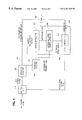
- FIG. 5 is a block diagram of a motion picture receiver designed to receive data transmitted by the transmitter shown in FIG. 4 and reproduce the motion picture represented by the transmitted information with an enhanced motion picture image.
- frames are interpolated between successive frames of a scene representing a motion picture containing one or more moving objects.
- FIG. 1 two successive frames, frame A and frame B, of a low frame rate motion picture are shown.
- the frames depict a stationary object in the form of a station house 200 and a moving object in the form of an engine 212 .
- the engine 212 has moved from a central position in frame A toward the lower right-hand corner of the scene as shown in frame B.
- the forward vectors 214 represent the motion of the image elements depicting the engine in the time interval between frames A and B.
- the frames A and B are compared to generate a dense forward vector field wherein a vector value is generated for each pixel in the image shown in frame A to indicate where the corresponding image element has been moved in the image in frame B.
- all of the image elements stay in the same position except the image elements representing the engine 212 .
- vectors 214 in the dense forward vector field are computed from the change in the position of the image elements depicting the engine 212 from frame A to frame B. Since the remaining image elements do not change position from frame A to frame B, the vectors for these stationary image elements will have a zero magnitude in the dense forward vector field.
- a dense backward vector field is generated representing the difference in the image element position from frame B to frame A.
- the dense backward vector field will contain backward vectors 234 corresponding to the image elements depicting the engine computed from the difference in the positions of the pixels depicting engine 212 in frame A from their position in frame B.
- vectors in the dense backward vector field which correspond to image elements which do not change in position from frame B to frame A, have zero magnitude.
- the term “dense vector field” as used herein means a set of vectors representing image element motion wherein the vectors have substantially the same density as the pixels or the image elements of the motion picture frames.
- the magnitudes of the vectors 214 and 234 are scaled to correspond to the location in time of the frame being interpolated between the frames A and B. Since the interpolated frame in the specific embodiment will be equally spaced in time from frame A and frame B, the magnitudes of the forward vectors and the backward vectors are reduced by one-half, resulting 1 ⁇ 2 scale forward vectors 224 and 1 ⁇ 2 scale backward vectors 226 .
- a first motion adjusted image is then generated from frame A and the 1 ⁇ 2 scale dense forward vector field. The first motion adjusted image will be derived from frame A by moving the image elements of frame A in accordance with the 1 ⁇ 2 scale forward vectors.
- All of the image elements of frame A which do not depict the engine 212 and for which the forward vectors have a magnitude of zero stay in the same position in the first motion adjusted image.
- the image elements depicting the engine 212 are moved in the first motion adjusted image to positions as indicated by the 1 ⁇ 2 scale forward vectors 224 , and, in the first motion adjusted image, the engine will appear halfway between its position in frame A and frame B.
- a second motion adjusted image is generated in a similar manner from frame B and the 1 ⁇ 2 scale backward vector field.
- the dense motion vector field may represent changes in object size, three-dimensional motion and other complex motion.
- the vectors of the dense motion vector field are scaled, they will sometimes call for placing more than one image element in the motion adjusted image in the same position.
- the image element depicting the lower lefthand comer of the engine 212 will be moved by its scaled forward vector to the position of a stationary image element so that in the motion adjusted image, two image elements will be assigned to the same position.
- This phenomena may be handled by a simple algorithm, such as by averaging the image elements, or by a simple rule or by means of additional image information.
- the end result may not be an ideal representation of the corresponding image element in the motion adjusted image, but the result does not critically affect the overall motion picture quality.
- first and second motion adjusted images are generated, they are merged to form an interpolated image.
- a simple algorithm for merging the two motion adjusted images would be to average the corresponding image elements in the two motion adjusted images.
- the algorithm for blending the image elements in the merged image determines whether the image element from the first frame or the second frame is a better representation of a given pixel in the interpolated frame.
- the preferred merging algorithm detects for each image element in the interpolated frame whether it is subject to occlusion or innovation phenomena. An occlusion phenomena is detected for an image element in the interpolated frame when the image element is visible in the first frame and is not visible in the second frame, thus indicating that the image element in the second frame has been occluded by a moving object.
- the image element from the first motion adjusted image is selected for the corresponding pixel in the interpolated image.
- An innovation phenomena is detected when an image element that was not visible in the first frame becomes visible in the second frame.
- the image element from the second motion adjusted image is selected for the corresponding pixel in an interpolated frame.
- Image elements which are not detected as being subject to occlusion or innovation phenomena from the image elements as represented in the first and second motion adjusted images are averaged in the interpolated frame.
- Successessive overlapping pairs of adjacent frames refers to the sequence wherein, if the successive frames are labeled A, B, C, D, then the frames B and C are a successive overlapping pair of adjacent frames to the pair of adjacent frames A and B and the frames C and D are a successive overlapping pair of adjacent frames to the pair of adjacent frames B and C.
- a standard compressed bit stream representing a low frame rate video motion picture in digital form is applied to a standard decoder 404 .
- the low frame rate motion picture may be a representation of the motion picture in which alternate frames have been discarded or may represent a motion picture originally produced at a low frame rate, such as by a low frame rate motion picture or video camera.
- the standard decoder 404 decompresses the received bit stream into successive video frames at the received low frame rate on channel 406 . Alternatively, the input bit stream need not be compressed.
- the video frames are applied to a motion extractor 412 of a motion enhancement module 410 , which also includes a motion adjusted interpolator 416 .
- the motion extractor 412 computes forward and backward dense motion vector fields for the image elements for each successive overlapping pair of adjacent frames as described above in connection with FIG. 1 .
- the details of motion extraction are disclosed in German application No. 95912250.8 and in published PCT application No. WO99/07156, which are hereby incorporated by reference.
- the forward and backward dense vector fields are applied to the motion adjusted interpolator 416 , which also receives the low frame rate video on channel 406 .
- the interpolator 416 generates interpolated frames from the received forward and backward dense vector fields and from the corresponding low frame rate video frames in the manner described above in connection with FIG. 1 .
- the interpolator 416 applies the interpolated frames to the interleavor 420 which interleaves the interpolated frames between the corresponding pairs of frames in the low frame rate video on channel 406 to produce a high frame rate video output on channel 430 .
- the high frame rate video on channel 430 is then displayed by a video display device 432 or, alternatively, is stored or recorded to be displayed later.
- FIG. 3 is a block diagram illustrating the motion adjusted interpolator and its operation. As shown in this diagram, an interpolated frame between Frames A and B is being created. Frame A is applied to the image element moving module 313 which also receives the dense forward vector field from the motion extractor 412 . In the image element moving module 313 , a first motion adjusted image is created by modifying frame A to move the image elements of frame A in accordance with the dense forward motion vector field received from the motion extractor 412 and scaled by 1 ⁇ 2. In a similar manner, image element moving module 323 receives frame B and the dense backward motion vector field from the motion extractor 412 .
- the image element moving module 323 creates a second motion adjusted image by moving the image elements of frame B in accordance with dense backward motion vector field scaled by 1 ⁇ 2.
- the first and second motion adjusted images are then merged in module 330 to produce the interpolated frame between frames A and B.
- the interpolator will create an interpolated frame between each successive overlapping pair of adjacent image frames.
- the system shown in FIG. 2 will operate on any motion picture, the frames of which are represented in digital form, and does not require a specifically constructed transmitter to transmit the motion picture frames.
- the system of FIG. 2 comprises a motion picture display appliance and the components thereof are accordingly colocated, or, in other words, at the same location in close proximity with one another.
- FIG. 4 is a block diagram illustrating a transmitter of the alternative embodiment of the invention
- FIG. 5 is a block diagram of a receiver of the alternative embodiment.
- the systems of FIGS. 4 and 5 in contrast with the system of FIGS. 2 and 3 requires a special transmitter.
- video data representing video frames of a motion picture at a high frame rate are received by a splitter 510 which sends alternate frames to a standard encoder 520 and sends the frames not sent to the encoder 520 to a comparator 570 in a motion enhancement module 540 .
- a splitter 510 which sends alternate frames to a standard encoder 520 and sends the frames not sent to the encoder 520 to a comparator 570 in a motion enhancement module 540 .
- odd frames are sent to the encoder 520 and that even frames are sent to the motion enhancement module 540 .
- the standard encoder 520 compresses the received odd frames and transmits the odd frames on output channel 522 .
- the compressed video data on channel 522 representing the odd frames is applied to a standard decoder 530 which decodes the frames back to their uncompressed state as produced at the output from the splitter 510 and applies the decompressed odd video frames to a motion extractor 550 in the motion enhancement module 540 .
- the standard decoder also applies the odd video frames to a motion adjusted interpolator 560 .
- the motion extractor 550 produces dense forward and backward vector fields in the manner described in connection with FIGS. 1-3 and applies the vector fields to the motion adjusted interpolator 560 .
- the motion adjustment interpolator 560 creates interpolated frames between the decoded odd frames produced by the standard decoder 530 in the manner described above in connection with FIGS.
- the motion adjusted interpolator 560 produced perfect interpolated frames, they would be identical to the actual even frames separated out by the splitter 510 . In fact, the interpolated frames will not be perfect and, as explained above, may contain artifacts when the video content is not well suited to extract high quality motion information by interpolation.
- the even frames received from the splitter are applied to a comparator 570 which receives the estimated interpolated even frames produced by the motion adjusted interpolator 560 .
- the difference between the interpolated or estimated even frames and the actual even frames applied to the comparator from the splitter are detected and the differences are transmitted as corrective data on output channel 542 .
- the corrective data is multiplexed with the odd frames on channel 522 in multiplexer 564 and transmitted to a receiver, which is illustrated in FIG. 5 .
- a demultiplexer 602 separates the corrective data from the standard bit stream of compressed data representing the odd frames.
- the standard bit stream is applied to a standard decoder 604 which decompresses the received data and produces a sequence of video frames corresponding to the odd frames produced by the splitter 510 in the transmitter.
- the odd frames produced by the standard decoder 604 are applied to a motion enhancement module 610 in which the odd frames are applied to a motion extractor and motion adjusted interpolator 616 which produces interpolated frames estimating the even frames of the original data applied to the splitter 510 in the transmitter.
- the estimated even frames or interpolated frames are produced in the same manner as described above in connection with FIGS. 1-3.
- a correction module 624 which receives the corrective data transmitted from the demultiplexer 602 .
- the corrective module 624 corrects the estimated even frames in accordance with the corrective data and applies corrected even frames to an interleavor 620 .
- the interleavor 620 then interleaves the corrected even frames with the odd frames produced by the standard decoder 604 to reproduce the sequence of video frames closely approximating those applied to the splitter 510 in the transmitter.
- a single interpolated image is determined for each pair of adjacent frames and, in this specific case, the forward and reverse vectors are scaled by a factor of 1 ⁇ 2 to correspond to the position in time of the interpolated image between the adjacent frames.
- the concept of the invention is applicable to producing more than one interpolated image between each pair of adjacent frames in which case, the forward and reverse vectors would be scaled accordingly. For example, if two interpolated images are generated between each pair of adjacent frames, the forward and reverse vectors would be scaled at one-third and two-thirds to produce two motion adjusted images from the forward vectors and two motion adjusted images from the backward vectors.
- the first interpolated image in the interval between the adjacent frames would then be produced from a merger of the motion adjusted image produced from the one-third scale forward vectors with the motion adjusted image produced from the two-thirds scale backward vectors.
- the second interpolated image in the interval between two adjacent frames would be generated by merging the motion adjusted image produced from the two-thirds scale forward vectors with the motion the adjusted image produced from the one-third scale backward vectors.
- the number of interpolated frames have to be an integer multiple of the number of original motion picture frames. When the interpolated frames are not integer multiple of the number of the original motion picture frames, some or most of the original motion picture frames may be discarded to maintain an even spacing of motion picture frames in the output sequence.
- one purpose of the invention is to improve the quality of the display of motion pictures represented by frames at a low frame rate.
- the invention is also useful for purposes of slow motion in high frame rate motion pictures.
- the input bit stream could represent a motion picture at a frame rate of 30 frames per second and the system shown in FIG. 2 could be used to generate interpolated frames between the high frame rate frames inputted to the system thus increasing the frame rate, such as by a multiple of two or more.
- the motion picture display device 430 would then be a slow motion display device which would display the received frames at a frame rate lower than the frame rate that the motion picture frames are received from the interleavor 420 , such as at the original frame rate represented by the input bit stream.
- the slow motion display device 430 would have a storage capacity to store the motion picture frames received at the high rate and reproduce the motion picture frames visually at the lower frame rate.
- the output frames from the interleavor 420 could be stored in a buffer storage device and applied to the motion picture display device 430 at the desired frame rate.
- the buffering of the motion picture frames could be carried out on the motion picture frames inputted to the system whereby the output of the interpolator when displayed would be in slow motion.
Abstract
Description
Claims (4)
Priority Applications (2)
| Application Number | Priority Date | Filing Date | Title |
|---|---|---|---|
| US09/459,988 US6351545B1 (en) | 1999-12-14 | 1999-12-14 | Motion picture enhancing system |
| PCT/US2000/042769 WO2001046756A1 (en) | 1999-12-14 | 2000-12-13 | Motion picture enhancing system |
Applications Claiming Priority (1)
| Application Number | Priority Date | Filing Date | Title |
|---|---|---|---|
| US09/459,988 US6351545B1 (en) | 1999-12-14 | 1999-12-14 | Motion picture enhancing system |
Publications (1)
| Publication Number | Publication Date |
|---|---|
| US6351545B1 true US6351545B1 (en) | 2002-02-26 |
Family
ID=23826958
Family Applications (1)
| Application Number | Title | Priority Date | Filing Date |
|---|---|---|---|
| US09/459,988 Expired - Fee Related US6351545B1 (en) | 1999-12-14 | 1999-12-14 | Motion picture enhancing system |
Country Status (2)
| Country | Link |
|---|---|
| US (1) | US6351545B1 (en) |
| WO (1) | WO2001046756A1 (en) |
Cited By (17)
| Publication number | Priority date | Publication date | Assignee | Title |
|---|---|---|---|---|
| US20020149696A1 (en) * | 2001-02-23 | 2002-10-17 | Eastman Kodak Company | Method for presenting improved motion image sequences |
| US20020168008A1 (en) * | 2001-05-08 | 2002-11-14 | Hiroyuki Ishikawa | Method and apparatus for coding moving pictures |
| US20030016750A1 (en) * | 2001-02-23 | 2003-01-23 | Eastman Kodak Company | Frame-interpolated variable-rate motion imaging system |
| US20030091112A1 (en) * | 2001-11-15 | 2003-05-15 | Li-Yi Chen | Display method for stabilizing MPEG video output via an LCD device |
| US6690386B2 (en) * | 2001-05-31 | 2004-02-10 | Dynapel Systems, Inc. | Medical image display system |
| US20040130680A1 (en) * | 2002-03-13 | 2004-07-08 | Samuel Zhou | Systems and methods for digitally re-mastering or otherwise modifying motion pictures or other image sequences data |
| US20040141658A1 (en) * | 2003-01-22 | 2004-07-22 | Haas William R. | Method and device for sorting similar images |
| US6934423B1 (en) * | 2000-03-20 | 2005-08-23 | Intel Corporation | Incorporating camera effects into existing video sequences |
| US20070153903A1 (en) * | 2002-03-15 | 2007-07-05 | Goh Itoh | Motion vector detection method and apparatus |
| US20080107186A1 (en) * | 2006-11-02 | 2008-05-08 | Mikhail Brusnitsyn | Method And Apparatus For Estimating And Compensating For Jitter In Digital Video |
| US20090027549A1 (en) * | 2004-05-17 | 2009-01-29 | Weisgerber Robert C | Method for processing motion pictures at high frame rates with improved temporal and spatial resolution, resulting in improved audience perception of dimensionality in 2-D and 3-D presentation |
| US20090116732A1 (en) * | 2006-06-23 | 2009-05-07 | Samuel Zhou | Methods and systems for converting 2d motion pictures for stereoscopic 3d exhibition |
| US20100231593A1 (en) * | 2006-01-27 | 2010-09-16 | Samuel Zhou | Methods and systems for digitally re-mastering of 2d and 3d motion pictures for exhibition with enhanced visual quality |
| US20110025911A1 (en) * | 2004-05-17 | 2011-02-03 | Weisgerber Robert C | Method of enhancing motion pictures for exhibition at a higher frame rate than that in which they were originally produced |
| US20120223939A1 (en) * | 2011-03-02 | 2012-09-06 | Noh Junyong | Rendering strategy for monoscopic, stereoscopic and multi-view computer generated imagery, system using the same and recording medium for the same |
| US10742883B2 (en) * | 2017-09-25 | 2020-08-11 | Casio Computer Co., Ltd. | Data processing method for generating composite image data indicating positional changes of an object |
| US11341725B2 (en) * | 2018-09-27 | 2022-05-24 | Apple Inc. | Intermediary emergent content |
Families Citing this family (2)
| Publication number | Priority date | Publication date | Assignee | Title |
|---|---|---|---|---|
| WO2005062623A1 (en) * | 2003-12-18 | 2005-07-07 | Nec Corporation | Moving image reproducing method, apparatus and program |
| US7783079B2 (en) * | 2006-04-07 | 2010-08-24 | Monro Donald M | Motion assisted data enhancement |
Citations (17)
| Publication number | Priority date | Publication date | Assignee | Title |
|---|---|---|---|---|
| US4575756A (en) | 1983-07-26 | 1986-03-11 | Nec Corporation | Decoder for a frame or field skipped TV signal with a representative movement vector used for individual vectors |
| US4651207A (en) * | 1984-03-05 | 1987-03-17 | Ant Nachrichtentechnik Gmbh | Motion adaptive interpolation of television image sequences |
| US4727422A (en) | 1985-06-03 | 1988-02-23 | Picturetel Corporation | Method and apparatus for efficiently communicating image sequence having improved motion compensation |
| US4838685A (en) * | 1987-04-03 | 1989-06-13 | Massachusetts Institute Of Technology | Methods and apparatus for motion estimation in motion picture processing |
| US4985768A (en) | 1989-01-20 | 1991-01-15 | Victor Company Of Japan, Ltd. | Inter-frame predictive encoding system with encoded and transmitted prediction error |
| US5121377A (en) | 1988-04-19 | 1992-06-09 | Bose Corporation | Error detection method and apparatus for reducing the number of errors generated when reading digital data stored on a recording medium such as film |
| US5121202A (en) | 1989-05-12 | 1992-06-09 | Nec Corporation | Adaptive interframe prediction coded video communications system |
| US5386234A (en) | 1991-11-13 | 1995-01-31 | Sony Corporation | Interframe motion predicting method and picture signal coding/decoding apparatus |
| USRE35093E (en) | 1990-12-03 | 1995-11-21 | The Trustees Of Columbia University In The City Of New York | Systems and methods for coding even fields of interlaced video sequences |
| USRE35158E (en) | 1989-04-27 | 1996-02-20 | Victor Company Of Japan Limited | Apparatus for adaptive inter-frame predictive encoding of video signal |
| US5742344A (en) | 1991-05-31 | 1998-04-21 | Kabushiki Kaisha Toshiba | Motion compensated video decoding method and system for decoding a coded video signal using spatial and temporal filtering |
| USRE35910E (en) | 1989-05-11 | 1998-09-29 | Matsushita Electric Industrial Co., Ltd. | Moving image signal encoding apparatus and decoding apparatus |
| US5825421A (en) * | 1995-12-27 | 1998-10-20 | Matsushita Electronic Industrial Co., Ltd. | Video coding method and decoding method and devices thereof |
| US5859668A (en) | 1993-12-13 | 1999-01-12 | Sharp Kabushiki Kaisha | Prediction mode selecting device in moving image coder |
| US5982440A (en) | 1996-09-17 | 1999-11-09 | Nec Corporation | Method and apparatus for producing slow-motion picture signal changing smoothly from compression coded picture signal |
| US6133789A (en) * | 1997-12-10 | 2000-10-17 | Nortel Networks Corporation | Method and system for robustly linearizing a radio frequency power amplifier using vector feedback |
| US6154491A (en) * | 1997-08-27 | 2000-11-28 | Kabushiki Kaisha Toshiba | Motion vector detecting method and apparatus |
-
1999
- 1999-12-14 US US09/459,988 patent/US6351545B1/en not_active Expired - Fee Related
-
2000
- 2000-12-13 WO PCT/US2000/042769 patent/WO2001046756A1/en active Application Filing
Patent Citations (17)
| Publication number | Priority date | Publication date | Assignee | Title |
|---|---|---|---|---|
| US4575756A (en) | 1983-07-26 | 1986-03-11 | Nec Corporation | Decoder for a frame or field skipped TV signal with a representative movement vector used for individual vectors |
| US4651207A (en) * | 1984-03-05 | 1987-03-17 | Ant Nachrichtentechnik Gmbh | Motion adaptive interpolation of television image sequences |
| US4727422A (en) | 1985-06-03 | 1988-02-23 | Picturetel Corporation | Method and apparatus for efficiently communicating image sequence having improved motion compensation |
| US4838685A (en) * | 1987-04-03 | 1989-06-13 | Massachusetts Institute Of Technology | Methods and apparatus for motion estimation in motion picture processing |
| US5121377A (en) | 1988-04-19 | 1992-06-09 | Bose Corporation | Error detection method and apparatus for reducing the number of errors generated when reading digital data stored on a recording medium such as film |
| US4985768A (en) | 1989-01-20 | 1991-01-15 | Victor Company Of Japan, Ltd. | Inter-frame predictive encoding system with encoded and transmitted prediction error |
| USRE35158E (en) | 1989-04-27 | 1996-02-20 | Victor Company Of Japan Limited | Apparatus for adaptive inter-frame predictive encoding of video signal |
| USRE35910E (en) | 1989-05-11 | 1998-09-29 | Matsushita Electric Industrial Co., Ltd. | Moving image signal encoding apparatus and decoding apparatus |
| US5121202A (en) | 1989-05-12 | 1992-06-09 | Nec Corporation | Adaptive interframe prediction coded video communications system |
| USRE35093E (en) | 1990-12-03 | 1995-11-21 | The Trustees Of Columbia University In The City Of New York | Systems and methods for coding even fields of interlaced video sequences |
| US5742344A (en) | 1991-05-31 | 1998-04-21 | Kabushiki Kaisha Toshiba | Motion compensated video decoding method and system for decoding a coded video signal using spatial and temporal filtering |
| US5386234A (en) | 1991-11-13 | 1995-01-31 | Sony Corporation | Interframe motion predicting method and picture signal coding/decoding apparatus |
| US5859668A (en) | 1993-12-13 | 1999-01-12 | Sharp Kabushiki Kaisha | Prediction mode selecting device in moving image coder |
| US5825421A (en) * | 1995-12-27 | 1998-10-20 | Matsushita Electronic Industrial Co., Ltd. | Video coding method and decoding method and devices thereof |
| US5982440A (en) | 1996-09-17 | 1999-11-09 | Nec Corporation | Method and apparatus for producing slow-motion picture signal changing smoothly from compression coded picture signal |
| US6154491A (en) * | 1997-08-27 | 2000-11-28 | Kabushiki Kaisha Toshiba | Motion vector detecting method and apparatus |
| US6133789A (en) * | 1997-12-10 | 2000-10-17 | Nortel Networks Corporation | Method and system for robustly linearizing a radio frequency power amplifier using vector feedback |
Cited By (29)
| Publication number | Priority date | Publication date | Assignee | Title |
|---|---|---|---|---|
| US6934423B1 (en) * | 2000-03-20 | 2005-08-23 | Intel Corporation | Incorporating camera effects into existing video sequences |
| US7242850B2 (en) * | 2001-02-23 | 2007-07-10 | Eastman Kodak Company | Frame-interpolated variable-rate motion imaging system |
| US20030016750A1 (en) * | 2001-02-23 | 2003-01-23 | Eastman Kodak Company | Frame-interpolated variable-rate motion imaging system |
| US20020149696A1 (en) * | 2001-02-23 | 2002-10-17 | Eastman Kodak Company | Method for presenting improved motion image sequences |
| US20020168008A1 (en) * | 2001-05-08 | 2002-11-14 | Hiroyuki Ishikawa | Method and apparatus for coding moving pictures |
| US6975681B2 (en) * | 2001-05-08 | 2005-12-13 | Nec Corporation | Method and apparatus for coding moving pictures |
| US6690386B2 (en) * | 2001-05-31 | 2004-02-10 | Dynapel Systems, Inc. | Medical image display system |
| US20030091112A1 (en) * | 2001-11-15 | 2003-05-15 | Li-Yi Chen | Display method for stabilizing MPEG video output via an LCD device |
| US20040130680A1 (en) * | 2002-03-13 | 2004-07-08 | Samuel Zhou | Systems and methods for digitally re-mastering or otherwise modifying motion pictures or other image sequences data |
| US7856055B2 (en) | 2002-03-13 | 2010-12-21 | Imax Corporation | Systems and methods for digitally re-mastering or otherwise modifying motion pictures or other image sequences data |
| US8144777B2 (en) * | 2002-03-15 | 2012-03-27 | Kabushiki Kaisha Toshiba | Motion vector detection method and apparatus |
| US20070153903A1 (en) * | 2002-03-15 | 2007-07-05 | Goh Itoh | Motion vector detection method and apparatus |
| US20070165719A1 (en) * | 2002-03-15 | 2007-07-19 | Goh Itoh | Motion vector detection method and apparatus |
| US20070153904A1 (en) * | 2002-03-15 | 2007-07-05 | Goh Itoh | Motion vector detection method and apparatus |
| US20040141658A1 (en) * | 2003-01-22 | 2004-07-22 | Haas William R. | Method and device for sorting similar images |
| US7450785B2 (en) * | 2003-01-22 | 2008-11-11 | Hewlett-Packard Development Company, L.P. | Method and device for sorting similar images |
| US20110025911A1 (en) * | 2004-05-17 | 2011-02-03 | Weisgerber Robert C | Method of enhancing motion pictures for exhibition at a higher frame rate than that in which they were originally produced |
| US20090027549A1 (en) * | 2004-05-17 | 2009-01-29 | Weisgerber Robert C | Method for processing motion pictures at high frame rates with improved temporal and spatial resolution, resulting in improved audience perception of dimensionality in 2-D and 3-D presentation |
| US20100231593A1 (en) * | 2006-01-27 | 2010-09-16 | Samuel Zhou | Methods and systems for digitally re-mastering of 2d and 3d motion pictures for exhibition with enhanced visual quality |
| US8842730B2 (en) | 2006-01-27 | 2014-09-23 | Imax Corporation | Methods and systems for digitally re-mastering of 2D and 3D motion pictures for exhibition with enhanced visual quality |
| US20090116732A1 (en) * | 2006-06-23 | 2009-05-07 | Samuel Zhou | Methods and systems for converting 2d motion pictures for stereoscopic 3d exhibition |
| US8411931B2 (en) | 2006-06-23 | 2013-04-02 | Imax Corporation | Methods and systems for converting 2D motion pictures for stereoscopic 3D exhibition |
| US9282313B2 (en) | 2006-06-23 | 2016-03-08 | Imax Corporation | Methods and systems for converting 2D motion pictures for stereoscopic 3D exhibition |
| US8130845B2 (en) | 2006-11-02 | 2012-03-06 | Seiko Epson Corporation | Method and apparatus for estimating and compensating for jitter in digital video |
| US20080107186A1 (en) * | 2006-11-02 | 2008-05-08 | Mikhail Brusnitsyn | Method And Apparatus For Estimating And Compensating For Jitter In Digital Video |
| US20120223939A1 (en) * | 2011-03-02 | 2012-09-06 | Noh Junyong | Rendering strategy for monoscopic, stereoscopic and multi-view computer generated imagery, system using the same and recording medium for the same |
| US10742883B2 (en) * | 2017-09-25 | 2020-08-11 | Casio Computer Co., Ltd. | Data processing method for generating composite image data indicating positional changes of an object |
| US11341725B2 (en) * | 2018-09-27 | 2022-05-24 | Apple Inc. | Intermediary emergent content |
| US11847744B2 (en) | 2018-09-27 | 2023-12-19 | Apple Inc. | Intermediary emergent content |
Also Published As
| Publication number | Publication date |
|---|---|
| WO2001046756A1 (en) | 2001-06-28 |
Similar Documents
| Publication | Publication Date | Title |
|---|---|---|
| US6351545B1 (en) | Motion picture enhancing system | |
| EP1057341B1 (en) | Motion vector extrapolation for transcoding video sequences | |
| KR102588146B1 (en) | Multi-view signal codec | |
| US8472524B2 (en) | Motion compensated frame rate conversion with protection against compensation artifacts | |
| US6415055B1 (en) | Moving image encoding method and apparatus, and moving image decoding method and apparatus | |
| EP0564597A1 (en) | Systems and methods for coding even fields of interlaced video sequences | |
| EP0648398A1 (en) | Motion compensated video processing | |
| US9241095B2 (en) | Method and system for adaptive temporal interpolation filtering for motion compensation | |
| JP2006270823A (en) | Method and device for image rate conversion | |
| US20020149696A1 (en) | Method for presenting improved motion image sequences | |
| US6930728B2 (en) | Scan conversion apparatus | |
| US4989089A (en) | Television picture coding device and corresponding decoding device, a television picture transmission system incorporating such devices, and transmission and receiving stages of such a system | |
| EP1596595A1 (en) | Apparatus and method for image rendering | |
| US20050078212A1 (en) | Method and apparatus for converting frame rate using time shifting and motion compensation | |
| JPH03167985A (en) | High efficiency coding device | |
| US6909752B2 (en) | Circuit and method for generating filler pixels from the original pixels in a video stream | |
| US20040066466A1 (en) | Progressive conversion of interlaced video based on coded bitstream analysis | |
| US6760376B1 (en) | Motion compensated upconversion for video scan rate conversion | |
| WO2001045036A1 (en) | Slow motion system | |
| JP5742048B2 (en) | Color moving image structure conversion method and color moving image structure conversion device | |
| JPH0646459A (en) | Multichannel encoding method | |
| KR100390813B1 (en) | Apparatus of video decoder for digital television having half-sized hard ware memory and method of the same | |
| JP6099104B2 (en) | Color moving image structure conversion method and color moving image structure conversion device | |
| JPH07203487A (en) | Stereo image processing unit | |
| JP2000069483A (en) | Scanning conversion system |
Legal Events
| Date | Code | Title | Description |
|---|---|---|---|
| AS | Assignment |
Owner name: INTERNATIONAL DIGITAL TECHNOLOGIES, INC., NEW YORK Free format text: ASSIGNMENT OF ASSIGNORS INTEREST;ASSIGNORS:EDELSON, STEVEN D.;DIEPOLD, KLAUS;REEL/FRAME:011304/0129 Effective date: 19991129 Owner name: INTERNATIONAL DIGITAL TECHNOLOGIES, INC., NEW YORK Free format text: ASSIGNMENT OF ASSIGNORS INTEREST;ASSIGNORS:EDELSON, STEVEN D.;DIEPOLD, KLAUS;REEL/FRAME:011304/0143 Effective date: 19991129 |
|
| AS | Assignment |
Owner name: DYNAPEL SYSTEMS, INC., NEW YORK Free format text: CERTIFICATE OF AMENDMENT OF THE CERTIFICATE OF INCORPORATION;ASSIGNOR:INTERNATIONAL DIGITAL TECHNOLOGIES INC.;REEL/FRAME:012315/0957 Effective date: 20000414 |
|
| FPAY | Fee payment |
Year of fee payment: 4 |
|
| AS | Assignment |
Owner name: NIO SECURITY SYSTEMS, INC., FLORIDA Free format text: CHANGE OF NAME;ASSIGNOR:DYNAPEL SYSTEMS, INC.;REEL/FRAME:021398/0446 Effective date: 20080711 |
|
| REMI | Maintenance fee reminder mailed | ||
| FEPP | Fee payment procedure |
Free format text: PAYOR NUMBER ASSIGNED (ORIGINAL EVENT CODE: ASPN); ENTITY STATUS OF PATENT OWNER: SMALL ENTITY |
|
| FPAY | Fee payment |
Year of fee payment: 8 |
|
| SULP | Surcharge for late payment |
Year of fee payment: 7 |
|
| AS | Assignment |
Owner name: NIO SECURITY, INC., FLORIDA Free format text: CORRECTIVE ASSIGNMENT TO CORRECT THE NAME OF ASSIGNEE, EXECUTION DATE, AND INTERNAL ADDRESS PREVIOUSLY RECORDED ON REEL 021398 FRAME 0446. ASSIGNOR(S) HEREBY CONFIRMS THE CHANGE OF NAME, EXECUTION DATE, AND INTERNAL ADDRESS;ASSIGNOR:DYNAPEL SYSTEMS, INC.;REEL/FRAME:031343/0483 Effective date: 20080509 |
|
| REMI | Maintenance fee reminder mailed | ||
| AS | Assignment |
Owner name: NIO INC., FLORIDA Free format text: CHANGE OF NAME;ASSIGNOR:NIO SECURITY, INC.;REEL/FRAME:031394/0031 Effective date: 20120201 |
|
| LAPS | Lapse for failure to pay maintenance fees | ||
| STCH | Information on status: patent discontinuation |
Free format text: PATENT EXPIRED DUE TO NONPAYMENT OF MAINTENANCE FEES UNDER 37 CFR 1.362 |
|
| FP | Lapsed due to failure to pay maintenance fee |
Effective date: 20140226 |