US6356262B1 - System and method for fast polyhedral cell sorting - Google Patents
System and method for fast polyhedral cell sorting Download PDFInfo
- Publication number
- US6356262B1 US6356262B1 US09/292,704 US29270499A US6356262B1 US 6356262 B1 US6356262 B1 US 6356262B1 US 29270499 A US29270499 A US 29270499A US 6356262 B1 US6356262 B1 US 6356262B1
- Authority
- US
- United States
- Prior art keywords
- cell
- cells
- bsp
- ordering
- visibility
- Prior art date
- Legal status (The legal status is an assumption and is not a legal conclusion. Google has not performed a legal analysis and makes no representation as to the accuracy of the status listed.)
- Expired - Lifetime
Links
Images


Classifications
-
- G—PHYSICS
- G06—COMPUTING; CALCULATING OR COUNTING
- G06T—IMAGE DATA PROCESSING OR GENERATION, IN GENERAL
- G06T15/00—3D [Three Dimensional] image rendering
- G06T15/10—Geometric effects
- G06T15/40—Hidden part removal
-
- G—PHYSICS
- G06—COMPUTING; CALCULATING OR COUNTING
- G06T—IMAGE DATA PROCESSING OR GENERATION, IN GENERAL
- G06T15/00—3D [Three Dimensional] image rendering
- G06T15/06—Ray-tracing
-
- G—PHYSICS
- G06—COMPUTING; CALCULATING OR COUNTING
- G06T—IMAGE DATA PROCESSING OR GENERATION, IN GENERAL
- G06T17/00—Three dimensional [3D] modelling, e.g. data description of 3D objects
- G06T17/005—Tree description, e.g. octree, quadtree
-
- G—PHYSICS
- G06—COMPUTING; CALCULATING OR COUNTING
- G06T—IMAGE DATA PROCESSING OR GENERATION, IN GENERAL
- G06T17/00—Three dimensional [3D] modelling, e.g. data description of 3D objects
- G06T17/20—Finite element generation, e.g. wire-frame surface description, tesselation
Definitions
- This invention relates to rendering three dimensional objects and/or volumes on a graphics computer. More specifically, the invention relates to ordering polyhedral cells of volumes in a visibility order for efficient visualization.
- a visibility ordering of a set of objects, from a given viewpoint, is a total order on the objects such that if object A obstructs object B, then B precedes A in the ordering. Such orderings are extremely useful in computer graphics. Since the late 1960s, several algorithms have been proposed for computing visibility ordering of objects. The classic article by Sutherland, Sproull and Schumacker (“A Characterization of Ten Hidden-Surface Algorithms”, ACM Computing Surveys, 1974), summarizes the early work in the area. At that point, the focus of the visibility ordering work was performing hidden-surface removal. With the advent of the z-buffer, computing visibility orderings was not so important anymore, since such computations were expensive, and the z-buffer provided a simple and effective (hardware) solution to the hidden-surface removal problem.
- volume rendering, and other graphics techniques were developed, which again required solutions to the visibility ordering problem.
- Max, Hanranhan, Crawfis (“Area and Volume Coherence for Efficient Visualization of 3D Scalar Functions”, pp 27-33, Computer Graphics (San Diego Workshop on Volume Visualization, 1990)
- a technique is proposed which can be used to compute visibility ordering of a special kind of mesh, namely a Delaunay triangulation.
- Class I algorithms have quadratic complexity, and have shown to be very slow in practice, and not suitable for use in any kind of interactive application.
- Class III algorithms are not suited for use in interactive applications, mainly because they usually lead to errors in the computed images, which in general might lead to undesirable results. Using Class III algorithms compromises not only the quality of the visualization, but ultimately it can lead to incorrect conclusions. For instance, a medical doctor can not rely on results obtained by using such techniques.
- An object of this invention is an improved method for computing visibility ordering of polyhedral cells.
- An object of this invention is an improved system and method for rendering three dimensional volumes.
- An object of this invention is an improved system and method for quickly and efficiently rendering three dimensional volumes represented by large data sets.
- An object of this invention is an improved system and method for quickly and efficiently rendering three dimensional volumes represented by unstructured (non convex) and large data sets where the volumes are sorted in a visibility order.
- our invention builds an ordering graph, composed of oriented edges between two cells.
- Each edge (A,B) corresponds to the fact that cell A has to be projected, or rendered, before B.
- Our invention comprises a set of ordering relations and rules that can be shown to generate, if one exists, a global ordering of the polyhedral cell complex.
- Our invention uses three different types of edges to accomplish this: Meshed Polyhedra Visibility Ordering (MPVO), Binary Space Partition (BSP) and Partially Projected Cell (PPC) edges, where MPVO edges are prior art described in “Visibility Ordering Meshed Polyhedra” by Peter Williams, and BSP and PPC edges are new for our invention.
- MPVO Meshed Polyhedra Visibility Ordering
- BSP Binary Space Partition
- PPC Partially Projected Cell
- MPVO edges exist between two cells that share a face.
- BSP edges In order to define the BSP edges, we must first compute a BSP-tree of the boundary faces of the cell complex. During this construction, some of the boundary faces of the cells will be ‘cut’ by the BSP-tree ‘extended’ faces, into multiple pieces. If we say C is the boundary cell, and c′, c′′, and so on, are the pieces of its boundary faces, we define BSP_edge (c′, C) to mean that cell C can only be projected after c′ has been projected by the BSP.
- PPC edges We say a cell C is in the PPC if one of the pieces that compose it, say c′, has been projected by the BSP, but there exist other pieces of cell C that have not been projected. In this case, our system needs to perform additional checks to ensure cells are not being projected out of order. This is accomplished by performing ‘ray shooting’ queries, which we call XMPVO queries.
- FIG. 1 is a block diagram of one embodiment of an graphics computer.
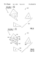
- FIG. 2 is a drawing of several polyhedral cells in a space with their visibility ordering numbers indicated.
- FIG. 3 is a drawing of several polyhedral cells in a space with their MPVO ordering indicated.
- FIG. 4 is a drawing of a graph which indicates the MPVO ordering dependencies among polyhedral cells.
- FIG. 5 is a drawing of several polyhedral cells in a space with their XMPVO (ray shooting) ordering indicated.
- FIG. 6 is a drawing of a graph which indicates the XMPVO ordering dependencies among polyhedral cells.
- FIG. 7 is a drawing of several polyhedral cells in a space with a binary space partitioning (BSP) tree used in preferred embodiment of the invention.
- BSP binary space partitioning
- FIG. 8 is a drawing of a graph which indicates the BSP ordering dependencies among polyhedral cells.
- FIG. 9 is a block diagram which indicates how a total ordering can be achieved by our invention.
- FIG. 10 is a flow chart of a rendering process.
- FIG. 11A is a flow chart of a visibility ordering process.
- FIG. 11B is a flow chart of a BSP traversal process.
- FIG. 11C is a flow chart of an update all dependencies process.
- FIG. 11D is a flow chart of an update PPC dependencies process.
- FIG. 11E is a flow chart of an update PPC dependency count process.
- FIG. 11F is a flow chart of an update PPC list process.
- FIG. 11G is a flow chart of an update BSP process.
- FIG. 11H is a flow chart of a MPVO traverse process.
- FIG. 1 is a block diagram of one embodiment of a graphics computer.
- a graphics computer is typically comprised of a well known Central Processing Unit (CPU) 102 , a memory subsystem 104 , and an Input Output (I/O) subsystem 106 . These subsystems communicate through a data bus 108 .
- the system might also include a graphics coprocessor 110 which can offload from the CPU many computation-intensive tasks.
- An optional graphics accelerator subsystem 112 can also be used by the system.
- the images produced by the graphics computer are visualized using the display 114 .
- the processes 1000 described in FIGS. 10 and 11 A- 11 H are typically stored in the memory 104 and executed by the CPU 102 .
- FIG. 2 is a drawing of six polyhedral cells 203 in space together with a viewpoint 201 and viewing direction 202 .
- a visibility ordering we have numbered each of the cells according to their visibility ordering.
- To render the cells in correct order we render the cells from largest number to smallest number.
- FIG. 3 is a drawing of the same six polyhedral cells in FIG. 2 together with the MPVO visibility ordering relations.
- a viewpoint 301 and a view direction 302 are specified.
- MPVO dependencies exist between cells that share a face.
- cell 5 ( 309 ) and cell 6 ( 308 ) do not have any MPVO dependencies since they do not share faces with any other cells.
- cell 1 ( 303 ), cell 2 ( 304 ), cell 3 ( 306 ), and cell 4 ( 305 ) do have some faces in common. Therefore, we have indicated the MPVO dependencies by arrows 307 in the figure.
- the direction of the arrow is of vital importance, as it indicates that which of the two neighboring cells needs to be projected, or rendered, first.
- the arrow 307 points from the cell that should be projected first towards the cell that should be projected second. For example, we know that cell 2 ( 304 ) should be projected before cell 1 ( 303 ) since we are projecting cells in a back-to-front order with respect to the current viewpoint 301 . Therefore, we have included an arrow 307 which points from cell 2 ( 304 ) to cell 1 ( 303 ).
- FIG. 4 is a drawing of a graph which indicates the MPVO ordering dependencies among polyhedral cells.
- the graph is used as a simple illustration of the MPVO dependencies.
- Each of the six original cells is represented by a numbered node of the graph 401 - 406 .
- the MPVO dependencies highlighted in FIG. 3 are again represented by arrows 407 - 410 , pointing from the cell that needs to be projected first, to the cell that needs to be projected second.
- FIG. 5 is a drawing of the same six polyhedral cells in FIG. 2 together with their XMPVO (ray shooting) ordering indicated.
- the XMPVO ordering adds only one dependency between cell 5 ( 507 ) and cell 4 ( 506 ), which can be seen by the arrow 509 from cell 5 507 to cell 4 ( 506 ).
- Additional ray shooting queries 510 are indicated for clarity, even though they do not add any dependencies. The ray shooting queries are made in the opposite direction of the view direction 502 .
- FIG. 6 is a drawing of a graph which indicates the XMPVO ordering dependencies among polyhedral cells.
- the graph is used as a simple illustration of the XMPVO dependencies.
- Each of the six original cells is represented by a numbered node of the graph 601 - 606 .
- the XMPVO dependency highlighted in FIG. 5 is again represented by an arrow 607 , pointing from the cell that needs to be projected first 605 , to the cell that needs to be projected second 604 .
- FIG. 7 is a drawing of six polyhedral cells in a space with a binary space partitioning (BSP) tree used in a preferred embodiment of the invention.
- the viewpoint 701 and view direction 702 are indicated with an arrow.
- the BSP-tree is built upon the boundary faces of the cells.
- the cutting planes associated with the BSP-tree are highlighted by the letters A through L and the numbers 703 through 714 , respectively.
- the BSP-tree was constructed in the order of the cutting planes. That is, plane A 703 was used first to cut the region of space into two smaller regions. Plane B 704 was used next to cut the right region, with respect to plane A 703 , into two smaller regions.
- cell 6 ( 720 ) has three boundary faces ( 704 , 705 , 706 ), none of which were cut by the BSP-tree construction phase.
- cell 5 ( 725 ), which originally had three boundary faces, ended up with five boundary segments ( 707 , 708 , 712 , 713 , 714 ) after the BSP-tree was constructed.
- FIG. 8 is a drawing of a graph which indicates the BSP ordering dependencies among the six polyhedral cells in FIG. 7 .
- Each cutting plane from FIG. 7 was referenced by a letter A through L, respectively.
- Each of these cutting planes is represented here by circles labeled A through L, respectively.
- the cutting planes have been placed within larger circles 801 - 805 to indicate the cell that has a boundary face which lies on the cutting plane.
- cell 4 ( 803 ) had only one boundary face in FIG. 7, therefore, the circle which represents cell 4 ( 803 ) in FIG. 8 contains only one smaller circle which represents the cutting plane along this boundary face.
- cell 6 ( 805 ) had three boundary faces in FIG. 7 and thus has three smaller circles in this FIG. 8 .
- the arrows 806 - 816 in the figure represent the BSP dependencies between the cells.
- FIG. 9 is a block diagram 900 which indicates how a total visibility ordering 901 can be achieved by our invention.
- the visibility ordering can be comprised of the MPVO dependencies 902 and the XMPVO dependencies 903 .
- all the visibility ordering relations among boundary cells are achieved by using ray-shooting queries.
- a more efficient means of achieving the ordering can be accomplished by using the MPVO dependencies 904 , the BSP dependencies 905 , and the PPC dependencies 906 .
- the introduction of the BSP dependencies enables us to eliminate a large number of ray-shooting queries, but not all of them. Cells that have a face cut by more than one BSP plane will be “partially projected” by the BSP.
- the partially projected cell dependencies are equivalent to the XMPVO dependencies 903 , although in general they are only a subset of them. Consequently, the BSP dependencies 905 and the PPC dependencies 906 are needed to replace the more expensive XMPVO dependencies.
- FIG. 10 is a flow chart of a rendering process 1000 , which sequentially renders the input polyhedral cells in visibility order for a series of viewpoints.
- the Render Cells process 1000 takes as input an initial viewpoint 1002 and a set of polyhedral cells 1004 .
- the plane equation for each face of each input cell is computed 1006 using well-known techniques.
- the plane equations will be used later to determine 1103 the MPVO dependencies among the cells.
- a binary space partition tree, or BSP-tree is computed 1008 using the boundary faces of the input cells.
- the technique used to build the BSP can be chosen among several well-known algorithms. A novel piece of our algorithm is that we use the BSP built upon the only the boundary faces to sort the internal cells.
- a Visibility Sort process 1010 is performed to sort in visibility order the input cells 1004 .
- Our traversal algorithm is highlighted in FIGS. 11A-H.
- the input cells 1004 can then be rendered, using standard techniques, 1012 in the correct order.
- the viewpoint is then updated 1014 so that we can again perform our Visibility Sort process 1010 and render the cells 1012 using the updated viewpoint.
- FIG. 11A is a flow chart of the Visibility Sort process 1010 .
- Input for the visibility sort are the current viewpoint 1101 and the BSP-tree 1102 which was previously built upon the boundary faces of the input cells in process 1008 . refer back to the piece in 1008 so it ties together?
- the first step in our visibility sort is to compute 1103 the MPVO dependencies between all cells which share a face. This prior art was described in “Visibility Ordering Meshed Polyhedra” by Peter Williams.
- the process 1010 calls our recursive function BSP Traversal 1104 , with the current viewpoint 1101 and the root node of the BSP-tree as input parameters. Once the recursive function has finished, the visibility sort is completed and we return 1105 .
- FIG. 11B is a flow chart of the BSP Traversal process 1104 .
- the input parameters are a node 1106 of the BSP-tree and the current viewpoint 1107 .
- we test 1108 if the node is equal to null. If it is, we return 1109 from the function. Otherwise, we test 1110 if the viewpoint 1107 is in front of the cutting plane associated with the node. This test is necessary as we want to visit the regions of space defined by the BSP-tree in back-to-front order, thereby helping us to find the visibility order of the cells.
- the viewpoint is in front of the cutting plane, then to project the cells in a back-to-front order, we will need to visit the BACK child node, process the current node, and then visit the FRONT child node. If the viewpoint is in back of the cutting plane, we need to do the reverse: visit the FRONT child node, process the current node, and then visit the BACK child node.
- FIG. 11C is a flow chart of the Update All Dependencies process 1112 , 1115 .
- the input parameters for this process are a node of the BSP-tree 1120 and the current viewpoint 1121 .
- An initial test is performed 1122 to determine if there are any partially projected cells, or PPCs. Recall that a partially projected cell C is a cell such that one of the pieces, created by the BSP construction, that compose it, say c′, has been projected by the BSP, but there exist other pieces of cell C that have not been projected. If there are PPCs, we call another process 1123 to Update PPC Dependencies, using the same input 1120 , 1121 as this process. The remaining steps in this process are straightforward. We call three processes: Update PPC List 1124 , Update BSP Dependencies 1125 , and MPVO Traverse 1126 . Finally, we return 1127 . See the description FIGS. 11F, 11 G, and 11 H, below.
- the Update PPC Dependencies process 1123 is described by a flow chart in FIG. 11 D.
- the input to this process are a node of the BSP-tree 1130 and the current viewpoint 1131 .
- This process is only called if we know there are partially projected cells, therefore, we begin by assigning 1132 to the current_PPC_cell variable the first partially projected cell.
- Associated with the current node 1130 is a cutting plane.
- Using the current_PPC_cell and the current_CCN_cell we call a process 1134 to Update PPC Dependency Count.
- FIG. 11E is a flow chart of the Update PPC Dependency Count process 1134 .
- the input to this process are a partially projected cell C_i 1140 , a cell C_j 1141 with a face which lies on the current cutting plane, and the current viewpoint 1142 .
- the spheres S_i 1143 and S_j 1144 around the two input cells C_i and C_j.
- the Update PPC List process 1124 takes one input parameter, a node of the BSP-tree 1150 . Associated with each node of the BSP-tree is a cutting plane.
- the Update PPC List process 1124 considers each cell that has a face which lies on the cutting plane associated with the current node 1150 , and determines whether we need to add or delete the cell to the partially projected cell list. Initially, we set 1151 the current_cell variable to be the first cell which has a face that lies on the current cutting plane. If the current_cell has already been visited 1152 , meaning that it has already been considered for the partially projected cell list, we determine 1153 if the number of BSP dependencies for the current_cell is equal to one.
- the current cutting plane represents this last BSP dependency and so we can remove 1154 the current_cell from the PPC list. If the number of BSP dependencies is greater than one, we will consider any additional cells that have faces which lies on the current cutting plane 1157 .
- the current_cell has not been considered for the PPC list yet, we determine 1155 it has more than one BSP dependency. If it does, then we insert 1156 the current_cell to the PPC list. Otherwise, we determine 1157 if there are any remaining cells that have faces which lie on the current cutting plane. If yes, we update 1158 the current_cell variable to be the next such cell, and repeat our tests 1152 to determine if we need to add or delete the cell from the PPC list. Once there are no additional cells to test, we return from this function 1159 .
- FIG. 11G details our Update BSP Dependencies process 1125 .
- the process will decrement the BSP dependency count for each cell that has a face which lies on the cutting plane associated with the current node 1162 .
- the BSP dependency count for the current cell is then decremented 1164 . If the current_cell has no remaining MPVO, BSP, or PPC dependencies 1165 , then we add 1166 the current_cell may be projected and we add it to the DEQUE data structure.
- FIG. 11H is a flow chart of our MPVO Traverse process 1126 , which is responsible for projecting the input cells in the order determined by the visibility sort.
Abstract
Description
Claims (8)
Priority Applications (1)
| Application Number | Priority Date | Filing Date | Title |
|---|---|---|---|
| US09/292,704 US6356262B1 (en) | 1998-04-16 | 1999-04-15 | System and method for fast polyhedral cell sorting |
Applications Claiming Priority (2)
| Application Number | Priority Date | Filing Date | Title |
|---|---|---|---|
| US8200998P | 1998-04-16 | 1998-04-16 | |
| US09/292,704 US6356262B1 (en) | 1998-04-16 | 1999-04-15 | System and method for fast polyhedral cell sorting |
Publications (1)
| Publication Number | Publication Date |
|---|---|
| US6356262B1 true US6356262B1 (en) | 2002-03-12 |
Family
ID=26766631
Family Applications (1)
| Application Number | Title | Priority Date | Filing Date |
|---|---|---|---|
| US09/292,704 Expired - Lifetime US6356262B1 (en) | 1998-04-16 | 1999-04-15 | System and method for fast polyhedral cell sorting |
Country Status (1)
| Country | Link |
|---|---|
| US (1) | US6356262B1 (en) |
Cited By (3)
| Publication number | Priority date | Publication date | Assignee | Title |
|---|---|---|---|---|
| US20050122323A1 (en) * | 2003-12-09 | 2005-06-09 | Electronic Data Systems Corporation | System and method for transparency rendering |
| US20050231508A1 (en) * | 2004-02-12 | 2005-10-20 | Pixar | Multiresolution geometry caching based on ray differentials with stitching |
| US7181377B1 (en) * | 2002-06-24 | 2007-02-20 | Sandia Corporation | Method of modifying a volume mesh using sheet extraction |
Citations (4)
| Publication number | Priority date | Publication date | Assignee | Title |
|---|---|---|---|---|
| US5459822A (en) | 1992-09-29 | 1995-10-17 | Ricoh Company, Ltd. | Sorting processor |
| US5555352A (en) | 1991-04-23 | 1996-09-10 | International Business Machines Corporation | Object-based irregular-grid volume rendering |
| US5742293A (en) * | 1992-06-19 | 1998-04-21 | International Business Machines Corporation | Data visualizer utilizing exterior selected and depth sorted polyhedron faces |
| US5914721A (en) * | 1991-06-28 | 1999-06-22 | Lim; Hong Lip | Visibility calculations for 3D computer graphics |
-
1999
- 1999-04-15 US US09/292,704 patent/US6356262B1/en not_active Expired - Lifetime
Patent Citations (5)
| Publication number | Priority date | Publication date | Assignee | Title |
|---|---|---|---|---|
| US5555352A (en) | 1991-04-23 | 1996-09-10 | International Business Machines Corporation | Object-based irregular-grid volume rendering |
| US5914721A (en) * | 1991-06-28 | 1999-06-22 | Lim; Hong Lip | Visibility calculations for 3D computer graphics |
| US6172679B1 (en) * | 1991-06-28 | 2001-01-09 | Hong Lip Lim | Visibility calculations for 3D computer graphics |
| US5742293A (en) * | 1992-06-19 | 1998-04-21 | International Business Machines Corporation | Data visualizer utilizing exterior selected and depth sorted polyhedron faces |
| US5459822A (en) | 1992-09-29 | 1995-10-17 | Ricoh Company, Ltd. | Sorting processor |
Non-Patent Citations (4)
| Title |
|---|
| ACM Symposium on Volume Visualization, 10/98, pp. 87-94. |
| C.Silva et al, An Exact Interactive Time Visibility Ordering Algorithm for Polyhedral Cell Complexes. |
| Eurographics '99/P. Brunet and R. Scopigno, vol. 18 (1999), No. 3. |
| J. Comba et al, Fast Polyhedral Cell Sorting for Interactive Rendering of Unstructured Grids. |
Cited By (6)
| Publication number | Priority date | Publication date | Assignee | Title |
|---|---|---|---|---|
| US7181377B1 (en) * | 2002-06-24 | 2007-02-20 | Sandia Corporation | Method of modifying a volume mesh using sheet extraction |
| US20050122323A1 (en) * | 2003-12-09 | 2005-06-09 | Electronic Data Systems Corporation | System and method for transparency rendering |
| WO2005057502A1 (en) * | 2003-12-09 | 2005-06-23 | Ugs Corp. | System and method for transparency rendering |
| US7583263B2 (en) | 2003-12-09 | 2009-09-01 | Siemens Product Lifecycle Management Software Inc. | System and method for transparency rendering |
| US20050231508A1 (en) * | 2004-02-12 | 2005-10-20 | Pixar | Multiresolution geometry caching based on ray differentials with stitching |
| US7196704B2 (en) * | 2004-02-12 | 2007-03-27 | Pixar | Multiresolution geometry caching based on ray differentials with stitching |
Similar Documents
| Publication | Publication Date | Title |
|---|---|---|
| US6597359B1 (en) | Hierarchical space subdivision hardware for ray tracing | |
| US20220245111A1 (en) | Hierarchy Merging in Computer Graphics | |
| US5914721A (en) | Visibility calculations for 3D computer graphics | |
| Blelloch et al. | Design and implementation of a practical parallel Delaunay algorithm | |
| Weiler et al. | Hidden surface removal using polygon area sorting | |
| US8471845B1 (en) | System and method for constructing a bounding volume hierarchical structure | |
| US8797324B2 (en) | Direct ray tracing of 3D scenes | |
| Agarwal et al. | Kinetic binary space partitions for intersecting segments and disjoint triangles | |
| EP3933779A1 (en) | Intersection testing in a ray tracing system | |
| JPH03176784A (en) | Polygon decomposition method and apparatus in computer graphics | |
| US6574360B1 (en) | Accelerated occlusion culling using directional discretized occluders and system therefore | |
| US7460119B2 (en) | Invisible space skipping with adaptive granularity for texture-based volume rendering | |
| JP3034483B2 (en) | Object search method and apparatus using the method | |
| US7961186B2 (en) | Brick-based fusion renderer | |
| Plate et al. | A flexible multi-volume shader framework for arbitrarily intersecting multi-resolution datasets | |
| Rivara | Lepp-bisection algorithms, applications and mathematical properties | |
| US6356262B1 (en) | System and method for fast polyhedral cell sorting | |
| Rossignac et al. | Correct shading of regularized CSG solids using a depth-interval buffer | |
| Franklin et al. | Adaptive grid for polyhedral visibility in object space: an implementation | |
| Spackman | Scene decompositions for accelerated ray tracing | |
| EP3933781A1 (en) | Intersection testing in a ray tracing system | |
| Krishnan et al. | Interactive boundary computation of boolean combinations of sculptured solids | |
| Zhou et al. | Selectively meshed surface representation | |
| US10529444B1 (en) | System that rapidly generates a solvent-excluded surface | |
| Noguera et al. | A Vectorized Traversal Algorithm for Ray Tracing. |
Legal Events
| Date | Code | Title | Description |
|---|---|---|---|
| AS | Assignment |
Owner name: INTERNATIONAL BUSINESS MACHINES CORPORATION, NEW Y Free format text: ASSIGNMENT OF ASSIGNORS INTEREST;ASSIGNORS:TAUBIN, GABRIEL;WILLIAMS, PETER LAWRENCE;MITCHELL, JOSEPH SHANNON BAIRD;AND OTHERS;REEL/FRAME:010478/0051;SIGNING DATES FROM 19991004 TO 19991216 Owner name: INTERNATIONAL BUSINESS MACHINES CORPORATION, NEW Y Free format text: ASSIGNMENT OF ASSIGNORS INTEREST;ASSIGNORS:KLOSOWSKI, JAMES THOMAS;SILVA, CLAUDIO T.;REEL/FRAME:010478/0055;SIGNING DATES FROM 19991001 TO 19991027 |
|
| STCF | Information on status: patent grant |
Free format text: PATENTED CASE |
|
| FEPP | Fee payment procedure |
Free format text: PAYOR NUMBER ASSIGNED (ORIGINAL EVENT CODE: ASPN); ENTITY STATUS OF PATENT OWNER: LARGE ENTITY |
|
| FPAY | Fee payment |
Year of fee payment: 4 |
|
| FPAY | Fee payment |
Year of fee payment: 8 |
|
| REMI | Maintenance fee reminder mailed | ||
| AS | Assignment |
Owner name: TWITTER, INC., CALIFORNIA Free format text: ASSIGNMENT OF ASSIGNORS INTEREST;ASSIGNOR:INTERNATIONAL BUSINESS MACHINES CORPORATION;REEL/FRAME:032075/0404 Effective date: 20131230 |
|
| FPAY | Fee payment |
Year of fee payment: 12 |
|
| SULP | Surcharge for late payment |
Year of fee payment: 11 |