US6356608B1 - Method, apparatus, and system for determining a location of a frequency synchronization signal - Google Patents
Method, apparatus, and system for determining a location of a frequency synchronization signal Download PDFInfo
- Publication number
- US6356608B1 US6356608B1 US09/106,227 US10622798A US6356608B1 US 6356608 B1 US6356608 B1 US 6356608B1 US 10622798 A US10622798 A US 10622798A US 6356608 B1 US6356608 B1 US 6356608B1
- Authority
- US
- United States
- Prior art keywords
- peak value
- quality factor
- frequency offset
- frequency
- phase differences
- Prior art date
- Legal status (The legal status is an assumption and is not a legal conclusion. Google has not performed a legal analysis and makes no representation as to the accuracy of the status listed.)
- Expired - Lifetime
Links
Images


Classifications
-
- H—ELECTRICITY
- H04—ELECTRIC COMMUNICATION TECHNIQUE
- H04B—TRANSMISSION
- H04B7/00—Radio transmission systems, i.e. using radiation field
- H04B7/24—Radio transmission systems, i.e. using radiation field for communication between two or more posts
- H04B7/26—Radio transmission systems, i.e. using radiation field for communication between two or more posts at least one of which is mobile
-
- H—ELECTRICITY
- H04—ELECTRIC COMMUNICATION TECHNIQUE
- H04W—WIRELESS COMMUNICATION NETWORKS
- H04W56/00—Synchronisation arrangements
- H04W56/0035—Synchronisation arrangements detecting errors in frequency or phase
-
- H—ELECTRICITY
- H04—ELECTRIC COMMUNICATION TECHNIQUE
- H04B—TRANSMISSION
- H04B7/00—Radio transmission systems, i.e. using radiation field
- H04B7/24—Radio transmission systems, i.e. using radiation field for communication between two or more posts
- H04B7/26—Radio transmission systems, i.e. using radiation field for communication between two or more posts at least one of which is mobile
- H04B7/2662—Arrangements for Wireless System Synchronisation
- H04B7/2671—Arrangements for Wireless Time-Division Multiple Access [TDMA] System Synchronisation
- H04B7/2675—Frequency synchronisation
-
- H—ELECTRICITY
- H04—ELECTRIC COMMUNICATION TECHNIQUE
- H04L—TRANSMISSION OF DIGITAL INFORMATION, e.g. TELEGRAPHIC COMMUNICATION
- H04L27/00—Modulated-carrier systems
- H04L27/18—Phase-modulated carrier systems, i.e. using phase-shift keying
- H04L27/22—Demodulator circuits; Receiver circuits
- H04L27/233—Demodulator circuits; Receiver circuits using non-coherent demodulation
- H04L27/2332—Demodulator circuits; Receiver circuits using non-coherent demodulation using a non-coherent carrier
-
- H—ELECTRICITY
- H04—ELECTRIC COMMUNICATION TECHNIQUE
- H04L—TRANSMISSION OF DIGITAL INFORMATION, e.g. TELEGRAPHIC COMMUNICATION
- H04L7/00—Arrangements for synchronising receiver with transmitter
- H04L7/04—Speed or phase control by synchronisation signals
- H04L7/041—Speed or phase control by synchronisation signals using special codes as synchronising signal
- H04L7/042—Detectors therefor, e.g. correlators, state machines
-
- H—ELECTRICITY
- H04—ELECTRIC COMMUNICATION TECHNIQUE
- H04L—TRANSMISSION OF DIGITAL INFORMATION, e.g. TELEGRAPHIC COMMUNICATION
- H04L27/00—Modulated-carrier systems
- H04L27/0014—Carrier regulation
- H04L2027/0044—Control loops for carrier regulation
- H04L2027/0063—Elements of loops
- H04L2027/0065—Frequency error detectors
Definitions
- This invention relates generally to a method, apparatus, and system for determining a location of a frequency synchronization signal. More particularly, this invention relates to a method, apparatus, and system for determining a location of a frequency synchronization signal among data transmitted from a transmitter and received by a receiver in a communication system.
- a receiver In any communication system, it is important for a receiver to be synchronized with a transmitter so that messages can be successfully exchanged between the transmitter and the receiver. In a radio communication system, in particular, it is important that a receiver be tuned to the frequency of the transmitter for optimal reception.
- remote stations communicate with one or more base stations via a radio air interface.
- Various approaches have been employed to prevent transmissions between the various base stations and remote stations from interfering with each other.
- neighboring base stations are each assigned a different carrier frequency with which to communicate with remote stations so that transmissions from one base station do not interfere with transmissions from a neighboring base station.
- FDMA Frequency Division Multiple Access
- TDMA Time Division Multiple Access
- a base station may allocate a particular time slot or slots within a frame on a carrier to each remote station. Some remote stations can use the same carrier frequency but different time slots to communicate with the base station.
- CDMA Code Division Multiple Access
- each remote station is assigned a particular digital code word(s) that is orthogonal to code words assigned to other stations.
- Neighboring base stations can exchange messages with remote stations using the same frequency but different digital orthogonal code words to indicate which remote station the messages are designated for.
- a radio communication system employs FDMA, TDMA, CDMA, a combination of these approaches, or some other approach, it is important for a remote station to be time and frequency synchronized to the base station serving the area from which it desires to communicate.
- the frequency reference of the remote station must be tuned to the carrier frequency of the base station, and the time reference of the remote station must be synchronized to the time reference of the base station.
- a periodic synchronization signal is typically transmitted from the base station to the remote station for this purpose.
- GSM European Global System for Mobile Communication
- information is transmitted from the base station to a remote station by modulating the carrier of the base station with, e.g., a Normal Burst (NB) of data.
- NB Normal Burst
- the carrier of the base station is also modulated from time to time with a Frequency Correction Burst (FCB) and a Synchronization Burst (SB) to form a frequency synchronization signal.
- FCB Frequency Correction Burst
- SB Synchronization Burst
- the carrier of the base station is typically modulated with the FCB using Gaussian Minimum Shift Keying (GMSK).
- GMSK Gaussian Minimum Shift Keying
- a FCB is a sequence of 148 symbols, each symbol a zero, that transforms into a pure sinusoidal signal after modulation.
- the frequency of the resulting frequency synchronization signal is thus equal to 1/4T Hz, where T represents a symbol duration.
- T is typically 48/13 microseconds ( ⁇ s), so that the frequency synchronization signal has a frequency of approximately 67.7 KHz.
- the FCB is repeated every tenth frame for the first four times, and then for the fifth time, the FCB is repeated on the eleventh frame. This frame sequence is then repeated indefinitely, to maintain synchronization between the remote station and the base station.
- the remote station From the information in the FCB, the remote station is able to roughly synchronize itself with the time slot(s) allocated to it. This rough time synchronization is then sufficient to locate the SB, which is typically located eight bursts after the FCB, and to decode the information it carries. The information obtained by decoding the SB is then used to finely tune the frequency reference of the remote station to the carrier frequency of the base station and to adjust the remote station's time reference to the time slot(s) allocated to it by the base station.
- each base station transmits a frequency synchronization signal in the form of, for example, a pilot sequence on each of the frequencies assigned to that particular base station as well as possibly on some or all of the frequencies that are not assigned to that particular base station. If the frequency has been assigned to the base station, the corresponding pilot sequence may be transmitted with slightly more power than the other frequencies used by the base station.
- Each remote station receiving the carrier modulated by the pilot sequence demodulates the signal. As a result, each remote station can receive signals designated for it and simultaneously measure the signal strengths of neighboring base stations using different pilots or carriers. This information is used by the remote station to determine which received pilot sequence has the strongest signal strength, and the frequency reference of the remote station is adjusted to the appropriate carrier frequency, accordingly.
- any frequency difference between the frequency reference of the remote station and the carrier frequency of the base station is readily detected in the demodulated frequency synchronization signal.
- the difference between the frequency of the modulated frequency synchronization signal, which is known to be 67.7 KHz, and the frequency of the received frequency synchronization signal, demodulated to the baseband is a direct measure of the error in the frequency reference of the remote station.
- the difference between the known frequency of the strongest transmitted pilot sequence and the frequency of the demodulated pilot sequence is used by the remote station as a measure of the error in the frequency reference of the remote station.
- the remote station To accurately estimate the frequency offset and thus tune the remote station to the carrier frequency of the base station, it is important to know the actual location of the frequency synchronization signal among data received by the remote station, e.g., where the FCB occurs in a frame. Otherwise, the signal used in the frequency offset estimation may not correspond entirely to the frequency synchronization signal, which may result in less than optimal tuning. Thus, there is a need to determine the location of a detected frequency synchronization signal among data received by a receiver.
- this and other objects are met by a method, apparatus, and system for determining the location of the frequency synchronization signal among data transmitted from a transmitter and received by a receiver.
- a peak value representing a signal detected by the receiver is calculated, a frequency offset between the frequency reference of the receiver and the carrier frequency of the transmitter is estimated, and a quality factor indicating the accuracy of the estimated frequency offset is estimated.
- the location of the frequency synchronization signal is determined by comparing the calculated peak value and the estimated quality factor with predetermined peak and quality thresholds, e.g., determining whether the peak value is greater than or equal to a peak threshold and whether the quality factor is less than or equal to a quality threshold.
- predetermined peak and quality thresholds e.g., determining whether the peak value is greater than or equal to a peak threshold and whether the quality factor is less than or equal to a quality threshold.
- the peak value, frequency offset, and quality factor are stored.
- the location of the frequency synchronization signal corresponds to the location of a stored maximum peak value and a stored minimum quality factor.
- FIG. 1 illustrates a communication system in which the present invention can be implemented
- FIG. 2 illustrates an exemplary apparatus for detecting a frequency synchronization signal
- FIG. 3 illustrates an exemplary method for detecting a frequency synchronization signal
- FIG. 4 illustrates an exemplary apparatus for estimating a frequency offset and a quality factor
- FIG. 5A illustrates an exemplary method for estimating a frequency offset
- FIG. 5B illustrates an exemplary method for estimating a quality factor
- FIG. 6A illustrates an exemplary apparatus for determining a location of a frequency synchronization signal
- FIG. 6B is a graphical representation of peak values, quality factor values, and frequency offsets over time.
- FIG. 7 illustrates an exemplary method for determining a location of a frequency synchronization signal.
- FIG. 1 illustrates an exemplary communication system in which the present invention can be implemented.
- the system includes at least one transmitter 100 and at least one receiver 150 .
- the transmitter 100 and the receiver 150 are depicted in FIG. 1 as a base station and a mobile station, respectively, it will be appreciated that the transmitter can be implemented in many ways, e.g., as a terrestrial or satellite repeater, and the receiver can be implemented in many ways, e.g., as a fixed cellular terminal (wireless local loop).
- a base station and a mobile station are depicted in FIG. 1 and described in the following for illustrative purposes only.
- Each neighboring base station 100 is assigned a particular carrier frequency, and each base station 100 allocates specific time slots for each mobile station 150 .
- a mobile station 150 To communicate with a base station 100 , a mobile station 150 must be time and frequency synchronized to the base station 100 . In other words, the frequency reference and time reference of the mobile station 150 must be synchronized with the carrier frequency assigned to the base station 100 and the time slot(s) allocated by the base station, respectively. In a CDMA system, the mobile station 150 must be synchronized with the base station's carrier frequency and the code words transmitted.
- the base station 100 transmits a frequency synchronization signal to the mobile station.
- the base station 100 modulates its carrier frequency with a FCB to form a frequency synchronization signal.
- the mobile station 150 receives and demodulates signals transmitted from the base station 100 , including the frequency synchronization signal.
- the frequency synchronization signal may be detected by any of various methods, several of which are disclosed in the aforementioned U.S. Pat. No. 6,226,336 entitled “Method and Apparatus for Detecting a Frequency Synchronization Signal”. For illustrative purposes, one of the methods disclosed in this patent application will be described.
- the similarity of the in-phase and quadrature components of the received frequency synchronization signal can be used to detect the frequency synchronization signal, e.g., the FCB.
- y I ⁇ ( n ) P ⁇ cos ⁇ ( 2 ⁇ ⁇ ⁇ ⁇ n ⁇ ( ⁇ ⁇ ⁇ F F s + 1 4 ) ) + v I ⁇ ( n ) ( 1 )
- y Q ⁇ ( n ) P ⁇ sin ⁇ ( 2 ⁇ ⁇ ⁇ ⁇ n ⁇ ( ⁇ ⁇ ⁇ F F s + 1 4 ) ) + v Q ⁇ ( n ) ( 2 )
- ⁇ square root over (P) ⁇ , ⁇ F, v I (n), and v Q (n) denote the carrier amplitude, the frequency offset between the frequency reference and the carrier frequency F s , the in-phase noise component, and the quadrature noise component, respectively.
- every period of the sinusoid of the FCB contains four samples.
- the y I (n) and y Q (n) components of the FCB are phase shifted by ⁇ /2 and thus differ from each other by one sample.
- y Q (n) can be obtained by delaying y I (n) by one time index.
- r IQ ⁇ ( 1 ) P 2 ⁇ cos ⁇ ( 2 ⁇ ⁇ ⁇ ⁇ ⁇ F F s ) ⁇ ⁇ ⁇ n ⁇ ⁇ ( 4 )
- cross correlating y I (n ⁇ 1) and y Q (n) results in a peak whenever the received signal corresponds to an FCB.
- the magnitude of the peak is dependent on the carrier amplitude and the frequency offset ⁇ F. As ⁇ F grows, the magnitude of the peak decreases. If a signal corresponding to, for example, an NB or noise is received, there is no correlation between y I (n ⁇ 1) and y Q (n). Thus, by determining whether the cross-correlation value has a peak which is at least as great as a predetermined detection threshold, it can be determined whether or not the signal transmitted from the base station corresponds to an FCB.
- the incoming data y(n) can be normalized by converting the received signal y(n) from the Cartesian domain to the Polar domain and then reconverting the signal back to the Cartesian domain.
- This can be implemented with two tables, one for the conversion from the Cartesian domain to the Polar domain and the other for conversion from the Polar domain to the Cartesian domain.
- the normalization is performed by using the first table to obtain the signal phase corresponding to the in-phase and quadrature components of the received signal and the second table to obtain the normalized in-phase and quadrature components from the signal phase and unity amplitude.
- Equation 4 the quantity on the right side of Equation 4 must first be determined.
- Equation 4 e ⁇ r IQ (1) ⁇ denotes an estimated cross-correlation value
- length ( ⁇ ) corresponds to the length of the FCB, i.e., the number of symbols in the FCB.
- Equation 5 the method of estimation in Equation 5 can be modeled as a Moving Average (MA) process with the transfer function:
- This MA process can be implemented with a filter with a 148 sample long memory.
- AR Auto Regressive
- FIG. 2 illustrates an exemplary apparatus for detecting a frequency synchronization signal.
- the apparatus includes a Normalizer 210 into which in-phase and quadrature components y I (n) and y Q (n) of a signal y(n) received from the base station are input at a given time n.
- These components can be obtained according to any suitable technique, such as that disclosed in U.S. Pat. No. 5,276,706 to Critchlow.
- the Normalizer 210 normalizes the components y I (n) and y Q (n), thus reducing effects of, e.g., fading.
- the Normalizer 210 can be implemented with conversion tables.
- the normalized in-phase component is passed through a Delay 220 and delayed by one sample.
- the delayed in-phase component and the normalized quadrature component are derotated, i.e., shifted to the baseband, in a Derotator 222 , low pass filtered in a LP Filter 225 to remove surrounding noise, and rotated, i.e., shifted back to the center frequency, in the Rotator 227 .
- the Moving Averager can be implemented with a LP filter, which makes this method less complicated than averaging with an FIR filter. If the estimated cross-correlation value has a peak which is at least as great as a predetermined detection threshold, then the signal transmitted from the base station corresponds to an FCB.
- the frequency selective filter shown in FIG. 2 is arranged between the Delay 220 and the Multiplier 230 , it should be understood that the frequency selective filter can be arranged in any other suitable place, e.g., in front of the Normalizer 210 .
- the estimated cross-correlation value e ⁇ y IQ (1) ⁇ can be used in place of the actual cross-correlation value r IQ (1) to determine the frequency offset between the carrier frequency of the base station and the frequency reference of the mobile station.
- FIG. 3 illustrates an exemplary method for detecting a frequency synchronization signal.
- the method begins at step 310 at which in-phase (I) and quadrature (Q) components of a received signal are normalized.
- the normalized I and Q components are filtered to remove surrounding noise.
- the filtered and normalized I component is delayed.
- the order of the steps 320 and 330 can be reversed, i.e., the normalized I and Q components can be filtered after the I component is delayed.
- the normalized and filtered Q component is multiplied by the delayed, filtered, and normalized I components.
- the multiplication products are smoothed, e.g., averaged, at step 360 to produce an estimated cross-correlation value.
- the detected signal corresponds to a frequency synchronization signal, and the detection process ends at step 380 .
- the detected frequency synchronization signal can be used to estimate the frequency offset in the received frequency synchronization signal, and the mobile station can be synchronized to the base station based on the estimated frequency offset. Once the mobile station is synchronized to the base station, the method shown in FIG. 3 can be repeated to maintain synchronization.
- the frequency offset between the frequency reference of the mobile station and the carrier frequency of the base station can be estimated by any of various methods, including those disclosed in the afore-mentioned U.S. patent application Ser. No. 08/971,666 now U.S. Pat. No. 6,104,767. For illustrative purposes, one of the methods disclosed in this application will be described.
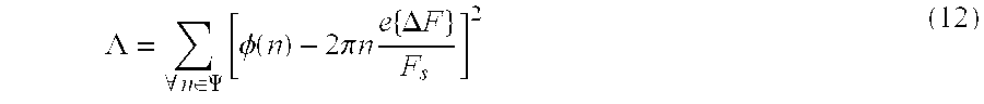
- phase of the actual received synchronization signal y(n), with the initial phase ⁇ set to zero can be represented as:
- ⁇ ⁇ (n) denotes the zero-mean white Gaussian phase noise.
- N 0 samples of the FCB can be grouped into N groups of M phase differences each, and then the sum of each group can be computed.
- block sums of phase differences between successively collected samples of the detected frequency synchronization signal can be used to estimate the frequency offset, rather than individual phase differences between successively collected samples. This reduces the number of calculations required for frequency offset estimation.
- N and M are the number of blocks and the number of samples in each block, respectively.
- the method of linear regression can be modified to compensate for the phase variations without having to shift each sample and keep track of the phase shift in a memory.
- the phase difference between successively collected samples of the FCB can be used for this purpose.
- FIG. 4 illustrates an exemplary apparatus for estimating a frequency offset and a quality factor.
- a detected frequency synchronization signal y(n) is normalized in a Normalizer 400 which limits the dynamic range of the detected signal.
- the Normalizer 400 may be implemented with tables in the same manner as the Normalizer 210 shown in FIG. 2 .
- To obtain an optimal frequency offset estimation ideally only samples of the FCB should be used.
- the received signal can be prefiltered in a frequency selective filter to select the frequency band corresponding to the FCB to discriminate the FCB from noise and thus enhance the signal to noise ratio.
- Each phase difference is added to accumulated previous phase differences by the Sum & Dump Circuit 450 .
- the Sum & Dump Circuit 450 can be implemented by an adder and a filter, such as a FIR filter, with M coefficients set to unity. Alternately, the phase differences can be added by other devices, e.g., an integrate and dump circuit, a resettable integrator, or a low pass filter.
- the sum is “dumped”, i.e., output by the Sum & Dump Circuit 450 to a Frequency Offset Estimation Circuit 460 .
- the Frequency Estimation Circuit 460 computes a weighted sum of groups of phase differences between successively collected samples of the detected frequency synchronization signal to estimate the frequency offset, thus compensating for phase variations between successively collected samples of the frequency synchronization signal, i.e., performing phase unwrapping, without requiring a memory to keep track of phase shifts.
- a Quality Factor Estimation Circuit 470 computes the quality factor estimate e ⁇ according to Equation 20 above. If the estimated quality factor e ⁇ indicates that the estimated frequency offset is not sufficiently accurate, i.e., the estimated quality factor is greater than a predetermined threshold, the estimated frequency offset can be adjusted, e.g., computed again.
- the Quality Factor Estimation Circuit 470 can be implemented with N subtractors for computing N differences between each of the N groups of M phase differences and the estimated frequency offset, N absolute value circuits for computing the absolute values of the N differences, and an adder for adding the N absolute values to produce the estimated quality factor e ⁇ as described in the above mentioned U.S. Pat. No. 6,104,767. Although shown as being separate from the Frequency Offset Estimation Circuit 460 for ease of illustration and explanation, it should be understood that the Quality Factor Estimation Circuit 470 and the Frequency Offset Estimation Circuit 460 can be combined in a single device.
- FIG. 5A illustrates an exemplary method for estimating a frequency offset.
- the method begins at step 500 , at which a received signal is prefiltered to improve detection of the frequency synchronization signal.
- a sample of the detected frequency synchronization signal is collected.
- a successive sample is collected.
- the phase difference between the successively collected samples is computed.
- the phase difference is added to other accumulated phase differences.
- a determination is made whether M phase differences have been added. If not, the process returns to step 520 . If M phase differences have been added, the sum of the M phase differences is dumped at step 560 .
- FIG. 5B illustrates an exemplary method for a estimating quality factor.
- the process starts after the frequency offset has been estimated.
- the estimated frequency offset, weighted by M is subtracted from each of the N sums of M phase differences to produce N differences.
- the absolute values of the N differences are computed.
- the N absolute values are added to produce the estimated quality factor.
- the location of the frequency synchronization signal can be determined based on a detected frequency synchronization signal, synchronized with an estimated frequency offset and quality factor.
- This process can be performed in an apparatus such as that shown in FIG. 6A, which may be included in a receiver, e.g., a mobile station.
- the apparatus includes state memories 620 and 630 .
- the state memory 620 receives a signal representing the detected frequency synchronization signal, e.g., the cross-correlation peak value output by the Moving Averager 245 (shown in FIG. 2 ), and the estimated frequency offset and quality factor values output, e.g., by the Frequency Offset Estimator 460 and the Quality Factor Estimator 470 (shown in FIG. 4 ), respectively. These values are written into the state memory 630 .
- a frequency offset estimation method such as that disclosed in U.S. patent application Ser. No. 6,104,767, decimates the sample rate by M to decrease the number of required parameters for the estimation.
- the rates of the estimated frequency offset and quality factor are one Mth of that of the calculated cross-correlation peak value.
- the apparatus includes a Filter 610 for expanding the rates of the estimated frequency offset and quality factor by M.
- a frequency synchronization signal detection technique such as that described above, delays the in-phase component, resulting in a delay in the calculated cross-correlation peak value.
- FIG. 6B is a graphical representation of peak values, quality factors and frequency offsets over time.
- the peak value is at a maximum greater than or equal to the peak threshold
- the quality factor is at a minimum less than or equal to the quality threshold at a time n 1 .
- This time n 1 corresponds to the location of a frequency synchronization signal.
- the corresponding frequency offset is shown at time n 1 .
- the peak and quality threshold conditions will not be met, i.e., the peak value will be less than the peak threshold, and the quality factor will be greater than the quality threshold.
- the maximum peak value and the minimum quality factor at time n 1 can be used to indicate the location of frequency synchronization signal.
- local extrema including local peak, frequency, and quality values are stored in the state memory 620 .
- the local peak, frequency, and quality values correspond to the calculated cross-correlation peak value, estimated frequency offset, and estimated quality factor.
- the locations of the peak values are also estimated relative to each other by using a Counter 627 in the state memory 620 .
- the Counter 627 counts the number of incoming values, e.g., from the Moving Averager 245 (shown in FIG. 2 ), and from the Frequency Offset Estimator 460 and the Quality Factor Estimator 470 (shown in FIG. 4 ), and is reset when a frequency synchronization signal is detected.
- the count value is stored in the state memory 630 , e.g., in the Delay unit 635 .
- the local extreme values are written as global extreme values, e.g., to a register, and a frequency synchronization signal having the global peak and quality is assumed to be detected. The local extreme values are thereafter reset to zero.
- the corresponding estimated frequency offset is also considered to be the frequency offset between the frequency reference of the mobile station and the carrier frequency of the base station. This frequency offset is used to tune the frequency of the mobile station to the carrier frequency of the base station.
- FIG. 7 illustrates an exemplary method for determining a location of a frequency synchronization signal.
- the method begins at step 700 at which the peak, frequency offset, and quality values are read from the state memory 620 .
- the local peak, frequency offset, and quality values are read from the state memory 630 , e.g., from the Delay unit 635 .
- the counter value is read from the state memory 630 , e.g., from the Delay unit 635 .
- the counter value is updated by adding one to the counter value in the Counter circuit 627 .
- the global peak, frequency offset, and quality values are set equal to zero.
- step 730 it is determined that the cross-correlation peak value is greater than or equal to the peak threshold and the estimated quality factor value is less than or equal to the quality threshold, a determination is made whether the successive peak value read from the memory 620 is greater than the local peak value read from the state memory 630 at step 760 . If so, the local peak, quality factor and frequency offset values are updated at step 765 , and the counter is set to zero at step 775 .
- step 780 the counter value is written to the state memory 630 .
- step 785 the local peak, delay, frequency offset, and quality factor values are written to the state memory 630 , and the process returns to step 700 .
- a method, apparatus, and system are provided for determining the location of a frequency synchronization signal among data transmitted by a transmitter and received by a receiver. This ensures optimal tuning of the receiver to the carrier frequency of the transmitter.
Abstract
Description


Claims (27)
Priority Applications (17)
| Application Number | Priority Date | Filing Date | Title |
|---|---|---|---|
| US09/106,227 US6356608B1 (en) | 1998-06-29 | 1998-06-29 | Method, apparatus, and system for determining a location of a frequency synchronization signal |
| MYPI99002483A MY120816A (en) | 1998-06-29 | 1999-06-16 | Method, apparatus and system for determining a location of a frequency synchronization signal. |
| DE69935072T DE69935072T2 (en) | 1998-06-29 | 1999-06-22 | METHOD, DEVICE AND SYSTEM FOR DETERMINING THE POSITION OF A FREQUENCY SYNCHRONIZATION SIGNAL |
| CN99809916A CN1122380C (en) | 1998-06-29 | 1999-06-22 | Method, apparatus and system for determing location of frequency synchronization signal |
| JP2000557569A JP4149671B2 (en) | 1998-06-29 | 1999-06-22 | Method, apparatus and system for determining the position of a frequency synchronization signal |
| EP99933369A EP1092289B1 (en) | 1998-06-29 | 1999-06-22 | Method, apparatus, and system for determing a location of a frequency synchronization signal |
| EEP200000781A EE200000781A (en) | 1998-06-29 | 1999-06-22 | A method, apparatus, and system for determining the location of a frequency synchronization signal |
| AU49434/99A AU757757B2 (en) | 1998-06-29 | 1999-06-22 | Method, apparatus and system for determining a location of frequency synchronization signal |
| KR1020007014908A KR100614553B1 (en) | 1998-06-29 | 1999-06-22 | Method, apparatus and system for determining a location of a frequency synchronization signal |
| ES99933369T ES2279622T3 (en) | 1998-06-29 | 1999-06-22 | METHOD, APPARATUS AND SYSTEM TO DETERMINE THE POSITION OF A FREQUENCY SYNCHRONIZATION SIGNAL. |
| BR9911714-2A BR9911714A (en) | 1998-06-29 | 1999-06-22 | Method and apparatus for determining a location of a frequency synchronization signal between data transmitted from the transmitter and received by the receiver. |
| AT99933369T ATE353497T1 (en) | 1998-06-29 | 1999-06-22 | METHOD, DEVICE AND SYSTEM FOR DETERMINING THE POSITION OF A FREQUENCY SYNCHRONIZATION SIGNAL |
| TR2001/00371T TR200100371T2 (en) | 1998-06-29 | 1999-06-22 | Method, device and system for determining a location of a frequency synchronization signal |
| IL14040899A IL140408A (en) | 1998-06-29 | 1999-06-22 | Method, apparatus and system for determining a location of a frequency synchronization signal |
| PCT/SE1999/001129 WO2000001095A1 (en) | 1998-06-29 | 1999-06-22 | Method, apparatus and system for determining a location of a frequency synchronization signal |
| ARP990103141A AR019183A1 (en) | 1998-06-29 | 1999-06-29 | METHOD, APPARATUS AND PROVISION TO DETERMINE A LOCATION OF A FREQUENCY SYNCHRONIZATION SIGNAL BETWEEN DATA TRANSMITTED FROM THE TRANSMITTER AND RECEIVED BY THE RECEIVER IN A COMMUNICATIONS NETWORK. |
| HK02101992.4A HK1041122B (en) | 1998-06-29 | 2002-03-14 | Method, apparatus and system for determining a location of a frequency synchronization signal |
Applications Claiming Priority (1)
| Application Number | Priority Date | Filing Date | Title |
|---|---|---|---|
| US09/106,227 US6356608B1 (en) | 1998-06-29 | 1998-06-29 | Method, apparatus, and system for determining a location of a frequency synchronization signal |
Publications (1)
| Publication Number | Publication Date |
|---|---|
| US6356608B1 true US6356608B1 (en) | 2002-03-12 |
Family
ID=22310245
Family Applications (1)
| Application Number | Title | Priority Date | Filing Date |
|---|---|---|---|
| US09/106,227 Expired - Lifetime US6356608B1 (en) | 1998-06-29 | 1998-06-29 | Method, apparatus, and system for determining a location of a frequency synchronization signal |
Country Status (17)
| Country | Link |
|---|---|
| US (1) | US6356608B1 (en) |
| EP (1) | EP1092289B1 (en) |
| JP (1) | JP4149671B2 (en) |
| KR (1) | KR100614553B1 (en) |
| CN (1) | CN1122380C (en) |
| AR (1) | AR019183A1 (en) |
| AT (1) | ATE353497T1 (en) |
| AU (1) | AU757757B2 (en) |
| BR (1) | BR9911714A (en) |
| DE (1) | DE69935072T2 (en) |
| EE (1) | EE200000781A (en) |
| ES (1) | ES2279622T3 (en) |
| HK (1) | HK1041122B (en) |
| IL (1) | IL140408A (en) |
| MY (1) | MY120816A (en) |
| TR (1) | TR200100371T2 (en) |
| WO (1) | WO2000001095A1 (en) |
Cited By (22)
| Publication number | Priority date | Publication date | Assignee | Title |
|---|---|---|---|---|
| US20020151314A1 (en) * | 2001-02-27 | 2002-10-17 | Pioneer Corporation | Positioning apparatus, positioning method, and positioning system |
| US20030112911A1 (en) * | 2001-08-02 | 2003-06-19 | Barton Stephen Kingsley | Method and apparatus for synchronising receivers |
| US6604056B2 (en) * | 2001-02-01 | 2003-08-05 | Drs Power & Control Technologies, Inc. | Method and system of harmonic regulation |
| US20030189978A1 (en) * | 2002-04-09 | 2003-10-09 | Jingdong Lin | Phase difference based frequency correction channel detector for wireless communication system |
| US20030202493A1 (en) * | 2002-04-24 | 2003-10-30 | Jingdong Lin | Bi-directional time slot estimator for wireless communication system |
| US20040014480A1 (en) * | 2002-07-19 | 2004-01-22 | Shang-Chieh Liu | Method and apparatus for frequency synchronization in a digital transmission system |
| US20040072582A1 (en) * | 2002-08-20 | 2004-04-15 | Daniel Aljadeff | Method and system for synchronizing location finding measurements in a wireless local area network |
| US6795428B1 (en) * | 2000-01-07 | 2004-09-21 | Ericsson Inc. | Fast notification access channel for realtime users in EGPRS networks |
| WO2005043852A1 (en) * | 2003-11-03 | 2005-05-12 | Koninklijke Philips Electronics N.V. | Apparatus for determining a frequency offset error and receiver based thereon |
| US20050129149A1 (en) * | 2003-12-12 | 2005-06-16 | Kuntz Thomas L. | Detecting GSM downlink signal frequency correction burst |
| US6937672B1 (en) * | 1999-03-04 | 2005-08-30 | Agere Systems, Inc. | Determining the position of a constant frequency interval in a telecommunication signal |
| US20050238060A1 (en) * | 2004-04-23 | 2005-10-27 | Kuntz Thomas L | Synchronizing to GSM RF downlink signal frame timing |
| WO2005125075A1 (en) * | 2004-06-16 | 2005-12-29 | Telefonaktiebolaget L M Ericsson | Method and apparatus to compensate for receiver frequency error in noise estimation processing |
| US20060023823A1 (en) * | 2004-07-27 | 2006-02-02 | Mediatek Incorporation | Apparatus for frequency synchronization and method for the same |
| US20060044477A1 (en) * | 2004-08-26 | 2006-03-02 | Stmicroelectronics S.A. | Determination of carrier and symbol frequencies in a signal |
| US20060104537A1 (en) * | 2004-11-12 | 2006-05-18 | Sozotek, Inc. | System and method for image enhancement |
| US20060104389A1 (en) * | 1999-12-30 | 2006-05-18 | Infineon Technologies Ag | Configurable all-digital coherent demodulator system for spread spectrum applications |
| US7499423B1 (en) * | 2004-06-10 | 2009-03-03 | Cisco Technology, Inc. (Us) | System and method for clock distribution and synchronization and radio location |
| US20090141781A1 (en) * | 2007-12-03 | 2009-06-04 | Texas Instruments Incorporated | Digital communication using an inexpensive reference crystal |
| US20120108263A1 (en) * | 2009-02-11 | 2012-05-03 | Telefonaktiebolaget L M Ericsson (Publ) | Method and Arrangement for Determining Terminal Position |
| US20150093997A1 (en) * | 2013-09-30 | 2015-04-02 | Broadcom Corporation | Method, Apparatus and Computer Program for Determining Whether a Received Signal Comprises a First Signal Component |
| US9065630B1 (en) * | 2012-09-27 | 2015-06-23 | Marvell International Ltd. | Systems and methods for detecting secondary synchronization signals in a wireless communication system |
Families Citing this family (3)
| Publication number | Priority date | Publication date | Assignee | Title |
|---|---|---|---|---|
| CN102970258B (en) * | 2012-12-11 | 2015-08-12 | 北京北方烽火科技有限公司 | A kind of frequency deviation estimating method and device |
| EP3752846B1 (en) * | 2018-02-16 | 2023-07-12 | Koninklijke Philips N.V. | Improved clock synchronization of a clocked electronic device |
| CN111131106B (en) * | 2018-10-31 | 2022-08-30 | 中国科学院上海高等研究院 | Frequency offset estimation method, system, storage medium and receiving device of communication signal |
Citations (15)
| Publication number | Priority date | Publication date | Assignee | Title |
|---|---|---|---|---|
| US4468625A (en) * | 1981-10-26 | 1984-08-28 | Texas Instruments Incorporated | Circuit for detecting synchronization pulses in a composite signal |
| US4527275A (en) | 1982-02-12 | 1985-07-02 | Arinc Research Corporation | Correlation data communications system |
| EP0387720A1 (en) | 1989-03-16 | 1990-09-19 | Siemens Aktiengesellschaft | Circuit to recognise a reference frequency signal |
| WO1992011706A1 (en) | 1990-12-17 | 1992-07-09 | Motorola, Inc. | Frequency and time slot synchronization using adaptive filtering |
| US5305347A (en) | 1990-09-07 | 1994-04-19 | Deutsche Aerospace Ag | Method of detecting the frequency deviation in digital communication transmissions |
| US5363415A (en) | 1992-02-17 | 1994-11-08 | Nec Corporation | Carrier regenerating device correctly operable in mobile satellite communication |
| US5390216A (en) | 1991-11-02 | 1995-02-14 | Robert Bosch Gmbh | Synchronization method for a mobile radiotelephone |
| JPH07321762A (en) | 1994-05-26 | 1995-12-08 | Nec Corp | Automatic clock frequency control system and transmitter and receiver used for the system |
| EP0717512A2 (en) | 1994-12-16 | 1996-06-19 | AT&T Corp. | Coarse frequency burst detector for a wireless communications systems, such as for use with GSM |
| JPH08331114A (en) | 1995-05-31 | 1996-12-13 | Kokusai Electric Co Ltd | Correlation peak judging circuit |
| JPH0993301A (en) | 1995-09-25 | 1997-04-04 | Nec Corp | Carrier synchronizing unit and synchronizing method |
| GB2315198A (en) | 1996-07-09 | 1998-01-21 | Nec Technologies | GSM time and frequency synchronization using complex correlation of samples of a burst signal |
| US5761250A (en) | 1995-08-15 | 1998-06-02 | Rockwell International Corporation | Iterative filtering frequency estimator and estimation method |
| WO1998024251A2 (en) | 1996-11-27 | 1998-06-04 | Telefonaktiebolaget Lm Ericsson (Publ) | Method for estimating speed of a mobile station in a cellular communications system |
| US6133959A (en) * | 1996-12-31 | 2000-10-17 | Lg Electronics Inc. | Device and method for detecting sync signal from digital TV signal |
-
1998
- 1998-06-29 US US09/106,227 patent/US6356608B1/en not_active Expired - Lifetime
-
1999
- 1999-06-16 MY MYPI99002483A patent/MY120816A/en unknown
- 1999-06-22 EE EEP200000781A patent/EE200000781A/en unknown
- 1999-06-22 AU AU49434/99A patent/AU757757B2/en not_active Ceased
- 1999-06-22 DE DE69935072T patent/DE69935072T2/en not_active Expired - Lifetime
- 1999-06-22 JP JP2000557569A patent/JP4149671B2/en not_active Expired - Fee Related
- 1999-06-22 KR KR1020007014908A patent/KR100614553B1/en not_active IP Right Cessation
- 1999-06-22 ES ES99933369T patent/ES2279622T3/en not_active Expired - Lifetime
- 1999-06-22 BR BR9911714-2A patent/BR9911714A/en not_active IP Right Cessation
- 1999-06-22 TR TR2001/00371T patent/TR200100371T2/en unknown
- 1999-06-22 AT AT99933369T patent/ATE353497T1/en not_active IP Right Cessation
- 1999-06-22 EP EP99933369A patent/EP1092289B1/en not_active Expired - Lifetime
- 1999-06-22 CN CN99809916A patent/CN1122380C/en not_active Expired - Fee Related
- 1999-06-22 WO PCT/SE1999/001129 patent/WO2000001095A1/en active IP Right Grant
- 1999-06-22 IL IL14040899A patent/IL140408A/en not_active IP Right Cessation
- 1999-06-29 AR ARP990103141A patent/AR019183A1/en not_active Application Discontinuation
-
2002
- 2002-03-14 HK HK02101992.4A patent/HK1041122B/en not_active IP Right Cessation
Patent Citations (16)
| Publication number | Priority date | Publication date | Assignee | Title |
|---|---|---|---|---|
| US4468625A (en) * | 1981-10-26 | 1984-08-28 | Texas Instruments Incorporated | Circuit for detecting synchronization pulses in a composite signal |
| US4527275A (en) | 1982-02-12 | 1985-07-02 | Arinc Research Corporation | Correlation data communications system |
| EP0387720A1 (en) | 1989-03-16 | 1990-09-19 | Siemens Aktiengesellschaft | Circuit to recognise a reference frequency signal |
| US5305347A (en) | 1990-09-07 | 1994-04-19 | Deutsche Aerospace Ag | Method of detecting the frequency deviation in digital communication transmissions |
| WO1992011706A1 (en) | 1990-12-17 | 1992-07-09 | Motorola, Inc. | Frequency and time slot synchronization using adaptive filtering |
| US5390216A (en) | 1991-11-02 | 1995-02-14 | Robert Bosch Gmbh | Synchronization method for a mobile radiotelephone |
| US5363415A (en) | 1992-02-17 | 1994-11-08 | Nec Corporation | Carrier regenerating device correctly operable in mobile satellite communication |
| US5596582A (en) | 1994-05-26 | 1997-01-21 | Nec Corporation | AFC in OFDM modulation by shift of a window along a reception sample sequence |
| JPH07321762A (en) | 1994-05-26 | 1995-12-08 | Nec Corp | Automatic clock frequency control system and transmitter and receiver used for the system |
| EP0717512A2 (en) | 1994-12-16 | 1996-06-19 | AT&T Corp. | Coarse frequency burst detector for a wireless communications systems, such as for use with GSM |
| JPH08331114A (en) | 1995-05-31 | 1996-12-13 | Kokusai Electric Co Ltd | Correlation peak judging circuit |
| US5761250A (en) | 1995-08-15 | 1998-06-02 | Rockwell International Corporation | Iterative filtering frequency estimator and estimation method |
| JPH0993301A (en) | 1995-09-25 | 1997-04-04 | Nec Corp | Carrier synchronizing unit and synchronizing method |
| GB2315198A (en) | 1996-07-09 | 1998-01-21 | Nec Technologies | GSM time and frequency synchronization using complex correlation of samples of a burst signal |
| WO1998024251A2 (en) | 1996-11-27 | 1998-06-04 | Telefonaktiebolaget Lm Ericsson (Publ) | Method for estimating speed of a mobile station in a cellular communications system |
| US6133959A (en) * | 1996-12-31 | 2000-10-17 | Lg Electronics Inc. | Device and method for detecting sync signal from digital TV signal |
Non-Patent Citations (1)
| Title |
|---|
| Charbit G. et al., "Frame Synchronization and Frequency-carrier estimation for GSM Mobile Communications", Sep. 30-Oct. 2, 1997 No. 145, pp. 449-457. |
Cited By (50)
| Publication number | Priority date | Publication date | Assignee | Title |
|---|---|---|---|---|
| US6937672B1 (en) * | 1999-03-04 | 2005-08-30 | Agere Systems, Inc. | Determining the position of a constant frequency interval in a telecommunication signal |
| US20100184396A1 (en) * | 1999-12-30 | 2010-07-22 | Infineon Technologies Ag | Configurable all-digital coherent demodulator system for spread spectrum applications |
| US8204161B2 (en) | 1999-12-30 | 2012-06-19 | Intel Mobile Communications GmbH | Configurable all-digital coherent demodulator system for spread spectrum applications |
| US20060104389A1 (en) * | 1999-12-30 | 2006-05-18 | Infineon Technologies Ag | Configurable all-digital coherent demodulator system for spread spectrum applications |
| US8576952B2 (en) | 1999-12-30 | 2013-11-05 | Intel Mobile Communications GmbH | Configurable all-digital coherent demodulator system for spread spectrum applications |
| US7688917B2 (en) | 1999-12-30 | 2010-03-30 | Infineon Technologies Ag | Configurable all-digital coherent demodulator system for spread spectrum applications |
| US6795428B1 (en) * | 2000-01-07 | 2004-09-21 | Ericsson Inc. | Fast notification access channel for realtime users in EGPRS networks |
| US20030212516A1 (en) * | 2001-02-01 | 2003-11-13 | Ulrich James A. | Method and system of harmonic regulation |
| US6681190B2 (en) | 2001-02-01 | 2004-01-20 | Drs Power & Control Technologies, Inc. | Method and system of harmonic regulation |
| US6604056B2 (en) * | 2001-02-01 | 2003-08-05 | Drs Power & Control Technologies, Inc. | Method and system of harmonic regulation |
| US20020151314A1 (en) * | 2001-02-27 | 2002-10-17 | Pioneer Corporation | Positioning apparatus, positioning method, and positioning system |
| US7043257B2 (en) * | 2001-02-27 | 2006-05-09 | Pioneer Corporation | Positioning apparatus, positioning method, and positioning system |
| US7515663B2 (en) * | 2001-08-02 | 2009-04-07 | Mitsubishi Denki Kabushiki Kaisha | Method and apparatus for synchronising receivers |
| US20030112911A1 (en) * | 2001-08-02 | 2003-06-19 | Barton Stephen Kingsley | Method and apparatus for synchronising receivers |
| US20030189978A1 (en) * | 2002-04-09 | 2003-10-09 | Jingdong Lin | Phase difference based frequency correction channel detector for wireless communication system |
| US7110478B2 (en) * | 2002-04-09 | 2006-09-19 | Spreadtrum Communications Corporation | Phase difference based frequency correction channel detector for wireless communication system |
| US20030202493A1 (en) * | 2002-04-24 | 2003-10-30 | Jingdong Lin | Bi-directional time slot estimator for wireless communication system |
| US7092377B2 (en) * | 2002-04-24 | 2006-08-15 | Spreadtrum Communications Corporation | Bi-directional time slot estimator for wireless communication system |
| US20040014480A1 (en) * | 2002-07-19 | 2004-01-22 | Shang-Chieh Liu | Method and apparatus for frequency synchronization in a digital transmission system |
| US7062282B2 (en) | 2002-07-19 | 2006-06-13 | Mediatek, Inc. | Method and apparatus for frequency synchronization in a digital transmission system |
| US6968194B2 (en) * | 2002-08-20 | 2005-11-22 | Aeroscout, Ltd. | Method and system for synchronizing location finding measurements in a wireless local area network |
| US20040072582A1 (en) * | 2002-08-20 | 2004-04-15 | Daniel Aljadeff | Method and system for synchronizing location finding measurements in a wireless local area network |
| CN1879373B (en) * | 2003-11-03 | 2011-01-19 | Nxp股份有限公司 | Apparatus for determining a frequency offset error and receiver based thereon |
| US7733991B2 (en) * | 2003-11-03 | 2010-06-08 | St-Ericsson Sa | Apparatus for determining a frequency offset error and receiver based thereon |
| US20070041479A1 (en) * | 2003-11-03 | 2007-02-22 | Koninklijke Philips Electronics N.V. | Apparatus for determining a frequency offset error and receiver based thereon |
| JP2007511126A (en) * | 2003-11-03 | 2007-04-26 | コーニンクレッカ フィリップス エレクトロニクス エヌ ヴィ | Apparatus for determining frequency offset error and receiver based thereon |
| WO2005043852A1 (en) * | 2003-11-03 | 2005-05-12 | Koninklijke Philips Electronics N.V. | Apparatus for determining a frequency offset error and receiver based thereon |
| JP4807645B2 (en) * | 2003-11-03 | 2011-11-02 | エスティー‐エリクソン、ソシエテ、アノニム | Apparatus for determining frequency offset error and receiver based thereon |
| US20050129149A1 (en) * | 2003-12-12 | 2005-06-16 | Kuntz Thomas L. | Detecting GSM downlink signal frequency correction burst |
| US20050238060A1 (en) * | 2004-04-23 | 2005-10-27 | Kuntz Thomas L | Synchronizing to GSM RF downlink signal frame timing |
| US7957336B2 (en) * | 2004-06-10 | 2011-06-07 | Cisco Technology, Inc. | System and method for clock distribution and synchronization and radio location |
| US20090109956A1 (en) * | 2004-06-10 | 2009-04-30 | Amos James A | System and method for clock distribution and synchronization and radio location |
| US7499423B1 (en) * | 2004-06-10 | 2009-03-03 | Cisco Technology, Inc. (Us) | System and method for clock distribution and synchronization and radio location |
| CN101002418B (en) * | 2004-06-16 | 2010-05-12 | 艾利森电话股份有限公司 | Method and apparatus to compensate for receiver frequency error in noise estimation processing |
| WO2005125075A1 (en) * | 2004-06-16 | 2005-12-29 | Telefonaktiebolaget L M Ericsson | Method and apparatus to compensate for receiver frequency error in noise estimation processing |
| US8934521B2 (en) | 2004-06-16 | 2015-01-13 | Telefonaktiebolaget L M Ericsson (Publ) | Compensating for receiver frequency error in noise estimation processing |
| US20100034331A1 (en) * | 2004-07-27 | 2010-02-11 | Mediatek Incorporation | Frequency synchronization apparatus |
| US20060023823A1 (en) * | 2004-07-27 | 2006-02-02 | Mediatek Incorporation | Apparatus for frequency synchronization and method for the same |
| US7627068B2 (en) | 2004-07-27 | 2009-12-01 | Mediatek Incorporation | Apparatus for frequency synchronization and method for the same |
| US8275086B2 (en) | 2004-07-27 | 2012-09-25 | Mediatek Incorporation | Frequency synchronization apparatus |
| US7865144B2 (en) * | 2004-08-26 | 2011-01-04 | Stmicroelectronics S.A. | Determination of carrier and symbol frequencies in a signal |
| US20060044477A1 (en) * | 2004-08-26 | 2006-03-02 | Stmicroelectronics S.A. | Determination of carrier and symbol frequencies in a signal |
| US20060104537A1 (en) * | 2004-11-12 | 2006-05-18 | Sozotek, Inc. | System and method for image enhancement |
| US20090141781A1 (en) * | 2007-12-03 | 2009-06-04 | Texas Instruments Incorporated | Digital communication using an inexpensive reference crystal |
| US8155600B2 (en) * | 2007-12-03 | 2012-04-10 | Texas Instruments Incorporated | Digital communication using an inexpensive reference crystal |
| US20120108263A1 (en) * | 2009-02-11 | 2012-05-03 | Telefonaktiebolaget L M Ericsson (Publ) | Method and Arrangement for Determining Terminal Position |
| US8914038B2 (en) * | 2009-02-11 | 2014-12-16 | Telefonaktiebolaget L M Ericsson (Publ) | Method and arrangement for determining terminal position |
| US9065630B1 (en) * | 2012-09-27 | 2015-06-23 | Marvell International Ltd. | Systems and methods for detecting secondary synchronization signals in a wireless communication system |
| US20150093997A1 (en) * | 2013-09-30 | 2015-04-02 | Broadcom Corporation | Method, Apparatus and Computer Program for Determining Whether a Received Signal Comprises a First Signal Component |
| US9037092B2 (en) * | 2013-09-30 | 2015-05-19 | Broadcom Corporation | Method, apparatus and computer program for determining whether a received signal comprises a first signal component |
Also Published As
| Publication number | Publication date |
|---|---|
| ATE353497T1 (en) | 2007-02-15 |
| IL140408A (en) | 2005-11-20 |
| DE69935072D1 (en) | 2007-03-22 |
| DE69935072T2 (en) | 2007-06-06 |
| EP1092289B1 (en) | 2007-02-07 |
| HK1041122A1 (en) | 2002-06-28 |
| ES2279622T3 (en) | 2007-08-16 |
| BR9911714A (en) | 2001-03-20 |
| KR20010053243A (en) | 2001-06-25 |
| WO2000001095A1 (en) | 2000-01-06 |
| EP1092289A1 (en) | 2001-04-18 |
| MY120816A (en) | 2005-11-30 |
| AU757757B2 (en) | 2003-03-06 |
| TR200100371T2 (en) | 2001-07-23 |
| CN1314033A (en) | 2001-09-19 |
| AR019183A1 (en) | 2001-12-26 |
| AU4943499A (en) | 2000-01-17 |
| CN1122380C (en) | 2003-09-24 |
| JP4149671B2 (en) | 2008-09-10 |
| IL140408A0 (en) | 2002-02-10 |
| HK1041122B (en) | 2004-06-25 |
| EE200000781A (en) | 2002-04-15 |
| JP2002519935A (en) | 2002-07-02 |
| KR100614553B1 (en) | 2006-08-23 |
Similar Documents
| Publication | Publication Date | Title |
|---|---|---|
| US6356608B1 (en) | Method, apparatus, and system for determining a location of a frequency synchronization signal | |
| US6104767A (en) | Method and apparatus for estimating a frequency offset | |
| US7203254B2 (en) | Method and system for synchronizing in a frequency shift keying receiver | |
| EP0526833B1 (en) | Carrier frequency error detector capable of accurately detecting a carrier frequency error | |
| RU2144733C1 (en) | Signal channel packet for communication system which reference signal id modulated by time- dependent function | |
| JP2751840B2 (en) | Signal detection device | |
| US6266361B1 (en) | Method and architecture for correcting carrier frequency offset and spreading code timing offset in a direct sequence spread spectrum communication system | |
| US6226336B1 (en) | Method and apparatus for detecting a frequency synchronization signal | |
| US6950458B2 (en) | Method and apparatus for acquiring slot timing and frequency offset correction and storage medium storing control program therefor | |
| WO1995004942A1 (en) | Burst tone range processing system and method | |
| US20190207683A1 (en) | Phase noise compensation apparatus, demodulation apparatus, communication apparatus, communication system, and phase noise compensation method | |
| US7315588B2 (en) | System and method for enhanced acquisition for large frequency offsets and poor signal to noise ratio | |
| WO2001086904A1 (en) | Method and apparatus to estimate frequency offset in a receiver | |
| US6662000B1 (en) | Synchronisation method and device for a communication receiver | |
| JP2996941B2 (en) | C / N measurement method and measurement circuit | |
| US20030152179A1 (en) | Method and system for providing a semi-data aided frequency estimator for OQPSK | |
| JP2000307669A (en) | Automatic frequency control system | |
| JPS59183561A (en) | Preamble detector |
Legal Events
| Date | Code | Title | Description |
|---|---|---|---|
| AS | Assignment |
Owner name: TELEFONAKTIEBOLAGET LM ERICSSON, SWEDEN Free format text: ASSIGNMENT OF ASSIGNORS INTEREST;ASSIGNOR:ATARIUS, ROOZBEH;REEL/FRAME:009919/0747 Effective date: 19980729 Owner name: TELEFONAKTIEBOLAGET LM ERICSSON, SWEDEN Free format text: INVALID RECORDING;ASSIGNOR:ATARIUS, ROOZBEH;REEL/FRAME:009461/0674 Effective date: 19980729 |
|
| AS | Assignment |
Owner name: VALAGRO S.P.A., ITALY Free format text: ASSIGNMENT OF ASSIGNORS INTEREST;ASSIGNORS:SEQUI, PAOLO;GOVI, MARCO;CIAVATTA, CLAUDIO;REEL/FRAME:009735/0830 Effective date: 19980121 |
|
| STCF | Information on status: patent grant |
Free format text: PATENTED CASE |
|
| FEPP | Fee payment procedure |
Free format text: PAYOR NUMBER ASSIGNED (ORIGINAL EVENT CODE: ASPN); ENTITY STATUS OF PATENT OWNER: LARGE ENTITY |
|
| FPAY | Fee payment |
Year of fee payment: 4 |
|
| FPAY | Fee payment |
Year of fee payment: 8 |
|
| FPAY | Fee payment |
Year of fee payment: 12 |
|
| AS | Assignment |
Owner name: HIGHBRIDGE PRINCIPAL STRATEGIES, LLC, AS COLLATERA Free format text: LIEN;ASSIGNOR:OPTIS WIRELESS TECHNOLOGY, LLC;REEL/FRAME:032180/0115 Effective date: 20140116 |
|
| AS | Assignment |
Owner name: CLUSTER, LLC, DELAWARE Free format text: ASSIGNMENT OF ASSIGNORS INTEREST;ASSIGNOR:TELEFONAKTIEBOLAGET L M ERICSSON (PUBL);REEL/FRAME:032285/0421 Effective date: 20140116 Owner name: OPTIS WIRELESS TECHNOLOGY, LLC, TEXAS Free format text: ASSIGNMENT OF ASSIGNORS INTEREST;ASSIGNOR:CLUSTER, LLC;REEL/FRAME:032286/0501 Effective date: 20140116 |
|
| AS | Assignment |
Owner name: WILMINGTON TRUST, NATIONAL ASSOCIATION, MINNESOTA Free format text: SECURITY INTEREST;ASSIGNOR:OPTIS WIRELESS TECHNOLOGY, LLC;REEL/FRAME:032437/0638 Effective date: 20140116 |
|
| AS | Assignment |
Owner name: OPTIS WIRELESS TECHNOLOGY, LLC, TEXAS Free format text: RELEASE BY SECURED PARTY;ASSIGNOR:HPS INVESTMENT PARTNERS, LLC;REEL/FRAME:039361/0001 Effective date: 20160711 |