US6357028B1 - Error correction and concealment during data transmission - Google Patents
Error correction and concealment during data transmission Download PDFInfo
- Publication number
- US6357028B1 US6357028B1 US09/272,792 US27279299A US6357028B1 US 6357028 B1 US6357028 B1 US 6357028B1 US 27279299 A US27279299 A US 27279299A US 6357028 B1 US6357028 B1 US 6357028B1
- Authority
- US
- United States
- Prior art keywords
- data
- server
- affected
- digital video
- transmission error
- Prior art date
- Legal status (The legal status is an assumption and is not a legal conclusion. Google has not performed a legal analysis and makes no representation as to the accuracy of the status listed.)
- Expired - Lifetime
Links
Images


Classifications
-
- H—ELECTRICITY
- H04—ELECTRIC COMMUNICATION TECHNIQUE
- H04N—PICTORIAL COMMUNICATION, e.g. TELEVISION
- H04N21/00—Selective content distribution, e.g. interactive television or video on demand [VOD]
- H04N21/60—Network structure or processes for video distribution between server and client or between remote clients; Control signalling between clients, server and network components; Transmission of management data between server and client, e.g. sending from server to client commands for recording incoming content stream; Communication details between server and client
- H04N21/65—Transmission of management data between client and server
- H04N21/658—Transmission by the client directed to the server
-
- H—ELECTRICITY
- H04—ELECTRIC COMMUNICATION TECHNIQUE
- H04L—TRANSMISSION OF DIGITAL INFORMATION, e.g. TELEGRAPHIC COMMUNICATION
- H04L1/00—Arrangements for detecting or preventing errors in the information received
- H04L1/12—Arrangements for detecting or preventing errors in the information received by using return channel
- H04L1/16—Arrangements for detecting or preventing errors in the information received by using return channel in which the return channel carries supervisory signals, e.g. repetition request signals
- H04L1/18—Automatic repetition systems, e.g. Van Duuren systems
- H04L1/1809—Selective-repeat protocols
-
- H—ELECTRICITY
- H04—ELECTRIC COMMUNICATION TECHNIQUE
- H04L—TRANSMISSION OF DIGITAL INFORMATION, e.g. TELEGRAPHIC COMMUNICATION
- H04L1/00—Arrangements for detecting or preventing errors in the information received
- H04L1/12—Arrangements for detecting or preventing errors in the information received by using return channel
- H04L1/16—Arrangements for detecting or preventing errors in the information received by using return channel in which the return channel carries supervisory signals, e.g. repetition request signals
- H04L1/18—Automatic repetition systems, e.g. Van Duuren systems
- H04L1/1829—Arrangements specially adapted for the receiver end
- H04L1/1835—Buffer management
- H04L1/1838—Buffer management for semi-reliable protocols, e.g. for less sensitive applications such as streaming video
-
- H—ELECTRICITY
- H04—ELECTRIC COMMUNICATION TECHNIQUE
- H04N—PICTORIAL COMMUNICATION, e.g. TELEVISION
- H04N19/00—Methods or arrangements for coding, decoding, compressing or decompressing digital video signals
- H04N19/85—Methods or arrangements for coding, decoding, compressing or decompressing digital video signals using pre-processing or post-processing specially adapted for video compression
- H04N19/89—Methods or arrangements for coding, decoding, compressing or decompressing digital video signals using pre-processing or post-processing specially adapted for video compression involving methods or arrangements for detection of transmission errors at the decoder
-
- H—ELECTRICITY
- H04—ELECTRIC COMMUNICATION TECHNIQUE
- H04N—PICTORIAL COMMUNICATION, e.g. TELEVISION
- H04N21/00—Selective content distribution, e.g. interactive television or video on demand [VOD]
- H04N21/60—Network structure or processes for video distribution between server and client or between remote clients; Control signalling between clients, server and network components; Transmission of management data between server and client, e.g. sending from server to client commands for recording incoming content stream; Communication details between server and client
- H04N21/63—Control signaling related to video distribution between client, server and network components; Network processes for video distribution between server and clients or between remote clients, e.g. transmitting basic layer and enhancement layers over different transmission paths, setting up a peer-to-peer communication via Internet between remote STB's; Communication protocols; Addressing
- H04N21/637—Control signals issued by the client directed to the server or network components
- H04N21/6377—Control signals issued by the client directed to the server or network components directed to server
-
- H—ELECTRICITY
- H04—ELECTRIC COMMUNICATION TECHNIQUE
- H04L—TRANSMISSION OF DIGITAL INFORMATION, e.g. TELEGRAPHIC COMMUNICATION
- H04L1/00—Arrangements for detecting or preventing errors in the information received
- H04L2001/0092—Error control systems characterised by the topology of the transmission link
Definitions
- This invention relates to transmitting data from a transmitting terminal to a receiving terminal through a third component, and more particularly to transmitting video data for videoconferencing and video telephony, and error correction and concealment during such transmission.
- Transmitting data by a packet-switched network is one of the most common methods of transmitting data. As with any other type of data transmission, data transmitted by a packet-switched network can be affected by transmission errors such as loss of packets.
- Loss of some packets in a data flow can significantly affect the rest of the data flow. For example, consider the situation where the transmitted data is digital video encoded by a prediction based compression technique. In that case, loss of packets will affect not only a particular frame to which the data in the lost packets belong, but also subsequent frames. In addition, if the compression technique uses motion compensation, then the lost packets will affect not only a particular region in the frames, but also surrounding regions in the subsequent frames, the extent of which depends on the value of the motion vectors. Similarly, if the transmitted data is digital video encoded using variable length coding (for example, Huffman coding), the packet loss can render the information contained in one or more of the subsequent packets unusable.
- variable length coding for example, Huffman coding
- One set of techniques attempt to reduce the effect of packet loss by including redundant control data in all packets. For example, some packetization protocols require control data necessary for decoding a packet to be included in a packet's header, even though the same information is included in a preceding packet.
- Another set of techniques attempt to reduce the effects of lost data on the video image by replacing the lost data with other data. For example, according to one such technique, the lost data is replaced with data from a preceding frame, thereby attempting to improve the image quality of the current frame and reduce errors in subsequently decoded frames. Yet another set of techniques provide methodologies for allowing a receiving terminal to determine whether a packet has been lost and, if so, send a request for a correction of the lost data to the transmitting terminal. The transmitting terminal then provides data which corrects the effects of the lost data. For a summary of various error concealment and correction techniques, see Y. Wang and Q. -F. Zhu, “Error Control and Concealment for Video Communication: A Review,” Proc. IEEE, vol.
- a network switch detects a packet loss and requests a retransmission of the lost packet. The switch does not forward subsequent packets until it receives the replacement packet.
- the delay can have significant negative impact on the displayed video.
- some of the these techniques require that a receiving terminal detect the packet loss.
- error detection at the receiving terminal becomes difficult where the data transmission path includes two networks governed by different protocols because a gateway between the two networks typically removes packet headers from the packets before forwarding the information contained in the packets to the receiving terminal. Removal of the packet headers makes error detection more difficult, since the packet headers typically contain data which can be used for error detection.
- One type of error detection that a receiving terminal can perform is to use its video decoder to detect packet loss errors by checking whether the received video bitstream is in conformance with the bitstream syntax of the encoding algorithm.
- the invention in a general aspect, relates to transmitting data from a transmitting terminal to a receiving terminal through a server.
- the invention features detecting transmission errors in the data at the server and, if an error is detected at the server, sending a request from the server to the transmitting terminal for data correcting the effects of the transmission error on the data affected by the transmission error.
- the affected data is transmitted from the server to the receiving terminal prior to receiving the correction data.
- the invention in another general aspect, relates to a server for receiving data transmitted by a transmitting terminal and transmitting the data to a receiving terminal.
- the server features a receiver receiving data transmitted from the transmitting terminal to the server; a detector detecting transmission errors in the data; a first transmitter sending, if an error is detected, a request to the transmitting terminal for data correcting the effects of the transmission error on the data affected by the transmission error; and a second transmitter transmitting the affected data from the server to the receiving terminal prior to receiving the correction data.
- the invention in yet another aspect, relates to a system including a transmitting terminal, a receiving terminal, and a server, where the transmitting terminal transmits the data to the server and the server transmits the data to the receiving terminal.
- the invention features a server which detects transmission errors in the data, and, in response to certain of such errors, sends a request to the transmitting terminal for data correcting the effects of the transmission error on the data affected by the transmission error.
- the server sends the affected data to the receiving terminal prior to receiving the correction data.
- Preferred embodiments of the invention may include one or more of the following features.
- the server is connected between two networks transmitting data from one network to another.
- the data includes a plurality of packets.
- Data can be digital video or compressed digital video, such as video compressed by a compression technique which uses motion compensation.
- the transmission error can be loss of a packet. Where the transmitted packets are consecutive packets of data identified by sequence numbers, the loss of the packet can be detected by identifying a missing sequence number.
- the server determines the pixels of at least one frame of video affected by the lost packet, and includes in the request sent to the transmitting terminal information identifying at least a portion of the pixels to the transmitting terminal.
- the pixels can be from a single frame or from more than one frame.
- the data received at the server is processed to conceal the detected error from the receiving terminal or other downstream components.
- the process of concealing the error includes modifying the packets such that the transmitted data conforms to that predetermined syntax.
- data can be sent to the receiving terminal to correct the data affected by the transmission error.
- the data is digital video data compressed by a prediction based compression technique, and some of the data is lost
- the digital video data can be compressed, without relying on video data corresponding to data lost during transmission, to provide the data to be sent to correct the data affected by the transmission error.
- the invention may include one or more of the following advantages.
- Embodiments of the invention reduce the time required to recover from transmission errors such as packet loss when transmitting data (for example, video) between two or more terminals.
- some embodiments improve end-to-end video quality when compressed video data is lost or damaged during transmission.
- the transmitting terminal is multi-casting to multiple receiving terminals through a single server, by detecting the error at the server rather than at each of the receiving terminals, only a single error correction request is sent to the transmitting terminal as opposed to multiple requests from the receiving terminals.
- the invention may be implemented in hardware or software, or a combination of both.
- the technique is implemented in computer programs executing on programmable computers that each include a processor, and a storage medium readable by the processor (including volatile and non-volatile memory and/or storage elements).
- Program code is applied to data entered using the input device to perform the functions described above and to generate output information.
- the output information is applied to one or more output devices.
- Each program is preferably implemented in a high level procedural or object oriented programming language to communicate with a computer system.
- the programs can be implemented in assembly or machine language, if desired.
- the language may be a compiled or interpreted language.
- Each such computer program is preferably stored on a storage medium or device (e.g., ROM or magnetic diskette) that is readable by a general or special purpose programmable computer for configuring and operating the computer when the storage medium or device is read by the computer to perform the procedures described in this document.
- a storage medium or device e.g., ROM or magnetic diskette
- the system may also be considered to be implemented as a computer-readable storage medium configured with a computer program, where the storage medium so configured causes a computer to operate in a specific and predefined manner.
- FIG. 1 shows an arrangement of components for transferring digital audio and video from a transmitting terminal to a receiving terminal through a server.
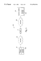
- FIG. 2 shows a block diagram of parts of the server of FIG. 1 .
- FIG. 3 is a schematic diagram of the manner in which a video frame is partitioned according to the ITU-T H.263 standard.
- FIG. 4 schematically illustrates the relationship between positions of two related macroblocks in two consecutive frames and a motion vector characterizing that relationship.
- FIG. 5 is a schematic diagram of the organization of data representing video frames compressed according to the ITU-T H.263 standard.
- FIG. 6 shows a high-level architecture of an RTP packet.
- FIG. 7 is a flow chart of the operation of the server of FIG. 2 .
- FIG. 8 is a flow chart of the steps taken by an error handling program of the server in FIG. 2 to identify the area affected by a detected packet loss.
- FIG. 9 illustrates areas or pixels in video frames affected by lost packets.
- FIG. 1 shows an arrangement of components 100 for transferring digital audio and video from a transmitting terminal 102 to a receiving terminal 104 through a server 110 .
- Terminals 102 and 104 can be videoconferencing units, each having an encoder/decoder 102 A and 104 A, respectively.
- Transmitting terminal 102 is connected to a network 106 , which is a packet switched network.
- Receiving terminal 104 is in turn connected to a network 108 , which can also be a packet switched network.
- Networks 106 and 108 are connected to one another through server 110 which can be a gateway, a multipoint control unit (MCU), or any other network component enabling transfer of data between networks 106 and 108 .
- Each of networks 106 and 108 operates according to a data transmission protocol which is different from the other network's data transmission protocol.
- network 106 can be an Internet Protocol (IP) network
- network 108 can be an Integrated Services Digital Network (ISDN).
- IP Internet Protocol
- ISDN Integrated Services
- FIG. 2 shows a block diagram of components of server 110 .
- Server 110 includes a microprocessor 112 , a memory 114 , a direct memory access (DMA) controller 116 , and a peripheral bus 118 .
- Server 110 also includes two input/output (I/O) ports 120 and 122 connected to peripheral bus 118 .
- I/O ports 120 and 122 are respectively connected to networks 106 and 108 .
- Server 110 also stores a number of application programs in memory 114 , including an error handling program 130 , a data format convertor 128 , and a packet loss detector 126 .
- transmitting terminal 102 transmits data, such as compressed audio and video, to receiving terminal 104 through server 110 .
- server 110 detects transmission errors, namely loss of data packet(s). Once server 110 detects such an error, server 110 performs two operations. First, server 110 sends an error correction request to transmitting terminal 102 so that transmitting terminal 102 can send data to receiving terminal 104 to correct for the lost data. Second, server 110 repairs its output bitstream so that receiver terminal 104 does not detect any errors in the bitstream it receives. In effect, server 110 conceals the packet loss error from receiver terminal 104 . Server 110 , without waiting for a response to its error correction request, forwards the repaired data to receiving terminal 104 .
- server 110 To better understand the operation of server 110 and its components, it is important to first understand the manner in which video is encoded and packetized for transmission from transmitting terminal 102 to receiving terminal 104 .
- ITU International Telecommunications Union
- IP Internet Protocol
- encoder/decoder 102 A of transmitting terminal 102 first compresses a video signal using an encoding algorithm implementing either the ITU Telecommunication Standardization Sector (ITU-T) H.261 standard or the ITU-T H.263 standard. (In the following description, we will describe the embodiments with reference to the H.263 standard.) Transmitting terminal 102 then packetizes the compressed video according to the ITU-T H.225.0 standard which uses the Real-Time Protocol (RTP) of the International Engineering Task Force (IETF). These packets are then transported by an underlying technology supported by network 106 such as User Datagram Protocol/Internet Protocol (UDP/IP).
- ITU-T H.261 the ITU-T H.263 standard.
- RTP Real-Time Protocol
- IETF International Engineering Task Force
- transmitting terminal 102 encapsulates the RTP packets into UDP/IP packets and transmits them to server 110 .
- I/O port 120 of server 110 after receiving the UDP/IP packets, reconstructs the RTP packets before processing the RTP packets or retransmitting them.
- Format convertor 128 of server 110 transforms the RTP packets into a suitable format (for example, the ITU-T H.221 bit stream which is suitable for transmission across an ISDN network) for transmission over network 108 to receiving terminal 104 . There, receiving terminal 104 processes the received packets to recover the video data.
- a frame 300 of video is partitioned into rectangular regions called Groups Of Blocks (GOBs) 305 .
- GOBs Groups Of Blocks
- Each GOB 305 is composed of multiple macroblocks 310 .
- a macroblock 310 contains 4 luminance blocks 315 and 2 chrominance blocks 320 , where each block is a square block of 8 ⁇ 8 pixels.
- video frames can be compressed in two modes: intra mode where the frame is encoded without reliance on other encoded frames, and inter mode where the frame is encoded using inter-frame prediction such that only the prediction error, that is, the difference between the current frame and another encoded frame, is encoded.
- the H.263 standard also uses motion compensation in encoding video data.
- Motion compensation is based on an observation an image in one video frame is often the same as an image in a preceding or a following video frame, except that the image may have moved. For example, two consecutive video frames showing a moving car would have the image of the car, except that the car has moved and its relative location has changed.
- the H.263 standard motion compensation requires matching a macroblock 330 of a frame 335 to a macroblock 340 of a preceding frame 345 , and then determining a value for a motion vector 350 . This value is then included in the encoded video in association with the macroblock.
- FIG. 5 is a representation of data representing a video frame 400 compressed according to the H.263 standard.
- Compressed frame 400 starts with a start code (SC) 405 (here, 16 0-bits followed by a single 1-bit).
- Start code 405 is followed by a frame header 410 .
- Frame header 410 includes such information as frame wide coding mode (for example, whether the frame is inter-frame or intra-frame coded, the H.263 annexes for encoding, etc.).
- Frame header 410 is followed by the GOBs in the frame.
- the first GOB (GOB 0 ) does not have a header field 420 while each of the other GOBs can optionally have a header field.
- Each header field 420 starts with a GOB start code SC 425 and a GOB header 430 .
- GOB header 430 will include such information as a GOB number and a quantization step value used in encoding the first macroblock in that GOB.
- the GOB data follows which includes the data from macroblocks corresponding to that GOB.
- An empty macroblock is stored as a 1 bit flag signaling that the block is empty.
- a non-empty macroblock is encoded and has variable number of bits of data.
- Each macroblock in a GOB will have a macroblock header which will include control data required for decoding that macroblock such as its coding mode, relevant motion vectors, and DCT coefficients.
- the macroblock header of the first macroblock in a GOB having a GOB header stores the actual value of the control data.
- the macroblock headers of the other macroblocks typically store prediction coded values of the control data, which in the described embodiment is the change in value of the control data from the value of the control data of the previous macroblock. However, each macroblock can optionally store the actual (i.e. non-prediction coded) value of these variables.
- FIG. 6 shows a high-level architecture of an RTP packet 500 .
- RTP packet 500 has a header section 505 which contains such information as a sequence number (SN), a time stamp (TS), and a marker bit.
- Sequence numbers (SNs) are consecutive numbers assigned to consecutive RTP packets in an RTP packet stream. If an RTP packet is lost, the sequence numbers of RTP packets arriving at server 110 will not be consecutive.
- the time stamp (TS) field in header section 505 stores the time when a frame was encoded. The time stamp of a video frame is unique to that frame.
- time stamps (TS) are typically used for achieving audio/video synchronization.
- the marker bit in header section 505 indicates whether the RTP packet contains the end of a frame.
- the H.263 payload header 510 contains such information as the frame type (intra-or inter-frame coded), frame format (CIF, QCIF, 4CIF, etc.), and information on whether the RTP packet starts at a GOB boundary or a macroblock boundary. Payload header 510 can also have further information depending on whether the packet is a type ‘A’ or type ‘B’ RTP packet.
- Type ‘B’ RTP packets contain redundant control data from the preceding packet necessary for decoding.
- the redundant control data consists of control data from the GOB header of the last GOB and from the macroblock header of the last macroblock in the preceding RTP packet.
- the redundant control data includes the motion vector predictor, the quantization step size, and the address of the first macroblock in the current RTP packet.
- type ‘B’ RTP packets allow decoding the first macroblock without resorting to information contained in the previous RTP packet, in case that previous RTP packet is lost.
- Type ‘A’ RTP packets do not contain such redundant control data in their headers.
- Encoder/decoder 102 A of transmitting terminal 102 determines whether an RTP packet will be of type ‘A’ or type ‘B’ depending on the video data to be included in the packet. There are three cases: video data starts at the beginning of a GOB having a header; video data starts at the beginning of a GOB not having a header; and video data starts at a macroblock boundary (that is, not at a GOB boundary). In the case of video data starting at a GOB having a header, RTP packet will be packetized as a type ‘A’ packet since information required for decoding the data will be in the GOB header.
- RTP packet can be packetized as either a type ‘A’ or type ‘B’ packet.
- the packet would be packetized as a type ‘B’ packet, since the information for decoding the video data depends on information in the previous packet.
- RTP packet will be packetized as a type ‘B’ packet.
- the H.263 payload 515 of RTP packet 500 contains the encoded video data, such as compressed video frame 400 shown in FIG. 5 .
- I/O port 120 receives from network 106 UDP/IP packets from which I/O port 120 reconstructs RTP packets.
- I/O port 120 indicates the receipt of the RTP packet to DMA Controller 116 .
- DMA controller 116 stores the RTP packet in a current packet buffer, replacing a previously stored frame in that buffer.
- DMA controller 116 also transfers the previously stored RTP packet to a preceding packet buffer (step 210 ).
- Packet loss detector 126 determines whether any RTP packet has been lost since the receipt of the preceding RTP packet (step 215 ). To do so, packet loss detector 126 compares the sequence number of the RTP packet stored in the current packet buffer with the sequence number of the RTP packet stored in the preceding packet buffer. If the sequence numbers are not consecutive, packet loss detector 126 determines that one or more RTP packets have been lost.
- packet loss detector 126 indicates to format convertor 128 to prepare the RTP packet for transmission over network 108 to receiving terminal 104 .
- Format convertor 128 converts RTP packets received from network 106 into a format acceptable to network 108 (step 220 ). For example, if network 108 is an ISDN network, format convertor 128 depacketizes the video data into an ITU-T H.221 bit stream packets for network 108 . Format conversion often entails removing the RTP Header and payload header from the received data. Upon conversion, format convertor 128 transfers the packets to I/O port 122 for transmission (step 225 ).
- microprocessor 112 executes error handling program 130 .
- Error handling program 130 determines the area (that is, pixels) which were represented by the data in the lost RTP packet(s) (step 230 ). Error handling program 130 then sends an error correction request to transmitting terminal 102 (step 235 ). Error handling program 130 also conceals the packet loss error from downstream components, namely receiving terminal 104 (step 240 ). To do so, error handling program 130 repairs the bit stream transmitted downstream so that it conforms to the H.263 syntax for encoded video data.
- receiving terminal 104 detects packet loss errors in the bitstream by determining whether the received data conforms to the H.263 syntax for encoded video data, receiving terminal 104 does not detect any transmission errors.
- error handling program 130 transfers the repaired bitstream to format convertor 128 for conversion and then transmission over network 108 (step 220 ). The operation of error handling program 130 will now be described in further detail below.
- error handling program 130 as discussed in reference to step 230 in FIG. 7, first determines the pixels in the current frame, and any preceding frame(s) frame, whose data is contained in the lost RTP packet(s) (hereinafter, also referred to as the “affected area”).
- FIG. 8 is a flow chart of the steps taken by error handling program 130 to determine the affected area. These steps can be divided into two functional categories. First, in steps 605 - 610 , error handling program 130 determines whether the affected area is confined to one frame (hereinafter, “intra-frame damage”) or extends across two or more frames (hereinafter, “inter-frame damage”). Referring also to FIG. 9, if the damage is an intra-frame damage, then a starting point 750 and an ending point 755 of an affected area 760 will be in the same frame 765 . If the damage is an inter-frame damage, then starting point 750 and ending point 755 of affected area 760 will be in different frames 770 and 775 . Note that, whether the damage is intra-frame or inter-frame, the starting point will be immediately after the end of the preceding packet. Similarly, whether the damage is intra-frame or inter-frame, the ending point will be immediately before the start of current packet.
- step 615 error handling program 130 determines the starting and ending points of the affected area, so that the area can be identified to transmitting terminal 102 in an error correction request (FIG. 6, step 235 ). The steps taken by error handling program 130 to perform these two functions will now be described in detail.
- error handling program 130 determines whether the damage is an intra-frame damage or inter-frame damage. In doing so, error handling program 130 uses the marker bits and time stamps of the preceding and current RTP packets. Error handling program 130 first, in step 605 , determines whether the time stamps of the preceding and current RTP packets are the same (i.e. both RTP packets belong to the same frame). If so, error handling program 130 determines that the damage is an intra-frame damage. Otherwise, error handling program 130 checks the marker bit of the preceding RTP packet (step 610 ). If the marker bit is set to 1, then the preceding RTP packet contains the end of a frame.
- error handling program 130 determines that the damage is an intra-frame damage. If the marker bit of the preceding RTP packet is set to 0 (i.e., the RTP packet does not contain the end of a frame), then error handling program 130 determines that the damage is an inter-frame damage. Note that it should never be the case that the marker bit of the preceding RTP packet is set to 1 and that the time stamps of the preceding and the current RTP packet are the same, since that would indicate that time stamps of two different frames are the same. That would be an error.
- Error handling program 130 next determines the starting point and the ending point of the affected area in each video frame affected by the packet loss (step 615 ).
- Error handling program 130 identifies the starting point and the ending point of the affected area by identifying the lost and damaged macroblocks. Error handling program 130 identifies the lost and damaged macroblocks by their Macroblock Addresses (MBA).
- An MBA is a number assigned to each macroblock in a frame according to the position of that macroblock in that frame. The MBA numbers proceed from MBA 0 to MBA max in each frame, with macroblock MBA 0 being located in the upper, left corner of the frame and macroblock MBA max being located in the lower, right corner of the frame. MBA value numbers consecutively increase in the standard video scan order—left to right, top to bottom.
- the macroblock address of a macroblock is determined by multiplying the GOB number of an immediately preceding GOB header by the standard number of macroblocks in each GOB, then counting the number of macroblocks between the GOB header and the macroblock of interest, and finally adding the two numbers together to obtain the desired MBA.
- error handling program 130 determines the starting point's MBA (MBA start ) and the ending point's MBA (MBA end ) for the damaged area.
- the process for determining the MBA start and MBA end in the case of intra-frame damages and inter-frame damages are the same except for one thing: for an inter-frame damage, MBA start and MBA end are in two different frames.
- error handling program 130 determines whether the marker bit for the preceding RTP packet is set to 1 or 0. If set to 1, then the preceding RTP packet represents the end of the previous frame. Since each RTP packet contains data only from one video frame, error handling program 130 determines MBA start to be MBA 0 of the subsequent frame. In the described embodiment, it is assumed that only one frame can be lost and therefore, it is assumed that MBA start is MBA 0 of the current frame.
- error handling program 130 finds the address of the last complete macroblock contained in the preceding RTP packet. To do so, error handling program 130 processes the RTP packet beginning from the end of the preceding RTP packet and proceeding to the start of the preceding RTP packet. Error handling program 130 finds the position of the last received GOB start code. Error handling program 130 then uses the GOB number to determine the MBA for the first macroblock after the GOB header from the GOB number contained in the GOB header. Error handling program 130 then decodes the GOB according to the H.263 encoding syntax to parse the bits between the GOB header and the end of the preceding RTP packet so as to determine the MBA of the last macroblock in the RTP packet. MBA start is set to be this determined MBA plus one.
- error handling program 130 determines MBA end by processing the current RTP packet. If the current RTP packet is aligned with a GOB header, then MBA end is easily derived from the GOB number in the GOB header. If the current RTP packet is not aligned with a GOB header and the RTP packet is a type ‘B’ RTP packet, then the MBA end is obtained from the H.263 payload header which stores the MBA of the first macroblock of the current RTP packet. If the current RTP packet is aligned with a GOB header and the RTP packet is a type ‘A’ RTP packet, then the MBA end is set to be the MBA of the first macroblock following the first GOB start code in the current RTP packet.
- error handling program 130 then performs two steps (steps 235 and 240 ): send an error correction request to transmitting terminal 102 and repair the outgoing bit stream so that it appears to receiving terminal 104 (or other downstream components) as not being affected by packet loss.
- steps 235 and 240 send an error correction request to transmitting terminal 102 and repair the outgoing bit stream so that it appears to receiving terminal 104 (or other downstream components) as not being affected by packet loss.
- the error correction request sent by error handling program 130 indicates to transmitting terminal 102 that a packet loss has occurred and also identifies lost pixels identifying the lost macroblocks.
- the request includes a frame index value which identifies the current frame to transmitting terminal 102 , MBA start , and MBA end .
- frame index values are referred to as Temporal References (TR) and are the time stamps of the frames.
- TR Temporal References
- two requests are sent: one for the preceding frame, identifying the damaged macroblocks therein (a frame index value for the preceding frame, MBA start , MBA max ); and one for the current frame (a frame index value for the current frame, MBA 0 , MBA end ).
- transmitting terminal 102 Being supplied with this information, rather than encoding an entire frame in intra mode (that is, generate an I-frame), transmitting terminal 102 identifies the affected macroblocks and performs error correction techniques which do not require encoding an entire intra mode frame. Such error correction techniques require less data to be sent to receiving terminal 104 to enable receiving terminal 104 to correct for packet loss. Because less data need be transmitted to correct for packet loss errors, problems such as worse frame quality, reduced frame rate, and momentarily frozen images are at least reduced, and possibly avoided altogether.
- transmitting terminal 102 re-encodes the video data to be sent without using data representing the area (that is, pixels) identified in the error correction request message.
- the video data is encoded without being predicted based on the lost (or damaged) macroblocks.
- the decoded video data will not have any errors associated with the data in the lost macroblocks, since the data is not encoded using the data in those macroblocks.
- transmitting terminal 102 stops encoding and packetizing the video data. Transmitting terminal 102 then uses the information in the error correction request to identify the lost macroblocks. Encoder/decoder 102 A then re-encodes the already sent video, starting at some point at or before the first lost macroblock, without using the lost data. Transmitting terminal 102 then recommences packetizing the re-encoded data for transmission, starting at the macroblock immediately after the last macroblock sent to receiving terminal 104 . For a more detailed description of this error correction technique, see W. Wada, “Selective recovery of video packet loss using error concealment,” IEEE J. Select.
- An alternative error correction technique that can be used is the H.263 error tracking technique (see ITU-T Recommendation H.263, Video Coding for Low Bitrate Communication, 1998).
- error handling program 130 also repairs the outgoing bit stream so that the output bitstream is restored to a legal bitstream according to the H.263 encoding syntax. Thus, to receiving terminal 104 , the bitstream appears not to be affected by any transmission errors.
- error handling program 130 performs two functions. First, error handling program 130 generates an ITU-T H.221 bit stream containing “empty” macroblocks corresponding to the lost macroblocks which were previously identified. For example, the error handling program 130 generates appropriate GOB headers together with data representing empty macroblocks. In the case of H.263, such macroblocks would have a coded/unencoded (COD) bit, which would be set to indicate that the blocks are unencoded.
- COD coded/unencoded
- error handling program 130 uses the information in the RTP header from the current packet to convert prediction coded control data, such as the first macroblock's motion vector, into their actual values.
- prediction coded control data such as the first macroblock's motion vector
- more than one server may be located between the transmitting terminal 102 and receiving terminal 104 .
- each of the servers can perform error correction and concealment in the manner described here.
- another server downstream preferably does not detect the same error.
- the downstream server will detect errors which occur during transmission between the two servers.
- one or more of these servers may form part of a network, such as network 106 or 108 . In that case, the entire data path between transmitting terminal 102 and receiving terminal 104 can be within the same network.
- the techniques described here can be used for transmission and receipt of two-way, interactive videoconferencing and video telephony.
- the techniques can also be used for internet video streaming.
- terminals 102 and 104 are described as being videoconferencing or video telephone systems. However, these techniques can also be used for transfer of other types of data and for other applications.
Abstract
Description
Claims (45)
Priority Applications (1)
| Application Number | Priority Date | Filing Date | Title |
|---|---|---|---|
| US09/272,792 US6357028B1 (en) | 1999-03-19 | 1999-03-19 | Error correction and concealment during data transmission |
Applications Claiming Priority (1)
| Application Number | Priority Date | Filing Date | Title |
|---|---|---|---|
| US09/272,792 US6357028B1 (en) | 1999-03-19 | 1999-03-19 | Error correction and concealment during data transmission |
Publications (1)
| Publication Number | Publication Date |
|---|---|
| US6357028B1 true US6357028B1 (en) | 2002-03-12 |
Family
ID=23041299
Family Applications (1)
| Application Number | Title | Priority Date | Filing Date |
|---|---|---|---|
| US09/272,792 Expired - Lifetime US6357028B1 (en) | 1999-03-19 | 1999-03-19 | Error correction and concealment during data transmission |
Country Status (1)
| Country | Link |
|---|---|
| US (1) | US6357028B1 (en) |
Cited By (52)
| Publication number | Priority date | Publication date | Assignee | Title |
|---|---|---|---|---|
| US20010033657A1 (en) * | 2000-01-18 | 2001-10-25 | Lipton Richard J. | Method and systems for identifying the existence of one or more unknown programs in a system |
| US20020013696A1 (en) * | 2000-05-23 | 2002-01-31 | Toyokazu Hama | Voice processing method and voice processing device |
| US20020021752A1 (en) * | 2000-05-15 | 2002-02-21 | Miska Hannuksela | Video coding |
| US20020090086A1 (en) * | 2000-12-18 | 2002-07-11 | Van Rijnsoever Bartholomeus Johannes | Pointers to encrypted data in RTP header |
| US20020152440A1 (en) * | 2000-10-27 | 2002-10-17 | Ilan Yona | Apparatus and method for improving the quality of video communication over a packet-based network |
| US20020194603A1 (en) * | 2001-06-15 | 2002-12-19 | Jay H. Connelly | Method and apparatus to distribute content using a multi-stage broadcast system |
| US20030005465A1 (en) * | 2001-06-15 | 2003-01-02 | Connelly Jay H. | Method and apparatus to send feedback from clients to a server in a content distribution broadcast system |
| US20030005451A1 (en) * | 2001-06-15 | 2003-01-02 | Connelly Jay H. | Method and apparatus to distribute content descriptors in a content distribution broadcast system |
| US20030016673A1 (en) * | 2001-06-29 | 2003-01-23 | Ramesh Pendakur | Correcting for data losses with feedback and response |
| US20030035487A1 (en) * | 2001-08-16 | 2003-02-20 | Sony Corporation And Sony Electronic Inc. | Error concealment of video data using texture data recovery |
| US20030066090A1 (en) * | 2001-09-28 | 2003-04-03 | Brendan Traw | Method and apparatus to provide a personalized channel |
| US20030157761A1 (en) * | 1999-12-27 | 2003-08-21 | Fujitsu Limited | Method for forming bumps, semiconductor device, and solder paste |
| US20030163829A1 (en) * | 2002-02-22 | 2003-08-28 | Qwest Communications International Inc. | Systems and methods for providing redundant back-up to a video transmission system |
| US20030182454A1 (en) * | 2000-07-25 | 2003-09-25 | Hans-Peter Huth | Header compression method for network protocols |
| US6658618B1 (en) * | 1999-09-02 | 2003-12-02 | Polycom, Inc. | Error recovery method for video compression coding using multiple reference buffers and a message channel |
| US6683909B1 (en) * | 2000-03-16 | 2004-01-27 | Ezenial Inc. | Macroblock parsing without processing overhead |
| US20040028039A1 (en) * | 2002-08-06 | 2004-02-12 | Kai Miao | Communicating tone information in a network |
| US6934280B1 (en) * | 2000-05-04 | 2005-08-23 | Nokia, Inc. | Multiple services emulation over a single network service |
| US20060028948A1 (en) * | 2004-08-05 | 2006-02-09 | Batchelor Gary W | Apparatus and method to overlay (N) first sectors onto (M) second sectors using a data queue |
| US20060045017A1 (en) * | 2004-08-26 | 2006-03-02 | Nec Corporation | Network-quality determining method and apparatus for use therewith |
| US20060083182A1 (en) * | 2004-10-15 | 2006-04-20 | Tracey Jonathan W | Capability management for automatic dialing of video and audio point to point/multipoint or cascaded multipoint calls |
| US20060106929A1 (en) * | 2004-10-15 | 2006-05-18 | Kenoyer Michael L | Network conference communications |
| US20060122823A1 (en) * | 2004-11-24 | 2006-06-08 | Samsung Electronics Co., Ltd. | Method and apparatus for processing asynchronous audio stream |
| US20060256738A1 (en) * | 2004-10-15 | 2006-11-16 | Lifesize Communications, Inc. | Background call validation |
| US20070079324A1 (en) * | 2001-05-11 | 2007-04-05 | Hallford Jason C | Method and apparatus for combining broadcast schedules and content on a digital broadcast-enabled client platform |
| US7231545B2 (en) * | 2004-08-05 | 2007-06-12 | International Business Machines Corporation | Apparatus and method to convert data from a first sector format to a second sector format |
| US7240242B2 (en) * | 2004-08-05 | 2007-07-03 | International Business Machines Corporation | Apparatus and method to convert data payloads from a first sector format to a second sector format |
| US20080022008A1 (en) * | 2000-03-21 | 2008-01-24 | Connelly Jay H | Method and apparatus to determine broadcast content and scheduling in a broadcast system |
| US20080240123A1 (en) * | 2007-03-27 | 2008-10-02 | Cisco Technology, Inc. | Method and system for communicating h.263 macroblock boundaries using h.221 bas for rfc2190-compliant fragmentation |
| US20090037958A1 (en) * | 2001-09-28 | 2009-02-05 | Brendan Traw | Method and apparatus to provide a personalized channel |
| US20090079811A1 (en) * | 2007-09-20 | 2009-03-26 | Brandt Matthew K | Videoconferencing System Discovery |
| US20090245283A1 (en) * | 2006-08-29 | 2009-10-01 | Macdonald Boyce Jill | Method and apparatus for repairing samples included in container files having lost packets |
| US20100104024A1 (en) * | 2008-10-29 | 2010-04-29 | At&T Intellectual Property I, L.P. | Remediation of television signals using a network back-channel |
| US7827458B1 (en) * | 2003-03-03 | 2010-11-02 | Apple Inc. | Packet loss error recovery |
| US20100328421A1 (en) * | 2009-06-29 | 2010-12-30 | Gautam Khot | Automatic Determination of a Configuration for a Conference |
| US7971121B1 (en) * | 2004-06-18 | 2011-06-28 | Verizon Laboratories Inc. | Systems and methods for providing distributed packet loss concealment in packet switching communications networks |
| US20120033739A1 (en) * | 2004-08-20 | 2012-02-09 | Polycom, Inc. | Error Concealment In A Video Decoder |
| US20120287999A1 (en) * | 2011-05-11 | 2012-11-15 | Microsoft Corporation | Syntax element prediction in error correction |
| US8775889B2 (en) * | 2001-12-21 | 2014-07-08 | Lambert Everest Limited | Adaptive error resilience for packet transmission over a network |
| US8850467B1 (en) | 2013-03-15 | 2014-09-30 | International Business Machines Corporation | System and method for monitoring video performance |
| US20140341202A1 (en) * | 2011-10-07 | 2014-11-20 | Andrew J. Patti | Communication Over A Wireless Connection |
| US9264737B2 (en) | 2012-10-01 | 2016-02-16 | Apple Inc. | Error resilient transmission of random access frames and global coding parameters |
| US9326041B2 (en) | 2013-09-17 | 2016-04-26 | International Business Machines Corporation | Managing quality of experience for media transmissions |
| US9332309B2 (en) | 2012-06-08 | 2016-05-03 | Apple Inc. | Sync frame recovery in real time video transmission system |
| US9491487B2 (en) | 2012-09-25 | 2016-11-08 | Apple Inc. | Error resilient management of picture order count in predictive coding systems |
| US9819953B2 (en) | 2013-12-31 | 2017-11-14 | International Business Machines Corporation | Decoding media streams within thresholds |
| US20210176506A1 (en) * | 2014-07-31 | 2021-06-10 | Lg Electronics Inc. | Apparatus and method for transmitting/receiving processes of a broadcast signal |
| US20220255866A1 (en) * | 2020-04-02 | 2022-08-11 | Boe Technology Group Co., Ltd. | Audio/video communication method, terminal, server, computer device, and storage medium |
| US20220368440A1 (en) * | 2021-05-03 | 2022-11-17 | Arris Enterprises Llc | System for channel map delivery for hi split cable networks |
| US11528521B2 (en) * | 2020-12-01 | 2022-12-13 | Arris Enterprises Llc | Partial video async support using R-MACPHY device |
| US11533526B2 (en) * | 2021-02-01 | 2022-12-20 | Arris Enterprises Llc | Adaptive video slew rate for video delivery |
| US11700402B1 (en) * | 2022-03-25 | 2023-07-11 | Nvidia Corporation | Dynamically reducing stutter and latency in video streaming applications |
Citations (13)
| Publication number | Priority date | Publication date | Assignee | Title |
|---|---|---|---|---|
| US3979719A (en) * | 1973-04-02 | 1976-09-07 | Texas Instruments Incorporated | Multiple block binary synchronous duplex communications system and its method of operation |
| US5036518A (en) * | 1988-11-02 | 1991-07-30 | Tseung Lawrence C N | Guaranteed reliable broadcast network |
| US5550847A (en) * | 1994-10-11 | 1996-08-27 | Motorola, Inc. | Device and method of signal loss recovery for realtime and/or interactive communications |
| US5577172A (en) * | 1994-07-01 | 1996-11-19 | Lasermaster Corporation | High-capacity protocol for packet-based networks |
| US5680322A (en) * | 1994-05-30 | 1997-10-21 | Matsushita Electric Industrial Co., Ltd. | Method and apparatus for dynamic image data transmission |
| US5864654A (en) * | 1995-03-31 | 1999-01-26 | Nec Electronics, Inc. | Systems and methods for fault tolerant information processing |
| US5918002A (en) * | 1997-03-14 | 1999-06-29 | Microsoft Corporation | Selective retransmission for efficient and reliable streaming of multimedia packets in a computer network |
| US5968197A (en) * | 1996-04-01 | 1999-10-19 | Ericsson Inc. | Method and apparatus for data recovery |
| US6032180A (en) * | 1996-09-26 | 2000-02-29 | Fujitsu Limited | Image data transmission system, video server unit, and client unit for displaying image data |
| US6104757A (en) * | 1998-05-15 | 2000-08-15 | North Carolina State University | System and method of error control for interactive low-bit rate video transmission |
| US6141785A (en) * | 1997-10-06 | 2000-10-31 | Electronics And Telecommunications Research Institute | Error control method for multiparty multimedia communications |
| US6173317B1 (en) * | 1997-03-14 | 2001-01-09 | Microsoft Corporation | Streaming and displaying a video stream with synchronized annotations over a computer network |
| US6230296B1 (en) * | 1998-04-20 | 2001-05-08 | Sun Microsystems, Inc. | Method and apparatus for providing error correction |
-
1999
- 1999-03-19 US US09/272,792 patent/US6357028B1/en not_active Expired - Lifetime
Patent Citations (13)
| Publication number | Priority date | Publication date | Assignee | Title |
|---|---|---|---|---|
| US3979719A (en) * | 1973-04-02 | 1976-09-07 | Texas Instruments Incorporated | Multiple block binary synchronous duplex communications system and its method of operation |
| US5036518A (en) * | 1988-11-02 | 1991-07-30 | Tseung Lawrence C N | Guaranteed reliable broadcast network |
| US5680322A (en) * | 1994-05-30 | 1997-10-21 | Matsushita Electric Industrial Co., Ltd. | Method and apparatus for dynamic image data transmission |
| US5577172A (en) * | 1994-07-01 | 1996-11-19 | Lasermaster Corporation | High-capacity protocol for packet-based networks |
| US5550847A (en) * | 1994-10-11 | 1996-08-27 | Motorola, Inc. | Device and method of signal loss recovery for realtime and/or interactive communications |
| US5864654A (en) * | 1995-03-31 | 1999-01-26 | Nec Electronics, Inc. | Systems and methods for fault tolerant information processing |
| US5968197A (en) * | 1996-04-01 | 1999-10-19 | Ericsson Inc. | Method and apparatus for data recovery |
| US6032180A (en) * | 1996-09-26 | 2000-02-29 | Fujitsu Limited | Image data transmission system, video server unit, and client unit for displaying image data |
| US5918002A (en) * | 1997-03-14 | 1999-06-29 | Microsoft Corporation | Selective retransmission for efficient and reliable streaming of multimedia packets in a computer network |
| US6173317B1 (en) * | 1997-03-14 | 2001-01-09 | Microsoft Corporation | Streaming and displaying a video stream with synchronized annotations over a computer network |
| US6141785A (en) * | 1997-10-06 | 2000-10-31 | Electronics And Telecommunications Research Institute | Error control method for multiparty multimedia communications |
| US6230296B1 (en) * | 1998-04-20 | 2001-05-08 | Sun Microsystems, Inc. | Method and apparatus for providing error correction |
| US6104757A (en) * | 1998-05-15 | 2000-08-15 | North Carolina State University | System and method of error control for interactive low-bit rate video transmission |
Non-Patent Citations (12)
| Title |
|---|
| Cote et al., "H.263+: Video Coding at Low Bit Rates," Department of Electrical and Computer Engineering, University of British Columbia, pp. 1-41. |
| DataBeam, "A Primer on the H.323 Series Standard", May 1998. |
| International Telecommunication Union, "ITU-T Recommendation H.263", Nov. 95. |
| Schulzrinne et al., "RTP: A Transport Protocol for Real-Time Applications," Network Working Group, RFC 1889, Jan. 96. |
| Schulzrinne et al., "RTP: Profile for Audio and Video Conferences with Minimal Control," Network Working Group, RFC 1890, Jan. 96. |
| Trillium, "H.323 Tutorial" Dec. 2, 1998. |
| Turletti et al., "RTP packetization of H.261 video streams", Internet Engineering Task Force, Audio-Video Transport WG, Mar. 1995. |
| Turletti et al., "RTP payload format for H.261 video streams," Internet Engineering Task Force, Audio-Video Transport WG, Jul. 10, 1995. |
| Wada, "Selective Recovery of Video Packet Loss Using Error Concealment", IEEE Journal on Selected Areas in Communications, pp. 807-814, 1989. |
| Wada, Mashiro, "Selective Recovery of Video Packer Loss Using Error Concelament', IEEE Journal on Selected Areas in Communications, vol. 7, No. 5, Jun. 1989.* |
| Wada, Mashiro, ‘Selective Recovery of Video Packer Loss Using Error Concelament’, IEEE Journal on Selected Areas in Communications, vol. 7, No. 5, Jun. 1989.* |
| Wang et al., "Error Control and Concealment for Video Communication: A Review", Proceedings of the IEEE, vol. 86., No. 5, pp. 974-997, May 1998. |
Cited By (92)
| Publication number | Priority date | Publication date | Assignee | Title |
|---|---|---|---|---|
| US6658618B1 (en) * | 1999-09-02 | 2003-12-02 | Polycom, Inc. | Error recovery method for video compression coding using multiple reference buffers and a message channel |
| US20030157761A1 (en) * | 1999-12-27 | 2003-08-21 | Fujitsu Limited | Method for forming bumps, semiconductor device, and solder paste |
| US20010033657A1 (en) * | 2000-01-18 | 2001-10-25 | Lipton Richard J. | Method and systems for identifying the existence of one or more unknown programs in a system |
| US6683909B1 (en) * | 2000-03-16 | 2004-01-27 | Ezenial Inc. | Macroblock parsing without processing overhead |
| US7962573B2 (en) | 2000-03-21 | 2011-06-14 | Intel Corporation | Method and apparatus to determine broadcast content and scheduling in a broadcast system |
| US20080022008A1 (en) * | 2000-03-21 | 2008-01-24 | Connelly Jay H | Method and apparatus to determine broadcast content and scheduling in a broadcast system |
| US8839298B2 (en) | 2000-03-21 | 2014-09-16 | Intel Corporation | Method and apparatus to determine broadcast content and scheduling in a broadcast system |
| US8108542B2 (en) | 2000-03-21 | 2012-01-31 | Intel Corporation | Method and apparatus to determine broadcast content and scheduling in a broadcast system |
| US6934280B1 (en) * | 2000-05-04 | 2005-08-23 | Nokia, Inc. | Multiple services emulation over a single network service |
| US8144764B2 (en) | 2000-05-15 | 2012-03-27 | Nokia Oy | Video coding |
| US20020021752A1 (en) * | 2000-05-15 | 2002-02-21 | Miska Hannuksela | Video coding |
| US20060029129A1 (en) * | 2000-05-15 | 2006-02-09 | Miska Hannuksela | Video Coding |
| US6968005B2 (en) * | 2000-05-15 | 2005-11-22 | Nokia Mobile Phones Limited | Video coding |
| US20020013696A1 (en) * | 2000-05-23 | 2002-01-31 | Toyokazu Hama | Voice processing method and voice processing device |
| US7127399B2 (en) * | 2000-05-23 | 2006-10-24 | Ntt Docomo, Inc. | Voice processing method and voice processing device |
| US20030182454A1 (en) * | 2000-07-25 | 2003-09-25 | Hans-Peter Huth | Header compression method for network protocols |
| US20020152440A1 (en) * | 2000-10-27 | 2002-10-17 | Ilan Yona | Apparatus and method for improving the quality of video communication over a packet-based network |
| US20020090086A1 (en) * | 2000-12-18 | 2002-07-11 | Van Rijnsoever Bartholomeus Johannes | Pointers to encrypted data in RTP header |
| US7447313B2 (en) * | 2000-12-18 | 2008-11-04 | Irdeto Eindhoven B.V. | Pointers to encrypted data in RTP header |
| US20070079324A1 (en) * | 2001-05-11 | 2007-04-05 | Hallford Jason C | Method and apparatus for combining broadcast schedules and content on a digital broadcast-enabled client platform |
| US20020194603A1 (en) * | 2001-06-15 | 2002-12-19 | Jay H. Connelly | Method and apparatus to distribute content using a multi-stage broadcast system |
| US20030005451A1 (en) * | 2001-06-15 | 2003-01-02 | Connelly Jay H. | Method and apparatus to distribute content descriptors in a content distribution broadcast system |
| US20030005465A1 (en) * | 2001-06-15 | 2003-01-02 | Connelly Jay H. | Method and apparatus to send feedback from clients to a server in a content distribution broadcast system |
| US7363569B2 (en) * | 2001-06-29 | 2008-04-22 | Intel Corporation | Correcting for data losses with feedback and response |
| US8209574B2 (en) | 2001-06-29 | 2012-06-26 | Intel Corporation | Correcting for data losses with feedback and response |
| US20030016673A1 (en) * | 2001-06-29 | 2003-01-23 | Ramesh Pendakur | Correcting for data losses with feedback and response |
| US20050060752A1 (en) * | 2001-06-29 | 2005-03-17 | Intel Corporation | Correcting for data losses with feedback and response |
| US7269775B2 (en) * | 2001-06-29 | 2007-09-11 | Intel Corporation | Correcting for data losses with feedback and response |
| US20030035487A1 (en) * | 2001-08-16 | 2003-02-20 | Sony Corporation And Sony Electronic Inc. | Error concealment of video data using texture data recovery |
| US7039117B2 (en) * | 2001-08-16 | 2006-05-02 | Sony Corporation | Error concealment of video data using texture data recovery |
| US20090037958A1 (en) * | 2001-09-28 | 2009-02-05 | Brendan Traw | Method and apparatus to provide a personalized channel |
| US8943540B2 (en) | 2001-09-28 | 2015-01-27 | Intel Corporation | Method and apparatus to provide a personalized channel |
| US20030066090A1 (en) * | 2001-09-28 | 2003-04-03 | Brendan Traw | Method and apparatus to provide a personalized channel |
| US8775889B2 (en) * | 2001-12-21 | 2014-07-08 | Lambert Everest Limited | Adaptive error resilience for packet transmission over a network |
| US8806563B2 (en) | 2002-02-22 | 2014-08-12 | Qwest Communications International Inc. | Systems and methods for video transmission |
| US8505063B2 (en) * | 2002-02-22 | 2013-08-06 | Qwest Communications International Inc. | Systems and methods for providing redundant back-up to a video transmission system |
| US20030163829A1 (en) * | 2002-02-22 | 2003-08-28 | Qwest Communications International Inc. | Systems and methods for providing redundant back-up to a video transmission system |
| US20040028039A1 (en) * | 2002-08-06 | 2004-02-12 | Kai Miao | Communicating tone information in a network |
| US8289956B2 (en) * | 2002-08-06 | 2012-10-16 | Intel Corporation | Communicating tone information in a network |
| US8923289B2 (en) | 2002-08-06 | 2014-12-30 | Intel Corporation | Communicating tone information in a network |
| US7827458B1 (en) * | 2003-03-03 | 2010-11-02 | Apple Inc. | Packet loss error recovery |
| US20110222548A1 (en) * | 2004-06-18 | 2011-09-15 | Verizon Laboratories Inc. | Systems and methods for providing distributed packet loss concealment in packet switching communications networks |
| US8750316B2 (en) * | 2004-06-18 | 2014-06-10 | Verizon Laboratories Inc. | Systems and methods for providing distributed packet loss concealment in packet switching communications networks |
| US7971121B1 (en) * | 2004-06-18 | 2011-06-28 | Verizon Laboratories Inc. | Systems and methods for providing distributed packet loss concealment in packet switching communications networks |
| US7401252B2 (en) * | 2004-08-05 | 2008-07-15 | International Business Machines Corporation | Apparatus and method to convert data from a first sector format to a second sector format |
| US20070234117A1 (en) * | 2004-08-05 | 2007-10-04 | International Business Machines Corporation | Apparatus and method to convert data from a first sector format to a second sector format |
| US7240242B2 (en) * | 2004-08-05 | 2007-07-03 | International Business Machines Corporation | Apparatus and method to convert data payloads from a first sector format to a second sector format |
| US7231546B2 (en) * | 2004-08-05 | 2007-06-12 | International Business Machines Corporation | Apparatus and method to overlay (N) first sectors onto (M) second sectors using a data queue |
| US7231545B2 (en) * | 2004-08-05 | 2007-06-12 | International Business Machines Corporation | Apparatus and method to convert data from a first sector format to a second sector format |
| US20060028948A1 (en) * | 2004-08-05 | 2006-02-09 | Batchelor Gary W | Apparatus and method to overlay (N) first sectors onto (M) second sectors using a data queue |
| US20120033739A1 (en) * | 2004-08-20 | 2012-02-09 | Polycom, Inc. | Error Concealment In A Video Decoder |
| US20060045017A1 (en) * | 2004-08-26 | 2006-03-02 | Nec Corporation | Network-quality determining method and apparatus for use therewith |
| US7773523B2 (en) * | 2004-08-26 | 2010-08-10 | Nec Corporation | Network-quality determining method and apparatus for use therewith |
| US7864714B2 (en) | 2004-10-15 | 2011-01-04 | Lifesize Communications, Inc. | Capability management for automatic dialing of video and audio point to point/multipoint or cascaded multipoint calls |
| US20060083182A1 (en) * | 2004-10-15 | 2006-04-20 | Tracey Jonathan W | Capability management for automatic dialing of video and audio point to point/multipoint or cascaded multipoint calls |
| US8149739B2 (en) | 2004-10-15 | 2012-04-03 | Lifesize Communications, Inc. | Background call validation |
| US20060106929A1 (en) * | 2004-10-15 | 2006-05-18 | Kenoyer Michael L | Network conference communications |
| US20060256738A1 (en) * | 2004-10-15 | 2006-11-16 | Lifesize Communications, Inc. | Background call validation |
| US8605599B2 (en) * | 2004-11-24 | 2013-12-10 | Samsung Electronics Co., Ltd | Method and apparatus for processing asynchronous audio stream |
| US20060122823A1 (en) * | 2004-11-24 | 2006-06-08 | Samsung Electronics Co., Ltd. | Method and apparatus for processing asynchronous audio stream |
| US20090245283A1 (en) * | 2006-08-29 | 2009-10-01 | Macdonald Boyce Jill | Method and apparatus for repairing samples included in container files having lost packets |
| US8514887B2 (en) * | 2006-08-29 | 2013-08-20 | Thomson Licensing | Method and apparatus for repairing samples included in container files having lost packets |
| US7995590B2 (en) * | 2007-03-27 | 2011-08-09 | Cisco Technology, Inc. | Method and system for communicating H.263 macroblock boundaries using H.221 BAS for RFC2190-compliant fragmentation |
| US20080240123A1 (en) * | 2007-03-27 | 2008-10-02 | Cisco Technology, Inc. | Method and system for communicating h.263 macroblock boundaries using h.221 bas for rfc2190-compliant fragmentation |
| US20090079811A1 (en) * | 2007-09-20 | 2009-03-26 | Brandt Matthew K | Videoconferencing System Discovery |
| US9661267B2 (en) | 2007-09-20 | 2017-05-23 | Lifesize, Inc. | Videoconferencing system discovery |
| US9461760B2 (en) * | 2008-10-29 | 2016-10-04 | At&T Intellectual Property I, L.P. | Remediation of television signals using a network back-channel |
| US20100104024A1 (en) * | 2008-10-29 | 2010-04-29 | At&T Intellectual Property I, L.P. | Remediation of television signals using a network back-channel |
| US8305421B2 (en) | 2009-06-29 | 2012-11-06 | Lifesize Communications, Inc. | Automatic determination of a configuration for a conference |
| US20100328421A1 (en) * | 2009-06-29 | 2010-12-30 | Gautam Khot | Automatic Determination of a Configuration for a Conference |
| US20120287999A1 (en) * | 2011-05-11 | 2012-11-15 | Microsoft Corporation | Syntax element prediction in error correction |
| US9264939B2 (en) * | 2011-10-07 | 2016-02-16 | Hewlett-Packard Development Company, L.P. | Communication over a wireless connection |
| US20140341202A1 (en) * | 2011-10-07 | 2014-11-20 | Andrew J. Patti | Communication Over A Wireless Connection |
| US9332309B2 (en) | 2012-06-08 | 2016-05-03 | Apple Inc. | Sync frame recovery in real time video transmission system |
| US9491487B2 (en) | 2012-09-25 | 2016-11-08 | Apple Inc. | Error resilient management of picture order count in predictive coding systems |
| US9264737B2 (en) | 2012-10-01 | 2016-02-16 | Apple Inc. | Error resilient transmission of random access frames and global coding parameters |
| US8850467B1 (en) | 2013-03-15 | 2014-09-30 | International Business Machines Corporation | System and method for monitoring video performance |
| US9326041B2 (en) | 2013-09-17 | 2016-04-26 | International Business Machines Corporation | Managing quality of experience for media transmissions |
| US9819953B2 (en) | 2013-12-31 | 2017-11-14 | International Business Machines Corporation | Decoding media streams within thresholds |
| US20210176506A1 (en) * | 2014-07-31 | 2021-06-10 | Lg Electronics Inc. | Apparatus and method for transmitting/receiving processes of a broadcast signal |
| US11805286B2 (en) * | 2014-07-31 | 2023-10-31 | Lg Electronics Inc. | Apparatus and method for transmitting/receiving processes of a broadcast signal |
| US11792130B2 (en) * | 2020-04-02 | 2023-10-17 | Boe Technology Group Co., Ltd. | Audio/video communication method, terminal, server, computer device, and storage medium |
| US20220255866A1 (en) * | 2020-04-02 | 2022-08-11 | Boe Technology Group Co., Ltd. | Audio/video communication method, terminal, server, computer device, and storage medium |
| US11528521B2 (en) * | 2020-12-01 | 2022-12-13 | Arris Enterprises Llc | Partial video async support using R-MACPHY device |
| US20230111187A1 (en) * | 2020-12-01 | 2023-04-13 | Arris Enterprises Llc | Partial video async support using r-macphy device |
| US11902605B2 (en) * | 2020-12-01 | 2024-02-13 | Arris Enterprises Llc | Partial video async support using R-MACPHY device |
| US20230084459A1 (en) * | 2021-02-01 | 2023-03-16 | Arris Enterprises Llc | Adaptive video slew rate for video delivery |
| US11533526B2 (en) * | 2021-02-01 | 2022-12-20 | Arris Enterprises Llc | Adaptive video slew rate for video delivery |
| US11943494B2 (en) * | 2021-02-01 | 2024-03-26 | Arris Enterprises Llc | Adaptive video slew rate for video delivery |
| US20220368440A1 (en) * | 2021-05-03 | 2022-11-17 | Arris Enterprises Llc | System for channel map delivery for hi split cable networks |
| US11700402B1 (en) * | 2022-03-25 | 2023-07-11 | Nvidia Corporation | Dynamically reducing stutter and latency in video streaming applications |
| US20230328302A1 (en) * | 2022-03-25 | 2023-10-12 | Nvidia Corporation | Dynamically reducing stutter and latency in video streaming applications |
Similar Documents
| Publication | Publication Date | Title |
|---|---|---|
| US6357028B1 (en) | Error correction and concealment during data transmission | |
| KR100761181B1 (en) | System decoder device and packet data correcting method | |
| US8144764B2 (en) | Video coding | |
| JP4808161B2 (en) | Method and apparatus for moving image communication error processing | |
| US20060285589A1 (en) | Video coding | |
| US7818772B2 (en) | System and method for improving the quality of video communication over a packet-based network | |
| US7792374B2 (en) | Image processing apparatus and method with pseudo-coded reference data | |
| US10070143B2 (en) | Bit stream switching in lossy network | |
| JP4252017B2 (en) | Coded stream relay apparatus, method and program thereof | |
| KR20050099077A (en) | Video-packet loss error resilient decoding method | |
| KR20000050406A (en) | Loss processing apparatus and control method thereof for packet with video information of packet based video conference terminal unit |
Legal Events
| Date | Code | Title | Description |
|---|---|---|---|
| AS | Assignment |
Owner name: PICTURETEL CORPORATION, MASSACHUSETTS Free format text: ASSIGNMENT OF ASSIGNORS INTEREST;ASSIGNOR:ZHU, QIN-FAN;REEL/FRAME:009941/0821 Effective date: 19990420 |
|
| AS | Assignment |
Owner name: CONGRESS FINANCIAL CORPORATION (NEW ENGLAND), MASS Free format text: SECURITY INTEREST;ASSIGNOR:PICTURETEL CORPORATON, A CORPORATION OF DELAWARE;REEL/FRAME:010997/0154 Effective date: 20000517 |
|
| AS | Assignment |
Owner name: POLYCOM, INC., CALIFORNIA Free format text: SECURITY INTEREST;ASSIGNOR:PICTURETEL CORPORATION;REEL/FRAME:011700/0808 Effective date: 20010615 |
|
| STCF | Information on status: patent grant |
Free format text: PATENTED CASE |
|
| AS | Assignment |
Owner name: POLYCOM, INC., CALIFORNIA Free format text: MERGER;ASSIGNOR:PICTURETEL CORPORATION;REEL/FRAME:012896/0291 Effective date: 20010524 |
|
| FEPP | Fee payment procedure |
Free format text: PAYOR NUMBER ASSIGNED (ORIGINAL EVENT CODE: ASPN); ENTITY STATUS OF PATENT OWNER: LARGE ENTITY |
|
| FPAY | Fee payment |
Year of fee payment: 4 |
|
| FPAY | Fee payment |
Year of fee payment: 8 |
|
| FPAY | Fee payment |
Year of fee payment: 12 |
|
| AS | Assignment |
Owner name: MORGAN STANLEY SENIOR FUNDING, INC., NEW YORK Free format text: SECURITY AGREEMENT;ASSIGNORS:POLYCOM, INC.;VIVU, INC.;REEL/FRAME:031785/0592 Effective date: 20130913 |
|
| AS | Assignment |
Owner name: MACQUARIE CAPITAL FUNDING LLC, AS COLLATERAL AGENT, NEW YORK Free format text: GRANT OF SECURITY INTEREST IN PATENTS - SECOND LIEN;ASSIGNOR:POLYCOM, INC.;REEL/FRAME:040168/0459 Effective date: 20160927 Owner name: MACQUARIE CAPITAL FUNDING LLC, AS COLLATERAL AGENT, NEW YORK Free format text: GRANT OF SECURITY INTEREST IN PATENTS - FIRST LIEN;ASSIGNOR:POLYCOM, INC.;REEL/FRAME:040168/0094 Effective date: 20160927 Owner name: POLYCOM, INC., CALIFORNIA Free format text: RELEASE BY SECURED PARTY;ASSIGNOR:MORGAN STANLEY SENIOR FUNDING, INC.;REEL/FRAME:040166/0162 Effective date: 20160927 Owner name: VIVU, INC., CALIFORNIA Free format text: RELEASE BY SECURED PARTY;ASSIGNOR:MORGAN STANLEY SENIOR FUNDING, INC.;REEL/FRAME:040166/0162 Effective date: 20160927 Owner name: MACQUARIE CAPITAL FUNDING LLC, AS COLLATERAL AGENT Free format text: GRANT OF SECURITY INTEREST IN PATENTS - FIRST LIEN;ASSIGNOR:POLYCOM, INC.;REEL/FRAME:040168/0094 Effective date: 20160927 Owner name: MACQUARIE CAPITAL FUNDING LLC, AS COLLATERAL AGENT Free format text: GRANT OF SECURITY INTEREST IN PATENTS - SECOND LIEN;ASSIGNOR:POLYCOM, INC.;REEL/FRAME:040168/0459 Effective date: 20160927 |
|
| AS | Assignment |
Owner name: POLYCOM, INC., COLORADO Free format text: RELEASE BY SECURED PARTY;ASSIGNOR:MACQUARIE CAPITAL FUNDING LLC;REEL/FRAME:046472/0815 Effective date: 20180702 Owner name: POLYCOM, INC., COLORADO Free format text: RELEASE BY SECURED PARTY;ASSIGNOR:MACQUARIE CAPITAL FUNDING LLC;REEL/FRAME:047247/0615 Effective date: 20180702 |
|
| AS | Assignment |
Owner name: WELLS FARGO BANK, NATIONAL ASSOCIATION, NORTH CAROLINA Free format text: SECURITY AGREEMENT;ASSIGNORS:PLANTRONICS, INC.;POLYCOM, INC.;REEL/FRAME:046491/0915 Effective date: 20180702 Owner name: WELLS FARGO BANK, NATIONAL ASSOCIATION, NORTH CARO Free format text: SECURITY AGREEMENT;ASSIGNORS:PLANTRONICS, INC.;POLYCOM, INC.;REEL/FRAME:046491/0915 Effective date: 20180702 |
|
| AS | Assignment |
Owner name: POLYCOM, INC., CALIFORNIA Free format text: RELEASE OF PATENT SECURITY INTERESTS;ASSIGNOR:WELLS FARGO BANK, NATIONAL ASSOCIATION;REEL/FRAME:061356/0366 Effective date: 20220829 Owner name: PLANTRONICS, INC., CALIFORNIA Free format text: RELEASE OF PATENT SECURITY INTERESTS;ASSIGNOR:WELLS FARGO BANK, NATIONAL ASSOCIATION;REEL/FRAME:061356/0366 Effective date: 20220829 |