US6359650B1 - Electronic camera having a tilt detection function - Google Patents
Electronic camera having a tilt detection function Download PDFInfo
- Publication number
- US6359650B1 US6359650B1 US08/577,345 US57734595A US6359650B1 US 6359650 B1 US6359650 B1 US 6359650B1 US 57734595 A US57734595 A US 57734595A US 6359650 B1 US6359650 B1 US 6359650B1
- Authority
- US
- United States
- Prior art keywords
- image pickup
- areas
- camera
- focus
- image
- Prior art date
- Legal status (The legal status is an assumption and is not a legal conclusion. Google has not performed a legal analysis and makes no representation as to the accuracy of the status listed.)
- Expired - Lifetime
Links
Images


Classifications
-
- G—PHYSICS
- G06—COMPUTING; CALCULATING OR COUNTING
- G06V—IMAGE OR VIDEO RECOGNITION OR UNDERSTANDING
- G06V30/00—Character recognition; Recognising digital ink; Document-oriented image-based pattern recognition
- G06V30/10—Character recognition
- G06V30/14—Image acquisition
- G06V30/142—Image acquisition using hand-held instruments; Constructional details of the instruments
-
- H—ELECTRICITY
- H04—ELECTRIC COMMUNICATION TECHNIQUE
- H04N—PICTORIAL COMMUNICATION, e.g. TELEVISION
- H04N23/00—Cameras or camera modules comprising electronic image sensors; Control thereof
- H04N23/60—Control of cameras or camera modules
- H04N23/63—Control of cameras or camera modules by using electronic viewfinders
- H04N23/633—Control of cameras or camera modules by using electronic viewfinders for displaying additional information relating to control or operation of the camera
- H04N23/635—Region indicators; Field of view indicators
-
- H—ELECTRICITY
- H04—ELECTRIC COMMUNICATION TECHNIQUE
- H04N—PICTORIAL COMMUNICATION, e.g. TELEVISION
- H04N23/00—Cameras or camera modules comprising electronic image sensors; Control thereof
- H04N23/60—Control of cameras or camera modules
- H04N23/67—Focus control based on electronic image sensor signals
- H04N23/673—Focus control based on electronic image sensor signals based on contrast or high frequency components of image signals, e.g. hill climbing method
-
- H—ELECTRICITY
- H04—ELECTRIC COMMUNICATION TECHNIQUE
- H04N—PICTORIAL COMMUNICATION, e.g. TELEVISION
- H04N23/00—Cameras or camera modules comprising electronic image sensors; Control thereof
- H04N23/60—Control of cameras or camera modules
- H04N23/695—Control of camera direction for changing a field of view, e.g. pan, tilt or based on tracking of objects
Definitions
- the present invention relates to an electronic camera and, more particularly, to a high-image quality electronic camera which allows character recognition and the like.
- an image scanner using a linear photoelectric conversion element is used for inputting the character images.
- the original written with the characters is horizontally held by being pressed against the surface of a transparent member such as a glass plate.
- Image signals obtained in this manner are subjected to character recognition processing using a hardware arrangement such as a computer having a character recognition processing function or a software program having a character recognition processing function.
- an object to be subjected to the photographing operation for performing character recognition is limited to one that can be placed under the base, such as a paper sheet. Therefore, it is difficult to photograph an image of a signboard such as a directional sign, road sign, or the like, a large object or an immovable object such as a plate attached to an industrial product, or a three-dimensional object.
- an in-focus state can be attained on the entire object or an image distortion can be eliminated using an optical system having a tilt mechanism such as a tilt & shift mechanism even when the image pickup surface is not perpendicular to the object.
- a tilt mechanism such as a tilt & shift mechanism even when the image pickup surface is not perpendicular to the object.
- the tilt mechanism cannot be easily operated since it requires skills in adjustment.
- the present invention has been made in consideration of the above situation, and has as its first object to provide an electronic camera which can realize a high-image quality photographing operation.
- an electronic camera comprising image pickup means for converting an object image formed on an image pickup surface into an electrical signal, focusing means for forming the object image on the image pickup surface, focus detection means for dividing the object image formed on the image pickup surface into a plurality of portions, and performing focus detection for the plurality of portions, focus adjustment means for adjusting the position of the focusing means on the basis of outputs from the focus detection means, and display means for displaying focus detection information of the plurality of portions detected by the focus detection means.
- an electronic camera which further comprises tilt correction information generation means for generating tilt correction information used for setting the image pickup surface of the camera to be parallel to a planar object on the basis of results obtained by the divisional distance measurement operations of the focus detection means, and displays the tilt correction information on the display surface of the display means.
- distance measurement information at each of a large number of points obtained by the divisional distance measurement operations of the focus detection means can be displayed in a finder.
- a user can confirm, during a photographing operation, whether or not an in-focus state is attained on the entire object with respect to the image pickup surface.
- a photographing failure when an in-focus state is not attained on the entire object can be prevented.
- FIG. 1 is a block diagram showing the functional arrangement of an electronic camera according to the present invention
- FIG. 2 which is composed of FIGS. 2A and 2B is a block diagram showing the arrangement of an electronic camera according to an embodiment of the present invention
- FIGS. 3A and 3B are optical path diagrams of the electronic camera in the embodiment shown in FIGS. 2A and 2B;
- FIG. 4A is a view showing all the display marks in a finder in the embodiment shown in FIGS. 2A and 2B, and
- FIG. 4B is a view showing an example of a turn-on method of the display marks, whose patterns change depending on the focusing state, in the finder in the embodiment shown in FIGS. 2A and 2B;
- FIG. 5 is a view showing an example of the turn-on method of the display marks in the finder in the embodiment shown in FIGS. 2A and 2B;
- FIG. 6A is a view showing another example of all the display marks in the finder in the embodiment shown in FIGS. 2A and 2B, and
- FIG. 6B is a view showing another example of the turn-on method of the display marks, whose patterns change depending on the focusing state, in the finder in the embodiment shown in FIGS. 2A and 2B;
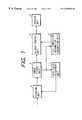
- FIG. 7 is a view showing distance measurement areas on an image pickup surface
- FIG. 8 is a graph showing a change in focus evaluation value depending on the position of a focus lens in units of distance measurement areas
- FIG. 9 is a flow chart showing the processing sequence of auto focus adjustment (AF) and finder display operations.
- FIG. 10 is a block diagram showing another embodiment of the present invention.
- FIG. 1 is a block diagram showing the principal functions of the electronic camera of this embodiment.
- the electronic camera of this embodiment comprises a focusing unit a, an image pickup unit b, an auto focus adjustment unit c, a display control unit d, a display unit e, and a tilt correction information generation unit f.
- the image pickup unit b has an image pickup element (see FIGS. 2A and 2B) for converting light L reflected by an object into an electrical signal, and outputting the electrical signal.
- the image pickup element is disposed on an image pickup surface on which the light L reflected by the object is focused.
- the focusing unit a focuses the light L reflected by the object on the image pickup surface of the image pickup element arranged in the image pickup unit b, and is constituted by various optical lenses.
- the auto focus adjustment unit c drives the focusing unit a, and performs adjustment to attain an in-focus state of an object image formed on the image pickup surface of the image pickup element of the image pickup unit b.
- a portion of the object image formed on the image pickup surface is subjected to divisional distance measurement operations.
- the display control unit d displays a plurality of pieces of distance measurement information obtained by the divisional distance measurement operations of the auto focus adjustment unit c on the display surface of the display unit e.
- the tilt correction information generation unit f generates tilt correction information for setting the image pickup surface of the camera to be parallel to a planar object on the basis of the divisional distance measurement results from the image pickup unit b, and displays the information on the display surface of the display unit e.
- a digital electronic camera 100 uses a memory card 801 as its recording medium.
- the digital electronic camera 100 comprises a photographing lens 1 , a shutter 2 also used as an iris, which shutter has both iris and shutter functions, an electronic flash 3 , an electronic viewfinder (EVF) 4 used for monitoring an image to be photographed and for displaying various kinds of information for helping operations, and the states of the camera, and an operation unit 5 consisting of various switches used for externally controlling the digital electronic camera 100 of this embodiment.
- the camera 100 also comprises an image pickup element 6 for converting an object image, which is obtained by focusing light reflected by an object by the photographing lens 1 , into an electrical signal, and a timing signal generation circuit (TG) 7 for generating a timing signal required for operating the image pickup element.
- an image pickup element 6 for converting an object image, which is obtained by focusing light reflected by an object by the photographing lens 1 , into an electrical signal
- a timing signal generation circuit (TG) 7 for generating a timing signal required for operating the image pickup element.
- the camera 100 further comprises an image pickup element drive circuit 8 for amplifying a signal from the timing signal generation circuit to a level high enough to drive the image pickup element and generating various drive pulses, and a preprocessing circuit 9 including a CDS (correlation double sampling) circuit for removing noise output from the image pickup element 6 and a nonlinear amplifier circuit required before A/D conversion.
- an image pickup element drive circuit 8 for amplifying a signal from the timing signal generation circuit to a level high enough to drive the image pickup element and generating various drive pulses
- a preprocessing circuit 9 including a CDS (correlation double sampling) circuit for removing noise output from the image pickup element 6 and a nonlinear amplifier circuit required before A/D conversion.
- CDS correlation double sampling
- the camera 100 comprises an A/D converter 10 and a focus detection circuit 11 .
- the focus detection circuit 11 of this embodiment has five distance measurement areas A 0 , A 1 , A 2 , A 3 , and A 4 shown in FIG. 7 in its image pickup surface, detects the sharpness of an image in each area on the basis of the rise state of the edge, i.e., sharpness, of an image pickup signal, and generates a focus evaluation value of each area by signal processing of the sharpness.
- the camera 100 comprises a buffer memory 12 and a microprocessor 13 .
- the microprocessor 13 is arranged for controlling the respective signal processing units, the mechanical portion of the camera, and the operation unit.
- the camera 100 further comprises an EVF drive circuit 14 , a motor 15 as a focus lens drive unit, a drive unit 16 of the shutter also used as an iris, and an electronic flash circuit 17 .
- the camera 100 also comprises a memory controller 802 for controlling the buffer memory 12 for temporarily storing a picked-up image, a digital signal processing circuit 803 for converting the output from the image pickup element 6 into a recording format suitable for the memory card 801 , and a memory card I/F 804 for connecting the digital electronic camera 100 and the memory card 801 .
- a memory controller 802 for controlling the buffer memory 12 for temporarily storing a picked-up image
- a digital signal processing circuit 803 for converting the output from the image pickup element 6 into a recording format suitable for the memory card 801
- a memory card I/F 804 for connecting the digital electronic camera 100 and the memory card 801 .
- the operation of the electronic camera of this embodiment will be described below based on the above-mentioned arrangement.
- the camera starts a photographing preparation operation.
- light reflected by an object becomes incident on the image pickup element 6 via the photographing lens 1 and the shutter 2 also used as an iris, and forms an object image on the image pickup surface of the image pickup element 6 .
- the shutter 2 also used as an iris performs an iris operation under the control of the drive unit 16 of the shutter also used as an iris, and serves as an iris for controlling the amount of light incident on the image pickup element 6 .
- the image pickup element 6 is operated by a drive signal generated by the image pickup element drive circuit 8 on the basis of the output from the timing signal generation circuit 7 . Note that the operation of the timing signal generation circuit 7 is controlled by the microprocessor 13 .
- the output from the image pickup element 6 driven as described above is input to the preprocessing circuit 9 arranged at the output side of the element 6 .
- the preprocessing circuit 9 performs CDS processing for removing low-frequency noise included in the output from the image pickup element 6 , and processing for nonlinearly converting the image pickup output so as to effectively use the dynamic range of the A/D converter 10 .
- the brightness of the object is measured based on the output from the image pickup element 6 , and the microprocessor 13 calculates the iris value and shutter speed, for main exposure, of the shutter 2 also used as an iris.
- the iris diameter of the drive unit 16 of the shutter also used as an iris is feedback-controlled to the microprocessor 13 so as to perform an auto focus adjustment operation.
- the electronic flash circuit 17 starts a charging operation for preparing for light emission.
- the focus detection circuit 11 , the microprocessor 13 , and the focus lens drive unit (motor) 15 perform so-called hill-climb type auto focus adjustment for driving the focus lens to maximize the focus evaluation value on the basis of the image pickup signal preprocessed by the preprocessing circuit 9 .
- the same image pickup signal is supplied to the EVF 4 via the EVF drive circuit 14 , and is displayed on the EVF 4 .
- the photographer can monitor the object image.
- photographing conditions calculated by the microprocessor 13 and tilt information are supplied to the EVF 4 via the EVF drive circuit 14 and are displayed on the EVF 4 .
- the photographer can know the photographing state of the camera.
- the electronic camera When the photographer depresses the release button of the operation unit 5 to its full stroke position, the electronic camera starts a photographing operation.
- the iris diameter of the shutter 2 also used as an iris is controlled by the drive unit 16 of the shutter also used as an iris to a size based on the calculated control value. With this control, the amount of light incident on the image pickup element 6 is appropriately limited.
- the image pickup element 6 comprises an interlace read type CCD
- incident light after the photographing operation can be prevented from adversely influencing the signal charge during charge transfer, by closing the shutter.
- the photographing operation is performed by controlling the electronic flash 3 to emit light by the electronic flash circuit 17 .
- the preprocessed image pickup signal output obtained by the main exposure is supplied to the A/D converter 10 , and is converted into a digital signal.
- the digital signal is input to the memory controller 802 .
- the memory controller 802 temporarily stores the digital image pickup signal in the buffer memory 12 under the control of the microprocessor, and then reads out the stored signal in a predetermined order determined by, e.g., the pixel layout of color filters of the image pickup element 6 .
- the readout digital signal is converted into a signal in a predetermined format by the digital signal processing circuit 803 , and the converted signal is recorded on the memory card 801 via the memory card I/F 804 .
- FIGS. 3A and 3B are optical path diagrams showing the positional relationship among the object, the lens, and the image pickup element 6 (CCD), and the optical path.
- the focusing state changes depending on the position of a picked-up image. More specifically, points P 1 , P 2 , and P 3 on the object will be examined below.
- the point P 2 on the optical axis is an in-focus point
- the point P 1 above the optical axis in FIG. 3A is a point on the front focus side of the focal plane
- the point P 3 is a point on the rear focus side of the focal plane.
- the locus of the sharpness evaluation value has a waveform, as shown in FIG. 8 .
- a solid curve represents the locus of the focus evaluation value on the central distance measurement area near the point P 2 on the focal plane.
- an alternate long and short dashed curve represents the locus of the focus evaluation value on an area where the point P 1 on the front focus side of the focal plane is present
- a broken curve represents the locus of the focus evaluation value on an area where the point P 3 on the rear focus side of the focal plane is present.
- focus lens positions X 1 , X 2 , and X 3 corresponding to the vertices of the three loci can be set to be equal to each other.
- the electronic camera main body including the lens and the CCD can be tilted so that a portion, where the point P 1 on the object is present, above the optical axis, i.e., a portion of the area in the front focus state is moved toward the nearest side, and a portion, where the point P 3 on the object, below the optical axis, i.e., a portion of the area in the rear focus state is moved toward the infinity side. If the position of the electronic camera is not moved, framing must be performed again since objects in other directions may be photographed.
- FIG. 4A shows an example of all the display marks in the finder. As shown in FIG. 4A, arrows and dots can be displayed at positions corresponding to the respective distance measurement areas A 1 to A 4 shown in FIG. 7, and in an in-focus state, only a dot is turned on.
- the length of each arrow is divided into three steps.
- the fourth distance measurement area A 4 located at the lower right position will be taken as an example.
- a black arrow pointing in the lower right direction is turned on.
- a lighter arrow pointing in the upper left direction is turned on.
- the length of the arrow can express the degree of an out-of-focus state in three steps.
- the displayed contents are determined based on the deviation amounts between peak focus lens positions Xa 1 to Xa 4 and the stop position.
- the number of divisions of the length of the arrow is not limited to three.
- a different number of divisions of the length of the arrow may be used or the length of the arrow may be continuously changed.
- FIG. 5 shows the display state corresponding to the state shown in FIG. 3 A.
- the lens and the image pickup surface of the CCD are not tilted relative to the object surface in a direction perpendicular to the plane of the drawing of FIG. 3A, two positions, i.e., the upper left position (first distance measurement area A 1 ) in the direction of the point P 1 and the upper right position (second distance measurement area A 2 ) indicate the front focus state.
- framing can be corrected by moving the camera so that the object roughly moves in a direction as the sum of the vectors of the arrows.
- some key-shaped line marks may be displayed on the areas of the four corners, and display patterns ( 1 ) to ( 4 ) may be repetitively displayed, as shown in FIG. 6 B.
- the degree of an out-of-focus state can be expressed by changing the repetition speed of the display patterns in correspondence with the degree of the out-of-focus state.
- Step S 1 When the release button is depressed to its half stroke position, auto focus adjustment (AF) is started.
- Step S 2 The focus lens drive unit 15 moves the focal point of the photographing lens, and the focus evaluation value on the central distance measurement area A 0 , which value is generated by the focus detection circuit 11 , is monitored, thus attaining hill-climb type focus adjustment.
- Step S 3 At this time, the focus detection circuit 11 also generates the focus evaluation values on the first to fourth distance measurement areas A 1 to A 4 , monitors these values, and stores peak values Ea 1 to Ea 4 on the distance measurement areas A 1 to A 4 and corresponding focus lens positions Xa 1 to Xa 4 .
- Step S 4 The focus lens is stopped at the in-focus position on the distance measurement area A 0 .
- Step S 5 It is checked if all the distance measurement areas A 1 to A 4 are in an in-focus state. This decision step is attained by comparing the stop position of the focus lens with the peak positions Xa 1 to Xa 4 of the respective areas by the microprocessor 13 . More specifically, if the comparison result indicates an identical position, it is determined that the area of interest is in an in-focus state; otherwise, it is checked if the in-focus position is present on the front or rear focus side, and the defocus amount of each distance measurement area is determined by the difference between the two positions.
- the focus evaluation values on the distance measurement areas A 1 to A 4 upon stopping the focus lens are compared with the stored peak values Ea 1 to Ea 4 of these areas, and if the difference between the two values for each area is equal to or smaller than a predetermined threshold value, it is determined that the focus evaluation value of the area of interest falls within the object depth. Thus, in this case, it may be determined that the area of interest is in an in-focus state.
- the microprocessor 13 determines the display contents based on the comparison results, and supplies a display instruction signal to the EVF drive circuit 14 .
- step S 6 If all the distance measurement areas A 1 to A 4 are in an in-focus state, the flow advances to step S 6 ; otherwise, the flow advances to step S 8 .
- Step S 6 A message indicating that an in-focus state is attained is displayed, and thereafter, the flow advances to step S 8 to set a standby state in which the camera waits for a main exposure operation.
- Step S 7 The out-of-focus amounts and directions of the respective areas are displayed on the EVF 4 .
- the photographer changes the direction of the electronic camera in accordance with the displayed information, thus performing framing again. Thereafter, the flow returns to step S 2 , and the-above-mentioned processing is repeated until the message indicating that an in-focus state is attained is displayed in step S 6 .
- the divisional distance measurement AF is performed using five areas. However, since three points can designate one plane, the number of divisions can be at least three.
- the distance measurement can be performed at four corners and the central portion, and distance measurement information can be displayed at the four corners. For this reason, the photographer can easily understand the tilt correction direction independently of the tilt direction of the camera, i.e., vertical, horizontal, and oblique directions.
- the electronic camera of this embodiment since the electronic camera of this embodiment generates information indicating whether or not the central portion and peripheral portions are present at an equal distance from an object on the basis of distance measurement information obtained at a large number of points by the divisional distance measurement operations of an object image, and displays the generated information on the display unit, a photographer can accurately perform a photographing operation of, e.g., an original while holding the camera with his or her hands, without fixing the camera using a stand or base, and a photographing failure when the entire object image is not in an in-focus state can be prevented.
- the above-mentioned photographing operation can be performed without arranging any tilt mechanism, the arrangement of the electronic camera which can obtain photographing data that allows easy character recognition can be simplified, thus reducing the manufacturing cost.
- the tilt correction information for correcting the tilt state of the camera is displayed on the display surface of the display unit, the photographer can easily understand the tilt correction direction, and tilt adjustment can be attained even at an image quality as low as that of the EVF.
- FIG. 10 shows another embodiment of the present invention.
- the tilt state of the camera is displayed by displaying focusing states on respective portions of the image pickup surface on the monitor display.
- the tilt state is automatically adjusted.
- a photographing lens 101 allows focus adjustment and tilt adjustment.
- An object image formed via the photographing lens 101 is photoelectrically converted into an image pickup signal by an image pickup element in an image pickup unit 102 , and is subjected to predetermined camera signal processing. Thereafter, the processed signal is output, and is displayed on a monitor display 104 via a display control unit 103 .
- the image pickup signal output from the image pickup element of the image pickup unit 102 is also supplied to an auto focus adjustment circuit 105 , and focus evaluation values such as edge components of an image are extracted on a plurality of areas in the image pickup surface, as described above, thus performing focus detection.
- the auto focus adjustment circuit detects a change in focusing state of each area by reciprocally displacing the lens by a predetermined small distance along the optical axis, thus detecting the in-focus, front focus, and rear focus areas.
- the detection result is supplied to a tilt correction information generation circuit 106 , and the tilt state of the lens relative to an object (e.g., an original) is discriminated on the basis of the front focus information, in-focus information, and rear focus information of the respective areas.
- the tilt state information is supplied to the display control unit 103 , and is displayed on the monitor display 104 such as an electronic viewfinder together with an image as in the above-mentioned embodiment.
- the tilt correction information generated by the tilt correction information generation circuit 106 is supplied to a tilt drive circuit 108 .
- the circuit 108 drives a tilt adjustment motor of the lens 101 to correct the tilt state of the lens 101 .
- the tilt state of the lens 101 relative to the object is detected and displayed, and the tilt state of the lens can be corrected by automatic adjustment.
- a photographing failure of, e.g., an original image when an out-of-focus state locally occurs due to a tilt state of the lens relative to the original can be prevented.
Abstract
An electronic camera having a lens, an image pickup element for converting an object image formed on an image pickup surface into an electrical signal, a focus detection means for dividing the object image formed on the image pickup surface into a plurality of areas, and performing focus detection on the respective areas, a drive circuit for adjusting the lens on the basis of an output from the focus detection means, and a display circuit for displaying simultaneously focus detection information of the plurality of areas of the focus detection circuit on its display screen.
Description
1. Field of the Invention
The present invention relates to an electronic camera and, more particularly, to a high-image quality electronic camera which allows character recognition and the like.
2. Related Background Art
Conventionally, in order to input characters written on an original or the like into a computer, for example, an image scanner using a linear photoelectric conversion element is used for inputting the character images.
In this case, in the input operation, the original written with the characters is horizontally held by being pressed against the surface of a transparent member such as a glass plate.
Image signals obtained in this manner are subjected to character recognition processing using a hardware arrangement such as a computer having a character recognition processing function or a software program having a character recognition processing function.
Also, a method in which a video signal obtained from a camera is input to the above-mentioned computer having the character recognition processing function and is subjected to character recognition processing has been proposed.
When the character recognition processing is performed based on a video signal obtained from the camera, as described above, if an object to be photographed is not parallel to an image pickup surface, an in-focus state cannot be attained on the entire area of the object to be photographed.
In order to solve such a problem, a method of adjusting an optical system using a tilt mechanism such as a tilt & shift mechanism to attain an in-focus state on the entire area of the object to be photographed even if the object to be photographed is not parallel to the image pickup surface has been proposed.
However, when an object to be photographed written with characters is to be photographed using a camera, it is difficult to attain an in-focus state on the entire surface of the object to be photographed. For this reason, the photographing operation is performed using a base, stand or the like for fixing the object to be parallel to the image pickup surface. This method is inconvenient since it requires a cumbersome operation of setting the base or stand for fixing the object and the camera, and it renders the photographing apparatus bulky.
With the above-mentioned method, an object to be subjected to the photographing operation for performing character recognition is limited to one that can be placed under the base, such as a paper sheet. Therefore, it is difficult to photograph an image of a signboard such as a directional sign, road sign, or the like, a large object or an immovable object such as a plate attached to an industrial product, or a three-dimensional object.
As described above, an in-focus state can be attained on the entire object or an image distortion can be eliminated using an optical system having a tilt mechanism such as a tilt & shift mechanism even when the image pickup surface is not perpendicular to the object. However, the tilt mechanism cannot be easily operated since it requires skills in adjustment.
An electronic camera which automates adjustment requiring skills has also been proposed. However, such a camera has a high cost since it requires a complicated mechanism and a complicated control.
The present invention has been made in consideration of the above situation, and has as its first object to provide an electronic camera which can realize a high-image quality photographing operation.
It is the second object of the present invention to provide an inexpensive electronic camera which can easily attain character recognition.
It is the third object of the present invention to provide an electronic camera which can realize accurate focus adjustment on the entire image pickup surface.
In order to achieve the above objects, according to a preferred embodiment of the present invention, there is disclosed an electronic camera comprising image pickup means for converting an object image formed on an image pickup surface into an electrical signal, focusing means for forming the object image on the image pickup surface, focus detection means for dividing the object image formed on the image pickup surface into a plurality of portions, and performing focus detection for the plurality of portions, focus adjustment means for adjusting the position of the focusing means on the basis of outputs from the focus detection means, and display means for displaying focus detection information of the plurality of portions detected by the focus detection means.
According to a preferred embodiment of the present invention, there is disclosed an electronic camera which further comprises tilt correction information generation means for generating tilt correction information used for setting the image pickup surface of the camera to be parallel to a planar object on the basis of results obtained by the divisional distance measurement operations of the focus detection means, and displays the tilt correction information on the display surface of the display means.
According to a preferred embodiment of the present invention, distance measurement information at each of a large number of points obtained by the divisional distance measurement operations of the focus detection means can be displayed in a finder. With this information, a user can confirm, during a photographing operation, whether or not an in-focus state is attained on the entire object with respect to the image pickup surface. Thus, a photographing failure when an in-focus state is not attained on the entire object can be prevented.
It is still another object of the present invention to provide an electronic camera which can notify a photographer of the current tilt direction of the camera during a photographing operation so as to allow the photographer to perform easy tilt adjustment, and can easily set an in-focus state on the entire object.
Other objects and features of the present invention will become apparent from the following specification and the accompanying drawings.
FIG. 1 is a block diagram showing the functional arrangement of an electronic camera according to the present invention;
FIG. 2 which is composed of FIGS. 2A and 2B is a block diagram showing the arrangement of an electronic camera according to an embodiment of the present invention;
FIGS. 3A and 3B are optical path diagrams of the electronic camera in the embodiment shown in FIGS. 2A and 2B;
FIG. 4A is a view showing all the display marks in a finder in the embodiment shown in FIGS. 2A and 2B, and
FIG. 4B is a view showing an example of a turn-on method of the display marks, whose patterns change depending on the focusing state, in the finder in the embodiment shown in FIGS. 2A and 2B;
FIG. 5 is a view showing an example of the turn-on method of the display marks in the finder in the embodiment shown in FIGS. 2A and 2B;
FIG. 6A is a view showing another example of all the display marks in the finder in the embodiment shown in FIGS. 2A and 2B, and
FIG. 6B is a view showing another example of the turn-on method of the display marks, whose patterns change depending on the focusing state, in the finder in the embodiment shown in FIGS. 2A and 2B;
FIG. 7 is a view showing distance measurement areas on an image pickup surface;
FIG. 8 is a graph showing a change in focus evaluation value depending on the position of a focus lens in units of distance measurement areas;
FIG. 9 is a flow chart showing the processing sequence of auto focus adjustment (AF) and finder display operations; and
FIG. 10 is a block diagram showing another embodiment of the present invention.
An embodiment of an electronic camera according to the present invention will be described below with reference to the accompanying drawings.
FIG. 1 is a block diagram showing the principal functions of the electronic camera of this embodiment. As shown in FIG. 1, the electronic camera of this embodiment comprises a focusing unit a, an image pickup unit b, an auto focus adjustment unit c, a display control unit d, a display unit e, and a tilt correction information generation unit f.
The image pickup unit b has an image pickup element (see FIGS. 2A and 2B) for converting light L reflected by an object into an electrical signal, and outputting the electrical signal. The image pickup element is disposed on an image pickup surface on which the light L reflected by the object is focused.
The focusing unit a focuses the light L reflected by the object on the image pickup surface of the image pickup element arranged in the image pickup unit b, and is constituted by various optical lenses.
The auto focus adjustment unit c drives the focusing unit a, and performs adjustment to attain an in-focus state of an object image formed on the image pickup surface of the image pickup element of the image pickup unit b. In this embodiment, a portion of the object image formed on the image pickup surface is subjected to divisional distance measurement operations.
The display control unit d displays a plurality of pieces of distance measurement information obtained by the divisional distance measurement operations of the auto focus adjustment unit c on the display surface of the display unit e.
The tilt correction information generation unit f generates tilt correction information for setting the image pickup surface of the camera to be parallel to a planar object on the basis of the divisional distance measurement results from the image pickup unit b, and displays the information on the display surface of the display unit e.
The arrangement of the electronic camera of this embodiment will be described in detail below with reference to the block diagram in FIGS. 2A and 2B.
Referring to FIGS. 2A and 2B, a digital electronic camera 100 uses a memory card 801 as its recording medium.
The digital electronic camera 100 comprises a photographing lens 1, a shutter 2 also used as an iris, which shutter has both iris and shutter functions, an electronic flash 3, an electronic viewfinder (EVF) 4 used for monitoring an image to be photographed and for displaying various kinds of information for helping operations, and the states of the camera, and an operation unit 5 consisting of various switches used for externally controlling the digital electronic camera 100 of this embodiment.
The camera 100 also comprises an image pickup element 6 for converting an object image, which is obtained by focusing light reflected by an object by the photographing lens 1, into an electrical signal, and a timing signal generation circuit (TG) 7 for generating a timing signal required for operating the image pickup element.
The camera 100 further comprises an image pickup element drive circuit 8 for amplifying a signal from the timing signal generation circuit to a level high enough to drive the image pickup element and generating various drive pulses, and a preprocessing circuit 9 including a CDS (correlation double sampling) circuit for removing noise output from the image pickup element 6 and a nonlinear amplifier circuit required before A/D conversion.
Moreover, the camera 100 comprises an A/D converter 10 and a focus detection circuit 11. The focus detection circuit 11 of this embodiment has five distance measurement areas A0, A1, A2, A3, and A4 shown in FIG. 7 in its image pickup surface, detects the sharpness of an image in each area on the basis of the rise state of the edge, i.e., sharpness, of an image pickup signal, and generates a focus evaluation value of each area by signal processing of the sharpness.
In addition, the camera 100 comprises a buffer memory 12 and a microprocessor 13. The microprocessor 13 is arranged for controlling the respective signal processing units, the mechanical portion of the camera, and the operation unit. The camera 100 further comprises an EVF drive circuit 14, a motor 15 as a focus lens drive unit, a drive unit 16 of the shutter also used as an iris, and an electronic flash circuit 17.
The camera 100 also comprises a memory controller 802 for controlling the buffer memory 12 for temporarily storing a picked-up image, a digital signal processing circuit 803 for converting the output from the image pickup element 6 into a recording format suitable for the memory card 801, and a memory card I/F 804 for connecting the digital electronic camera 100 and the memory card 801.
The operation of the electronic camera of this embodiment will be described below based on the above-mentioned arrangement. When a photographer depresses the release button of the operation unit 5 to its half stroke position, the camera starts a photographing preparation operation. With this operation, light reflected by an object becomes incident on the image pickup element 6 via the photographing lens 1 and the shutter 2 also used as an iris, and forms an object image on the image pickup surface of the image pickup element 6.
At this time, the shutter 2 also used as an iris performs an iris operation under the control of the drive unit 16 of the shutter also used as an iris, and serves as an iris for controlling the amount of light incident on the image pickup element 6.
The image pickup element 6 is operated by a drive signal generated by the image pickup element drive circuit 8 on the basis of the output from the timing signal generation circuit 7. Note that the operation of the timing signal generation circuit 7 is controlled by the microprocessor 13.
The output from the image pickup element 6 driven as described above is input to the preprocessing circuit 9 arranged at the output side of the element 6.
The preprocessing circuit 9 performs CDS processing for removing low-frequency noise included in the output from the image pickup element 6, and processing for nonlinearly converting the image pickup output so as to effectively use the dynamic range of the A/D converter 10.
The brightness of the object is measured based on the output from the image pickup element 6, and the microprocessor 13 calculates the iris value and shutter speed, for main exposure, of the shutter 2 also used as an iris. During the photographing preparation operation, the iris diameter of the drive unit 16 of the shutter also used as an iris is feedback-controlled to the microprocessor 13 so as to perform an auto focus adjustment operation.
If it is determined that the brightness is insufficient, the electronic flash circuit 17 starts a charging operation for preparing for light emission.
Furthermore, the focus detection circuit 11, the microprocessor 13, and the focus lens drive unit (motor) 15 perform so-called hill-climb type auto focus adjustment for driving the focus lens to maximize the focus evaluation value on the basis of the image pickup signal preprocessed by the preprocessing circuit 9.
The same image pickup signal is supplied to the EVF 4 via the EVF drive circuit 14, and is displayed on the EVF 4. Thus, the photographer can monitor the object image.
Simultaneously with the monitoring operation of the object image, photographing conditions calculated by the microprocessor 13 and tilt information (to be described later) are supplied to the EVF 4 via the EVF drive circuit 14 and are displayed on the EVF 4. With these pieces of information, the photographer can know the photographing state of the camera.
When the photographer depresses the release button of the operation unit 5 to its full stroke position, the electronic camera starts a photographing operation. In this case, the iris diameter of the shutter 2 also used as an iris is controlled by the drive unit 16 of the shutter also used as an iris to a size based on the calculated control value. With this control, the amount of light incident on the image pickup element 6 is appropriately limited.
In particular, when the image pickup element 6 comprises an interlace read type CCD, incident light after the photographing operation can be prevented from adversely influencing the signal charge during charge transfer, by closing the shutter.
Depending on the output from a photometry circuit, the photographing operation is performed by controlling the electronic flash 3 to emit light by the electronic flash circuit 17.
In this manner, the preprocessed image pickup signal output obtained by the main exposure is supplied to the A/D converter 10, and is converted into a digital signal. The digital signal is input to the memory controller 802. The memory controller 802 temporarily stores the digital image pickup signal in the buffer memory 12 under the control of the microprocessor, and then reads out the stored signal in a predetermined order determined by, e.g., the pixel layout of color filters of the image pickup element 6.
The readout digital signal is converted into a signal in a predetermined format by the digital signal processing circuit 803, and the converted signal is recorded on the memory card 801 via the memory card I/F 804.
Generation of tilt information and the auto focus adjustment operation in the electronic camera of this embodiment will be described below.
FIGS. 3A and 3B are optical path diagrams showing the positional relationship among the object, the lens, and the image pickup element 6 (CCD), and the optical path.
As shown in FIG. 3A, when the image pickup surface is tilted relative to the object, the focusing state changes depending on the position of a picked-up image. More specifically, points P1, P2, and P3 on the object will be examined below. In the case of FIG. 3A, the point P2 on the optical axis is an in-focus point, the point P1 above the optical axis in FIG. 3A is a point on the front focus side of the focal plane, and the point P3 is a point on the rear focus side of the focal plane.
At this time, when the above-mentioned hill-climb type auto focus adjustment based on sharpness evaluation of the image is performed by driving the focus lens, the locus of the sharpness evaluation value has a waveform, as shown in FIG. 8.
Referring to FIG. 8, a solid curve represents the locus of the focus evaluation value on the central distance measurement area near the point P2 on the focal plane. On the other hand, an alternate long and short dashed curve represents the locus of the focus evaluation value on an area where the point P1 on the front focus side of the focal plane is present, and a broken curve represents the locus of the focus evaluation value on an area where the point P3 on the rear focus side of the focal plane is present.
Therefore, in order to attain an in-focus state of the entire object, the focal plane parallel to the lens and the image pickup surface of the electronic camera need only overlap the object surface. For this purpose, focus lens positions X1, X2, and X3 corresponding to the vertices of the three loci can be set to be equal to each other.
As shown in FIG. 3B, the electronic camera main body including the lens and the CCD can be tilted so that a portion, where the point P1 on the object is present, above the optical axis, i.e., a portion of the area in the front focus state is moved toward the nearest side, and a portion, where the point P3 on the object, below the optical axis, i.e., a portion of the area in the rear focus state is moved toward the infinity side. If the position of the electronic camera is not moved, framing must be performed again since objects in other directions may be photographed.
FIG. 4A shows an example of all the display marks in the finder. As shown in FIG. 4A, arrows and dots can be displayed at positions corresponding to the respective distance measurement areas A1 to A4 shown in FIG. 7, and in an in-focus state, only a dot is turned on.
In this embodiment, the length of each arrow is divided into three steps. The fourth distance measurement area A4 located at the lower right position will be taken as an example. As shown in FIG. 4B, in a front focus state, a black arrow pointing in the lower right direction is turned on. In a rear focus state, a lighter arrow pointing in the upper left direction is turned on. The length of the arrow can express the degree of an out-of-focus state in three steps.
The displayed contents are determined based on the deviation amounts between peak focus lens positions Xa1 to Xa4 and the stop position. Note that the number of divisions of the length of the arrow is not limited to three. For example, a different number of divisions of the length of the arrow may be used or the length of the arrow may be continuously changed.
FIG. 5 shows the display state corresponding to the state shown in FIG. 3A. In FIG. 3A, since the lens and the image pickup surface of the CCD are not tilted relative to the object surface in a direction perpendicular to the plane of the drawing of FIG. 3A, two positions, i.e., the upper left position (first distance measurement area A1) in the direction of the point P1 and the upper right position (second distance measurement area A2) indicate the front focus state.
On the other hand, two positions, i.e., the lower left position (third distance measurement area A3) in the direction of the point P3 and the lower right position (fourth distance measurement area A4) indicate the rear focus state. For this reason, as shown in FIG. 5, black arrows are turned on at the upper right and left positions and lighter arrows are turned on at the lower right and left positions.
Note that framing can be corrected by moving the camera so that the object roughly moves in a direction as the sum of the vectors of the arrows.
As for the display method, as shown in FIGS. 6A and 6B, some key-shaped line marks may be displayed on the areas of the four corners, and display patterns (1) to (4) may be repetitively displayed, as shown in FIG. 6B. In this case, the degree of an out-of-focus state can be expressed by changing the repetition speed of the display patterns in correspondence with the degree of the out-of-focus state.
The above-mentioned operation will be described below with reference to the flow chart in FIG. 9.
Step S1: When the release button is depressed to its half stroke position, auto focus adjustment (AF) is started.
Step S2: The focus lens drive unit 15 moves the focal point of the photographing lens, and the focus evaluation value on the central distance measurement area A0, which value is generated by the focus detection circuit 11, is monitored, thus attaining hill-climb type focus adjustment.
Step S3: At this time, the focus detection circuit 11 also generates the focus evaluation values on the first to fourth distance measurement areas A1 to A4, monitors these values, and stores peak values Ea1 to Ea4 on the distance measurement areas A1 to A4 and corresponding focus lens positions Xa1 to Xa4.
Step S4: The focus lens is stopped at the in-focus position on the distance measurement area A0.
Step S5: It is checked if all the distance measurement areas A1 to A4 are in an in-focus state. This decision step is attained by comparing the stop position of the focus lens with the peak positions Xa1 to Xa4 of the respective areas by the microprocessor 13. More specifically, if the comparison result indicates an identical position, it is determined that the area of interest is in an in-focus state; otherwise, it is checked if the in-focus position is present on the front or rear focus side, and the defocus amount of each distance measurement area is determined by the difference between the two positions.
Alternatively, the focus evaluation values on the distance measurement areas A1 to A4 upon stopping the focus lens are compared with the stored peak values Ea1 to Ea4 of these areas, and if the difference between the two values for each area is equal to or smaller than a predetermined threshold value, it is determined that the focus evaluation value of the area of interest falls within the object depth. Thus, in this case, it may be determined that the area of interest is in an in-focus state.
The microprocessor 13 determines the display contents based on the comparison results, and supplies a display instruction signal to the EVF drive circuit 14.
If all the distance measurement areas A1 to A4 are in an in-focus state, the flow advances to step S6; otherwise, the flow advances to step S8.
Step S6: A message indicating that an in-focus state is attained is displayed, and thereafter, the flow advances to step S8 to set a standby state in which the camera waits for a main exposure operation.
Step S7: The out-of-focus amounts and directions of the respective areas are displayed on the EVF 4. The photographer changes the direction of the electronic camera in accordance with the displayed information, thus performing framing again. Thereafter, the flow returns to step S2, and the-above-mentioned processing is repeated until the message indicating that an in-focus state is attained is displayed in step S6.
In this embodiment, the divisional distance measurement AF is performed using five areas. However, since three points can designate one plane, the number of divisions can be at least three.
When five areas are used, the distance measurement can be performed at four corners and the central portion, and distance measurement information can be displayed at the four corners. For this reason, the photographer can easily understand the tilt correction direction independently of the tilt direction of the camera, i.e., vertical, horizontal, and oblique directions.
As described above, since the electronic camera of this embodiment generates information indicating whether or not the central portion and peripheral portions are present at an equal distance from an object on the basis of distance measurement information obtained at a large number of points by the divisional distance measurement operations of an object image, and displays the generated information on the display unit, a photographer can accurately perform a photographing operation of, e.g., an original while holding the camera with his or her hands, without fixing the camera using a stand or base, and a photographing failure when the entire object image is not in an in-focus state can be prevented. In addition, since the above-mentioned photographing operation can be performed without arranging any tilt mechanism, the arrangement of the electronic camera which can obtain photographing data that allows easy character recognition can be simplified, thus reducing the manufacturing cost.
Since the tilt correction information for correcting the tilt state of the camera is displayed on the display surface of the display unit, the photographer can easily understand the tilt correction direction, and tilt adjustment can be attained even at an image quality as low as that of the EVF.
FIG. 10 shows another embodiment of the present invention. In the above-mentioned embodiment, the tilt state of the camera is displayed by displaying focusing states on respective portions of the image pickup surface on the monitor display. However, in this embodiment, the tilt state is automatically adjusted.
Referring to FIG. 10, a photographing lens 101 allows focus adjustment and tilt adjustment. An object image formed via the photographing lens 101 is photoelectrically converted into an image pickup signal by an image pickup element in an image pickup unit 102, and is subjected to predetermined camera signal processing. Thereafter, the processed signal is output, and is displayed on a monitor display 104 via a display control unit 103.
On the other hand, the image pickup signal output from the image pickup element of the image pickup unit 102 is also supplied to an auto focus adjustment circuit 105, and focus evaluation values such as edge components of an image are extracted on a plurality of areas in the image pickup surface, as described above, thus performing focus detection.
With this operation, the focusing states on the respective areas in the image pickup surface are discriminated. The auto focus adjustment circuit detects a change in focusing state of each area by reciprocally displacing the lens by a predetermined small distance along the optical axis, thus detecting the in-focus, front focus, and rear focus areas.
The detection result is supplied to a tilt correction information generation circuit 106, and the tilt state of the lens relative to an object (e.g., an original) is discriminated on the basis of the front focus information, in-focus information, and rear focus information of the respective areas. The tilt state information is supplied to the display control unit 103, and is displayed on the monitor display 104 such as an electronic viewfinder together with an image as in the above-mentioned embodiment.
The tilt correction information generated by the tilt correction information generation circuit 106 is supplied to a tilt drive circuit 108. The circuit 108 drives a tilt adjustment motor of the lens 101 to correct the tilt state of the lens 101.
With this operation, the tilt state of the lens 101 relative to the object is detected and displayed, and the tilt state of the lens can be corrected by automatic adjustment.
According to this embodiment, a photographing failure of, e.g., an original image when an out-of-focus state locally occurs due to a tilt state of the lens relative to the original can be prevented.
Claims (25)
1. An electronic camera comprising:
a photographing lens;
image pickup means for photoelectrically converting an object image formed on an image pickup plane by said photographing lens;
focus detection means for dividing the image pickup plane into a plurality of non-overlapping areas, and detecting a focusing state of each of the respective areas; and
display means for simultaneously displaying on a monitor a change of an out-of-focus direction of each of the plurality of non-overlapping areas in accordance with a detection result of said focus detection means, respectively.
2. A camera according to claim 1 , further comprising:
tilt correction information generation means for generating tilt correction information used for setting the image pickup plane of the camera to be parallel to a planar object on the basis of information of the detected focusing states of the respective areas.
3. A camera according to claim 1 , wherein the plurality of areas include a central portion of the image pickup plane and a plurality of areas around the central portion.
4. A camera according to claim 1 , wherein said display means comprises an electronic viewfinder.
5. An electronic camera comprising:
a photographing lens;
image pickup means for photoelectrically converting an object image formed on an image pickup plane by said photographing lens;
focus detection means for dividing the image pickup plane into a plurality of areas, and detecting focusing states on the respective areas;
tilt detection means for detecting a tilt of said photographing lens on the basis of information of the focusing states of the respective areas detected by said focus detection means; and
tilt correction means for correcting the tilt of said photographing lens on the basis of an output from said tilt detection means.
6. A camera according to claim 5 , wherein said tilt correction means comprises tilt correction information generation means for generating tilt correction information used for setting the image pickup plane of the camera to be parallel to a planar object, and correcting the tilt of said photographing lens on the basis of the tilt correction information.
7. A camera according to claim 5 , wherein the plurality of areas include a central portion of the image pickup plane and a plurality of areas around the central portion.
8. A camera according to claim 5 , wherein said display means comprises an electronic viewfinder.
9. A camera according to claim 5 , further comprising auto focus adjustment means for performing focus adjustment of said photographing lens on the basis of an output from said focus detection means.
10. An electronic camera comprising:
an optical system;
image pickup means for photoelectrically converting an object image formed on an image pickup plane by said optical system;
detection means for dividing the image pickup plane into a plurality of non-overlapping areas, and detecting an image sensing state of each of the respective areas; and
display means for simultaneously displaying on a monitor a change of an out-of-focus direction of each of the plurality of non-overlapping areas in accordance with a detection result of said detection means, respectively.
11. A camera according to claim 10 , further comprising:
tilt correction information generation means for generating tilt correction information used for setting the image pickup plane of the camera to be parallel with a planar object on the basis of information of the detected focusing states of the respective areas.
12. A camera according to claim 10 , wherein the plurality of areas include a central portion of the image pickup plane and a plurality of areas around the central portion.
13. An electronic camera comprising:
a photographing lens;
image pickup means for photoelectrically converting an object image formed on an image pickup plane by said photographing lens;
focus detection means for dividing the image pickup plane into a plurality of areas, and detecting focusing states on the respective areas;
display means for displaying the focusing states on the plurality of areas detected by said focus detection means; and
tilt correction information generation means for generating tilt correction information used for setting the image pickup surface of the camera to be parallel to a planar object on the basis of information of the detected focusing states of the respective areas.
14. A camera according to claim 13 , wherein the plurality of areas include a central portion of the image pickup plane and a plurality of areas around the central portion.
15. A camera according to claim 13 , wherein said display means comprises an electronic viewfinder.
16. An apparatus comprising:
a focus stated detection device that detects a focus state of each of a plurality of detection areas of an imaging surface of an image pickup device on which an image forming optical system forms an image; and
a display device that displays a change direction of an out-of-focus state in each of the plurality of detection areas in accordance with a detection result of said focus state detection device.
17. Apparatus according to claim 16 , wherein said apparatus includes a camera.
18. Apparatus according to claim 16 , wherein said apparatus includes an electronic image pickup camera.
19. Apparatus according to claim 16 , wherein said apparatus includes a focusing device.
20. An apparatus comprising:
a focus state detection device that detects a focus state of each of a plurality of detection areas of an imaging surface of an image pickup device on which an image forming optical system forms an image; and
an information forming device that forms tilt correction information of an optical axis of said image forming optical system in accordance with a detection result of said focus state detection device.
21. Apparatus according to claim 20 , further comprising a display device that performs a display corresponding to the tilt correction information formed by said information forming device.
22. Apparatus according to claim 21 , further comprising:
a driving device that drives said image forming optical system in accordance with the tilt correction information formed by said information forming device.
23. Apparatus according to claim 20 , wherein said apparatus includes a camera.
24. Apparatus according to claim 20 , wherein said apparatus includes an electronic image pickup camera.
25. Apparatus according to claim 20 , wherein said apparatus includes a focusing device.
Applications Claiming Priority (2)
| Application Number | Priority Date | Filing Date | Title |
|---|---|---|---|
| JP6328496A JPH08186757A (en) | 1994-12-28 | 1994-12-28 | Electronic camera |
| JP6-328496 | 1994-12-28 |
Publications (1)
| Publication Number | Publication Date |
|---|---|
| US6359650B1 true US6359650B1 (en) | 2002-03-19 |
Family
ID=18210936
Family Applications (1)
| Application Number | Title | Priority Date | Filing Date |
|---|---|---|---|
| US08/577,345 Expired - Lifetime US6359650B1 (en) | 1994-12-28 | 1995-12-22 | Electronic camera having a tilt detection function |
Country Status (2)
| Country | Link |
|---|---|
| US (1) | US6359650B1 (en) |
| JP (1) | JPH08186757A (en) |
Cited By (53)
| Publication number | Priority date | Publication date | Assignee | Title |
|---|---|---|---|---|
| US20010022626A1 (en) * | 2000-01-26 | 2001-09-20 | Nikon Corporation | Camera |
| US20020018139A1 (en) * | 2000-06-16 | 2002-02-14 | Hisayuki Yamagata | Device for detecting tilt angle of optical axis and image measuring apparatus equipped therewith |
| US20030016883A1 (en) * | 2001-07-20 | 2003-01-23 | Baron John M. | System and method for horizon correction within images |
| US20030117511A1 (en) * | 2001-12-21 | 2003-06-26 | Eastman Kodak Company | Method and camera system for blurring portions of a verification image to show out of focus areas in a captured archival image |
| US6606117B1 (en) * | 1997-09-15 | 2003-08-12 | Canon Kabushiki Kaisha | Content information gathering apparatus system and method |
| US6670991B1 (en) * | 1997-09-26 | 2003-12-30 | Canon Kabushiki Kaisha | Image sensing system, control method, and recording medium for controlling a camera apparatus utilizing a client device connected thereto |
| US20040141061A1 (en) * | 1997-07-12 | 2004-07-22 | Kia Silverbrook | Image sensing and printing device |
| US20040201770A1 (en) * | 2003-04-09 | 2004-10-14 | Fuji Photo Film Co., Ltd. | Pickup device for picking up image |
| US20040218086A1 (en) * | 2003-05-02 | 2004-11-04 | Voss James S. | System and method for providing camera focus feedback |
| US20040239630A1 (en) * | 2003-05-30 | 2004-12-02 | Ramakrishna Kakarala | Feedback to users of optical navigation devices on non-navigable surfaces |
| US20060044452A1 (en) * | 2002-10-24 | 2006-03-02 | Yoshio Hagino | Focus state display |
| US20060082657A1 (en) * | 2004-10-19 | 2006-04-20 | Raymond Meier | Digital camera improvements |
| US20060146174A1 (en) * | 2003-02-07 | 2006-07-06 | Yoshio Hagino | Focused state display device and focused state display method |
| US20070011023A1 (en) * | 1997-07-15 | 2007-01-11 | Silverbrook Research Pty Ltd | Apparatus for authenticating the validity of a device |
| US20070115363A1 (en) * | 2005-11-18 | 2007-05-24 | Fujifilm Corporation | Imaging device |
| US20080068433A1 (en) * | 1997-07-15 | 2008-03-20 | Silverbrook Research Pty Ltd | Print Medium Having A Ribbed Structure |
| US20080204562A1 (en) * | 1997-07-15 | 2008-08-28 | Silverbrook Research Pty Ltd | Camera system having serially connected camera devices to facilitate a cascade of imaging effects |
| US20080252754A1 (en) * | 1997-07-15 | 2008-10-16 | Silverbrook Research Pty Ltd | Card based image manipulation method with card skew correction |
| CN100456120C (en) * | 2005-09-08 | 2009-01-28 | 普立尔科技股份有限公司 | Focusing method for image pickup device |
| US20090052879A1 (en) * | 1997-07-15 | 2009-02-26 | Silverbrook Research Pty Ltd | Digital camera with ink reservoir and ink reservoir information integrated circuit |
| CN100465783C (en) * | 2005-10-09 | 2009-03-04 | 致伸科技股份有限公司 | Focusi regulating method for optical image |
| US20090059058A1 (en) * | 2007-08-31 | 2009-03-05 | Yuuki Okabe | Image pickup apparatus and focusing condition displaying method |
| US20090207432A1 (en) * | 1997-07-15 | 2009-08-20 | Silverbrook Research Pty Ltd | Method For Creating A Garment |
| US20090213150A1 (en) * | 2001-08-06 | 2009-08-27 | Silverbrook Research Pty Ltd | Cartridge With Optically Readalble Print Media And Ink Information |
| US20090244292A1 (en) * | 1997-07-15 | 2009-10-01 | Silverbrook Research Pty Ltd | Digital camera |
| US20090251737A1 (en) * | 1997-07-15 | 2009-10-08 | Silverbrook Research Pty Ltd | Processor For Image Capture And Printing |
| US20090262149A1 (en) * | 1997-07-15 | 2009-10-22 | Silverbrook Research Pty Ltd | Print Media Cartridge For A Camera |
| US20090278901A1 (en) * | 1997-07-15 | 2009-11-12 | Silverbrook Research Pty Ltd | Ink Reservoir |
| US20100182379A1 (en) * | 1997-07-15 | 2010-07-22 | Silverbrook Research Pty Ltd | Fluid-ejecting integrated circuit utilizing electromagnetic displacement |
| US20100201846A1 (en) * | 1997-07-15 | 2010-08-12 | Silverbrook Research Pty Ltd | Method of processing digital images in camera |
| US20100254694A1 (en) * | 1997-07-15 | 2010-10-07 | Silverbrook Research Pty Ltd | Digital camera system for simultaneous printing and magnetic recording |
| US7914133B2 (en) | 1997-07-15 | 2011-03-29 | Silverbrook Research Pty Ltd | Carrier for an ink distribution assembly of an ink jet printhead |
| US8096642B2 (en) | 1997-08-11 | 2012-01-17 | Silverbrook Research Pty Ltd | Inkjet nozzle with paddle layer arranged between first and second wafers |
| CN102629978A (en) * | 2012-03-26 | 2012-08-08 | 深圳英飞拓科技股份有限公司 | High-definition network hemisphere with flatness of target face detected by automatic focusing |
| US20120307089A1 (en) * | 2011-05-31 | 2012-12-06 | Apple Inc. | Estimating optical characteristics of a camera component using sharpness sweep data |
| US8421869B2 (en) | 1997-07-15 | 2013-04-16 | Google Inc. | Camera system for with velocity sensor and de-blurring processor |
| CN103929586A (en) * | 2013-01-14 | 2014-07-16 | 三星电子株式会社 | Focus aid system |
| US8789939B2 (en) | 1998-11-09 | 2014-07-29 | Google Inc. | Print media cartridge with ink supply manifold |
| US8866923B2 (en) | 1999-05-25 | 2014-10-21 | Google Inc. | Modular camera and printer |
| US8902333B2 (en) | 1997-07-15 | 2014-12-02 | Google Inc. | Image processing method using sensed eye position |
| US8908075B2 (en) | 1997-07-15 | 2014-12-09 | Google Inc. | Image capture and processing integrated circuit for a camera |
| US8936196B2 (en) | 1997-07-15 | 2015-01-20 | Google Inc. | Camera unit incorporating program script scanner |
| US8982272B1 (en) * | 2014-05-23 | 2015-03-17 | Howard Preston | Methods, apparatuses, systems and software for focusing a camera on an object in any of a plurality of zones using graphics overlaid on a display |
| US20150244930A1 (en) * | 2014-02-21 | 2015-08-27 | Google Inc. | Synthetic camera lenses |
| US9354488B2 (en) | 2014-05-23 | 2016-05-31 | Howard Preston | Methods, apparatuses, systems and software for focusing a camera |
| US9648225B1 (en) | 2016-05-10 | 2017-05-09 | Howard Preston | Method, apparatus, system and software for focusing a camera |
| CN107295245A (en) * | 2016-04-12 | 2017-10-24 | 杭州海康威视数字技术股份有限公司 | The evenness adjusting methods of sensitive chip plate |
| US10027884B2 (en) * | 2014-03-05 | 2018-07-17 | Disney Enterprises, Inc. | Method for capturing photographs and videos on a handheld client device without continually observing the device's screen |
| EP3648450A1 (en) * | 2018-10-30 | 2020-05-06 | Canon Kabushiki Kaisha | Imaging apparatus |
| EP3787279A1 (en) * | 2019-08-29 | 2021-03-03 | Canon Kabushiki Kaisha | Control apparatus, control method, and program |
| US11190675B2 (en) * | 2019-09-24 | 2021-11-30 | Canon Kabushiki Kaisha | Control apparatus, image pickup apparatus, control method, and storage medium |
| US11582394B2 (en) * | 2019-08-29 | 2023-02-14 | Canon Kabushiki Kaisha | Control apparatus, control method, and storage medium for providing tilt control |
| US20230055269A1 (en) * | 2021-08-17 | 2023-02-23 | Canon Kabushiki Kaisha | Image pickup apparatus and controlling method thereof |
Families Citing this family (2)
| Publication number | Priority date | Publication date | Assignee | Title |
|---|---|---|---|---|
| JP2002271652A (en) * | 2001-03-09 | 2002-09-20 | Ricoh Co Ltd | Digital camera |
| JP6312410B2 (en) * | 2013-11-25 | 2018-04-18 | オリンパス株式会社 | Alignment apparatus, microscope system, alignment method, and alignment program |
Citations (8)
| Publication number | Priority date | Publication date | Assignee | Title |
|---|---|---|---|---|
| US4794459A (en) * | 1987-12-28 | 1988-12-27 | Eastman Kodak Company | Columnar focusing indicator for a manually focused video camera |
| US5128768A (en) * | 1987-09-11 | 1992-07-07 | Canon Kabushiki Kaisha | Automatic focusing device having a settable focus detection area |
| US5218395A (en) * | 1986-05-16 | 1993-06-08 | Minolta Camera Kabushiki Kaisha | Camera with a multi-zone focus detecting device |
| US5432331A (en) * | 1994-06-07 | 1995-07-11 | Eastman Kodak Company | Method and apparatus for detecting focus of moving images with tilted plane detector and time delay means |
| US5499074A (en) * | 1990-11-09 | 1996-03-12 | Nikon Corporation | Autofocus camera |
| US5512951A (en) * | 1992-06-02 | 1996-04-30 | Sony Corporation | Auto-focusing apparatus |
| US5625848A (en) * | 1993-12-13 | 1997-04-29 | Nikon Corporation | Multiple point distance measurement camera with correction for orientation |
| US5724619A (en) * | 1991-05-22 | 1998-03-03 | Minolta Co., Ltd. | Eye-start of camera |
-
1994
- 1994-12-28 JP JP6328496A patent/JPH08186757A/en active Pending
-
1995
- 1995-12-22 US US08/577,345 patent/US6359650B1/en not_active Expired - Lifetime
Patent Citations (8)
| Publication number | Priority date | Publication date | Assignee | Title |
|---|---|---|---|---|
| US5218395A (en) * | 1986-05-16 | 1993-06-08 | Minolta Camera Kabushiki Kaisha | Camera with a multi-zone focus detecting device |
| US5128768A (en) * | 1987-09-11 | 1992-07-07 | Canon Kabushiki Kaisha | Automatic focusing device having a settable focus detection area |
| US4794459A (en) * | 1987-12-28 | 1988-12-27 | Eastman Kodak Company | Columnar focusing indicator for a manually focused video camera |
| US5499074A (en) * | 1990-11-09 | 1996-03-12 | Nikon Corporation | Autofocus camera |
| US5724619A (en) * | 1991-05-22 | 1998-03-03 | Minolta Co., Ltd. | Eye-start of camera |
| US5512951A (en) * | 1992-06-02 | 1996-04-30 | Sony Corporation | Auto-focusing apparatus |
| US5625848A (en) * | 1993-12-13 | 1997-04-29 | Nikon Corporation | Multiple point distance measurement camera with correction for orientation |
| US5432331A (en) * | 1994-06-07 | 1995-07-11 | Eastman Kodak Company | Method and apparatus for detecting focus of moving images with tilted plane detector and time delay means |
Cited By (161)
| Publication number | Priority date | Publication date | Assignee | Title |
|---|---|---|---|---|
| US20040141061A1 (en) * | 1997-07-12 | 2004-07-22 | Kia Silverbrook | Image sensing and printing device |
| US9544451B2 (en) | 1997-07-12 | 2017-01-10 | Google Inc. | Multi-core image processor for portable device |
| US9338312B2 (en) | 1997-07-12 | 2016-05-10 | Google Inc. | Portable handheld device with multi-core image processor |
| US8947592B2 (en) | 1997-07-12 | 2015-02-03 | Google Inc. | Handheld imaging device with image processor provided with multiple parallel processing units |
| US8902340B2 (en) | 1997-07-12 | 2014-12-02 | Google Inc. | Multi-core image processor for portable device |
| US7957009B2 (en) | 1997-07-12 | 2011-06-07 | Silverbrook Research Pty Ltd | Image sensing and printing device |
| US8421869B2 (en) | 1997-07-15 | 2013-04-16 | Google Inc. | Camera system for with velocity sensor and de-blurring processor |
| US20100265339A1 (en) * | 1997-07-15 | 2010-10-21 | Silverbrook Research Pty Ltd | Central processor for digital camera |
| US9584681B2 (en) | 1997-07-15 | 2017-02-28 | Google Inc. | Handheld imaging device incorporating multi-core image processor |
| US9560221B2 (en) | 1997-07-15 | 2017-01-31 | Google Inc. | Handheld imaging device with VLIW image processor |
| US9432529B2 (en) | 1997-07-15 | 2016-08-30 | Google Inc. | Portable handheld device with multi-core microcoded image processor |
| US9237244B2 (en) | 1997-07-15 | 2016-01-12 | Google Inc. | Handheld digital camera device with orientation sensing and decoding capabilities |
| US9219832B2 (en) | 1997-07-15 | 2015-12-22 | Google Inc. | Portable handheld device with multi-core image processor |
| US9197767B2 (en) | 1997-07-15 | 2015-11-24 | Google Inc. | Digital camera having image processor and printer |
| US9191529B2 (en) | 1997-07-15 | 2015-11-17 | Google Inc | Quad-core camera processor |
| US9191530B2 (en) | 1997-07-15 | 2015-11-17 | Google Inc. | Portable hand-held device having quad core image processor |
| US9185246B2 (en) | 1997-07-15 | 2015-11-10 | Google Inc. | Camera system comprising color display and processor for decoding data blocks in printed coding pattern |
| US9185247B2 (en) | 1997-07-15 | 2015-11-10 | Google Inc. | Central processor with multiple programmable processor units |
| US20070011023A1 (en) * | 1997-07-15 | 2007-01-11 | Silverbrook Research Pty Ltd | Apparatus for authenticating the validity of a device |
| US9179020B2 (en) | 1997-07-15 | 2015-11-03 | Google Inc. | Handheld imaging device with integrated chip incorporating on shared wafer image processor and central processor |
| US9168761B2 (en) | 1997-07-15 | 2015-10-27 | Google Inc. | Disposable digital camera with printing assembly |
| US9148530B2 (en) | 1997-07-15 | 2015-09-29 | Google Inc. | Handheld imaging device with multi-core image processor integrating common bus interface and dedicated image sensor interface |
| US20080068433A1 (en) * | 1997-07-15 | 2008-03-20 | Silverbrook Research Pty Ltd | Print Medium Having A Ribbed Structure |
| US20080204562A1 (en) * | 1997-07-15 | 2008-08-28 | Silverbrook Research Pty Ltd | Camera system having serially connected camera devices to facilitate a cascade of imaging effects |
| US20080252754A1 (en) * | 1997-07-15 | 2008-10-16 | Silverbrook Research Pty Ltd | Card based image manipulation method with card skew correction |
| US9143636B2 (en) | 1997-07-15 | 2015-09-22 | Google Inc. | Portable device with dual image sensors and quad-core processor |
| US9143635B2 (en) | 1997-07-15 | 2015-09-22 | Google Inc. | Camera with linked parallel processor cores |
| US20090052879A1 (en) * | 1997-07-15 | 2009-02-26 | Silverbrook Research Pty Ltd | Digital camera with ink reservoir and ink reservoir information integrated circuit |
| US9137397B2 (en) | 1997-07-15 | 2015-09-15 | Google Inc. | Image sensing and printing device |
| US9137398B2 (en) | 1997-07-15 | 2015-09-15 | Google Inc. | Multi-core processor for portable device with dual image sensors |
| US20090207432A1 (en) * | 1997-07-15 | 2009-08-20 | Silverbrook Research Pty Ltd | Method For Creating A Garment |
| US9131083B2 (en) | 1997-07-15 | 2015-09-08 | Google Inc. | Portable imaging device with multi-core processor |
| US20090244215A1 (en) * | 1997-07-15 | 2009-10-01 | Silverbrook Research Pty Ltd | Print head unit with printhead and transport rollers |
| US20090244292A1 (en) * | 1997-07-15 | 2009-10-01 | Silverbrook Research Pty Ltd | Digital camera |
| US20090242636A1 (en) * | 1997-07-15 | 2009-10-01 | Silverbrook Research Pty Ltd. | Processor for a print engine assembly having power management circuitry |
| US20090251737A1 (en) * | 1997-07-15 | 2009-10-08 | Silverbrook Research Pty Ltd | Processor For Image Capture And Printing |
| US20090257102A1 (en) * | 1997-07-15 | 2009-10-15 | Silverbrook Research Pty Ltd | Image processing apparatus having card reader for applying effects stored on a card to a stored image |
| US20090262149A1 (en) * | 1997-07-15 | 2009-10-22 | Silverbrook Research Pty Ltd | Print Media Cartridge For A Camera |
| US20090278901A1 (en) * | 1997-07-15 | 2009-11-12 | Silverbrook Research Pty Ltd | Ink Reservoir |
| US20100079600A1 (en) * | 1997-07-15 | 2010-04-01 | Silverbrook Research Pty Ltd | Printer CPU With VLIW Processor |
| US20100091116A1 (en) * | 1997-07-15 | 2010-04-15 | Silverbrook Research Pty Ltd | Utilisation of Image Illumination Effects in Photographs |
| US20100170951A1 (en) * | 1997-07-15 | 2010-07-08 | Silverbrook Research Pty Ltd | Image transformation device |
| US20100182379A1 (en) * | 1997-07-15 | 2010-07-22 | Silverbrook Research Pty Ltd | Fluid-ejecting integrated circuit utilizing electromagnetic displacement |
| US20100194923A1 (en) * | 1997-07-15 | 2010-08-05 | Silverbrook Research Pty Ltd | Digital camera having interconnected image processing units |
| US20100201846A1 (en) * | 1997-07-15 | 2010-08-12 | Silverbrook Research Pty Ltd | Method of processing digital images in camera |
| US20100220199A1 (en) * | 1997-07-15 | 2010-09-02 | Silverbrook Research Pty Ltd | Method of Processing and Printing Digital Images |
| US9124736B2 (en) | 1997-07-15 | 2015-09-01 | Google Inc. | Portable hand-held device for displaying oriented images |
| US20100254694A1 (en) * | 1997-07-15 | 2010-10-07 | Silverbrook Research Pty Ltd | Digital camera system for simultaneous printing and magnetic recording |
| US20100253791A1 (en) * | 1997-07-15 | 2010-10-07 | Silverbrook Research Pty Ltd | Camera sensing device for capturing and manipulating images |
| US9124737B2 (en) | 1997-07-15 | 2015-09-01 | Google Inc. | Portable device with image sensor and quad-core processor for multi-point focus image capture |
| US9060128B2 (en) | 1997-07-15 | 2015-06-16 | Google Inc. | Portable hand-held device for manipulating images |
| US9055221B2 (en) | 1997-07-15 | 2015-06-09 | Google Inc. | Portable hand-held device for deblurring sensed images |
| US8953178B2 (en) | 1997-07-15 | 2015-02-10 | Google Inc. | Camera system with color display and processor for reed-solomon decoding |
| US7914133B2 (en) | 1997-07-15 | 2011-03-29 | Silverbrook Research Pty Ltd | Carrier for an ink distribution assembly of an ink jet printhead |
| US7931200B2 (en) | 1997-07-15 | 2011-04-26 | Silverbrook Research Pty Ltd | Image transformation device |
| US7936395B2 (en) | 1997-07-15 | 2011-05-03 | Silverbrook Research Pty Ltd | Printer CPU with VLIW processor |
| US7944473B2 (en) | 1997-07-15 | 2011-05-17 | Silverbrook Research Pty Ltd | Card based image manipulation method with card skew correction |
| US20110122261A1 (en) * | 1997-07-15 | 2011-05-26 | Silverbrook Research Pty Ltd | Camera Unit Incorporating A Printer Configured To Print Distorted Images |
| US8953060B2 (en) | 1997-07-15 | 2015-02-10 | Google Inc. | Hand held image capture device with multi-core processor and wireless interface to input device |
| US7961249B2 (en) | 1997-07-15 | 2011-06-14 | Silverbrook Research Pty Ltd | Digital camera having interconnected image processing units |
| US7965416B2 (en) | 1997-07-15 | 2011-06-21 | Silverbrook Research Pty Ltd | Method for creating a garment |
| US7965425B2 (en) | 1997-07-15 | 2011-06-21 | Silverbrook Research Pty Ltd | Image processing apparatus having card reader for applying effects stored on a card to a stored image |
| US7970275B2 (en) | 1997-07-15 | 2011-06-28 | Silverbrook Research Pty Ltd | Digital camera system for simultaneous printing and magnetic recording |
| US7969477B2 (en) | 1997-07-15 | 2011-06-28 | Silverbrook Research Pty Ltd | Camera sensing device for capturing and manipulating images |
| US7973965B2 (en) | 1997-07-15 | 2011-07-05 | Silverbrook Research Pty Ltd | Digital camera with ink reservoir and ink reservoir information integrated circuit |
| US7984965B2 (en) | 1997-07-15 | 2011-07-26 | Silverbrook Research Pty Ltd | Print head unit with printhead and transport rollers |
| US7988262B2 (en) | 1997-07-15 | 2011-08-02 | Silverbrook Research Pty Ltd | Fluid-ejecting integrated circuit utilizing electromagnetic displacement |
| US8013905B2 (en) | 1997-07-15 | 2011-09-06 | Silverbrook Research Pty Ltd | Method of processing images captured by digital camera to reduce distortion |
| US8016400B2 (en) | 1997-07-15 | 2011-09-13 | Silverbrook Research Pty Ltd | Ink reservoir |
| US8953061B2 (en) | 1997-07-15 | 2015-02-10 | Google Inc. | Image capture device with linked multi-core processor and orientation sensor |
| US8061828B2 (en) | 1997-07-15 | 2011-11-22 | Silverbrook Research Pty Ltd | Print media cartridge for a camera |
| US8068151B2 (en) * | 1997-07-15 | 2011-11-29 | Silverbrook Research Pty Ltd | Digital camera with card reader for reading program script |
| US8077207B2 (en) | 1997-07-15 | 2011-12-13 | Silverbrook Research Pty Ltd | Camera unit incorporating a printer configured to print distorted images |
| US8947679B2 (en) | 1997-07-15 | 2015-02-03 | Google Inc. | Portable handheld device with multi-core microcoded image processor |
| US8098285B2 (en) | 1997-07-15 | 2012-01-17 | Silverbrook Research Pty Ltd | Processor for image capture and printing |
| US8102568B2 (en) | 1997-07-15 | 2012-01-24 | Silverbrook Research Pty Ltd | System for creating garments using camera and encoded card |
| US8936196B2 (en) | 1997-07-15 | 2015-01-20 | Google Inc. | Camera unit incorporating program script scanner |
| US8937727B2 (en) | 1997-07-15 | 2015-01-20 | Google Inc. | Portable handheld device with multi-core image processor |
| US8274665B2 (en) | 1997-07-15 | 2012-09-25 | Silverbrook Research Pty Ltd | Image sensing and printing device |
| US8285137B2 (en) | 1997-07-15 | 2012-10-09 | Silverbrook Research Pty Ltd | Digital camera system for simultaneous printing and magnetic recording |
| US8934053B2 (en) | 1997-07-15 | 2015-01-13 | Google Inc. | Hand-held quad core processing apparatus |
| US8934027B2 (en) | 1997-07-15 | 2015-01-13 | Google Inc. | Portable device with image sensors and multi-core processor |
| US8902333B2 (en) | 1997-07-15 | 2014-12-02 | Google Inc. | Image processing method using sensed eye position |
| US8928897B2 (en) | 1997-07-15 | 2015-01-06 | Google Inc. | Portable handheld device with multi-core image processor |
| US8922670B2 (en) | 1997-07-15 | 2014-12-30 | Google Inc. | Portable hand-held device having stereoscopic image camera |
| US8922791B2 (en) | 1997-07-15 | 2014-12-30 | Google Inc. | Camera system with color display and processor for Reed-Solomon decoding |
| US8913182B2 (en) | 1997-07-15 | 2014-12-16 | Google Inc. | Portable hand-held device having networked quad core processor |
| US8823823B2 (en) | 1997-07-15 | 2014-09-02 | Google Inc. | Portable imaging device with multi-core processor and orientation sensor |
| US8836809B2 (en) | 1997-07-15 | 2014-09-16 | Google Inc. | Quad-core image processor for facial detection |
| US8913137B2 (en) | 1997-07-15 | 2014-12-16 | Google Inc. | Handheld imaging device with multi-core image processor integrating image sensor interface |
| US8866926B2 (en) | 1997-07-15 | 2014-10-21 | Google Inc. | Multi-core processor for hand-held, image capture device |
| US8896720B2 (en) | 1997-07-15 | 2014-11-25 | Google Inc. | Hand held image capture device with multi-core processor for facial detection |
| US8896724B2 (en) | 1997-07-15 | 2014-11-25 | Google Inc. | Camera system to facilitate a cascade of imaging effects |
| US8913151B2 (en) | 1997-07-15 | 2014-12-16 | Google Inc. | Digital camera with quad core processor |
| US8902357B2 (en) | 1997-07-15 | 2014-12-02 | Google Inc. | Quad-core image processor |
| US8902324B2 (en) | 1997-07-15 | 2014-12-02 | Google Inc. | Quad-core image processor for device with image display |
| US8908051B2 (en) | 1997-07-15 | 2014-12-09 | Google Inc. | Handheld imaging device with system-on-chip microcontroller incorporating on shared wafer image processor and image sensor |
| US8908075B2 (en) | 1997-07-15 | 2014-12-09 | Google Inc. | Image capture and processing integrated circuit for a camera |
| US8908069B2 (en) | 1997-07-15 | 2014-12-09 | Google Inc. | Handheld imaging device with quad-core image processor integrating image sensor interface |
| US8096642B2 (en) | 1997-08-11 | 2012-01-17 | Silverbrook Research Pty Ltd | Inkjet nozzle with paddle layer arranged between first and second wafers |
| US6606117B1 (en) * | 1997-09-15 | 2003-08-12 | Canon Kabushiki Kaisha | Content information gathering apparatus system and method |
| US7289143B2 (en) | 1997-09-26 | 2007-10-30 | Canon Kabushiki Kaisha | Image sensing system and control method of controlling to adjust a parameter of a camera apparatus |
| US20040105007A1 (en) * | 1997-09-26 | 2004-06-03 | Tsuneyoshi Takagi | Image sensing system and control method thereof |
| US6670991B1 (en) * | 1997-09-26 | 2003-12-30 | Canon Kabushiki Kaisha | Image sensing system, control method, and recording medium for controlling a camera apparatus utilizing a client device connected thereto |
| US8789939B2 (en) | 1998-11-09 | 2014-07-29 | Google Inc. | Print media cartridge with ink supply manifold |
| US8866923B2 (en) | 1999-05-25 | 2014-10-21 | Google Inc. | Modular camera and printer |
| US20010022626A1 (en) * | 2000-01-26 | 2001-09-20 | Nikon Corporation | Camera |
| US20110037890A1 (en) * | 2000-01-26 | 2011-02-17 | Nikon Corporation | Digital camera having trimming and focusing ability |
| US20060139478A1 (en) * | 2000-01-26 | 2006-06-29 | Nikon Corporation | Camera |
| US8558941B2 (en) * | 2000-01-26 | 2013-10-15 | Nikon Corporation | Digital camera having trimming and focusing ability |
| US7046290B2 (en) * | 2000-01-26 | 2006-05-16 | Nikon Corporation | Multi-point auto-focus digital camera including electronic zoom |
| US20020018139A1 (en) * | 2000-06-16 | 2002-02-14 | Hisayuki Yamagata | Device for detecting tilt angle of optical axis and image measuring apparatus equipped therewith |
| US7079707B2 (en) * | 2001-07-20 | 2006-07-18 | Hewlett-Packard Development Company, L.P. | System and method for horizon correction within images |
| US20030016883A1 (en) * | 2001-07-20 | 2003-01-23 | Baron John M. | System and method for horizon correction within images |
| US8020979B2 (en) | 2001-08-06 | 2011-09-20 | Silverbrook Research Pty Ltd | Cartridge with optically readalble print media and ink information |
| US20090213150A1 (en) * | 2001-08-06 | 2009-08-27 | Silverbrook Research Pty Ltd | Cartridge With Optically Readalble Print Media And Ink Information |
| US20030117511A1 (en) * | 2001-12-21 | 2003-06-26 | Eastman Kodak Company | Method and camera system for blurring portions of a verification image to show out of focus areas in a captured archival image |
| US7053953B2 (en) * | 2001-12-21 | 2006-05-30 | Eastman Kodak Company | Method and camera system for blurring portions of a verification image to show out of focus areas in a captured archival image |
| US20060044452A1 (en) * | 2002-10-24 | 2006-03-02 | Yoshio Hagino | Focus state display |
| US7796183B2 (en) * | 2002-10-24 | 2010-09-14 | Sharp Kabushiki Kaisha | Focus state display |
| US20060146174A1 (en) * | 2003-02-07 | 2006-07-06 | Yoshio Hagino | Focused state display device and focused state display method |
| US7893987B2 (en) * | 2003-02-07 | 2011-02-22 | Sharp Kabushiki Kaisha | Focused state display device and focused state display method |
| US20040201770A1 (en) * | 2003-04-09 | 2004-10-14 | Fuji Photo Film Co., Ltd. | Pickup device for picking up image |
| US7486330B2 (en) * | 2003-04-09 | 2009-02-03 | Fujifilm Corporation | Pickup device for picking up image |
| US7248301B2 (en) * | 2003-05-02 | 2007-07-24 | Hewlett-Packard Development Company, L.P. | System and method for providing camera focus feedback |
| US20040218086A1 (en) * | 2003-05-02 | 2004-11-04 | Voss James S. | System and method for providing camera focus feedback |
| US20040239630A1 (en) * | 2003-05-30 | 2004-12-02 | Ramakrishna Kakarala | Feedback to users of optical navigation devices on non-navigable surfaces |
| US20060082657A1 (en) * | 2004-10-19 | 2006-04-20 | Raymond Meier | Digital camera improvements |
| CN100456120C (en) * | 2005-09-08 | 2009-01-28 | 普立尔科技股份有限公司 | Focusing method for image pickup device |
| CN100465783C (en) * | 2005-10-09 | 2009-03-04 | 致伸科技股份有限公司 | Focusi regulating method for optical image |
| US20070115363A1 (en) * | 2005-11-18 | 2007-05-24 | Fujifilm Corporation | Imaging device |
| US7868917B2 (en) * | 2005-11-18 | 2011-01-11 | Fujifilm Corporation | Imaging device with moving object prediction notification |
| US8106998B2 (en) * | 2007-08-31 | 2012-01-31 | Fujifilm Corporation | Image pickup apparatus and focusing condition displaying method |
| US20090059058A1 (en) * | 2007-08-31 | 2009-03-05 | Yuuki Okabe | Image pickup apparatus and focusing condition displaying method |
| US8711275B2 (en) * | 2011-05-31 | 2014-04-29 | Apple Inc. | Estimating optical characteristics of a camera component using sharpness sweep data |
| US20120307089A1 (en) * | 2011-05-31 | 2012-12-06 | Apple Inc. | Estimating optical characteristics of a camera component using sharpness sweep data |
| CN102629978B (en) * | 2012-03-26 | 2014-08-06 | 深圳英飞拓科技股份有限公司 | High-definition network hemisphere with flatness of target face detected by automatic focusing |
| CN102629978A (en) * | 2012-03-26 | 2012-08-08 | 深圳英飞拓科技股份有限公司 | High-definition network hemisphere with flatness of target face detected by automatic focusing |
| CN103929586A (en) * | 2013-01-14 | 2014-07-16 | 三星电子株式会社 | Focus aid system |
| US9467620B2 (en) * | 2014-02-21 | 2016-10-11 | Google Inc. | Synthetic camera lenses |
| US20150244930A1 (en) * | 2014-02-21 | 2015-08-27 | Google Inc. | Synthetic camera lenses |
| US9756260B1 (en) | 2014-02-21 | 2017-09-05 | Google Inc. | Synthetic camera lenses |
| US10027884B2 (en) * | 2014-03-05 | 2018-07-17 | Disney Enterprises, Inc. | Method for capturing photographs and videos on a handheld client device without continually observing the device's screen |
| US8982272B1 (en) * | 2014-05-23 | 2015-03-17 | Howard Preston | Methods, apparatuses, systems and software for focusing a camera on an object in any of a plurality of zones using graphics overlaid on a display |
| US9354488B2 (en) | 2014-05-23 | 2016-05-31 | Howard Preston | Methods, apparatuses, systems and software for focusing a camera |
| CN107295245A (en) * | 2016-04-12 | 2017-10-24 | 杭州海康威视数字技术股份有限公司 | The evenness adjusting methods of sensitive chip plate |
| US9648225B1 (en) | 2016-05-10 | 2017-05-09 | Howard Preston | Method, apparatus, system and software for focusing a camera |
| EP3244606A1 (en) * | 2016-05-10 | 2017-11-15 | Howard Preston | Method, apparatus, system and software for focusing a camera |
| CN111200706B (en) * | 2018-10-30 | 2021-12-28 | 佳能株式会社 | Image pickup apparatus |
| KR102510704B1 (en) | 2018-10-30 | 2023-03-16 | 캐논 가부시끼가이샤 | Imaging apparatus |
| EP3648450A1 (en) * | 2018-10-30 | 2020-05-06 | Canon Kabushiki Kaisha | Imaging apparatus |
| KR20200049582A (en) * | 2018-10-30 | 2020-05-08 | 캐논 가부시끼가이샤 | Imaging apparatus |
| CN111200706A (en) * | 2018-10-30 | 2020-05-26 | 佳能株式会社 | Image pickup apparatus |
| US11343432B2 (en) | 2018-10-30 | 2022-05-24 | Canon Kabushiki Kaisha | Imaging apparatus |
| CN112449107A (en) * | 2019-08-29 | 2021-03-05 | 佳能株式会社 | Control apparatus, control method, and storage medium |
| US11297220B2 (en) | 2019-08-29 | 2022-04-05 | Canon Kabushiki Kaisha | Control apparatus, control method, and storage medium |
| US11582394B2 (en) * | 2019-08-29 | 2023-02-14 | Canon Kabushiki Kaisha | Control apparatus, control method, and storage medium for providing tilt control |
| EP3787279A1 (en) * | 2019-08-29 | 2021-03-03 | Canon Kabushiki Kaisha | Control apparatus, control method, and program |
| US11190675B2 (en) * | 2019-09-24 | 2021-11-30 | Canon Kabushiki Kaisha | Control apparatus, image pickup apparatus, control method, and storage medium |
| US20230055269A1 (en) * | 2021-08-17 | 2023-02-23 | Canon Kabushiki Kaisha | Image pickup apparatus and controlling method thereof |
| US11722775B2 (en) * | 2021-08-17 | 2023-08-08 | Canon Kabushiki Kaisha | Image pickup apparatus and controlling method thereof |
Also Published As
| Publication number | Publication date |
|---|---|
| JPH08186757A (en) | 1996-07-16 |
Similar Documents
| Publication | Publication Date | Title |
|---|---|---|
| US6359650B1 (en) | Electronic camera having a tilt detection function | |
| JP3471964B2 (en) | Imaging device | |
| JP4674471B2 (en) | Digital camera | |
| US8184192B2 (en) | Imaging apparatus that performs an object region detection processing and method for controlling the imaging apparatus | |
| CN101360190B (en) | Imaging device, and control method for imaging device | |
| US20080218596A1 (en) | Camera apparatus, recording medium in which camera apparatus control program is recorded and method for controlling camera apparatus | |
| CN101893808B (en) | Control method of imaging device | |
| JPH11355617A (en) | Camera with image display device | |
| JP4094458B2 (en) | Image input device | |
| JP3733228B2 (en) | Imaging device with tilt mechanism, method, and storage medium | |
| JP2007251927A (en) | Camera with red-eye correction function | |
| JP3335572B2 (en) | Auto focus device | |
| JPH09211308A (en) | Mechanism for detecting object of automatic focusing image pickup unit | |
| KR100819807B1 (en) | Image pickup apparatus and method of picking up images | |
| JPH07143388A (en) | Video camera | |
| JP3628648B2 (en) | Optical system controller | |
| JP2935048B2 (en) | Automatic exposure control device | |
| JP2009020304A (en) | Auto-focus method and imaging apparatus | |
| JP2006074146A (en) | Photographing apparatus | |
| JP3275873B2 (en) | 3D information input camera | |
| JP3365852B2 (en) | Camera with suitability indication | |
| JP3269484B2 (en) | 3D information input camera | |
| JP3720499B2 (en) | Imaging device | |
| JP2021156961A (en) | Imaging device and control method of the same, program and storage medium | |
| JPH07318787A (en) | Automatic zoom device |
Legal Events
| Date | Code | Title | Description |
|---|---|---|---|
| AS | Assignment |
Owner name: CANON KABUSHIKI KAISHA, JAPAN Free format text: ASSIGNMENT OF ASSIGNORS INTEREST;ASSIGNOR:MURAKAMI, TARO;REEL/FRAME:007983/0984 Effective date: 19960401 |
|
| STCF | Information on status: patent grant |
Free format text: PATENTED CASE |
|
| CC | Certificate of correction | ||
| FPAY | Fee payment |
Year of fee payment: 4 |
|
| FPAY | Fee payment |
Year of fee payment: 8 |
|
| FPAY | Fee payment |
Year of fee payment: 12 |