US6360697B1 - Pressure pulse probe for animal behavior correction - Google Patents
Pressure pulse probe for animal behavior correction Download PDFInfo
- Publication number
- US6360697B1 US6360697B1 US09/442,288 US44228899A US6360697B1 US 6360697 B1 US6360697 B1 US 6360697B1 US 44228899 A US44228899 A US 44228899A US 6360697 B1 US6360697 B1 US 6360697B1
- Authority
- US
- United States
- Prior art keywords
- animal
- control device
- pressure pulse
- tip
- animal control
- Prior art date
- Legal status (The legal status is an assumption and is not a legal conclusion. Google has not performed a legal analysis and makes no representation as to the accuracy of the status listed.)
- Expired - Lifetime
Links
Images


Classifications
-
- A—HUMAN NECESSITIES
- A01—AGRICULTURE; FORESTRY; ANIMAL HUSBANDRY; HUNTING; TRAPPING; FISHING
- A01K—ANIMAL HUSBANDRY; CARE OF BIRDS, FISHES, INSECTS; FISHING; REARING OR BREEDING ANIMALS, NOT OTHERWISE PROVIDED FOR; NEW BREEDS OF ANIMALS
- A01K27/00—Leads or collars, e.g. for dogs
- A01K27/009—Leads or collars, e.g. for dogs with electric-shock, sound, magnetic- or radio-waves emitting devices
-
- A—HUMAN NECESSITIES
- A01—AGRICULTURE; FORESTRY; ANIMAL HUSBANDRY; HUNTING; TRAPPING; FISHING
- A01K—ANIMAL HUSBANDRY; CARE OF BIRDS, FISHES, INSECTS; FISHING; REARING OR BREEDING ANIMALS, NOT OTHERWISE PROVIDED FOR; NEW BREEDS OF ANIMALS
- A01K15/00—Devices for taming animals, e.g. nose-rings or hobbles; Devices for overturning animals in general; Training or exercising equipment; Covering boxes
- A01K15/02—Training or exercising equipment, e.g. mazes or labyrinths for animals ; Electric shock devices ; Toys specially adapted for animals
- A01K15/021—Electronic training devices specially adapted for dogs or cats
- A01K15/022—Anti-barking devices
-
- A—HUMAN NECESSITIES
- A01—AGRICULTURE; FORESTRY; ANIMAL HUSBANDRY; HUNTING; TRAPPING; FISHING
- A01K—ANIMAL HUSBANDRY; CARE OF BIRDS, FISHES, INSECTS; FISHING; REARING OR BREEDING ANIMALS, NOT OTHERWISE PROVIDED FOR; NEW BREEDS OF ANIMALS
- A01K15/00—Devices for taming animals, e.g. nose-rings or hobbles; Devices for overturning animals in general; Training or exercising equipment; Covering boxes
- A01K15/02—Training or exercising equipment, e.g. mazes or labyrinths for animals ; Electric shock devices ; Toys specially adapted for animals
- A01K15/021—Electronic training devices specially adapted for dogs or cats
- A01K15/023—Anti-evasion devices
-
- Y—GENERAL TAGGING OF NEW TECHNOLOGICAL DEVELOPMENTS; GENERAL TAGGING OF CROSS-SECTIONAL TECHNOLOGIES SPANNING OVER SEVERAL SECTIONS OF THE IPC; TECHNICAL SUBJECTS COVERED BY FORMER USPC CROSS-REFERENCE ART COLLECTIONS [XRACs] AND DIGESTS
- Y10—TECHNICAL SUBJECTS COVERED BY FORMER USPC
- Y10S—TECHNICAL SUBJECTS COVERED BY FORMER USPC CROSS-REFERENCE ART COLLECTIONS [XRACs] AND DIGESTS
- Y10S119/00—Animal husbandry
- Y10S119/908—Electrical animal control or handling
Definitions
- the present invention relates to an animal control system and in particular, an animal control system which directs a pressure pulse wave to the skin of an animal for curbing undesirable animal behavior.
- a negative stimulus i.e., correction
- the negative stimulus must invoke a sensation of discomfort sufficient to discourage the animal from repeating the undesired behavior. It is advantageous to have the negative stimulus be administered in a humane and safe fashion. In addition, it is desirable that the negative stimulus not irritate nor jeopardize the welfare of the trainer.
- the present invention provides an animal control device which directs a pressure pulse wave to the skin of an animal as a technique for correcting undesirable animal behavior.
- the invention comprises, in one form thereof, an animal control device adapted to be in contact with the skin of an animal which produces a pressure pulse.
- the animal control device comprises a collar and a pressure pulse generator for producing a pressure pulse.
- a controller is operatively associated with the pressure pulse generator for selectively generating the pressure pulse.
- the animal control device comprises a receiver operatively associated with a controller.
- a transmitter is operatively associated with the controller.
- the invention in another embodiment thereof is a method of providing animal control.
- the method comprises applying a pressure pulse wave generating collar to an animal.
- the animal is monitored and undesirable behavior is identified.
- a pressure pulse wave is directed to the animal when undesirable behavior is detected.
- An advantage of the present invention is that a humane negative stimulus may be administered to an animal to deter undesirable behavior.
- a pressure pulse wave Through the use of a pressure pulse wave, a negative stimulus is applied to the skin of an animal for the correction of undesirable behavior.
- Another advantage of the present invention is that the intensity of negative stimulus may be controlled.
- Yet another advantage of the present invention is the ease of use of the animal control device.
- An additional advantage of the present invention is an animal control device which can operate automatically, i.e., without human intervention.
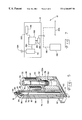
- FIG. 1 is a perspective view of an animal control device according to an embodiment of the present invention.
- FIG. 2 is a perspective view of the pressure pulse generator
- FIG. 3 is a partial cross-sectional perspective view of the pressure pulse generator of FIG. 1.
- FIG. 4 is a view orthogonal to that of FIG. 2, shown in partial cross-section of the pressure pulse generator of FIG. 1 prior to the movement of the impactor;
- FIG. 5 is the pressure pulse generator of FIG. 3 shown with the impactor in its superior position adjacent in the tip;
- FIG. 6 is a diagram depicting the interrelationship of the components of an animal control device according to the present invention.
- FIG. 7 is a diagrammatic view of an animal control device according to an embodiment of the present invention.
- Animal control device includes collar 12 and pressure pulse generator 14 .
- Pressure pulse generator 14 includes enclosure 16 which houses the mechanism by which the pressure pulse generator 14 produces a pressure pulse wave. Extending radially inward from enclosure 16 is probe 18 having tip 20 .
- Collar 12 is adapted to fit around an animal's neck.
- Collar 12 includes an adjustable strap 22 with buckle 24 permitting collar 12 to accommodate the varying sizes of necks of different animals.
- Collar 12 is adjustable to permit tip 20 to be in contact with the skin of an animal's throat when collar 12 is securely fastened around the animal's neck.
- a compression wave is generated within probe 18 and proceeds along tip 20 . The compression wave leaves tip as a pressure pulse wave is applied to the skin of the animal.
- pressure pulse generator 14 is an electronically controlled, pneumatically powered device.
- Pressure pulse generator 14 comprises probe 18 , tip 20 and valve 22 A.
- pressure pulse generator 14 contains a battery, gas cylinder, and a pressure regulator (not shown).
- the battery, gas cylinder and pressure regulator may be any standard commercial design.
- the gas cylinder and pressure regulator provide a gas flow at a constant pressure.
- Solenoid 26 includes input leads 28 attached to windings 30 .
- Windings 30 encircle bobbin 32 which surrounds sleeve 34 and adjustment slug 36 .
- Bobbin 32 and sleeve 34 are constructed of a non-ferrous material.
- Sleeve 34 is retained by cover plate 38 .
- the outer diameter of slug 36 may be threaded to mate with sleeve end 40 so that rotation of adjustment slug 36 causes a proportional translation of slug 36 within sleeve 34 .
- adjustment slug 36 may be adhesively bound or press fit onto sleeve 34 .
- Stem 42 is disposed within sleeve 34 and reciprocates within sleeve 34 . Gap 44 is maintained between bottom face 46 of adjustment slug 36 and top face 48 of stem 42 . Adjustment slug 36 and stem 42 are constructed of a magnetizable material.
- stem 42 is enlarged from a boss 50 with recess 52 which retains an elastomeric disk 54 .
- Compression spring 56 applies a biasing force against stem 42 to press elastomeric disk 54 tightly against tubular boss face 57 of orifice plate 58 .
- Orifice plate 58 includes orifice plate bore 60 which runs through orifice plate 58 and is aligned with manifold bore 62 and manifold plate 64 . Gas flow from a pressure regulator (not shown) enters valve 22 A through tube 24 which is captured in housing bore 66 of housing 68 .
- FIGS. 4 and 5 gas flow enters pressure wave generator 70 from manifold bore 62 through coupling bore 72 of coupling 74 .
- Pressure wave generator 70 includes impactor 76 which translates freely within guide tube 78 .
- FIG. 4 depicts pressure pulse generator 70 prior to activation with impactor 76 disposed in guide tube 78 adjacent coupling bore 72 .
- FIG. 5 depicts the pressure pulse generator 70 when a pressure pulse wave is generated.
- impactor 76 traverse guide tube 78 from its initial position adjacent coupling bore 72 (FIG. 4) to its final position against tip 20 (FIG. 5 ).
- the pressure of gas within guide tube 78 acts against bottom impactor surface 80 .
- a force is applied upon impactor bottom surface 80 which accelerates impactor 76 upward within guide tube 78 .
- the outer diameter of impactor 76 is chosen to be slightly smaller than the inner diameter of guide tube 78 so that the impactor 76 translates freely within guide tube 78 while providing a minimal gas leakage between impactor 76 and guide tube 78 .
- Impactor 76 attains kinetic energy as it transverse the guide tube 76 from coupling end 82 towards distal end 84 where the impactor strikes tip bottom surface 86 of tip 20 .
- Tip end face 88 is in contact with the skin of the animal when the animal control device is properly secured to an animal's neck.
- the surface area of tip end face 88 is a relevant parameter effecting the performance of probe 18 .
- Surface diameters ranging from 1/64 to 3/16, preferably between 3/64 to 3/32 of an inch were found to provide optimal results. As the surface area was reduced below 3/64, possible skin irritation could occur. As the tip surface diameter was increased beyond 3/32, it became difficult to impart sufficient kinetic energy to the impactor to result in an applied pressure pulse of sufficient amplitude to provide adequate discomfort to the animal to discourage difficult to correct behavior such as chasing prey or attacking other animals.
- Tip 20 is free to translate within probe 18 .
- Probe compression spring 90 applies a biasing force against tip 20 to hold tip 20 against ledge 92 of tip bore 94 .
- tip 20 is retracted within tip bore 94 .
- Outlet 96 allows gas flow from guide tube 78 to exit the pressure wave generator 70 through outlet cavity 98 located between guide tube 78 and pressure wave generator wall 100 .
- constant gas pressure is supplied by compressed gas cylinder 110 through pressure regulator 120 to valve 22 A
- An operator uses the correction level selector 140 to adjust the level of correction in terms of the amplitude (i.e., the intensity) of pressure pulse to be generated.
- a consistent or constant gas pressure is supplied to valve 22 A prior to valve 22 A opening.
- Pressure pulse width modulation circuit 150 directs current flow via line 155 to solenoid valve 22 A.
- Mechanical pressure pulse generator 70 produces a pressure pulse wave correction stimulus (block 170 ) having a pulse width corresponding to the correction level selected.
- the correction stimulus is directed to an animal in the form of a negative stimulus to curb undesired behavior.
- a pressure pulse wave of desired width is produced when direct current flows in windings 30 of solenoid 26 (FIG. 3 ).
- the current flow creates a magnetic field which magnetizes adjustment slug 36 and stem 42 .
- Slug 36 and stem 42 attract one another and stem 42 is pulled towards the stationary adjustment slug 36 , thereby closing gap 44 between slug 36 and stem 42 .
- disk 54 is pulled away from orifice plate 58 thereby allowing pressurized gas to flow from the compressed gas cylinder (not shown) and pressure regulator (not shown) through tube 24 and housing bore 66 through orifice bore 60 and on to manifold bore 62 .
- the gas flow enters pressure wave generator 70 where the expanding gas imparts kinetic energy to the impactor 76 as the impactor is propelled in guide tube 78 toward tip bottom surface 86 (FIGS. 4 and 5 ). Gas in guide tube 78 is expelled out through outlet 96 , down through outlet cavity 98 , and out vent 102 (FIG. 2 ).
- Impactor 76 continues transversing guide tube 78 until impactor 76 strikes tip bottom surface 86 (FIG. 5 ).
- a mechanical compression wave is generated as a result of impactor 76 striking tip bottom surface 86 .
- the mechanical compression wave travels along tip 20 from tip bottom surface 86 to tip end 88 .
- the action of the compression wave traveling through tip 20 causes a slight upward (i.e., radially inward relative to collar 12 ) displacement of tip 20 thereby compressing probe compression spring 90 .
- the compression wave leaves the tip 20 as a pressure wave pulse that enters the animal's skin.
- the pressure wave pulse excites local neurons within the animal's neck. The excitation of local neurons provides a mode of stimulus to an animal to effect correction of an animal's undesired behavior.
- probe compression spring 90 returns tip 20 to its pre-impact position. Impactor 76 is pushed by the action of tip 20 returning to its initial position and impactor 76 continues to travel away from tip 20 under the influence of the push from tip 20 moving to its initial position.
- the intensity of the pressure wave pulse is related to the volume of gas supplied behind impactor 76 . Therefore, it is possible to adjust the intensity of the pressure wave pulse applied to an animal by varying the volume of gas supplied behind impactor 76 .
- the volume of gas supplied behind impactor 76 is determined by the length of time solenoid valve 22 A is open.
- the length of time solenoid valve 22 A is open is controlled by the length of time a current flow is supplied to solenoid windings 30 .
- the length of time current flow is supplied to windings 30 is operator selectable via correction level selector 140 operatively associated with pulse width modulation circuit 150 (FIG. 6 ).
- the animal control device may be selected to apply a pressure pulse from a maximum pressure wave pulse to a minimum pressure wave pulse.
- a maximum pressure wave pulse is produced when current flow is supplied to solenoid 22 A at a maximum duration.
- the maximum duration is the length of time sufficient to allow a volume of gas to be introduced behind impactor 76 such that the pressure of the gas remains constant as impactor 76 completely transverses guide tube 78 and strikes tip 20 .
- the current flow duration decreases from its maximum, the volume of gas introduced behind the impactor becomes insufficient to maintain a constant pressure as impactor 76 moves along guide tube towards tip 18 and the volume behind the impactor increases.
- the increase in volume behind impactor 76 results in a proportional decrease in gas pressure as impactor 76 transverses in guide tube 78 .
- the resulting force applied by the expanding gas behind impactor 76 similarly decreases with an associated reduction in impactor 76 velocity and kinetic energy at the instant of impact of impactor 76 with tip 20 .
- a lower amplitude compression wave is propagated through the tip 20 with an associated reduction in amplitude of pressure wave pulse applied to an animal's skin. Successive reductions in current flow duration result in proportional reduction in the correction stimulus level.
- FIG. 7 depicts a diagrammatic view of one particular embodiment of animal control device 10 .
- Hand held remote 180 is used to set the intensity and to direct a command to apply a pressure wave pulse to an animal to control undesired behavior.
- Hand held remote 180 transmits an RF signal 182 to receiver 184 .
- Receiver 184 sends a receiver signal via line 186 to controller 188 .
- Controller 188 receives the signal over line 186 and outputs a signal via line 190 representing the current flow duration corresponding to the intensity selected via the handheld remote 180 .
- Current flow via line 190 is directed to pressure pulse generator 14 which in turn produces a corresponding pressure wave pulse 194 corresponding to the intensity selected.
- a plurality of sensors may be operatively associated with controller 188 .
- a barking sensor 196 detects an animal's barking as an audio signal and directs a barking signal over line 202 to controller 188 which in turn administers a pressure pulse wave to the animal as a negative stimulus in response to the barking animal.
- animal control device 10 may be sensitive to a wire 206 or a boundary transmitter (not shown) present within an area which is used to confine an animal. For example, if the animal were to stray outside a selected area, or approach a buried wire 206 , receiver 184 directs a signal over line 186 to controller 188 which in turn initiates a pressure pulse wave by pressure wave generator 70 .
- a boundary transmitter (not shown) could be disposed inside an area in which the animal is prohibited.
- receiver 184 receives the transmitted signal and a pressure pulse wave is generated as a negative stimulus to the animal. Consequently, the animal's improper behavior of entering a restricted area is deterred. Thus, an animal's behavior may be monitored and controlled without human monitoring.
Abstract
Description
Claims (13)
Priority Applications (2)
| Application Number | Priority Date | Filing Date | Title |
|---|---|---|---|
| US09/442,288 US6360697B1 (en) | 1999-11-19 | 1999-11-19 | Pressure pulse probe for animal behavior correction |
| US10/037,197 US6830013B2 (en) | 1999-11-19 | 2001-11-09 | Pressure pulse probe for animal behavior correction |
Applications Claiming Priority (1)
| Application Number | Priority Date | Filing Date | Title |
|---|---|---|---|
| US09/442,288 US6360697B1 (en) | 1999-11-19 | 1999-11-19 | Pressure pulse probe for animal behavior correction |
Related Child Applications (1)
| Application Number | Title | Priority Date | Filing Date |
|---|---|---|---|
| US10/037,197 Continuation US6830013B2 (en) | 1999-11-19 | 2001-11-09 | Pressure pulse probe for animal behavior correction |
Publications (1)
| Publication Number | Publication Date |
|---|---|
| US6360697B1 true US6360697B1 (en) | 2002-03-26 |
Family
ID=23756247
Family Applications (2)
| Application Number | Title | Priority Date | Filing Date |
|---|---|---|---|
| US09/442,288 Expired - Lifetime US6360697B1 (en) | 1999-11-19 | 1999-11-19 | Pressure pulse probe for animal behavior correction |
| US10/037,197 Expired - Lifetime US6830013B2 (en) | 1999-11-19 | 2001-11-09 | Pressure pulse probe for animal behavior correction |
Family Applications After (1)
| Application Number | Title | Priority Date | Filing Date |
|---|---|---|---|
| US10/037,197 Expired - Lifetime US6830013B2 (en) | 1999-11-19 | 2001-11-09 | Pressure pulse probe for animal behavior correction |
Country Status (1)
| Country | Link |
|---|---|
| US (2) | US6360697B1 (en) |
Cited By (40)
| Publication number | Priority date | Publication date | Assignee | Title |
|---|---|---|---|---|
| US20020152970A1 (en) * | 2000-08-21 | 2002-10-24 | Takeshi Takeda | Method and device for communication with animal |
| US6712025B2 (en) * | 2000-10-13 | 2004-03-30 | Dogwatch, Inc. | Receiver/stimulus unit for an animal control system |
| US20040073146A1 (en) * | 2001-03-05 | 2004-04-15 | David Weintraub | Portable device for the enhancement of circulation and for the prevention of stasis related dvt |
| US6830014B1 (en) | 2003-08-05 | 2004-12-14 | Tom Lalor | Animal collar |
| US6830013B2 (en) * | 1999-11-19 | 2004-12-14 | Innotek, Inc. | Pressure pulse probe for animal behavior correction |
| US20050065670A1 (en) * | 2003-08-13 | 2005-03-24 | Helmut Tripmaker | System and method for exchanging programs in aircraft computers |
| US20050061259A1 (en) * | 2003-08-05 | 2005-03-24 | Tom Lalor | Animal collar |
| US20050145194A1 (en) * | 2003-11-21 | 2005-07-07 | Brian Lange | Vibrating livestock prod with pneumatic actuation |
| US20050145201A1 (en) * | 2003-12-31 | 2005-07-07 | Radio Systems Corporation | Intensity variation device for training animals |
| US20050263099A1 (en) * | 2004-05-06 | 2005-12-01 | Gerig Duane A | Rising stimulation modification |
| US7046152B1 (en) | 2003-12-10 | 2006-05-16 | Innotek, Inc. | Method and apparatus for communicating control signals |
| US20060112905A1 (en) * | 2003-08-05 | 2006-06-01 | Tom Lalor | Animal collar |
| US7068174B1 (en) | 2003-12-10 | 2006-06-27 | Innotek, Inc. | Method and apparatus for communicating an animal control signal |
| US7117822B1 (en) | 2003-12-10 | 2006-10-10 | Innotek, Inc. | Method and apparatus for communicating a randomized signal |
| US20080156277A1 (en) * | 2007-01-03 | 2008-07-03 | Radio Systems Corporation | Animal Training Device Using a Vibration Probe to Deliver a Vibration Stimulus to an Animal |
| US20080245316A1 (en) * | 2003-12-10 | 2008-10-09 | Radio Systems Corporation | Method and Apparatus for Varying Animal Correction Signals |
| US20090119962A1 (en) * | 2007-11-13 | 2009-05-14 | Bruce De La Cruz | Methods and apparatuses for the display of promotional images |
| US20100050955A1 (en) * | 2008-09-03 | 2010-03-04 | Pacheco Alfred D | Animal training systems and methods for training animals not to pull excessively on leads |
| US20110221597A1 (en) * | 2010-03-11 | 2011-09-15 | Jameson James L | Animal Training Device Having a Programmable Stimulus Delivery Switch |
| USD665952S1 (en) * | 2012-01-16 | 2012-08-21 | Guo xu wei | Receiver |
| USD673334S1 (en) * | 2012-01-16 | 2012-12-25 | Guo xu wei | Receiver |
| USD788999S1 (en) | 2016-03-11 | 2017-06-06 | Radio Systems Corporation | Receiver for a pet collar |
| US20180132450A1 (en) * | 2011-12-05 | 2018-05-17 | Radio Systems Corporation | Piezoelectric detection coupling of a bark collar |
| US10154651B2 (en) | 2011-12-05 | 2018-12-18 | Radio Systems Corporation | Integrated dog tracking and stimulus delivery system |
| US10231440B2 (en) | 2015-06-16 | 2019-03-19 | Radio Systems Corporation | RF beacon proximity determination enhancement |
| US10375930B1 (en) * | 2017-07-07 | 2019-08-13 | Chad R. James | Animal training device that controls stimulus using proportional pressure-based input |
| USD858904S1 (en) | 2017-06-05 | 2019-09-03 | Radio Systems Corporation | Receiver for pet collar |
| US10514439B2 (en) | 2017-12-15 | 2019-12-24 | Radio Systems Corporation | Location based wireless pet containment system using single base unit |
| USD880082S1 (en) | 2016-03-11 | 2020-03-31 | Radio Systems Corporation | Receiver for a pet collar |
| US10613559B2 (en) | 2016-07-14 | 2020-04-07 | Radio Systems Corporation | Apparatus, systems and methods for generating voltage excitation waveforms |
| US10645908B2 (en) | 2015-06-16 | 2020-05-12 | Radio Systems Corporation | Systems and methods for providing a sound masking environment |
| US10674709B2 (en) * | 2011-12-05 | 2020-06-09 | Radio Systems Corporation | Piezoelectric detection coupling of a bark collar |
| US10842128B2 (en) | 2017-12-12 | 2020-11-24 | Radio Systems Corporation | Method and apparatus for applying, monitoring, and adjusting a stimulus to a pet |
| US10986813B2 (en) | 2017-12-12 | 2021-04-27 | Radio Systems Corporation | Method and apparatus for applying, monitoring, and adjusting a stimulus to a pet |
| US11109182B2 (en) | 2017-02-27 | 2021-08-31 | Radio Systems Corporation | Threshold barrier system |
| US11238889B2 (en) | 2019-07-25 | 2022-02-01 | Radio Systems Corporation | Systems and methods for remote multi-directional bark deterrence |
| US11372077B2 (en) | 2017-12-15 | 2022-06-28 | Radio Systems Corporation | Location based wireless pet containment system using single base unit |
| US11394196B2 (en) | 2017-11-10 | 2022-07-19 | Radio Systems Corporation | Interactive application to protect pet containment systems from external surge damage |
| US11490597B2 (en) | 2020-07-04 | 2022-11-08 | Radio Systems Corporation | Systems, methods, and apparatus for establishing keep out zones within wireless containment regions |
| US11553692B2 (en) | 2011-12-05 | 2023-01-17 | Radio Systems Corporation | Piezoelectric detection coupling of a bark collar |
Families Citing this family (13)
| Publication number | Priority date | Publication date | Assignee | Title |
|---|---|---|---|---|
| WO2005051184A1 (en) * | 2003-11-28 | 2005-06-09 | Koninklijke Philips Electronics N.V. | Monitoring device and a monitoring body-wear |
| US7222589B2 (en) * | 2004-04-23 | 2007-05-29 | Radio Systems Corporation | Bark control device and associated vibration dampening housing and method for constructing such housing |
| US20070028853A1 (en) * | 2005-08-04 | 2007-02-08 | Radio Systems Corporation | Pet confinement system using ultra wideband |
| US20070113797A1 (en) * | 2005-11-21 | 2007-05-24 | Radio Systems Corporation | Electrical pet gate |
| JP2011505925A (en) * | 2007-04-11 | 2011-03-03 | スター ライフ サイエンシーズ コーポレイション | Non-invasive photoplethysmographic sensor platform for mobile animals |
| US20090013939A1 (en) * | 2007-07-13 | 2009-01-15 | Whitlock International, L.L.C. | Apparatus and method for restricting movement of an animal into or out of a defined area |
| US7707974B2 (en) * | 2007-07-25 | 2010-05-04 | Radio Systems Corporation | LCD window for animal training device and method for manufacture |
| US7992525B1 (en) * | 2007-12-31 | 2011-08-09 | Fisher Terri L | Animal training device |
| WO2010040246A1 (en) * | 2008-10-07 | 2010-04-15 | Huo William | Collar used for pet training |
| US8161915B2 (en) * | 2010-01-19 | 2012-04-24 | Yong Won Kim | Apparatus for preventing animal from barking and method of controlling the same |
| US9615542B2 (en) * | 2010-02-25 | 2017-04-11 | Radio Systems Corporation | Mechanically compliant probe for delivering an electrical stimulus to an animal |
| WO2013133918A1 (en) * | 2012-03-09 | 2013-09-12 | Bellon Bart | Improved animal collar with integrated electronics |
| CN107960342A (en) * | 2017-11-29 | 2018-04-27 | 深圳市沃特沃德股份有限公司 | Intelligence stops method and device of barking |
Citations (13)
| Publication number | Priority date | Publication date | Assignee | Title |
|---|---|---|---|---|
| US3874339A (en) * | 1974-06-26 | 1975-04-01 | John Coulbourn | Anti-pull animal leash mechanism |
| FR2625646A1 (en) * | 1988-01-07 | 1989-07-13 | Vinci Rene | Anti-bark collar |
| US5099797A (en) * | 1990-01-11 | 1992-03-31 | Tri-Tronics, Inc. | Electrode structure for collar mounted animal training apparatus |
| US5207178A (en) * | 1992-01-31 | 1993-05-04 | Invisible Fence Company, Inc. | Electrode device for an electric shock generator carried on an animal collar |
| FR2700665A1 (en) * | 1993-01-26 | 1994-07-29 | Jardin Marc | Training device for a dog or other pet |
| JPH07297930A (en) * | 1994-04-28 | 1995-11-10 | Nippon Telegr & Teleph Corp <Ntt> | Device and method for transferring telephone call |
| US5533469A (en) * | 1993-08-18 | 1996-07-09 | Invisible Fence Company, Inc. | Programming apparatus for programmable animal control device |
| US5559498A (en) * | 1994-12-30 | 1996-09-24 | Innotek Inc. | Combination confinement and remote training system |
| US5606116A (en) * | 1994-10-29 | 1997-02-25 | Kabushiki Kaisha Nippon Gene | Chromatogenous testing system for urinalysis |
| US5666908A (en) * | 1995-07-05 | 1997-09-16 | So; Ho Yun | Animal training device |
| US5815077A (en) * | 1995-11-21 | 1998-09-29 | B.E.R.T.S. Inc. | Electronic collar for locating and training animals |
| US5857433A (en) * | 1996-07-22 | 1999-01-12 | John C. Files | Animal training and tracking device having global positioning satellite unit |
| US5911198A (en) * | 1996-08-05 | 1999-06-15 | Innotek Pet Products, Inc. | Animal stimulator |
Family Cites Families (2)
| Publication number | Priority date | Publication date | Assignee | Title |
|---|---|---|---|---|
| US2394144A (en) * | 1944-12-14 | 1946-02-05 | Horace B Brose | Force collar |
| US6360697B1 (en) * | 1999-11-19 | 2002-03-26 | Innotek, Inc. | Pressure pulse probe for animal behavior correction |
-
1999
- 1999-11-19 US US09/442,288 patent/US6360697B1/en not_active Expired - Lifetime
-
2001
- 2001-11-09 US US10/037,197 patent/US6830013B2/en not_active Expired - Lifetime
Patent Citations (13)
| Publication number | Priority date | Publication date | Assignee | Title |
|---|---|---|---|---|
| US3874339A (en) * | 1974-06-26 | 1975-04-01 | John Coulbourn | Anti-pull animal leash mechanism |
| FR2625646A1 (en) * | 1988-01-07 | 1989-07-13 | Vinci Rene | Anti-bark collar |
| US5099797A (en) * | 1990-01-11 | 1992-03-31 | Tri-Tronics, Inc. | Electrode structure for collar mounted animal training apparatus |
| US5207178A (en) * | 1992-01-31 | 1993-05-04 | Invisible Fence Company, Inc. | Electrode device for an electric shock generator carried on an animal collar |
| FR2700665A1 (en) * | 1993-01-26 | 1994-07-29 | Jardin Marc | Training device for a dog or other pet |
| US5533469A (en) * | 1993-08-18 | 1996-07-09 | Invisible Fence Company, Inc. | Programming apparatus for programmable animal control device |
| JPH07297930A (en) * | 1994-04-28 | 1995-11-10 | Nippon Telegr & Teleph Corp <Ntt> | Device and method for transferring telephone call |
| US5606116A (en) * | 1994-10-29 | 1997-02-25 | Kabushiki Kaisha Nippon Gene | Chromatogenous testing system for urinalysis |
| US5559498A (en) * | 1994-12-30 | 1996-09-24 | Innotek Inc. | Combination confinement and remote training system |
| US5666908A (en) * | 1995-07-05 | 1997-09-16 | So; Ho Yun | Animal training device |
| US5815077A (en) * | 1995-11-21 | 1998-09-29 | B.E.R.T.S. Inc. | Electronic collar for locating and training animals |
| US5857433A (en) * | 1996-07-22 | 1999-01-12 | John C. Files | Animal training and tracking device having global positioning satellite unit |
| US5911198A (en) * | 1996-08-05 | 1999-06-15 | Innotek Pet Products, Inc. | Animal stimulator |
Cited By (62)
| Publication number | Priority date | Publication date | Assignee | Title |
|---|---|---|---|---|
| US6830013B2 (en) * | 1999-11-19 | 2004-12-14 | Innotek, Inc. | Pressure pulse probe for animal behavior correction |
| US20020152970A1 (en) * | 2000-08-21 | 2002-10-24 | Takeshi Takeda | Method and device for communication with animal |
| US6712025B2 (en) * | 2000-10-13 | 2004-03-30 | Dogwatch, Inc. | Receiver/stimulus unit for an animal control system |
| US20040073146A1 (en) * | 2001-03-05 | 2004-04-15 | David Weintraub | Portable device for the enhancement of circulation and for the prevention of stasis related dvt |
| US20050061259A1 (en) * | 2003-08-05 | 2005-03-24 | Tom Lalor | Animal collar |
| US7243617B2 (en) | 2003-08-05 | 2007-07-17 | Tom Lalor | Animal collar |
| US6830014B1 (en) | 2003-08-05 | 2004-12-14 | Tom Lalor | Animal collar |
| US7562640B2 (en) | 2003-08-05 | 2009-07-21 | Tom Lalor | Animal collar |
| US20080210176A1 (en) * | 2003-08-05 | 2008-09-04 | Tom Lalor | Animal collar |
| US7267082B2 (en) | 2003-08-05 | 2007-09-11 | Tom Lalor | Animal collar |
| US20060112905A1 (en) * | 2003-08-05 | 2006-06-01 | Tom Lalor | Animal collar |
| US20050065670A1 (en) * | 2003-08-13 | 2005-03-24 | Helmut Tripmaker | System and method for exchanging programs in aircraft computers |
| US20050145194A1 (en) * | 2003-11-21 | 2005-07-07 | Brian Lange | Vibrating livestock prod with pneumatic actuation |
| US7204204B1 (en) | 2003-12-10 | 2007-04-17 | Innotek, Inc. | Method for creating an avoidance zone |
| US7495570B1 (en) | 2003-12-10 | 2009-02-24 | Innotek, Inc. | Transmitter apparatus |
| US8342135B2 (en) | 2003-12-10 | 2013-01-01 | Radio Systems Corporation | Method and apparatus for varying animal correction signals |
| US7117822B1 (en) | 2003-12-10 | 2006-10-10 | Innotek, Inc. | Method and apparatus for communicating a randomized signal |
| US7068174B1 (en) | 2003-12-10 | 2006-06-27 | Innotek, Inc. | Method and apparatus for communicating an animal control signal |
| US7046152B1 (en) | 2003-12-10 | 2006-05-16 | Innotek, Inc. | Method and apparatus for communicating control signals |
| US7278376B1 (en) | 2003-12-10 | 2007-10-09 | Innotek, Inc. | Method of transmitting a signal for controlling an animal |
| US20080245316A1 (en) * | 2003-12-10 | 2008-10-09 | Radio Systems Corporation | Method and Apparatus for Varying Animal Correction Signals |
| US7017524B2 (en) * | 2003-12-31 | 2006-03-28 | Radio Systems Corporation | Intensity variation device for training animals |
| US20050145201A1 (en) * | 2003-12-31 | 2005-07-07 | Radio Systems Corporation | Intensity variation device for training animals |
| US7360505B2 (en) | 2004-05-06 | 2008-04-22 | Innotek, Inc. | Rising stimulation modification |
| US7343879B2 (en) | 2004-05-06 | 2008-03-18 | Innotek, Inc. | Rising stimulation modification |
| US20050263099A1 (en) * | 2004-05-06 | 2005-12-01 | Gerig Duane A | Rising stimulation modification |
| US7174855B2 (en) * | 2004-05-06 | 2007-02-13 | Innotek, Inc. | Rising stimulation modification |
| US20080156277A1 (en) * | 2007-01-03 | 2008-07-03 | Radio Systems Corporation | Animal Training Device Using a Vibration Probe to Deliver a Vibration Stimulus to an Animal |
| WO2008085812A2 (en) | 2007-01-03 | 2008-07-17 | Radio Systems Corporation | An animal training device using a vibration probe to deliver a vibration stimulus to an animal |
| EP2109360A4 (en) * | 2007-01-03 | 2012-12-26 | Radio Systems Corp | An animal training device using a vibration probe to deliver a vibration stimulus to an animal |
| EP2109360A2 (en) * | 2007-01-03 | 2009-10-21 | Radio Systems Corporation | An animal training device using a vibration probe to deliver a vibration stimulus to an animal |
| US20090119962A1 (en) * | 2007-11-13 | 2009-05-14 | Bruce De La Cruz | Methods and apparatuses for the display of promotional images |
| US20100050955A1 (en) * | 2008-09-03 | 2010-03-04 | Pacheco Alfred D | Animal training systems and methods for training animals not to pull excessively on leads |
| US8402924B2 (en) | 2008-09-03 | 2013-03-26 | Merren, Llc | Animal training systems and methods for training animals not to pull excessively on leads |
| US20110221597A1 (en) * | 2010-03-11 | 2011-09-15 | Jameson James L | Animal Training Device Having a Programmable Stimulus Delivery Switch |
| US11553692B2 (en) | 2011-12-05 | 2023-01-17 | Radio Systems Corporation | Piezoelectric detection coupling of a bark collar |
| US20180132450A1 (en) * | 2011-12-05 | 2018-05-17 | Radio Systems Corporation | Piezoelectric detection coupling of a bark collar |
| US10154651B2 (en) | 2011-12-05 | 2018-12-18 | Radio Systems Corporation | Integrated dog tracking and stimulus delivery system |
| US11470814B2 (en) * | 2011-12-05 | 2022-10-18 | Radio Systems Corporation | Piezoelectric detection coupling of a bark collar |
| US10674709B2 (en) * | 2011-12-05 | 2020-06-09 | Radio Systems Corporation | Piezoelectric detection coupling of a bark collar |
| USD673334S1 (en) * | 2012-01-16 | 2012-12-25 | Guo xu wei | Receiver |
| USD665952S1 (en) * | 2012-01-16 | 2012-08-21 | Guo xu wei | Receiver |
| US10645908B2 (en) | 2015-06-16 | 2020-05-12 | Radio Systems Corporation | Systems and methods for providing a sound masking environment |
| US10231440B2 (en) | 2015-06-16 | 2019-03-19 | Radio Systems Corporation | RF beacon proximity determination enhancement |
| USD880082S1 (en) | 2016-03-11 | 2020-03-31 | Radio Systems Corporation | Receiver for a pet collar |
| USD788999S1 (en) | 2016-03-11 | 2017-06-06 | Radio Systems Corporation | Receiver for a pet collar |
| US10613559B2 (en) | 2016-07-14 | 2020-04-07 | Radio Systems Corporation | Apparatus, systems and methods for generating voltage excitation waveforms |
| US11109182B2 (en) | 2017-02-27 | 2021-08-31 | Radio Systems Corporation | Threshold barrier system |
| USD858904S1 (en) | 2017-06-05 | 2019-09-03 | Radio Systems Corporation | Receiver for pet collar |
| US11805754B2 (en) * | 2017-07-07 | 2023-11-07 | Cje Products, Llc | Animal training device that controls stimulus using proportional pressure-based input |
| US20190246604A1 (en) * | 2017-07-07 | 2019-08-15 | Chad R. James | Animal training device that controls stimulus using proportional pressure-based input |
| US10375930B1 (en) * | 2017-07-07 | 2019-08-13 | Chad R. James | Animal training device that controls stimulus using proportional pressure-based input |
| US20230042381A1 (en) * | 2017-07-07 | 2023-02-09 | Cje Products, Llc | Animal training device that controls stimulus using proportional pressure-based input |
| US11470816B2 (en) | 2017-07-07 | 2022-10-18 | Cje Products, Llc | Animal training device that controls stimulus using proportional pressure-based input |
| US11394196B2 (en) | 2017-11-10 | 2022-07-19 | Radio Systems Corporation | Interactive application to protect pet containment systems from external surge damage |
| US10986813B2 (en) | 2017-12-12 | 2021-04-27 | Radio Systems Corporation | Method and apparatus for applying, monitoring, and adjusting a stimulus to a pet |
| US10842128B2 (en) | 2017-12-12 | 2020-11-24 | Radio Systems Corporation | Method and apparatus for applying, monitoring, and adjusting a stimulus to a pet |
| US11372077B2 (en) | 2017-12-15 | 2022-06-28 | Radio Systems Corporation | Location based wireless pet containment system using single base unit |
| US10955521B2 (en) | 2017-12-15 | 2021-03-23 | Radio Systems Corporation | Location based wireless pet containment system using single base unit |
| US10514439B2 (en) | 2017-12-15 | 2019-12-24 | Radio Systems Corporation | Location based wireless pet containment system using single base unit |
| US11238889B2 (en) | 2019-07-25 | 2022-02-01 | Radio Systems Corporation | Systems and methods for remote multi-directional bark deterrence |
| US11490597B2 (en) | 2020-07-04 | 2022-11-08 | Radio Systems Corporation | Systems, methods, and apparatus for establishing keep out zones within wireless containment regions |
Also Published As
| Publication number | Publication date |
|---|---|
| US20020073932A1 (en) | 2002-06-20 |
| US6830013B2 (en) | 2004-12-14 |
Similar Documents
| Publication | Publication Date | Title |
|---|---|---|
| US6360697B1 (en) | Pressure pulse probe for animal behavior correction | |
| US7174856B2 (en) | Method and apparatus for animal behavior modification | |
| US5911199A (en) | Pressure sensitive animal training device | |
| US4539937A (en) | Controlled shock animal training device | |
| US5494002A (en) | Animal training device | |
| US4202293A (en) | Dog training collars and methods | |
| CN110769686A (en) | Pet spraying training system | |
| EP2109360B1 (en) | An animal training device using a vibration probe to deliver a vibration stimulus to an animal | |
| US8763563B2 (en) | Leash and collar for animal control | |
| US8069823B2 (en) | Vibration stimulus delivery device | |
| EP0340278B1 (en) | Anti-barking collar | |
| US6230660B1 (en) | Apparatus for controlling insects on an animal | |
| JPH051688B2 (en) | ||
| US7267082B2 (en) | Animal collar | |
| CA2334019A1 (en) | Animal restraining halter | |
| US6612264B2 (en) | Dog leash training device | |
| EP1452091A3 (en) | Method and apparatus for reducing risk that a thrown toy will injure an animal | |
| US20190230904A1 (en) | Device producing sound when leash tautness is reduced | |
| US5758603A (en) | Application of a pesticide to an animal | |
| US8037848B2 (en) | Animal behavioral control apparatus | |
| US20170142932A1 (en) | Pet Spray Training System | |
| US6101980A (en) | Combination collar | |
| US5722352A (en) | Apparatus and method for reducing equine cribbing behavior | |
| US20210076642A1 (en) | Training apparatus | |
| US3273657A (en) | Impact tool |
Legal Events
| Date | Code | Title | Description |
|---|---|---|---|
| AS | Assignment |
Owner name: INNOTEK, INC., INDIANA Free format text: ASSIGNMENT OF ASSIGNORS INTEREST;ASSIGNOR:WILLIAMS, MATTHEW R.;REEL/FRAME:010414/0727 Effective date: 19991105 |
|
| STCF | Information on status: patent grant |
Free format text: PATENTED CASE |
|
| CC | Certificate of correction | ||
| AS | Assignment |
Owner name: NATIONAL CITY BANK, OHIO Free format text: SECURITY AGREEMENT;ASSIGNOR:INNOTEK, INC.;REEL/FRAME:016580/0060 Effective date: 20010125 |
|
| FPAY | Fee payment |
Year of fee payment: 4 |
|
| AS | Assignment |
Owner name: FIFTH THIRD BANK, AS ADMINISTRATIVE AGENT,OHIO Free format text: SECURITY INTEREST;ASSIGNOR:INNOTEK, INC.;REEL/FRAME:018291/0913 Effective date: 20060915 Owner name: FIFTH THIRD BANK, AS ADMINISTRATIVE AGENT, OHIO Free format text: SECURITY INTEREST;ASSIGNOR:INNOTEK, INC.;REEL/FRAME:018291/0913 Effective date: 20060915 |
|
| AS | Assignment |
Owner name: INNOTEK, INC., INDIANA Free format text: RELEASE OF ASSIGNMENT;ASSIGNOR:NATIONAL CITY BANK;REEL/FRAME:018323/0501 Effective date: 20060915 |
|
| AS | Assignment |
Owner name: INNOTEK, INC., INDIANA Free format text: RELEASE OF SECURITY AGREEMENT RECORDED ON SEPTEMBER 23, 2005 AT REEL/FRAME NO. 016580/0060;ASSIGNOR:NATIONAL CITY BANK;REEL/FRAME:018303/0629 Effective date: 20060914 |
|
| FPAY | Fee payment |
Year of fee payment: 8 |
|
| AS | Assignment |
Owner name: THE BANK OF NEW YORK MELLON TRUST COMPANY, N.A., F Free format text: SECURITY AGREEMENT;ASSIGNORS:RADIO SYSTEMS CORPORATION;INNOTEK, INC.;INVISIBLE FENCE, INC.;REEL/FRAME:029308/0434 Effective date: 20121023 Owner name: THE BANK OF NEW YORK MELLON TRUST COMPANY, N.A., F Free format text: SECURITY AGREEMENT;ASSIGNORS:RADIO SYSTEMS CORPORATION;INNOTEK, INC.;INVISIBLE FENCE, INC.;REEL/FRAME:029308/0001 Effective date: 20121023 |
|
| FEPP | Fee payment procedure |
Free format text: PAT HOLDER NO LONGER CLAIMS SMALL ENTITY STATUS, ENTITY STATUS SET TO UNDISCOUNTED (ORIGINAL EVENT CODE: STOL); ENTITY STATUS OF PATENT OWNER: LARGE ENTITY |
|
| FPAY | Fee payment |
Year of fee payment: 12 |
|
| AS | Assignment |
Owner name: THE BANK OF NEW YORK MELLON TRUST COMPANY, N.A., F Free format text: CORRECTIVE ASSIGNMENT TO CORRECT THE ASSIGNMENT DOCUMENT WHICH INCORRECTLY IDENTIFIED PATENT APP. NO. 13/302,477 PREVIOUSLY RECORDED ON REEL 029308 FRAME 0001. ASSIGNOR(S) HEREBY CONFIRMS THE SECURITY INTEREST;ASSIGNORS:RADIO SYSTEMS CORPORATION;INVISIBLE FENCE, INC.;INNOTEK, INC.;REEL/FRAME:037127/0491 Effective date: 20150929 |
|
| AS | Assignment |
Owner name: THE BANK OF NEW YORK MELLON TRUST COMPANY, N.A., F Free format text: CORRECTIVE ASSIGNMENT TO CORRECT THE INCORRECT PATENT NO. 7814565 PREVIOUSLY RECORDED AT REEL: 029308 FRAME: 0001. ASSIGNOR(S) HEREBY CONFIRMS THE SECURITY AGREEMENT;ASSIGNORS:RADIO SYSTEMS CORPORATION;INNOTEK, INC.;INVISIBLE FENCE, INC.;REEL/FRAME:038332/0343 Effective date: 20121023 |
|
| AS | Assignment |
Owner name: THE BANK OF NEW YORK MELLON TRUST COMPANY, N.A., F Free format text: CORRECTIVE ASSIGNMENT TO CORRECT THE INCORRECT PATENT NO. 7814565 PREVIOUSLY RECORDED AT REEL: 037127 FRAME: 0491. ASSIGNOR(S) HEREBY CONFIRMS THE SECURITY INTEREST;ASSIGNORS:RADIO SYSTEMS CORPORATION;INVISIBLE FENCE, INC.;INNOTEK, INC.;REEL/FRAME:038601/0757 Effective date: 20150929 |
|
| AS | Assignment |
Owner name: FIFTH THIRD BANK, AS ADMINISTRATIVE AGENT, OHIO Free format text: SECURITY AGREEMENT;ASSIGNOR:INNOTEK, INC.;REEL/FRAME:042409/0945 Effective date: 20170502 |
|
| AS | Assignment |
Owner name: RADIO SYSTEMS CORPORATION, TENNESSEE Free format text: RELEASE BY SECURED PARTY;ASSIGNOR:THE BANK OF NEW YORK MELLON TRUST COMPANY, N.A.;REEL/FRAME:043038/0291 Effective date: 20170502 Owner name: INNOTEK, INC., TENNESSEE Free format text: RELEASE BY SECURED PARTY;ASSIGNOR:THE BANK OF NEW YORK MELLON TRUST COMPANY, N.A.;REEL/FRAME:043038/0291 Effective date: 20170502 Owner name: INVISIBLE FENCE, INC., TENNESSEE Free format text: RELEASE BY SECURED PARTY;ASSIGNOR:THE BANK OF NEW YORK MELLON TRUST COMPANY, N.A.;REEL/FRAME:043038/0291 Effective date: 20170502 |
|
| AS | Assignment |
Owner name: INNOTEK, INC., TENNESSEE Free format text: RELEASE OF SECURITY INTEREST IN PATENTS;ASSIGNOR:FIFTH THIRD BANK;REEL/FRAME:053122/0378 Effective date: 20200701 Owner name: RADIO SYSTEMS CORPORATION, TENNESSEE Free format text: RELEASE OF SECURITY INTEREST IN PATENTS;ASSIGNOR:FIFTH THIRD BANK;REEL/FRAME:053122/0378 Effective date: 20200701 Owner name: PREMIER PET PRODUCTS, LLC, TENNESSEE Free format text: RELEASE OF SECURITY INTEREST IN PATENTS;ASSIGNOR:FIFTH THIRD BANK;REEL/FRAME:053122/0344 Effective date: 20200701 Owner name: INNOTEK, INC., TENNESSEE Free format text: RELEASE OF SECURITY INTEREST IN PATENTS;ASSIGNOR:FIFTH THIRD BANK;REEL/FRAME:053122/0268 Effective date: 20200701 Owner name: INVISIBLE FENCE, INC., TENNESSEE Free format text: RELEASE OF SECURITY INTEREST IN PATENTS;ASSIGNOR:FIFTH THIRD BANK;REEL/FRAME:053122/0453 Effective date: 20200701 Owner name: PREMIER PET PRODUCTS, LLC, TENNESSEE Free format text: RELEASE OF SECURITY INTEREST IN PATENTS;ASSIGNOR:FIFTH THIRD BANK;REEL/FRAME:053122/0268 Effective date: 20200701 Owner name: INNOTEK, INC., TENNESSEE Free format text: RELEASE OF SECURITY INTEREST IN PATENTS;ASSIGNOR:FIFTH THIRD BANK;REEL/FRAME:053122/0453 Effective date: 20200701 Owner name: RADIO SYSTEMS CORPORATION, TENNESSEE Free format text: RELEASE OF SECURITY INTEREST IN PATENTS;ASSIGNOR:FIFTH THIRD BANK;REEL/FRAME:053122/0268 Effective date: 20200701 Owner name: PREMIER PET PRODUCTS, LLC, TENNESSEE Free format text: RELEASE OF SECURITY INTEREST IN PATENTS;ASSIGNOR:FIFTH THIRD BANK;REEL/FRAME:053122/0378 Effective date: 20200701 Owner name: RADIO SYSTEMS CORPORATION, TENNESSEE Free format text: RELEASE OF SECURITY INTEREST IN PATENTS;ASSIGNOR:FIFTH THIRD BANK;REEL/FRAME:053122/0344 Effective date: 20200701 Owner name: INNOTEK, INC., TENNESSEE Free format text: RELEASE OF SECURITY INTEREST IN PATENTS;ASSIGNOR:FIFTH THIRD BANK;REEL/FRAME:053122/0344 Effective date: 20200701 Owner name: INVISIBLE FENCE, INC., TENNESSEE Free format text: RELEASE OF SECURITY INTEREST IN PATENTS;ASSIGNOR:FIFTH THIRD BANK;REEL/FRAME:053122/0378 Effective date: 20200701 Owner name: PREMIER PET PRODUCTS, LLC, TENNESSEE Free format text: RELEASE OF SECURITY INTEREST IN PATENTS;ASSIGNOR:FIFTH THIRD BANK;REEL/FRAME:053122/0453 Effective date: 20200701 Owner name: RADIO SYSTEMS CORPORATION, TENNESSEE Free format text: RELEASE OF SECURITY INTEREST IN PATENTS;ASSIGNOR:FIFTH THIRD BANK;REEL/FRAME:053122/0453 Effective date: 20200701 Owner name: INVISIBLE FENCE, INC., TENNESSEE Free format text: RELEASE OF SECURITY INTEREST IN PATENTS;ASSIGNOR:FIFTH THIRD BANK;REEL/FRAME:053122/0268 Effective date: 20200701 Owner name: INVISIBLE FENCE, INC., TENNESSEE Free format text: RELEASE OF SECURITY INTEREST IN PATENTS;ASSIGNOR:FIFTH THIRD BANK;REEL/FRAME:053122/0344 Effective date: 20200701 Owner name: INNOTEK, INC., TENNESSEE Free format text: RELEASE OF SECURITY INTEREST IN PATENTS - ABL;ASSIGNOR:FIFTH THIRD BANK;REEL/FRAME:053122/0711 Effective date: 20200701 |