US6361051B1 - Face seal for barrel type water valve - Google Patents
Face seal for barrel type water valve Download PDFInfo
- Publication number
- US6361051B1 US6361051B1 US09/435,978 US43597899A US6361051B1 US 6361051 B1 US6361051 B1 US 6361051B1 US 43597899 A US43597899 A US 43597899A US 6361051 B1 US6361051 B1 US 6361051B1
- Authority
- US
- United States
- Prior art keywords
- seal
- rib
- seal defined
- unitary member
- valve
- Prior art date
- Legal status (The legal status is an assumption and is not a legal conclusion. Google has not performed a legal analysis and makes no representation as to the accuracy of the status listed.)
- Expired - Fee Related
Links
Images

Classifications
-
- F—MECHANICAL ENGINEERING; LIGHTING; HEATING; WEAPONS; BLASTING
- F16—ENGINEERING ELEMENTS AND UNITS; GENERAL MEASURES FOR PRODUCING AND MAINTAINING EFFECTIVE FUNCTIONING OF MACHINES OR INSTALLATIONS; THERMAL INSULATION IN GENERAL
- F16K—VALVES; TAPS; COCKS; ACTUATING-FLOATS; DEVICES FOR VENTING OR AERATING
- F16K5/00—Plug valves; Taps or cocks comprising only cut-off apparatus having at least one of the sealing faces shaped as a more or less complete surface of a solid of revolution, the opening and closing movement being predominantly rotary
- F16K5/04—Plug valves; Taps or cocks comprising only cut-off apparatus having at least one of the sealing faces shaped as a more or less complete surface of a solid of revolution, the opening and closing movement being predominantly rotary with plugs having cylindrical surfaces; Packings therefor
- F16K5/0457—Packings
- F16K5/0464—Packings in the housing
-
- F—MECHANICAL ENGINEERING; LIGHTING; HEATING; WEAPONS; BLASTING
- F16—ENGINEERING ELEMENTS AND UNITS; GENERAL MEASURES FOR PRODUCING AND MAINTAINING EFFECTIVE FUNCTIONING OF MACHINES OR INSTALLATIONS; THERMAL INSULATION IN GENERAL
- F16K—VALVES; TAPS; COCKS; ACTUATING-FLOATS; DEVICES FOR VENTING OR AERATING
- F16K5/00—Plug valves; Taps or cocks comprising only cut-off apparatus having at least one of the sealing faces shaped as a more or less complete surface of a solid of revolution, the opening and closing movement being predominantly rotary
- F16K5/02—Plug valves; Taps or cocks comprising only cut-off apparatus having at least one of the sealing faces shaped as a more or less complete surface of a solid of revolution, the opening and closing movement being predominantly rotary with plugs having conical surfaces; Packings therefor
- F16K5/0257—Packings
- F16K5/0264—Packings in the housing
-
- Y—GENERAL TAGGING OF NEW TECHNOLOGICAL DEVELOPMENTS; GENERAL TAGGING OF CROSS-SECTIONAL TECHNOLOGIES SPANNING OVER SEVERAL SECTIONS OF THE IPC; TECHNICAL SUBJECTS COVERED BY FORMER USPC CROSS-REFERENCE ART COLLECTIONS [XRACs] AND DIGESTS
- Y10—TECHNICAL SUBJECTS COVERED BY FORMER USPC
- Y10T—TECHNICAL SUBJECTS COVERED BY FORMER US CLASSIFICATION
- Y10T137/00—Fluid handling
- Y10T137/8593—Systems
- Y10T137/86493—Multi-way valve unit
- Y10T137/86815—Multiple inlet with single outlet
- Y10T137/86823—Rotary valve
-
- Y—GENERAL TAGGING OF NEW TECHNOLOGICAL DEVELOPMENTS; GENERAL TAGGING OF CROSS-SECTIONAL TECHNOLOGIES SPANNING OVER SEVERAL SECTIONS OF THE IPC; TECHNICAL SUBJECTS COVERED BY FORMER USPC CROSS-REFERENCE ART COLLECTIONS [XRACs] AND DIGESTS
- Y10—TECHNICAL SUBJECTS COVERED BY FORMER USPC
- Y10T—TECHNICAL SUBJECTS COVERED BY FORMER US CLASSIFICATION
- Y10T137/00—Fluid handling
- Y10T137/8593—Systems
- Y10T137/86493—Multi-way valve unit
- Y10T137/86863—Rotary valve unit
Definitions
- the present invention relates to seals for valves and particularly to seals for a valve having a rotatable valving member which controls flow in a valving chamber between an inlet and an outlet in response to rotation of the valving member.
- Valves of this type have proven to be generally relatively low in manufacturing costs and particularly suitable for controlling flow of hot water to a passenger compartment heater core in motor vehicles.
- heater core valves have been provided with a rotatable butterfly or throttle plate type valving member which has been manually actuated; and, more recently, moved by a servo actuator such as a vacuum motor or electric servo motor.
- a servo actuator such as a vacuum motor or electric servo motor.
- butterfly type water valves provide nearly full flow when the butterfly plate is rotated from a closed position to only about one-fourth of its fully open position; and, therefore accurate flow control by the servo actuator is quite difficult to achieve.
- the vehicle passenger compartment climate control system utilizes stacked cores, i.e., has the heater core and the passenger compartment air conditioner heat exchanger or evaporator disposed fluidically in series in the blower air discharge plenum, it has become necessary to provide linear response for the valve controlling flow of hot water (engine coolant) to the heater core in order for the system controller to operate the system without executing extremes of heating and cooling to regulate cabin temperature.
- a heater core valve which provides nearly linear flow or proportional flow control with respect to movement of the valve member.
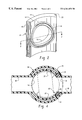
- known barrel type rotary water valves as shown in FIG. 1 have employed a face seal formed of resilient sealing material such as elastomer having a curved face 1 configured to conform to the surface of the rotary valving member; and, on the opposite or face 2 configured to seal about the rim of one of the valve port.
- a tubular extension 3 is provided from the inner periphery of the seal, which extension inserted into the valve port 4 in the valve body 5 for locating the seal thereabout.
- This arrangement has proven to be relatively costly in manufacturing the seal and difficult to assemble in mass production for the water valve.
- the variation in seal dimensions resulting from molding operations for the seal has proven excessive with the result that a widely varying amount of seal compression has occurred in the valves in mass production; and, leakage and sealing problems have resulted.
- the present invention provides a face seal for a rotary barrel type valve, particularly suitable for controlling flow of hot water to a vehicle passenger compartment heater core.
- the seal is formed of resiliently compressible material with an arcuate configuration having a concave inner face with a rib formed about the flow passage passing through the seal to the convex outer face.
- the seal is preferably formed in a rectangular plan form with oppositely disposed spaced parallel edges which have flanges formed thereon which facilitate sliding assembly and retention in a valve body grooved to receive the seals.
- the rib formed about the flow passage on the inner face of the seal member provides adequate material to ensure a sufficient amount of localized compression of the seal between the rotary valving member and the valve body upon assembly in the valve so as to provide reliable sealing during movement of the valve member and thereby minimizes the occurrence of leakage.
- FIG. 1 is a cross-section of a valve body showing the face seal assembly for the rotary valve member as embodied in the prior art
- FIG. 2 is an axonometric or perspective view of the face seal of the present invention
- FIG. 3 is a cross-section taken along section indicating lines 3 — 3 of FIG. 2;
- FIG. 4 is a cross-section of a rotary valve employing the seal of the present invention.
- the seal of the present invention is indicated generally at 10 and has an arcuate configuration when viewed edgewise with a concave inner face 12 and a convex outer face 14 disposed in spaced parallel arrangement with the inner face; and, seal 10 has a generally rectangular plan form when viewed in a direction normal to the inner face 12 as illustrated in FIG. 2.
- a flow passage or aperture 16 is formed through the seal 10 from the inner face to the outer face, which aperture has an annular rib 18 formed therearound and which extends radially inwardly inner face 12 to provide a sealing rim about the aperture 16 on the inner face of the seal.
- the rib 18 is configured to extend radially inwardly from inner face 12 by an amount sufficient to provide adequate compression of the rib 18 in a radial direction upon assembly with the rotary valving member (see FIG. 4) in the valve body 30 ; and, rib 18 is dimensioned to provide the desired amount of radial compression irrespective of the variance of the dimensions of the valving chamber and valving member permissible within the allowable manufacturing tolerances of the individual ports.
- the central region of the outer convex face 14 of the seal has a reduced thickness portion formed by a flattened surface extending through a chordal distance denoted by the reference character “d” in FIG. 3 .
- the portion of the seal within the distance d thus has increased flexibility in the radial direction and may be deformed more readily upon assembly of the seal in the valving chamber structure of a valve body denoted generally at 30 and thereby permits relief of the seal member in the central region to accommodate some compression in a circumferential direction as will hereinafter be described.
- the circumferentially opposite sides or edges of the seal have provided thereon a flange or axially extending rib denoted respectively by reference numerals 20 , 22 which serve to engage correspondingly configured spaced parallel grooves provided in the valving chamber structure of the body of the valve as denoted respectively by reference numerals 24 , 26 in FIG. 4 .
- the seal 10 is configured to be inserted in an axial direction in a bore 28 formed in valve body 30 with respectively inlet and outlet ports 32 , 34 formed in the valve body and which communicate respectively with inlet and outlet passages 36 , 38 .
- a cross ported barrel type rotary valving member 38 is disposed in the bore 28 and rotatable therein with the outer surface of the barrel 38 sealing against the annular rib 18 to as to permit control of flow between ports 32 and 34 .
- the seal upon insertion of the seal into the grooves 24 , 26 a slight amount of circumferential compression is provided to secure the seal firmly in the valve body; and, this is accommodated by the reduced thickness portion of the seal in the central region as described above with regard to the chordal distanced.
- the seal has a radial thickness nominally of about 3.8 mm and the rib 18 extends radially inwardly from the inner face 12 by an amount of about 0.6 mm. It will be understood however, that the dimensions of the seal may be varied to accommodate the configuration of the valve body in which the seal is employed.
- the face seal is formed of elastomeric material, and in the present practice ethylene propylenedimonomer (EPDM) material has been found particularly satisfactory; however, it will be understood that other suitable resiliently flexible sealing materials may be employed if desired, such as wax impregnated EPDM or elastomeric material having a relatively thin coating of polytetrafluoroethylene (PTFE) material.
- EPDM ethylene propylenedimonomer
- PTFE polytetrafluoroethylene
- the present invention thus provides a relatively low cost, easy to install and reliable face seal for a rotary valve, particularly a barrel type rotary valve and has found particular application in motor vehicle passenger compartment heater core water valves.
Abstract
A cylindrically curved rectangular face seal is provided for a cross-ported barrel type rotary valve member. The seal has a central flow orifice therethrough with an annular raised rib formed about the orifice and extending in a radial direction from the concave inner face of the seal. The opposite edges of the seal extending in an axial direction each have a notch or rib thereon for axial sliding engagement in grooves provided in the valve body. The annular rib about the orifice accommodates dimensional variation in the valve parts to ensure a rotary sliding seal on the rotary valve member.
Description
The present invention relates to seals for valves and particularly to seals for a valve having a rotatable valving member which controls flow in a valving chamber between an inlet and an outlet in response to rotation of the valving member. Valves of this type have proven to be generally relatively low in manufacturing costs and particularly suitable for controlling flow of hot water to a passenger compartment heater core in motor vehicles. Heretofore, such heater core valves have been provided with a rotatable butterfly or throttle plate type valving member which has been manually actuated; and, more recently, moved by a servo actuator such as a vacuum motor or electric servo motor. However, butterfly type water valves provide nearly full flow when the butterfly plate is rotated from a closed position to only about one-fourth of its fully open position; and, therefore accurate flow control by the servo actuator is quite difficult to achieve.
With the advent of microcomputer based electronic controllers, it has been desired to provide an all electrical control system for motor vehicle passenger compartment climate control systems. Where the vehicle passenger compartment climate control system utilizes stacked cores, i.e., has the heater core and the passenger compartment air conditioner heat exchanger or evaporator disposed fluidically in series in the blower air discharge plenum, it has become necessary to provide linear response for the valve controlling flow of hot water (engine coolant) to the heater core in order for the system controller to operate the system without executing extremes of heating and cooling to regulate cabin temperature. Thus, it has been desired to provide a heater core valve which provides nearly linear flow or proportional flow control with respect to movement of the valve member. Furthermore, in order to minimize the operating force required to move the valve member, particularly where the valve is to be electrically operated, it has been desired to employ a rotary valve. It has therefore been desired to provide a rotary valving mechanism which provides nearly proportional control of the flow with respect to rotation of the valving member.
It has been proposed to use a barrel or rotary spool type valve which is transversely or cross ported to control the flow between a valve inlet port and a valve outlet port provided in the valving chamber. However, problems have been encountered in designing and manufacturing such a rotary barrel type water valve inasmuch as providing a rotary sliding or face seal about the cross port with respect to the valving chamber has proven extremely difficult and has resulted in a relatively low number of cycles or operations in the service life of a heater core water valve. Tolerances in manufacturing have created a wide variation in the percentage of compression of the seal required to maintain sealing integrity; and, problems of foundry core sand from the engine water jacket passages have caused seal scoring and leakage of the seal. In numerous cases this has resulted in the inability to shut off flow to the passenger department heater core and effectively disabling of the cooling mode of system operation. This has been particularly troublesome where the heater core is fluidically in tandem or series with the air conditioning system refrigerant evaporator coil provided in the forced air plenum of the vehicle passenger compartment climate control system.
Heretofore, known barrel type rotary water valves as shown in FIG. 1 have employed a face seal formed of resilient sealing material such as elastomer having a curved face 1 configured to conform to the surface of the rotary valving member; and, on the opposite or face 2 configured to seal about the rim of one of the valve port. A tubular extension 3 is provided from the inner periphery of the seal, which extension inserted into the valve port 4 in the valve body 5 for locating the seal thereabout. This arrangement has proven to be relatively costly in manufacturing the seal and difficult to assemble in mass production for the water valve. Furthermore, the variation in seal dimensions resulting from molding operations for the seal has proven excessive with the result that a widely varying amount of seal compression has occurred in the valves in mass production; and, leakage and sealing problems have resulted.
Thus, it has long been desired to provide a face seal for a rotary valve which is low in manufacturing costs and can accommodate a wide variation of valve port dimensions and provides a consistent and satisfactory amount of compression of the seal during valve assembly without requiring special operations or tooling for valve assembly.
The present invention provides a face seal for a rotary barrel type valve, particularly suitable for controlling flow of hot water to a vehicle passenger compartment heater core. The seal is formed of resiliently compressible material with an arcuate configuration having a concave inner face with a rib formed about the flow passage passing through the seal to the convex outer face. The seal is preferably formed in a rectangular plan form with oppositely disposed spaced parallel edges which have flanges formed thereon which facilitate sliding assembly and retention in a valve body grooved to receive the seals. The rib formed about the flow passage on the inner face of the seal member provides adequate material to ensure a sufficient amount of localized compression of the seal between the rotary valving member and the valve body upon assembly in the valve so as to provide reliable sealing during movement of the valve member and thereby minimizes the occurrence of leakage.
FIG. 1 is a cross-section of a valve body showing the face seal assembly for the rotary valve member as embodied in the prior art;
FIG. 2 is an axonometric or perspective view of the face seal of the present invention;
FIG. 3 is a cross-section taken along section indicating lines 3—3 of FIG. 2; and,
FIG. 4 is a cross-section of a rotary valve employing the seal of the present invention.
Referring to FIGS. 2 and 3, the seal of the present invention is indicated generally at 10 and has an arcuate configuration when viewed edgewise with a concave inner face 12 and a convex outer face 14 disposed in spaced parallel arrangement with the inner face; and, seal 10 has a generally rectangular plan form when viewed in a direction normal to the inner face 12 as illustrated in FIG. 2. A flow passage or aperture 16 is formed through the seal 10 from the inner face to the outer face, which aperture has an annular rib 18 formed therearound and which extends radially inwardly inner face 12 to provide a sealing rim about the aperture 16 on the inner face of the seal. In the present practice of the invention, the rib 18 is configured to extend radially inwardly from inner face 12 by an amount sufficient to provide adequate compression of the rib 18 in a radial direction upon assembly with the rotary valving member (see FIG. 4) in the valve body 30; and, rib 18 is dimensioned to provide the desired amount of radial compression irrespective of the variance of the dimensions of the valving chamber and valving member permissible within the allowable manufacturing tolerances of the individual ports.
The central region of the outer convex face 14 of the seal has a reduced thickness portion formed by a flattened surface extending through a chordal distance denoted by the reference character “d” in FIG. 3. The portion of the seal within the distance d thus has increased flexibility in the radial direction and may be deformed more readily upon assembly of the seal in the valving chamber structure of a valve body denoted generally at 30 and thereby permits relief of the seal member in the central region to accommodate some compression in a circumferential direction as will hereinafter be described.
The circumferentially opposite sides or edges of the seal have provided thereon a flange or axially extending rib denoted respectively by reference numerals 20, 22 which serve to engage correspondingly configured spaced parallel grooves provided in the valving chamber structure of the body of the valve as denoted respectively by reference numerals 24, 26 in FIG. 4.
Referring to FIGS. 2 and 4, the seal 10 is configured to be inserted in an axial direction in a bore 28 formed in valve body 30 with respectively inlet and outlet ports 32, 34 formed in the valve body and which communicate respectively with inlet and outlet passages 36, 38. A cross ported barrel type rotary valving member 38 is disposed in the bore 28 and rotatable therein with the outer surface of the barrel 38 sealing against the annular rib 18 to as to permit control of flow between ports 32 and 34.
It will be understood that upon insertion of the seal into the grooves 24, 26 a slight amount of circumferential compression is provided to secure the seal firmly in the valve body; and, this is accommodated by the reduced thickness portion of the seal in the central region as described above with regard to the chordal distanced. In the presently preferred practice of the invention, the seal has a radial thickness nominally of about 3.8 mm and the rib 18 extends radially inwardly from the inner face 12 by an amount of about 0.6 mm. It will be understood however, that the dimensions of the seal may be varied to accommodate the configuration of the valve body in which the seal is employed. The face seal is formed of elastomeric material, and in the present practice ethylene propylenedimonomer (EPDM) material has been found particularly satisfactory; however, it will be understood that other suitable resiliently flexible sealing materials may be employed if desired, such as wax impregnated EPDM or elastomeric material having a relatively thin coating of polytetrafluoroethylene (PTFE) material.
The present invention thus provides a relatively low cost, easy to install and reliable face seal for a rotary valve, particularly a barrel type rotary valve and has found particular application in motor vehicle passenger compartment heater core water valves.
Although the invention has hereinabove been described with respect to the illustrated embodiments, it will be understood that the invention is capable of modification and variation and is limited only by the following claims.
Claims (9)
1. A face seal for a rotary valve comprising: a unitary member of resiliently flexible material having a generally partial cylindrical configuration with an aperture therethrough, with a pair of spaced generally parallel margins and generally parallel radially inner and outer faces, said aperture having a rib formed therearound on said radially inner face, wherein said parallel margins includes surfaces adapted for axial sliding engagement with corresponding portions of a valving chamber and wherein said rib is adapted for compression and sliding sealing on a rotary valve member.
2. The seal defined in claim 1 , wherein said parallel margins each include a an axially extending rib therein for sliding engagement in correspondingly configured surfaces in a valve body.
3. The seal defined in claim 1 , wherein said unitary member is formed of elastomeric material.
4. The seal defined in claim 1 , wherein said unitary member is formed of ethylene propylenedimonomer (EPDM) material.
5. The seal defined in claim 1 , wherein said unitary member is formed of wax impregnated EPDM material.
6. The seal defined in claim 1 , wherein said unitary member is formed of elastomeric material having a relatively thin coating of polytetrafluoroethylene (PTFE).
7. The seal defined in claim 1 , wherein said partial cylindrical shape has a portion thereof with a reduced thickness between said inner and outer faces.
8. The seal defined in claim 1 , wherein said unitary member has a portion thereof equidistant from said parallel margins configured for increased flexibility.
9. The seal defined in claim 1 , wherein said rib has an annular groove formed therein for forming a double lip sealing surface about said aperture.
Priority Applications (4)
| Application Number | Priority Date | Filing Date | Title |
|---|---|---|---|
| US09/435,978 US6361051B1 (en) | 1999-11-08 | 1999-11-08 | Face seal for barrel type water valve |
| CA002324659A CA2324659C (en) | 1999-11-08 | 2000-10-30 | Face seal for barrel type water valve |
| EP00123919A EP1098118A3 (en) | 1999-11-08 | 2000-11-03 | Seal for plug valve |
| MXPA00010942A MXPA00010942A (en) | 1999-11-08 | 2000-11-08 | Seal for plug valve. |
Applications Claiming Priority (1)
| Application Number | Priority Date | Filing Date | Title |
|---|---|---|---|
| US09/435,978 US6361051B1 (en) | 1999-11-08 | 1999-11-08 | Face seal for barrel type water valve |
Publications (1)
| Publication Number | Publication Date |
|---|---|
| US6361051B1 true US6361051B1 (en) | 2002-03-26 |
Family
ID=23730608
Family Applications (1)
| Application Number | Title | Priority Date | Filing Date |
|---|---|---|---|
| US09/435,978 Expired - Fee Related US6361051B1 (en) | 1999-11-08 | 1999-11-08 | Face seal for barrel type water valve |
Country Status (4)
| Country | Link |
|---|---|
| US (1) | US6361051B1 (en) |
| EP (1) | EP1098118A3 (en) |
| CA (1) | CA2324659C (en) |
| MX (1) | MXPA00010942A (en) |
Cited By (21)
| Publication number | Priority date | Publication date | Assignee | Title |
|---|---|---|---|---|
| US20060202149A1 (en) * | 2003-11-14 | 2006-09-14 | Muddiman G R | Cylindrical plug valve |
| US7255129B2 (en) | 2005-02-01 | 2007-08-14 | Pentair Water Pool And Spa, Inc. | Valve with elbow joint diverter |
| US20090008934A1 (en) * | 2007-07-03 | 2009-01-08 | S.P.M. Flow Control, Inc. | Swivel joint with uniform ball bearing requirements |
| US20110160835A1 (en) * | 2005-11-02 | 2011-06-30 | Biosensors International Group, Ltd. | Indirect-release electrolytic implant delivery systems |
| USD707332S1 (en) * | 2013-03-15 | 2014-06-17 | S.P.M. Flow Control, Inc. | Seal assembly |
| USD707797S1 (en) * | 2013-03-15 | 2014-06-24 | S.P.M. Flow Control, Inc. | Seal segment |
| US8978695B2 (en) | 2009-04-20 | 2015-03-17 | S.P.M. Flow Control, Inc. | Flowline flapper valve |
| US8998168B2 (en) | 2009-06-03 | 2015-04-07 | S.P.M. Flow Control, Inc. | Plug valve indicator |
| US9103448B2 (en) | 2012-08-16 | 2015-08-11 | S.P.M. Flow Control, Inc. | Plug valve having preloaded seal segments |
| US9273543B2 (en) | 2012-08-17 | 2016-03-01 | S.P.M. Flow Control, Inc. | Automated relief valve control system and method |
| US9322243B2 (en) | 2012-08-17 | 2016-04-26 | S.P.M. Flow Control, Inc. | Automated relief valve control system and method |
| US9568138B2 (en) | 2013-07-01 | 2017-02-14 | S.P.M. Flow Control, Inc. | Manifold assembly |
| US9649436B2 (en) | 2011-09-21 | 2017-05-16 | Bayer Healthcare Llc | Assembly method for a fluid pump device for a continuous multi-fluid delivery system |
| US10267424B2 (en) | 2016-02-12 | 2019-04-23 | Mueller International, Llc | Butterfly valve seat with seat cover |
| EP3553355A1 (en) * | 2018-04-12 | 2019-10-16 | Continental Automotive GmbH | Seal and fluid control valve |
| US10507319B2 (en) | 2015-01-09 | 2019-12-17 | Bayer Healthcare Llc | Multiple fluid delivery system with multi-use disposable set and features thereof |
| US10557576B2 (en) | 2015-06-15 | 2020-02-11 | S.P.M. Flow Control, Inc. | Full-root-radius-threaded wing nut having increased wall thickness |
| US10677365B2 (en) | 2015-09-04 | 2020-06-09 | S.P.M. Flow Control, Inc. | Pressure relief valve assembly and methods |
| CN111677903A (en) * | 2020-06-22 | 2020-09-18 | 何浩南 | PE ball valve |
| WO2021013340A1 (en) * | 2019-07-23 | 2021-01-28 | Pierburg Gmbh | Rotary slide valve for a cooling circuit |
| US11686394B2 (en) | 2021-01-28 | 2023-06-27 | Mueller International, Llc | Bonded seat valve |
Families Citing this family (2)
| Publication number | Priority date | Publication date | Assignee | Title |
|---|---|---|---|---|
| US6854710B2 (en) | 2001-10-25 | 2005-02-15 | Illinois Tool Works Inc. | Valve assembly |
| WO2023169669A1 (en) * | 2022-03-09 | 2023-09-14 | Pierburg Pump Technology Gmbh | Rotary slide valve for a motor vehicle cooling circuit |
Citations (16)
| Publication number | Priority date | Publication date | Assignee | Title |
|---|---|---|---|---|
| US2310583A (en) | 1941-04-03 | 1943-02-09 | Reed Roller Bit Co | Valve |
| US3552716A (en) * | 1969-06-03 | 1971-01-05 | Walworth Co | Plug valve with a flexible port plate |
| US3698687A (en) | 1970-07-17 | 1972-10-17 | Ktm Ind Inc | Rotatory valve having one-piece seat construction |
| US3726314A (en) * | 1971-08-18 | 1973-04-10 | A Moen | Valve seal construction |
| US3840048A (en) * | 1972-07-03 | 1974-10-08 | Stanadyne Inc | Seal construction |
| US3916950A (en) | 1972-11-03 | 1975-11-04 | Stanadyne Inc | Seal construction |
| US4266754A (en) * | 1977-04-01 | 1981-05-12 | Asahi Yukizai Kogyo Co., Ltd. | Butterfly valve assembly |
| US4305419A (en) * | 1979-02-12 | 1981-12-15 | Stanadyne, Inc. | Self-cleaning water faucet valve construction |
| US4469121A (en) * | 1982-01-18 | 1984-09-04 | Stanadyne, Inc. | Cycle valves |
| US4478388A (en) * | 1982-11-01 | 1984-10-23 | Xomox Corporation | Plug valve with removable lip insert means |
| US4494730A (en) * | 1982-11-01 | 1985-01-22 | Xomox Corporation | Plug valve with improved plastic sleeve |
| US4628962A (en) * | 1986-01-06 | 1986-12-16 | United States Brass Corporation | Tub-shower diverter valve |
| US4815704A (en) | 1987-07-21 | 1989-03-28 | Metallpraecis Berchem & Schaberg Gesellschaft Fur Metallformgebung M.B.H. | Ball valve |
| US4881570A (en) * | 1986-09-12 | 1989-11-21 | Fluhs Drehtechnik Gmbh | Seal for valves |
| US4883253A (en) | 1982-12-16 | 1989-11-28 | Sekisui Kagaku Kogyo Kabushiki Kaisha | Ball valve and methods of fabrication |
| US5901964A (en) * | 1997-02-06 | 1999-05-11 | John R. Williams | Seal for a longitudinally movable drillstring component |
-
1999
- 1999-11-08 US US09/435,978 patent/US6361051B1/en not_active Expired - Fee Related
-
2000
- 2000-10-30 CA CA002324659A patent/CA2324659C/en not_active Expired - Fee Related
- 2000-11-03 EP EP00123919A patent/EP1098118A3/en not_active Withdrawn
- 2000-11-08 MX MXPA00010942A patent/MXPA00010942A/en active IP Right Grant
Patent Citations (16)
| Publication number | Priority date | Publication date | Assignee | Title |
|---|---|---|---|---|
| US2310583A (en) | 1941-04-03 | 1943-02-09 | Reed Roller Bit Co | Valve |
| US3552716A (en) * | 1969-06-03 | 1971-01-05 | Walworth Co | Plug valve with a flexible port plate |
| US3698687A (en) | 1970-07-17 | 1972-10-17 | Ktm Ind Inc | Rotatory valve having one-piece seat construction |
| US3726314A (en) * | 1971-08-18 | 1973-04-10 | A Moen | Valve seal construction |
| US3840048A (en) * | 1972-07-03 | 1974-10-08 | Stanadyne Inc | Seal construction |
| US3916950A (en) | 1972-11-03 | 1975-11-04 | Stanadyne Inc | Seal construction |
| US4266754A (en) * | 1977-04-01 | 1981-05-12 | Asahi Yukizai Kogyo Co., Ltd. | Butterfly valve assembly |
| US4305419A (en) * | 1979-02-12 | 1981-12-15 | Stanadyne, Inc. | Self-cleaning water faucet valve construction |
| US4469121A (en) * | 1982-01-18 | 1984-09-04 | Stanadyne, Inc. | Cycle valves |
| US4478388A (en) * | 1982-11-01 | 1984-10-23 | Xomox Corporation | Plug valve with removable lip insert means |
| US4494730A (en) * | 1982-11-01 | 1985-01-22 | Xomox Corporation | Plug valve with improved plastic sleeve |
| US4883253A (en) | 1982-12-16 | 1989-11-28 | Sekisui Kagaku Kogyo Kabushiki Kaisha | Ball valve and methods of fabrication |
| US4628962A (en) * | 1986-01-06 | 1986-12-16 | United States Brass Corporation | Tub-shower diverter valve |
| US4881570A (en) * | 1986-09-12 | 1989-11-21 | Fluhs Drehtechnik Gmbh | Seal for valves |
| US4815704A (en) | 1987-07-21 | 1989-03-28 | Metallpraecis Berchem & Schaberg Gesellschaft Fur Metallformgebung M.B.H. | Ball valve |
| US5901964A (en) * | 1997-02-06 | 1999-05-11 | John R. Williams | Seal for a longitudinally movable drillstring component |
Cited By (34)
| Publication number | Priority date | Publication date | Assignee | Title |
|---|---|---|---|---|
| US20060202149A1 (en) * | 2003-11-14 | 2006-09-14 | Muddiman G R | Cylindrical plug valve |
| US7255129B2 (en) | 2005-02-01 | 2007-08-14 | Pentair Water Pool And Spa, Inc. | Valve with elbow joint diverter |
| US20110160835A1 (en) * | 2005-11-02 | 2011-06-30 | Biosensors International Group, Ltd. | Indirect-release electrolytic implant delivery systems |
| US20090008934A1 (en) * | 2007-07-03 | 2009-01-08 | S.P.M. Flow Control, Inc. | Swivel joint with uniform ball bearing requirements |
| US9964245B2 (en) | 2007-07-03 | 2018-05-08 | S.P.M. Flow Control, Inc. | Swivel joint with uniform ball bearing requirements |
| US8870233B2 (en) | 2007-07-03 | 2014-10-28 | S.P.M. Flow Control, Inc. | Swivel joint with uniform ball bearing requirements |
| US8978695B2 (en) | 2009-04-20 | 2015-03-17 | S.P.M. Flow Control, Inc. | Flowline flapper valve |
| US8998168B2 (en) | 2009-06-03 | 2015-04-07 | S.P.M. Flow Control, Inc. | Plug valve indicator |
| US9700672B2 (en) | 2011-09-21 | 2017-07-11 | Bayer Healthcare Llc | Continuous multi-fluid pump device, drive and actuating system and method |
| US9649436B2 (en) | 2011-09-21 | 2017-05-16 | Bayer Healthcare Llc | Assembly method for a fluid pump device for a continuous multi-fluid delivery system |
| US9103448B2 (en) | 2012-08-16 | 2015-08-11 | S.P.M. Flow Control, Inc. | Plug valve having preloaded seal segments |
| US9638337B2 (en) | 2012-08-16 | 2017-05-02 | S.P.M. Flow Control, Inc. | Plug valve having preloaded seal segments |
| US9273543B2 (en) | 2012-08-17 | 2016-03-01 | S.P.M. Flow Control, Inc. | Automated relief valve control system and method |
| US9322243B2 (en) | 2012-08-17 | 2016-04-26 | S.P.M. Flow Control, Inc. | Automated relief valve control system and method |
| US9857807B2 (en) | 2012-08-17 | 2018-01-02 | S.P.M. Flow Control, Inc. | Automated relief valve control system and method |
| USD734434S1 (en) * | 2013-03-15 | 2015-07-14 | S.P.M. Flow Control, Inc. | Seal assembly |
| USD707797S1 (en) * | 2013-03-15 | 2014-06-24 | S.P.M. Flow Control, Inc. | Seal segment |
| USD707332S1 (en) * | 2013-03-15 | 2014-06-17 | S.P.M. Flow Control, Inc. | Seal assembly |
| US9568138B2 (en) | 2013-07-01 | 2017-02-14 | S.P.M. Flow Control, Inc. | Manifold assembly |
| USD873860S1 (en) | 2013-07-01 | 2020-01-28 | S.P.M. Flow Control, Inc. | Mounting bracket for manifold assembly |
| US10738928B2 (en) | 2013-07-01 | 2020-08-11 | S.P.M. Flow Control, Inc. | Manifold assembly |
| US11491318B2 (en) | 2015-01-09 | 2022-11-08 | Bayer Healthcare Llc | Multiple fluid delivery system with multi-use disposable set and features thereof |
| US10507319B2 (en) | 2015-01-09 | 2019-12-17 | Bayer Healthcare Llc | Multiple fluid delivery system with multi-use disposable set and features thereof |
| US11519530B2 (en) | 2015-06-15 | 2022-12-06 | Spm Oil & Gas Inc. | Full-root-radius-threaded wing nut having increased wall thickness |
| US10557576B2 (en) | 2015-06-15 | 2020-02-11 | S.P.M. Flow Control, Inc. | Full-root-radius-threaded wing nut having increased wall thickness |
| US10677365B2 (en) | 2015-09-04 | 2020-06-09 | S.P.M. Flow Control, Inc. | Pressure relief valve assembly and methods |
| US10267424B2 (en) | 2016-02-12 | 2019-04-23 | Mueller International, Llc | Butterfly valve seat with seat cover |
| WO2019197321A1 (en) * | 2018-04-12 | 2019-10-17 | Cpt Group Gmbh | Seal and fluid valve |
| EP3553355A1 (en) * | 2018-04-12 | 2019-10-16 | Continental Automotive GmbH | Seal and fluid control valve |
| US11635016B2 (en) | 2018-04-12 | 2023-04-25 | Vitesco Technologies GmbH | Seal and fluid valve |
| WO2021013340A1 (en) * | 2019-07-23 | 2021-01-28 | Pierburg Gmbh | Rotary slide valve for a cooling circuit |
| CN111677903B (en) * | 2020-06-22 | 2021-12-03 | 玉环孙氏暖通设备有限公司 | PE ball valve |
| CN111677903A (en) * | 2020-06-22 | 2020-09-18 | 何浩南 | PE ball valve |
| US11686394B2 (en) | 2021-01-28 | 2023-06-27 | Mueller International, Llc | Bonded seat valve |
Also Published As
| Publication number | Publication date |
|---|---|
| EP1098118A3 (en) | 2001-05-16 |
| MXPA00010942A (en) | 2002-05-23 |
| CA2324659C (en) | 2006-09-19 |
| CA2324659A1 (en) | 2001-05-08 |
| EP1098118A2 (en) | 2001-05-09 |
Similar Documents
| Publication | Publication Date | Title |
|---|---|---|
| US6361051B1 (en) | Face seal for barrel type water valve | |
| US6315267B1 (en) | Electrically controlled servo operated engine coolant valve | |
| KR101291484B1 (en) | Control valve with sealing segment for fluid circulation circuit | |
| US7111643B2 (en) | Flow characterization in a flowpath | |
| US3675681A (en) | Three-position butterfly valve | |
| US5531248A (en) | Butterfly valve | |
| US20150188157A1 (en) | 3-way valve for fuel cell vehicle | |
| US5009392A (en) | Rotary air valve | |
| US7367544B2 (en) | Apparatus and method for replacing existing actuator zone valves in an HVAC system with a ball valve | |
| US11560952B2 (en) | Variable cylinder wall for seals on plug valve | |
| US4280682A (en) | Cam actuated butterfly valve | |
| EP1156243B1 (en) | Flow control valve | |
| US6588442B2 (en) | Servo operated rotary valve with emergency bypass and method of making same | |
| US7913389B2 (en) | Method of making a flapper valve assembly | |
| US5374032A (en) | Butterfly valve assembly | |
| US20240003430A1 (en) | Valve device | |
| US20240003458A1 (en) | Valve device | |
| US5263893A (en) | Air distribution housing with integrally formed internal bearing pins and its method of manufacture | |
| KR19990023244A (en) | Electrically actuated and compressed air operated valve assembly | |
| CN116249852A (en) | Control valve | |
| CN117441076A (en) | Rotary disk valve | |
| CN115380182A (en) | Hard sealing element for plug valve on cylindrical wall | |
| US4273157A (en) | Three way butterfly valve | |
| JP4126824B2 (en) | Flow control valve | |
| US2975763A (en) | Vacuum servo system |
Legal Events
| Date | Code | Title | Description |
|---|---|---|---|
| AS | Assignment |
Owner name: EATON CORPORATION, OHIO Free format text: ASSIGNMENT OF ASSIGNORS INTEREST;ASSIGNOR:BABIN, CHRISTOPHER J.;REEL/FRAME:010382/0894 Effective date: 19991105 |
|
| FEPP | Fee payment procedure |
Free format text: PAYOR NUMBER ASSIGNED (ORIGINAL EVENT CODE: ASPN); ENTITY STATUS OF PATENT OWNER: LARGE ENTITY |
|
| FPAY | Fee payment |
Year of fee payment: 4 |
|
| REMI | Maintenance fee reminder mailed | ||
| LAPS | Lapse for failure to pay maintenance fees | ||
| STCH | Information on status: patent discontinuation |
Free format text: PATENT EXPIRED DUE TO NONPAYMENT OF MAINTENANCE FEES UNDER 37 CFR 1.362 |
|
| FP | Lapsed due to failure to pay maintenance fee |
Effective date: 20100326 |