US6364822B1 - Hero-turbine centrifuge with drainage enhancing baffle devices - Google Patents
Hero-turbine centrifuge with drainage enhancing baffle devices Download PDFInfo
- Publication number
- US6364822B1 US6364822B1 US09/732,276 US73227600A US6364822B1 US 6364822 B1 US6364822 B1 US 6364822B1 US 73227600 A US73227600 A US 73227600A US 6364822 B1 US6364822 B1 US 6364822B1
- Authority
- US
- United States
- Prior art keywords
- base
- fluid
- rotor assembly
- centrifuge
- baffle
- Prior art date
- Legal status (The legal status is an assumption and is not a legal conclusion. Google has not performed a legal analysis and makes no representation as to the accuracy of the status listed.)
- Expired - Lifetime
Links
Images


Classifications
-
- B—PERFORMING OPERATIONS; TRANSPORTING
- B04—CENTRIFUGAL APPARATUS OR MACHINES FOR CARRYING-OUT PHYSICAL OR CHEMICAL PROCESSES
- B04B—CENTRIFUGES
- B04B5/00—Other centrifuges
- B04B5/005—Centrifugal separators or filters for fluid circulation systems, e.g. for lubricant oil circulation systems
-
- B—PERFORMING OPERATIONS; TRANSPORTING
- B04—CENTRIFUGAL APPARATUS OR MACHINES FOR CARRYING-OUT PHYSICAL OR CHEMICAL PROCESSES
- B04B—CENTRIFUGES
- B04B1/00—Centrifuges with rotary bowls provided with solid jackets for separating predominantly liquid mixtures with or without solid particles
- B04B1/04—Centrifuges with rotary bowls provided with solid jackets for separating predominantly liquid mixtures with or without solid particles with inserted separating walls
- B04B1/08—Centrifuges with rotary bowls provided with solid jackets for separating predominantly liquid mixtures with or without solid particles with inserted separating walls of conical shape
Abstract
A cone-stack centrifuge for separating particulate material out of a circulating fluid includes a rotor assembly configured with a hollow rotor hub and is constructed to rotate about an axis by the ejection of the fluid from nozzles in the rotor assembly. The rotor assembly is mounted on a shaft that is attached to the hub of a base. The base further includes a fluid inlet, a passageway connected to the inlet and in fluid communication with the rotor assembly, and fluid outlet. A bearing arrangement is positioned between the rotor hub and the shaft for rotary motion of the rotor assembly about the shaft. The base further includes a baffle for re-directing a swirling flow of fluid out of the base in a radial direction and into the fluid outlet.
Description
The present invention relates generally to the continuous separation of solid particles, such as soot, from a fluid, such as oil, by the use of a centrifugal field. More particularly the present invention relates to the use of a cone (disk) stack centrifuge configuration within a centrifuge assembly with a base that redirects the residual velocity of fluid discharge from the rotor jet nozzles to assist drainage rate and reduce pooling of oil in the centrifuge base.
Diesel engines are designed with relatively sophisticated air and fuel filters (cleaners) in an effort to keep dirt and debris out of the engine. Even with these air and fuel cleaners, dirt and debris, including engine-generated wear debris, will find a way into the lubricating oil of the engine. The result is wear on critical engine components and if this condition is left unsolved or not remedied, engine failure. For this reason, many engines are designed with full flow oil filters that continually clean the oil as it circulates between the lubricant sump and engine parts.
There are a number of design constraints and considerations for such full flow filters, and typically these constraints mean that such filters can only remove those dirt particles that are in the range of 10 microns or larger. While removal of particles of this size may prevent a catastrophic failure, harmful wear will still be caused by smaller particles of dirt that get into and remain in the oil. In order to try and address the concern over small particles, designers have gone to bypass filtering systems which filter a predetermined percentage of the total oil flow. The combination of a full flow filter in conjunction with a bypass filter reduces engine wear to an acceptable level, but not to the desired level. Since bypass filters may be able to trap particles less then approximately 10 microns, the combination of a full flow filter and bypass filter offers a substantial improvement over the use of only a full flow filter.
While centrifuge cleaners can be configured in a variety of ways as represented by the earlier designs of others, one product which is representative of part of the early design evolution is the Spinner II® oil cleaning centrifuge made by Glacier Metal Company Ltd., of Somerset, Ilminister, United Kingdom, and offered by T.F. Hudgins, Incorporated, of Houston, Tex. Various advances and improvements to the Spinner II® product are represented by U.S. Pat. Nos. 5,575,912; 5,637,217; 6,017,300; and 6,019,717 issued to Herman Nov. 19, 1996; Jun. 10, 1997; Jan. 25, 2000; and Feb. 1, 2000, respectively. These four patents are expressly incorporated by reference herein for their entire disclosures.
Hero-turbine centrifuges, as commonly used as bypass separators on diesel engine lube systems, operate by ejecting a high velocity fluid jet from a nozzle, which drives the centrifuge rotor via reaction force. After ejection from the centrifuge rotor, the fluid must be quickly evacuated from the centrifuge base and drained back to the sump. If the fluid begins to pool in the base, a condition known as flooding can occur, whereby the fluid contacts the turbine ends of the centrifuge rotor and dramatically slows down the speed of rotation. In this flooded condition, the centrifuge is rendered useless since it is no longer spinning at the desired speed and separating particulate from the oil. This condition is usually avoided by designing a very large outlet drain and providing enough head space beneath the rotor to allow some pooling to occur without the oil contacting the rotor.
The need therefore exists for a design that reduces the necessary size of outlet drain or reduces the required head space beneath the rotor, thereby allowing more room for rotor sludge capacity. The present invention meets this need in a novel and non-obvious way.
One aspect of the invention described herein is providing a centrifuge base with means for redirecting the residual velocity of fluid discharge from the rotor jet nozzles from a tangential direction to a radial direction in order to assist drainage rate and reduce pooling of oil in the centrifuge base.
One form of the present invention contemplates a centrifuge base with a radially directed gravity drain outlet configured with an outlet baffle oriented to redirect the residual fluid velocity in the radially outward direction of the drain outlet.
Another form of the present invention contemplates a centrifuge housing base having a central bottom drain where the base is equipped with spiral vanes to redirect the residual fluid velocity radially inward toward the drain outlet.
One object of the present invention is to provide a unique centrifuge base that assists the oil drainage rate and reduces pooling of oil in the base.
Further objects, features, and advantages of the present invention will be apparent from the description and drawings contained herein.
FIG. 1 is a front elevational view in full section of a cone-stack centrifuge according to one embodiment of the present invention.
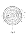
FIG. 2 is a top plan view in full section of the FIG. 1 centrifuge as view along line 2—2 in FIG. 1.
FIG. 3 is a perspective view of the base of a cone-stack centrifuge according to an alternative embodiment of the present invention.
For the purposes of promoting an understanding of the principles of the invention, reference will now be made to the embodiments illustrated in the drawings and specific language will be used to describe the same. It will nevertheless be understood that no limitation of the scope of the invention is thereby intended, such alterations and further modifications in the illustrated device, and such further applications of the principles of the invention as illustrated therein being contemplated as would normally occur to one skilled in the art to which the invention relates.
Referring to FIG. 1, there is illustrated a cone-stack centrifuge 20 according to a preferred embodiment of the present invention. Centrifuge 20 includes as some of its primary components base 21, bell housing 22, shaft 23, and rotor assembly 24 including rotor hub 25, cone-stack 26, tangential flow jet nozzles 27 and 28, bottom plate 29, and centrifuge bowl 30 securely sealed to bottom plate 29. Axially extending through the center of bottom plate 29 and through the interior of centrifuge bowl 30 is hollow rotor hub 25. Rotor hub 25 is bearingly mounted to and supported by shaft 23 by means of upper and lower bearings 34 and 35, respectively.
At the lower region of bottom plate 29 are two tangential flow nozzles 27 and 28. These tangential flow nozzles are symmetrically positioned on opposite sides of the axis of rotor hub 25, and their corresponding flow jet directions 99, as seen in FIG. 2, are opposite one another. As a result, these flow nozzles are able to create the driving force for rotating rotor assembly 24 about shaft 23 within bell housing 22, as is believed to be well known in the art. Spinning of centrifuge 20 can also be accomplished with a single flow nozzle, or with the use of more than two flow nozzles.
The assembly between centrifuge bowl 30 and bottom plate 29 in combination with O-ring 70 creates a sealed enclosure defining an interior volume 73 which contains cone-stack 26. Each cone 74 of cone-stack 26 has a center opening 75 and a plurality of inlet holes disposed around the circumference of the cone adjacent the outer annular edge 77. Typical cones for this application are illustrated and disclosed in U.S. Pat. Nos. 5,575,912 and 5,637,217. The typical flow path for rotor assembly 24 begins with the flow of liquid upwardly through the hollow center 78 of rotor hub 25. The flow through the interior of rotor hub 25 exits out through apertures 79. A flow distribution plate 80 is configured with vanes and used to distribute the existing flow out of hub 25 across the surface of top cone 74 a. The manner in which the liquid (lubricating oil) flows across and through the individual cones 74 of cone-stack 26 is a flow path and flow phenomenon which is well known in the art. This flow path and the high RPM spinning rate of the cone-stack assembly enables the small particles of soot which are carried by the oil to be centrifugally separated out of the oil and held in the centrifuge.
The focus of the present invention is on the design of base 21 which is configured with and defines fluid inlet 82, passageway 83 connected to the inlet, and a fluid outlet that permits the fluid entering base 21 from flow nozzles 27 and 28 to exit base 21. Base 21 further includes base hub 87 and base sidewall 96 defining interior space 95 of base 21. In one embodiment of the present invention, the fluid outlet is radial outlet drain 97 defined by sidewall 96. Shaft 23 which extends through rotor hub 25 is attached to base hub 87 and includes passageway 91 which is in fluid communication with base passageway 83 at one end and with hollow center 78 of rotor hub 25 at the other end.
In operation of centrifuge 20, pressurized fluid enters base 21 through fluid inlet 82 and flows through passageway 83 of base 21. The fluid continues up through base hub 87 and into passageway 91 of shaft 23. The fluid is then delivered to rotor assembly 24 via throttle passageway 93 in shaft 23. The fluid flows through rotor assembly 24 as described above and then exits rotor assembly 24 through tangential flow nozzles 27 and 28 into interior space 95 of base 21.
Since the discharge velocity of exit flow jets 99 from nozzles 27 and 28 is always higher than the counter-rotational velocity of nozzles 27 and 28, a residual velocity component exists in the fluid discharge that is substantially oriented in a tangential direction opposite to the rotor assembly rotation. Illustrated in FIG. 2, this residual velocity causes the liquid in base 21 of the centrifuge to swirl around in a cyclonic fashion. Energy from this residual velocity can be harnessed to assist fluid drainage from base 21 by attaching upstream-directed baffle 98 that scoops the swirling flow off of base sidewall 96 and re-directs the fluid in a radially outward direction into radial outlet drain 97. Baffle 98 is positioned over at least a portion of radial outlet drain 97 and projects in an upstream direction relative to the swirling flow in base 21. Baffle 98 preferably has a first end 98 a attached to bottom surface 94 of base 21 and a second end 98 b attached to sidewall 96 above radial outlet drain 97. In a preferred embodiment, baffle 98 further includes, as best seen in FIG. 2, a first side 98 c projecting into the swirling flow of fluid and a second side 98 d attached to sidewall 96 at a radial location downstream from radial outlet drain 97. As shown in FIG. 2, baffle 98 is oriented for the clockwise rotation of rotor assembly 24 produced by exit flow jets 99 from nozzles 27 and 28. The use of baffle 98 in base 21 of centrifuge 20 is similar in concept to the use of upstream-oriented air-ram inlets on highway trucks to increase the pressure at the air inlet location, thereby improving air flow to the truck engine.
In some cone-stack centrifuges, such as that illustrated in FIG. 3, the fluid outlet in base 121 is preferably central bottom drain 197. In order to assist the drainage of fluid from base 121, vanes 198 are connected to bottom surface 194 of base 121. Vanes 198 are oriented in a direction such that they re-direct the swirling flow near sidewall 196 radially inward toward central bottom drain 197. Additionally or alternatively, vanes 198 may be connected to sidewall 196 of base 121. In a preferred embodiment, vanes 198 are spiral-shaped and cast or molded into base 121. Further, vanes 198 preferably project vertically away from bottom surface 194.
To achieve the desired radial redirection of the fluid flow, the included intercept angle between vane 198 and base sidewall 196 should be less than 90° which corresponds to a straight radial vane. Useful intercept angles range between 10°-80° and preferably range between 0°-45° in order to minimize fluid shock, and the concomitant loss in energy upon impact with the vane at the vane-sidewall interface. A 0° intercept angle can be achieved by employing a generous fillet radius between the vane and sidewall 196 at the point of intersection. Of course, the direction of the spiral, and the associated included intercept angle, must be oriented with respect to the direction of exit flow jets 99. FIG. 3 illustrates the proper orientation of vanes 198 for the counterclockwise rotation of a rotor assembly that creates a swirling flow in the direction of arrow 199.
From the above description, a person of skill in the art will readily appreciate that bases 21 and 121 can be incorporated into any number of designs of self-driven centrifuges. The present invention is therefore, not limited to the design of rotor assembly 24 of cone stack centrifuge 20. In this regard, the rotor assembly could take on various designs provided that it is constructed and arranged to rotate about an axis and that it is adapted to receive a fluid and to discharge at least a portion of that fluid through a tangential flow nozzle, such as nozzles 27 and 28. This discharge of fluid causes the rotor assembly to rotate and simultaneously causes the swirling of fluid in the base. Thus, the incorporation of either base 21 or 121 with such a rotor assembly assists the drainage rate and reduces the pooling of fluid in the base. Alternative rotor assemblies include, for example but without limitation, a take-apart hero turbine without a cone stack, as well as centrifuges in which the vertical cone stack is replaced by a unitary, molded spiral vane module.
While the invention has been illustrated and described in detail in the drawings and foregoing description, the same is to be considered as illustrative and not restrictive in character, it being understood that only the preferred embodiment has been shown and described and that all changes and modifications that come within the spirit of the invention are desired to be protected.
Claims (13)
1. A cone-stack centrifuge for separating particulate material out of a circulating fluid, said centrifuge comprising:
a rotor assembly constructed and arranged to rotate about an axis, said rotor assembly including a cone-stack, a hollow rotor hub, a centrifuge bowl, and a bottom plate assembled to said centrifuge bowl and including at least one tangential flow nozzle for creating an exit flow jet, said exit flow jet causing said rotor assembly to rotate, said rotor hub extending through said centrifuge bowl and through said bottom plate;
a base defining a fluid inlet, a passageway connected to said fluid inlet, a fluid outlet, a base hub, a sidewall, and a bottom surface;
a shaft attached to said base hub and extending through said rotor hub, said shaft having a passageway therein for delivering said fluid from said base passageway to said cone-stack;
a bearing positioned between said rotor hub and said shaft for rotary motion of said rotor assembly about said shaft;
said base having means for re-directing a swirling flow of said fluid in said base in a radial direction into said fluid outlet; and
wherein said fluid outlet is a radial outlet drain in said base sidewall and said means for re-directing said swirling flow is a baffle that urges said swirling flow in a radially outward direction.
2. The apparatus of claim 1 , wherein said baffle projects in an upstream direction relative to said swirling flow.
3. The apparatus of claim 1 , wherein a length of said baffle is attached to said base sidewall at a location downstream from said radial outlet drain.
4. The apparatus of claim 1 , wherein a length of said baffle is attached to said base sidewall above said radial outlet drain.
5. The apparatus of claim 1 , wherein an end of said baffle is attached to said base bottom surface.
6. A cone-stack contrifuge for separating particulate material out of a circulating fluid, said centrifuge comprising:
a rotor assembly constructed and arranged to rotate about an axis, said rotor assembly including a cone-stack, a hollow rotor hub, a centrifuge bowl, and a bottom plate assembled to said centrifuge bowl and including at least one tangential flow nozzle for creating an exit flow jet, said exit flow jet causing said rotor assembly to rotate, said rotor hub extending through said centrifuge bowl and through said bottom plate;
a base defining a fluid inlet, a passageway connected to said fluid inlet, a fluid outlet, a base hub, a sidewall, and a bottom surface;
a shaft attached to said base hub and extending through said rotor hub, said shaft having a passageway therein for delivering said fluid from said base passageway to said cone-stack;
a bearing positioned between said rotor hub and said shaft for rotary motion of said rotor assembly about said shaft;
said base having means for re-directing a swirling flow of said fluid in said base in a radial direction into said fluid outlet; and
wherein said fluid outlet is a central bottom drain and said means for re-directing said swirling flow is at least one vane connected to said base bottom surface to urge said swirling flow in a radially inward direction, wherein said vane is spiral-shaped.
7. A base for a self-driven centrifuge having a rotor assembly constructed and arranged to rotate about an axis and adapted to receive a fluid and to discharge at least a part of the fluid through at least one tangential flow nozzle creating an exit flow jet, the exit flow jet causing rotation of the rotor assembly, said base comprising:
a sidewall;
a bottom surface;
a fluid outlet;
means for re-directing a swirling flow of at least a part of said fluid in said base in a radial direction into said fluid outlet; and
wherein said fluid outlet is a radial outlet drain in said base sidewall and said means for re-directing said swirling flow is a baffle that urges said swirling flow in a radially outward direction.
8. A centrifuge, comprising:
a rotor assembly;
a flow nozzle defined in said rotor assembly to spin said rotor assembly by discharging fluid;
a centrifuge base, said centrifuge base including
a bottom surface,
a sidewall extending from said bottom surface to define an interior space,
a fluid outlet defined in said base, and
a baffle extending into said interior space, said baffle being constructed and arranged to re-direct the fluid discharged from said flow nozzle in a radial direction into said fluid outlet;
wherein said fluid outlet is defined in said sidewall;
wherein said baffle is constructed and arranged to deflect said fluid in a radially outward direction into said fluid outlet; and
wherein said baffle includes
a first end attached to said bottom surface, and
a second end attached to said sidewall above said fluid outlet.
9. The centrifuge of claim 8 , wherein said baffle further includes
a first side projecting into a swirling flow path of said fluid, and
a second side attached to said sidewall downstream from said fluid outlet.
10. The apparatus of claim 8 , wherein said rotor assembly includes a cone-stack.
11. A centrifuge, comprising:
a rotor assembly;
a flow nozzle defined in said rotor assembly to spin said rotor assembly by discharging fluid;
a centrifuge base, said centrifuge base including
a bottom surface,
a sidewall extending from said bottom surface to define an interior space,
a fluid outlet defined in said base, and
a baffle extending into said interior space, said baffle being constructed and arranged to re-direct the fluid discharged from said flow nozzle in a radial direction into said fluid outlet;
wherein said fluid outlet is centrally defined in said bottom surface;
wherein said baffle includes a vane constructed and arranged to deflect said fluid in a radially inward direction into said fluid outlet; and
wherein said vane in includes a spiral vane connected to said sidewall and said bottom surface.
12. The apparatus of claim 11 , wherein an intercept angle formed between said vane and said sidewall is less than ninety degrees.
13. The apparatus of claim 11 , wherein said rotor assembly includes a cone-stack.
Priority Applications (6)
| Application Number | Priority Date | Filing Date | Title |
|---|---|---|---|
| US09/732,276 US6364822B1 (en) | 2000-12-07 | 2000-12-07 | Hero-turbine centrifuge with drainage enhancing baffle devices |
| AU2002227301A AU2002227301A1 (en) | 2000-12-07 | 2001-12-05 | Hero-turbine centrifuge with drainage enhancing baffle devices |
| CNA018222838A CN1487855A (en) | 2000-12-07 | 2001-12-05 | Hero-turbine centrifuge with drainage enhancing baffle devices |
| DE10197016T DE10197016T1 (en) | 2000-12-07 | 2001-12-05 | Hero turbine centrifuge with lead-improving guidance devices |
| GB0315523A GB2386849B (en) | 2000-12-07 | 2001-12-05 | Hero-turbine centrifuge with drainage enhancing baffle devices |
| PCT/US2001/047204 WO2002045864A1 (en) | 2000-12-07 | 2001-12-05 | Hero-turbine centrifuge with drainage enhancing baffle devices |
Applications Claiming Priority (1)
| Application Number | Priority Date | Filing Date | Title |
|---|---|---|---|
| US09/732,276 US6364822B1 (en) | 2000-12-07 | 2000-12-07 | Hero-turbine centrifuge with drainage enhancing baffle devices |
Publications (1)
| Publication Number | Publication Date |
|---|---|
| US6364822B1 true US6364822B1 (en) | 2002-04-02 |
Family
ID=24942900
Family Applications (1)
| Application Number | Title | Priority Date | Filing Date |
|---|---|---|---|
| US09/732,276 Expired - Lifetime US6364822B1 (en) | 2000-12-07 | 2000-12-07 | Hero-turbine centrifuge with drainage enhancing baffle devices |
Country Status (6)
| Country | Link |
|---|---|
| US (1) | US6364822B1 (en) |
| CN (1) | CN1487855A (en) |
| AU (1) | AU2002227301A1 (en) |
| DE (1) | DE10197016T1 (en) |
| GB (1) | GB2386849B (en) |
| WO (1) | WO2002045864A1 (en) |
Cited By (21)
| Publication number | Priority date | Publication date | Assignee | Title |
|---|---|---|---|---|
| US6652439B2 (en) * | 2000-04-04 | 2003-11-25 | Fleetguard, Inc. | Disposable rotor shell with integral molded spiral vanes |
| WO2003101619A1 (en) * | 2002-05-28 | 2003-12-11 | Baker Hughes Incorporated | Centrifugal separator bowl assembly with flow guide |
| WO2004004911A2 (en) * | 2002-07-03 | 2004-01-15 | Gp Handels- & Dienstleistungs Gmbh | Method and device for cleaning and transporting dirty water solutions occurring during cleaning processes |
| US20040157719A1 (en) * | 2003-02-07 | 2004-08-12 | Amirkhanian Hendrik N. | Centrifuge with separate hero turbine |
| US20040214710A1 (en) * | 2003-04-23 | 2004-10-28 | Herman Peter K. | Integral air/oil coalescer for a centrifuge |
| US20050133466A1 (en) * | 2003-12-19 | 2005-06-23 | Honeywell International Inc. | Multi-stage centrifugal debris trap |
| US20080051278A1 (en) * | 2005-05-02 | 2008-02-28 | Hengst Gmbh & Co. Kg | Centrifuge Rotor |
| US7674376B1 (en) | 2005-05-27 | 2010-03-09 | Cummins Filtration Ip Inc. | Centrifuge with integral depth filter |
| US20110011795A1 (en) * | 2009-07-15 | 2011-01-20 | Hoff William D | Fluid pressure driven centrifuge apparatus |
| US20110180051A1 (en) * | 2010-01-27 | 2011-07-28 | Cummins Filtration Ip Inc. | Crankcase Ventilation Inside-Out Flow Rotating Coalescer |
| US20110232245A1 (en) * | 2009-09-30 | 2011-09-29 | Cummins Filtration Ip Inc. | Auxiliary o-ring gland |
| US20130067873A1 (en) * | 2010-04-09 | 2013-03-21 | Alfa Laval Corporate Ab | Centrifugal separator |
| CN103071601A (en) * | 2012-12-27 | 2013-05-01 | 海申机电总厂(象山) | Centrifugal liquid kinetic energy converting device |
| US8893689B2 (en) | 2010-01-27 | 2014-11-25 | Cummins Filtration Ip, Inc. | Crankcase ventilation self-cleaning coalescer with intermittent rotation |
| US8940068B2 (en) | 2010-01-27 | 2015-01-27 | Cummins Filtration Ip Inc. | Magnetically driven rotating separator |
| US20150053603A1 (en) * | 2013-08-23 | 2015-02-26 | Mann+Hummel Gmbh | Filtration Apparatus |
| US8974567B2 (en) | 2010-01-27 | 2015-03-10 | Cummins Filtration Ip Inc. | Rotating coalescer with keyed drive |
| WO2015110360A1 (en) * | 2014-01-22 | 2015-07-30 | Mann+Hummel Gmbh | Self-cleaning centrifugal separator |
| US9194265B2 (en) | 2010-01-27 | 2015-11-24 | Cummins Filtration Ip, Inc. | Rotating separator with housing preventing separated liquid carryover |
| US9545591B2 (en) | 2010-01-27 | 2017-01-17 | Cummins Filtration Ip, Inc. | Rotating separator with housing preventing separated liquid carryover |
| WO2024052752A1 (en) * | 2022-09-05 | 2024-03-14 | Luxnara Yaovaphankul | A cone stack cyclone separator and vacuum cleaner having same |
Families Citing this family (2)
| Publication number | Priority date | Publication date | Assignee | Title |
|---|---|---|---|---|
| US7959546B2 (en) | 2007-01-24 | 2011-06-14 | Honeywell International Inc. | Oil centrifuge for extracting particulates from a continuous flow of fluid |
| DE102012110846A1 (en) * | 2012-11-12 | 2014-05-15 | Gea Mechanical Equipment Gmbh | Separator with direct drive |
Citations (99)
| Publication number | Priority date | Publication date | Assignee | Title |
|---|---|---|---|---|
| US882119A (en) | 1904-05-10 | 1908-03-17 | Empire Cream Separator Company | Liner for centrifugal separators. |
| US955890A (en) | 1909-04-02 | 1910-04-26 | Laval Separator Co De | Centrifugal clarifier and filter. |
| US993791A (en) | 1905-08-19 | 1911-05-30 | Gustaf Oscar Wallenberg | Liner for centrifugal liquid-separators. |
| US1006662A (en) | 1910-10-06 | 1911-10-24 | George L Knowlton | Signal for automobiles or other vehicles. |
| US1038607A (en) | 1910-06-17 | 1912-09-17 | Welcome H Lawson | Centrifugal separator. |
| US1136654A (en) | 1914-03-23 | 1915-04-20 | Waldo E Callane | Centrifugal cream-separator. |
| US1151686A (en) | 1913-11-25 | 1915-08-31 | Carl Alrik Hult | Liner for centrifugal liquid-separators. |
| US1232811A (en) | 1917-04-16 | 1917-07-10 | Vermont Farm Machine Company | Centrifugal cream-separator. |
| US1293114A (en) | 1915-02-03 | 1919-02-04 | Internat Instr Company | Centrifugal filtering-machine. |
| US1422852A (en) | 1922-07-18 | Centrifugal machine | ||
| US1482418A (en) | 1923-07-05 | 1924-02-05 | Ind Products Company | Centrifugal machine |
| US1525016A (en) | 1923-01-10 | 1925-02-03 | James W Weir | Method of manufacturing lubricating oils |
| GB229647A (en) | 1924-02-19 | 1926-02-25 | Separator Ab | Device for securing a proper flow of liquids in purifying centrifugal bowls provided with distributors with double outlets |
| US1784510A (en) | 1928-05-07 | 1930-12-09 | Sharples Specialty Co | Centrifugal apparatus |
| US2031734A (en) | 1933-08-21 | 1936-02-25 | Air Way Electric Appl Corp | Vacuum cleaner |
| US2053856A (en) | 1935-07-26 | 1936-09-08 | Russell A Weidenbacker | Edge type oil filter |
| US2087778A (en) | 1936-01-07 | 1937-07-20 | Kone Ja Silta O Y Maskin Och B | Centrifugal machine for filtering purposes |
| US2129751A (en) | 1934-05-25 | 1938-09-13 | Standard Oil Dev Co | Operation of a centrifuge for separating the petroleum oil from sulphuric acid |
| US2302381A (en) | 1940-04-12 | 1942-11-17 | Sharples Corp | Centrifugal separator |
| US2305469A (en) | 1940-06-03 | 1942-12-15 | Laval Separator Co De | Disk liner for centrifugal bowls |
| US2321144A (en) * | 1940-02-19 | 1943-06-08 | Sharples Corp | Centrifugal purification of liquids |
| US2335420A (en) * | 1941-04-26 | 1943-11-30 | Sharples Corp | Oil purifying system for vehicles |
| US2485390A (en) | 1945-09-25 | 1949-10-18 | Gen Electric | Centrifugal fluid purifier |
| US2578485A (en) | 1947-05-05 | 1951-12-11 | Nyrop Aage | Centrifugal separation |
| US2665060A (en) | 1950-07-15 | 1954-01-05 | Int Harvester Co | Power washing centrifugal separator with indentations along the inner peripheral edges of the separating disks |
| US2725190A (en) | 1954-04-19 | 1955-11-29 | Int Harvester Co | Cream separator disk assembly |
| US2735614A (en) | 1956-02-21 | Hubmann | ||
| US2738923A (en) | 1954-09-21 | 1956-03-20 | Int Harvester Co | Compression disk assembly for power washing cream separators |
| US2752090A (en) | 1952-08-29 | 1956-06-26 | Robert S Mode | Centrifugal separators |
| US2755017A (en) | 1952-08-30 | 1956-07-17 | Robert S Mode | Centrifugal separators |
| GB812047A (en) | 1957-01-22 | 1959-04-15 | Separator Ab | Centrifugal bowl, with pre-separating chamber, for separating sludge-containing liquids |
| DE1097370B (en) * | 1959-11-10 | 1961-01-12 | Mann & Hummel Filter | Centrifugal cleaner for liquids, especially lubricating oils |
| US2973896A (en) | 1956-01-19 | 1961-03-07 | Dorr Oliver Inc | Centrifuge apparatus |
| FR1275728A (en) | 1959-12-08 | 1961-11-10 | Separator Ab | Centrifugal separator designed for the separation of liquids containing flocculating sludge |
| SU145089A1 (en) * | 1961-02-14 | 1962-01-01 | Ю.А. Кудинов | Fuel centrifuge |
| US3080109A (en) | 1958-11-13 | 1963-03-05 | Dorr Oliver Inc | Centrifuge machine |
| US3187998A (en) | 1964-03-31 | 1965-06-08 | Vernon D Jarvis | Centrifugal extractor |
| US3273324A (en) | 1962-05-28 | 1966-09-20 | United Aircraft Corp | Turbine driven rotary liquid-gas separation system |
| GB1089355A (en) | 1965-09-22 | 1967-11-01 | Glacier Co Ltd | Centrifugal fluid cleaners |
| US3430853A (en) | 1966-10-07 | 1969-03-04 | Samuel A Kirk | Turbine centrifuge |
| SU362643A1 (en) | 1969-03-07 | 1972-12-30 | ALL-UNION iii - -.'-;> &'';;•; "• .1; •:.?> &! Ay | |
| US3784092A (en) | 1971-04-27 | 1974-01-08 | Glacier Metal Co Ltd | Centrifugal separator |
| US3858793A (en) | 1973-02-28 | 1975-01-07 | Donaldson Co Inc | Cartridge centrifuge |
| US3879294A (en) | 1972-05-04 | 1975-04-22 | Sperry Rand Corp | Fluid operated contaminant trap |
| US3990631A (en) | 1974-11-04 | 1976-11-09 | Schall Wallace J | Centrifugal scraper and separator apparatus |
| SU564884A1 (en) | 1974-12-27 | 1977-07-15 | Московский Трижды Ордена Ленина И Ордена Трудового Красного Знамени Автомобильный Завод Им.И.А.Лихачева | Centrifuge for purifying oil in internal-combustion engine |
| SU578110A1 (en) * | 1976-03-16 | 1977-10-30 | Предприятие П/Я В-2302 | Reactive liquid-clarifying centrifuge |
| US4067494A (en) | 1977-01-03 | 1978-01-10 | Dorr-Oliver Incorporated | Nozzle type centrifugal machine with improved slurry pumping chambers |
| GB1507742A (en) | 1976-06-25 | 1978-04-19 | Glacier Metal Co Ltd | Centrifugal filters |
| US4106689A (en) | 1977-04-06 | 1978-08-15 | The Weatherhead Company | Disposable centrifugal separator |
| SU633609A1 (en) | 1976-02-11 | 1978-11-25 | Предприятие П/Я Р-6197 | Liquid-purifying centrifuge |
| US4165032A (en) | 1977-06-17 | 1979-08-21 | Dana Corporation | Disposable centrifugal separator with baffle means |
| CA1079699A (en) | 1977-04-04 | 1980-06-17 | Glacier Metal Company Limited (The) | Disposable centrifugal separator |
| US4221323A (en) | 1978-12-07 | 1980-09-09 | The Glacier Metal Company Limited | Centrifugal filter with external service indicator |
| US4230581A (en) | 1976-03-24 | 1980-10-28 | The Glacier Metal Company, Limited | Centrifugal separators |
| GB2049494A (en) | 1979-04-12 | 1980-12-31 | Glacier Metal Co Ltd | Centrifugal separator |
| US4262841A (en) | 1977-10-26 | 1981-04-21 | Berber Viktor A | Truncated conical disc separator |
| US4284504A (en) * | 1979-10-09 | 1981-08-18 | Hastings Manufacturing Company | Centrifugal spin-on filter or separator and method of making and assembling the same |
| US4288030A (en) | 1979-04-12 | 1981-09-08 | The Glacier Metal Company Limited | Centrifugal separator |
| SU869822A1 (en) | 1980-01-07 | 1981-10-07 | Рижский Дизелестроительный Завод | Centrifugal machine for cleaning liquids |
| US4325825A (en) | 1979-04-26 | 1982-04-20 | Hoechst Aktiengesellschaft | Separator |
| US4346009A (en) | 1979-10-09 | 1982-08-24 | Hastings Manufacturing Co. | Centrifugal spin-on filter or separator |
| US4400167A (en) | 1980-04-11 | 1983-08-23 | The Glacier Metal Company Limited | Centrifugal separator |
| US4427407A (en) | 1980-12-04 | 1984-01-24 | Klockner-Humboldt-Deutz Ag | Centrifugal bowl separator |
| US4431540A (en) | 1982-09-24 | 1984-02-14 | Tadeusz Budzich | Centrifugal filter separator |
| US4460352A (en) | 1982-01-22 | 1984-07-17 | Westfalia Separator Ag | Centrifuge drum for clarifying and/or separating liquids |
| US4492631A (en) * | 1982-01-19 | 1985-01-08 | Ae Plc | Centrifugal separator |
| US4498898A (en) | 1982-04-16 | 1985-02-12 | Ae Plc | Centrifugal separator |
| US4508530A (en) | 1982-08-27 | 1985-04-02 | Bertin & Cie | Energy recuperation centrifuge |
| SU1158242A1 (en) * | 1983-07-13 | 1985-05-30 | Ленинградский Ордена Трудового Красного Знамени Институт Водного Транспорта | Reactive centrifuge for cleaning oil |
| US4557831A (en) * | 1984-04-12 | 1985-12-10 | Mack Trucks, Inc. | Centrifugal filter assembly |
| US4615315A (en) | 1984-05-04 | 1986-10-07 | Ae Plc | Oil cleaning assemblies for engines |
| US4698053A (en) | 1985-07-05 | 1987-10-06 | Alfa-Laval Separation Ab | Centrifugal separator |
| US4731545A (en) | 1986-03-14 | 1988-03-15 | Desai & Lerner | Portable self-contained power conversion unit |
| US4787975A (en) | 1985-02-26 | 1988-11-29 | Ae Plc | Disposable cartridges for centrifugal separators |
| US4861329A (en) | 1987-12-07 | 1989-08-29 | Alfa-Laval Separation Ab | Centrifugal separator |
| US4915682A (en) | 1987-10-13 | 1990-04-10 | Alfa-Laval Separation Ab | Centrifugal separator |
| US4950130A (en) | 1988-10-06 | 1990-08-21 | Sulzer Brothers Limited | Pelton turbine |
| US4961724A (en) | 1988-09-30 | 1990-10-09 | Occam Marine Technologies Ltd. | Low speed particle concentrators |
| US5045049A (en) | 1988-10-17 | 1991-09-03 | Alfa-Laval Separation Ab | Centrifugal separator |
| US5052996A (en) | 1988-10-17 | 1991-10-01 | Alfa-Laval Separation Ab | Centrifugal separator |
| US5096581A (en) | 1986-07-23 | 1992-03-17 | Ae Plc | Centrifugal oil filter |
| US5169065A (en) | 1990-06-15 | 1992-12-08 | Naylor Industrial Services | Method and apparatus for water jet cutting including improved nozzle |
| US5213260A (en) | 1991-07-03 | 1993-05-25 | Steven Tonkinson | Nozzle for producing laminar flow |
| US5342279A (en) | 1992-08-18 | 1994-08-30 | Alfa Laval Separation Inc. | Decanter centrifuge having dual motor drive |
| US5354255A (en) | 1992-12-17 | 1994-10-11 | Alfa Laval Separation Inc. | Decanter centrifuge with conveyor capable of high speed and higher flow rates |
| US5362292A (en) | 1990-02-15 | 1994-11-08 | Alfa-Laval Separation Ab | Centrifugal separator |
| US5374234A (en) | 1990-03-13 | 1994-12-20 | Alfa-Laval Separation A/S | Decanter centrifuge with energy dissipating inlet |
| US5575912A (en) * | 1995-01-25 | 1996-11-19 | Fleetguard, Inc. | Self-driven, cone-stack type centrifuge |
| US5637217A (en) * | 1995-01-25 | 1997-06-10 | Fleetguard, Inc. | Self-driven, cone-stack type centrifuge |
| WO1997031180A1 (en) * | 1996-02-20 | 1997-08-28 | Filterwerk Mann+Hummel Gmbh | Separator |
| GB2311022A (en) | 1994-12-22 | 1997-09-17 | Komatsu Mfg Co Ltd | Centrifugal separating filter |
| US5674392A (en) | 1994-10-19 | 1997-10-07 | Moatti Filtration S.A. | Treatment assembly for treating a fluid by filtering and centrifuging |
| US5707519A (en) | 1996-11-27 | 1998-01-13 | Caterpillar Inc. | Centrifugal oil filter with particle retention |
| WO1998011994A1 (en) | 1996-09-17 | 1998-03-26 | Federal-Mogul Engineering Limited | Centrifugal separation apparatus |
| US6017300A (en) * | 1998-08-19 | 2000-01-25 | Fleetguard, Inc. | High performance soot removing centrifuge with impulse turbine |
| US6019717A (en) * | 1998-08-19 | 2000-02-01 | Fleetguard, Inc. | Nozzle inlet enhancement for a high speed turbine-driven centrifuge |
| WO2000044502A1 (en) | 1999-01-27 | 2000-08-03 | Alfa Laval Ab | An outlet of a centrifugal separator having a reaction driven rotor |
| US6183407B1 (en) * | 1998-04-02 | 2001-02-06 | Alfa Laval Ab | Centrifugal separator having axially-extending, angled separation discs |
-
2000
- 2000-12-07 US US09/732,276 patent/US6364822B1/en not_active Expired - Lifetime
-
2001
- 2001-12-05 WO PCT/US2001/047204 patent/WO2002045864A1/en not_active Application Discontinuation
- 2001-12-05 DE DE10197016T patent/DE10197016T1/en not_active Withdrawn
- 2001-12-05 GB GB0315523A patent/GB2386849B/en not_active Expired - Fee Related
- 2001-12-05 AU AU2002227301A patent/AU2002227301A1/en not_active Abandoned
- 2001-12-05 CN CNA018222838A patent/CN1487855A/en active Pending
Patent Citations (104)
| Publication number | Priority date | Publication date | Assignee | Title |
|---|---|---|---|---|
| US1422852A (en) | 1922-07-18 | Centrifugal machine | ||
| US2735614A (en) | 1956-02-21 | Hubmann | ||
| US882119A (en) | 1904-05-10 | 1908-03-17 | Empire Cream Separator Company | Liner for centrifugal separators. |
| US993791A (en) | 1905-08-19 | 1911-05-30 | Gustaf Oscar Wallenberg | Liner for centrifugal liquid-separators. |
| US955890A (en) | 1909-04-02 | 1910-04-26 | Laval Separator Co De | Centrifugal clarifier and filter. |
| US1038607A (en) | 1910-06-17 | 1912-09-17 | Welcome H Lawson | Centrifugal separator. |
| US1006662A (en) | 1910-10-06 | 1911-10-24 | George L Knowlton | Signal for automobiles or other vehicles. |
| US1151686A (en) | 1913-11-25 | 1915-08-31 | Carl Alrik Hult | Liner for centrifugal liquid-separators. |
| US1136654A (en) | 1914-03-23 | 1915-04-20 | Waldo E Callane | Centrifugal cream-separator. |
| US1293114A (en) | 1915-02-03 | 1919-02-04 | Internat Instr Company | Centrifugal filtering-machine. |
| US1232811A (en) | 1917-04-16 | 1917-07-10 | Vermont Farm Machine Company | Centrifugal cream-separator. |
| US1525016A (en) | 1923-01-10 | 1925-02-03 | James W Weir | Method of manufacturing lubricating oils |
| US1482418A (en) | 1923-07-05 | 1924-02-05 | Ind Products Company | Centrifugal machine |
| GB229647A (en) | 1924-02-19 | 1926-02-25 | Separator Ab | Device for securing a proper flow of liquids in purifying centrifugal bowls provided with distributors with double outlets |
| US1784510A (en) | 1928-05-07 | 1930-12-09 | Sharples Specialty Co | Centrifugal apparatus |
| US2031734A (en) | 1933-08-21 | 1936-02-25 | Air Way Electric Appl Corp | Vacuum cleaner |
| US2129751A (en) | 1934-05-25 | 1938-09-13 | Standard Oil Dev Co | Operation of a centrifuge for separating the petroleum oil from sulphuric acid |
| US2053856A (en) | 1935-07-26 | 1936-09-08 | Russell A Weidenbacker | Edge type oil filter |
| US2087778A (en) | 1936-01-07 | 1937-07-20 | Kone Ja Silta O Y Maskin Och B | Centrifugal machine for filtering purposes |
| US2321144A (en) * | 1940-02-19 | 1943-06-08 | Sharples Corp | Centrifugal purification of liquids |
| US2302381A (en) | 1940-04-12 | 1942-11-17 | Sharples Corp | Centrifugal separator |
| US2305469A (en) | 1940-06-03 | 1942-12-15 | Laval Separator Co De | Disk liner for centrifugal bowls |
| US2335420A (en) * | 1941-04-26 | 1943-11-30 | Sharples Corp | Oil purifying system for vehicles |
| US2485390A (en) | 1945-09-25 | 1949-10-18 | Gen Electric | Centrifugal fluid purifier |
| US2578485A (en) | 1947-05-05 | 1951-12-11 | Nyrop Aage | Centrifugal separation |
| US2665060A (en) | 1950-07-15 | 1954-01-05 | Int Harvester Co | Power washing centrifugal separator with indentations along the inner peripheral edges of the separating disks |
| US2752090A (en) | 1952-08-29 | 1956-06-26 | Robert S Mode | Centrifugal separators |
| US2755017A (en) | 1952-08-30 | 1956-07-17 | Robert S Mode | Centrifugal separators |
| US2725190A (en) | 1954-04-19 | 1955-11-29 | Int Harvester Co | Cream separator disk assembly |
| US2738923A (en) | 1954-09-21 | 1956-03-20 | Int Harvester Co | Compression disk assembly for power washing cream separators |
| US2973896A (en) | 1956-01-19 | 1961-03-07 | Dorr Oliver Inc | Centrifuge apparatus |
| GB812047A (en) | 1957-01-22 | 1959-04-15 | Separator Ab | Centrifugal bowl, with pre-separating chamber, for separating sludge-containing liquids |
| US3036759A (en) | 1957-01-22 | 1962-05-29 | Separator Ab | Centrifugal bowl for separating sludge-containing liquids |
| US3080109A (en) | 1958-11-13 | 1963-03-05 | Dorr Oliver Inc | Centrifuge machine |
| DE1097370B (en) * | 1959-11-10 | 1961-01-12 | Mann & Hummel Filter | Centrifugal cleaner for liquids, especially lubricating oils |
| FR1275728A (en) | 1959-12-08 | 1961-11-10 | Separator Ab | Centrifugal separator designed for the separation of liquids containing flocculating sludge |
| SU145089A1 (en) * | 1961-02-14 | 1962-01-01 | Ю.А. Кудинов | Fuel centrifuge |
| US3273324A (en) | 1962-05-28 | 1966-09-20 | United Aircraft Corp | Turbine driven rotary liquid-gas separation system |
| US3187998A (en) | 1964-03-31 | 1965-06-08 | Vernon D Jarvis | Centrifugal extractor |
| US3432091A (en) | 1965-09-22 | 1969-03-11 | Glacier Metal Co Ltd | Centrifugal fluid cleaners |
| GB1089355A (en) | 1965-09-22 | 1967-11-01 | Glacier Co Ltd | Centrifugal fluid cleaners |
| US3430853A (en) | 1966-10-07 | 1969-03-04 | Samuel A Kirk | Turbine centrifuge |
| SU362643A1 (en) | 1969-03-07 | 1972-12-30 | ALL-UNION iii - -.'-;> &'';;•; "• .1; •:.?> &! Ay | |
| US3784092A (en) | 1971-04-27 | 1974-01-08 | Glacier Metal Co Ltd | Centrifugal separator |
| US3879294A (en) | 1972-05-04 | 1975-04-22 | Sperry Rand Corp | Fluid operated contaminant trap |
| US3858793A (en) | 1973-02-28 | 1975-01-07 | Donaldson Co Inc | Cartridge centrifuge |
| US3990631A (en) | 1974-11-04 | 1976-11-09 | Schall Wallace J | Centrifugal scraper and separator apparatus |
| SU564884A1 (en) | 1974-12-27 | 1977-07-15 | Московский Трижды Ордена Ленина И Ордена Трудового Красного Знамени Автомобильный Завод Им.И.А.Лихачева | Centrifuge for purifying oil in internal-combustion engine |
| SU633609A1 (en) | 1976-02-11 | 1978-11-25 | Предприятие П/Я Р-6197 | Liquid-purifying centrifuge |
| SU578110A1 (en) * | 1976-03-16 | 1977-10-30 | Предприятие П/Я В-2302 | Reactive liquid-clarifying centrifuge |
| US4230581A (en) | 1976-03-24 | 1980-10-28 | The Glacier Metal Company, Limited | Centrifugal separators |
| GB1507742A (en) | 1976-06-25 | 1978-04-19 | Glacier Metal Co Ltd | Centrifugal filters |
| US4067494A (en) | 1977-01-03 | 1978-01-10 | Dorr-Oliver Incorporated | Nozzle type centrifugal machine with improved slurry pumping chambers |
| CA1079699A (en) | 1977-04-04 | 1980-06-17 | Glacier Metal Company Limited (The) | Disposable centrifugal separator |
| US4106689A (en) | 1977-04-06 | 1978-08-15 | The Weatherhead Company | Disposable centrifugal separator |
| US4165032A (en) | 1977-06-17 | 1979-08-21 | Dana Corporation | Disposable centrifugal separator with baffle means |
| US4262841A (en) | 1977-10-26 | 1981-04-21 | Berber Viktor A | Truncated conical disc separator |
| US4221323A (en) | 1978-12-07 | 1980-09-09 | The Glacier Metal Company Limited | Centrifugal filter with external service indicator |
| GB2049494A (en) | 1979-04-12 | 1980-12-31 | Glacier Metal Co Ltd | Centrifugal separator |
| US4288030A (en) | 1979-04-12 | 1981-09-08 | The Glacier Metal Company Limited | Centrifugal separator |
| US4325825A (en) | 1979-04-26 | 1982-04-20 | Hoechst Aktiengesellschaft | Separator |
| US4284504A (en) * | 1979-10-09 | 1981-08-18 | Hastings Manufacturing Company | Centrifugal spin-on filter or separator and method of making and assembling the same |
| US4346009A (en) | 1979-10-09 | 1982-08-24 | Hastings Manufacturing Co. | Centrifugal spin-on filter or separator |
| SU869822A1 (en) | 1980-01-07 | 1981-10-07 | Рижский Дизелестроительный Завод | Centrifugal machine for cleaning liquids |
| US4400167A (en) | 1980-04-11 | 1983-08-23 | The Glacier Metal Company Limited | Centrifugal separator |
| US4427407A (en) | 1980-12-04 | 1984-01-24 | Klockner-Humboldt-Deutz Ag | Centrifugal bowl separator |
| US4492631A (en) * | 1982-01-19 | 1985-01-08 | Ae Plc | Centrifugal separator |
| US4460352A (en) | 1982-01-22 | 1984-07-17 | Westfalia Separator Ag | Centrifuge drum for clarifying and/or separating liquids |
| US4498898A (en) | 1982-04-16 | 1985-02-12 | Ae Plc | Centrifugal separator |
| US4508530A (en) | 1982-08-27 | 1985-04-02 | Bertin & Cie | Energy recuperation centrifuge |
| US4431540A (en) | 1982-09-24 | 1984-02-14 | Tadeusz Budzich | Centrifugal filter separator |
| SU1158242A1 (en) * | 1983-07-13 | 1985-05-30 | Ленинградский Ордена Трудового Красного Знамени Институт Водного Транспорта | Reactive centrifuge for cleaning oil |
| US4557831A (en) * | 1984-04-12 | 1985-12-10 | Mack Trucks, Inc. | Centrifugal filter assembly |
| US4615315A (en) | 1984-05-04 | 1986-10-07 | Ae Plc | Oil cleaning assemblies for engines |
| US4787975A (en) | 1985-02-26 | 1988-11-29 | Ae Plc | Disposable cartridges for centrifugal separators |
| US4698053A (en) | 1985-07-05 | 1987-10-06 | Alfa-Laval Separation Ab | Centrifugal separator |
| US4731545A (en) | 1986-03-14 | 1988-03-15 | Desai & Lerner | Portable self-contained power conversion unit |
| US5096581A (en) | 1986-07-23 | 1992-03-17 | Ae Plc | Centrifugal oil filter |
| US4915682A (en) | 1987-10-13 | 1990-04-10 | Alfa-Laval Separation Ab | Centrifugal separator |
| US4861329A (en) | 1987-12-07 | 1989-08-29 | Alfa-Laval Separation Ab | Centrifugal separator |
| US4961724A (en) | 1988-09-30 | 1990-10-09 | Occam Marine Technologies Ltd. | Low speed particle concentrators |
| US4950130A (en) | 1988-10-06 | 1990-08-21 | Sulzer Brothers Limited | Pelton turbine |
| US5045049A (en) | 1988-10-17 | 1991-09-03 | Alfa-Laval Separation Ab | Centrifugal separator |
| US5052996A (en) | 1988-10-17 | 1991-10-01 | Alfa-Laval Separation Ab | Centrifugal separator |
| US5362292A (en) | 1990-02-15 | 1994-11-08 | Alfa-Laval Separation Ab | Centrifugal separator |
| US5374234A (en) | 1990-03-13 | 1994-12-20 | Alfa-Laval Separation A/S | Decanter centrifuge with energy dissipating inlet |
| US5169065A (en) | 1990-06-15 | 1992-12-08 | Naylor Industrial Services | Method and apparatus for water jet cutting including improved nozzle |
| US5213260A (en) | 1991-07-03 | 1993-05-25 | Steven Tonkinson | Nozzle for producing laminar flow |
| US5342279A (en) | 1992-08-18 | 1994-08-30 | Alfa Laval Separation Inc. | Decanter centrifuge having dual motor drive |
| US5354255A (en) | 1992-12-17 | 1994-10-11 | Alfa Laval Separation Inc. | Decanter centrifuge with conveyor capable of high speed and higher flow rates |
| US5674392A (en) | 1994-10-19 | 1997-10-07 | Moatti Filtration S.A. | Treatment assembly for treating a fluid by filtering and centrifuging |
| US5779618A (en) | 1994-12-22 | 1998-07-14 | Komatsu Ltd. | Centrifugal separating filter |
| GB2311022A (en) | 1994-12-22 | 1997-09-17 | Komatsu Mfg Co Ltd | Centrifugal separating filter |
| US5637217A (en) * | 1995-01-25 | 1997-06-10 | Fleetguard, Inc. | Self-driven, cone-stack type centrifuge |
| US5575912A (en) * | 1995-01-25 | 1996-11-19 | Fleetguard, Inc. | Self-driven, cone-stack type centrifuge |
| US5795477A (en) | 1995-01-25 | 1998-08-18 | Fleetguard, Inc. | Self-driven, cone-stack type centrifuge |
| WO1997031180A1 (en) * | 1996-02-20 | 1997-08-28 | Filterwerk Mann+Hummel Gmbh | Separator |
| WO1998011994A1 (en) | 1996-09-17 | 1998-03-26 | Federal-Mogul Engineering Limited | Centrifugal separation apparatus |
| US6196962B1 (en) | 1996-09-17 | 2001-03-06 | Federal-Mogul Engineering Limited | Centrifugal separator with vortex disruption vanes |
| US5707519A (en) | 1996-11-27 | 1998-01-13 | Caterpillar Inc. | Centrifugal oil filter with particle retention |
| US6183407B1 (en) * | 1998-04-02 | 2001-02-06 | Alfa Laval Ab | Centrifugal separator having axially-extending, angled separation discs |
| US6017300A (en) * | 1998-08-19 | 2000-01-25 | Fleetguard, Inc. | High performance soot removing centrifuge with impulse turbine |
| US6019717A (en) * | 1998-08-19 | 2000-02-01 | Fleetguard, Inc. | Nozzle inlet enhancement for a high speed turbine-driven centrifuge |
| WO2000044502A1 (en) | 1999-01-27 | 2000-08-03 | Alfa Laval Ab | An outlet of a centrifugal separator having a reaction driven rotor |
Non-Patent Citations (5)
| Title |
|---|
| "Theory of Separation", Alfa Laval Separation AB, pp. 1-8. |
| SAE Paper No. 971631, "Soot and Wear in Heavy Duty Diesel Engines", Robert Mainwaring, International Spring Fuels & Lubricants Meeting, Dearborn, Michigan, May 5-8, 1997. |
| Spinner II(R) product brochure, T.G. Hudgins, Incorporated, 1985. |
| Spinner II® product brochure, T.G. Hudgins, Incorporated, 1985. |
| Theodore De Loggio and Alan Letki, "New Directions in Centrifuging", Chemical Engineering, pp. 70-76, Jan., 1994. |
Cited By (40)
| Publication number | Priority date | Publication date | Assignee | Title |
|---|---|---|---|---|
| US6652439B2 (en) * | 2000-04-04 | 2003-11-25 | Fleetguard, Inc. | Disposable rotor shell with integral molded spiral vanes |
| WO2003101619A1 (en) * | 2002-05-28 | 2003-12-11 | Baker Hughes Incorporated | Centrifugal separator bowl assembly with flow guide |
| WO2004004911A2 (en) * | 2002-07-03 | 2004-01-15 | Gp Handels- & Dienstleistungs Gmbh | Method and device for cleaning and transporting dirty water solutions occurring during cleaning processes |
| WO2004004911A3 (en) * | 2002-07-03 | 2004-04-08 | Gp Handels & Dienstleistungs G | Method and device for cleaning and transporting dirty water solutions occurring during cleaning processes |
| US6929596B2 (en) | 2003-02-07 | 2005-08-16 | Fleetguard, Inc. | Centrifuge with separate hero turbine |
| US20040157719A1 (en) * | 2003-02-07 | 2004-08-12 | Amirkhanian Hendrik N. | Centrifuge with separate hero turbine |
| US7235177B2 (en) | 2003-04-23 | 2007-06-26 | Fleetguard, Inc. | Integral air/oil coalescer for a centrifuge |
| US20040214710A1 (en) * | 2003-04-23 | 2004-10-28 | Herman Peter K. | Integral air/oil coalescer for a centrifuge |
| DE102004019057B4 (en) * | 2003-04-23 | 2007-07-05 | Fleetguard, Inc., Nashville | Integral air / oil coalescer for one centrifuge |
| US20050133466A1 (en) * | 2003-12-19 | 2005-06-23 | Honeywell International Inc. | Multi-stage centrifugal debris trap |
| US7175771B2 (en) | 2003-12-19 | 2007-02-13 | Honeywell International, Inc. | Multi-stage centrifugal debris trap |
| US20080051278A1 (en) * | 2005-05-02 | 2008-02-28 | Hengst Gmbh & Co. Kg | Centrifuge Rotor |
| US7396325B2 (en) | 2005-05-02 | 2008-07-08 | Hengst Gmbh & Co. Kg | Centrifuge rotor |
| US7674376B1 (en) | 2005-05-27 | 2010-03-09 | Cummins Filtration Ip Inc. | Centrifuge with integral depth filter |
| US20110011795A1 (en) * | 2009-07-15 | 2011-01-20 | Hoff William D | Fluid pressure driven centrifuge apparatus |
| US8449640B2 (en) | 2009-09-30 | 2013-05-28 | Cummins Filtration Ip Inc. | Auxiliary O-ring gland |
| US20110232245A1 (en) * | 2009-09-30 | 2011-09-29 | Cummins Filtration Ip Inc. | Auxiliary o-ring gland |
| US9194265B2 (en) | 2010-01-27 | 2015-11-24 | Cummins Filtration Ip, Inc. | Rotating separator with housing preventing separated liquid carryover |
| US9574469B2 (en) | 2010-01-27 | 2017-02-21 | Cummins Filtration Ip, Inc | Crankcase ventilation self-cleaning coalescer with intermittent rotation |
| US20110180052A1 (en) * | 2010-01-27 | 2011-07-28 | Cummins Filtration Ip Inc. | Closed Crankcase Ventilation System |
| US20110180051A1 (en) * | 2010-01-27 | 2011-07-28 | Cummins Filtration Ip Inc. | Crankcase Ventilation Inside-Out Flow Rotating Coalescer |
| US8794222B2 (en) * | 2010-01-27 | 2014-08-05 | Cummins Filtration Ip, Inc. | Crankcase ventilation inside-out flow rotating coalescer |
| US8807097B2 (en) | 2010-01-27 | 2014-08-19 | Cummins Filtration Ip Inc. | Closed crankcase ventilation system |
| US8893689B2 (en) | 2010-01-27 | 2014-11-25 | Cummins Filtration Ip, Inc. | Crankcase ventilation self-cleaning coalescer with intermittent rotation |
| US8940068B2 (en) | 2010-01-27 | 2015-01-27 | Cummins Filtration Ip Inc. | Magnetically driven rotating separator |
| US10913023B2 (en) | 2010-01-27 | 2021-02-09 | Cummins Filtration Ip, Inc | Rotating separator with housing preventing separated liquid carryover |
| US9885265B2 (en) | 2010-01-27 | 2018-02-06 | Cummins Filtration Ip Inc. | Crankcase ventilation inside-out flow rotating coalescer |
| US9802146B2 (en) | 2010-01-27 | 2017-10-31 | Cummins Filtration Ip, Inc. | Rotating separator with housing preventing separated liquid carryover |
| US9545591B2 (en) | 2010-01-27 | 2017-01-17 | Cummins Filtration Ip, Inc. | Rotating separator with housing preventing separated liquid carryover |
| US8974567B2 (en) | 2010-01-27 | 2015-03-10 | Cummins Filtration Ip Inc. | Rotating coalescer with keyed drive |
| US9512755B2 (en) * | 2010-04-09 | 2016-12-06 | Alfa Laval Corporate Ab | Centrifugal separator |
| US20130067873A1 (en) * | 2010-04-09 | 2013-03-21 | Alfa Laval Corporate Ab | Centrifugal separator |
| CN103071601A (en) * | 2012-12-27 | 2013-05-01 | 海申机电总厂(象山) | Centrifugal liquid kinetic energy converting device |
| US9474993B2 (en) * | 2013-08-23 | 2016-10-25 | Mann+Hummel Gmbh | Filtration apparatus |
| US20150053603A1 (en) * | 2013-08-23 | 2015-02-26 | Mann+Hummel Gmbh | Filtration Apparatus |
| CN105916590A (en) * | 2014-01-22 | 2016-08-31 | 曼·胡默尔有限公司 | Self-cleaning centrifugal separator |
| US10350614B2 (en) | 2014-01-22 | 2019-07-16 | Mann+Hummel Gmbh | Self-cleaning centrifugal separator |
| CN105916590B (en) * | 2014-01-22 | 2019-10-22 | 曼·胡默尔有限公司 | Automatically cleaning whizzer |
| WO2015110360A1 (en) * | 2014-01-22 | 2015-07-30 | Mann+Hummel Gmbh | Self-cleaning centrifugal separator |
| WO2024052752A1 (en) * | 2022-09-05 | 2024-03-14 | Luxnara Yaovaphankul | A cone stack cyclone separator and vacuum cleaner having same |
Also Published As
| Publication number | Publication date |
|---|---|
| GB2386849B (en) | 2005-03-23 |
| GB0315523D0 (en) | 2003-08-06 |
| AU2002227301A1 (en) | 2002-06-18 |
| WO2002045864A8 (en) | 2002-09-19 |
| GB2386849A (en) | 2003-10-01 |
| CN1487855A (en) | 2004-04-07 |
| DE10197016T1 (en) | 2003-10-30 |
| WO2002045864A1 (en) | 2002-06-13 |
Similar Documents
| Publication | Publication Date | Title |
|---|---|---|
| US6364822B1 (en) | Hero-turbine centrifuge with drainage enhancing baffle devices | |
| EP1008391B1 (en) | A cone-stack centrifuge | |
| US6017300A (en) | High performance soot removing centrifuge with impulse turbine | |
| JP4716640B2 (en) | Self-driven centrifuge with vane module | |
| EP1993702B1 (en) | Centrifugal separator | |
| EP0806985B1 (en) | Self-driven, cone-stack type centrifuge | |
| US10543442B2 (en) | Multiple stage rotating coalescer devices | |
| US5575912A (en) | Self-driven, cone-stack type centrifuge | |
| US6652439B2 (en) | Disposable rotor shell with integral molded spiral vanes | |
| US5713826A (en) | Vertical basket centrifuge with feed acceleration and a removable liner | |
| CN107921346A (en) | The rotation coalescing element of liquid discharge outlet and gas vent with orientation | |
| JP4516260B2 (en) | Centrifuge module with spiral wing | |
| WO2008111909A1 (en) | A particle separator | |
| EP1287895B1 (en) | Free jet centrifuge rotor with internal flow bypass | |
| US20020045526A1 (en) | Molded spiral vane and liner component for a centrifuge | |
| CN108348928B (en) | Separator | |
| EP1142644B1 (en) | Self-driven centrifuge with separation vane module | |
| CN115450729B (en) | Centrifugal oil-gas separator and engine system |
Legal Events
| Date | Code | Title | Description |
|---|---|---|---|
| AS | Assignment |
Owner name: FLEETGUARD, INC., TENNESSEE Free format text: ASSIGNMENT OF ASSIGNORS INTEREST;ASSIGNORS:HERMAN, PETER K.;SOUTH, KEVIN;REEL/FRAME:011362/0762 Effective date: 20001205 |
|
| STCF | Information on status: patent grant |
Free format text: PATENTED CASE |
|
| FPAY | Fee payment |
Year of fee payment: 4 |
|
| FPAY | Fee payment |
Year of fee payment: 8 |
|
| FPAY | Fee payment |
Year of fee payment: 12 |