US6381063B1 - Long band optical amplifier - Google Patents
Long band optical amplifier Download PDFInfo
- Publication number
- US6381063B1 US6381063B1 US09/526,892 US52689200A US6381063B1 US 6381063 B1 US6381063 B1 US 6381063B1 US 52689200 A US52689200 A US 52689200A US 6381063 B1 US6381063 B1 US 6381063B1
- Authority
- US
- United States
- Prior art keywords
- pump
- gain medium
- optical
- optical amplifier
- amplifier according
- Prior art date
- Legal status (The legal status is an assumption and is not a legal conclusion. Google has not performed a legal analysis and makes no representation as to the accuracy of the status listed.)
- Expired - Lifetime
Links
Images


Classifications
-
- H—ELECTRICITY
- H01—ELECTRIC ELEMENTS
- H01S—DEVICES USING THE PROCESS OF LIGHT AMPLIFICATION BY STIMULATED EMISSION OF RADIATION [LASER] TO AMPLIFY OR GENERATE LIGHT; DEVICES USING STIMULATED EMISSION OF ELECTROMAGNETIC RADIATION IN WAVE RANGES OTHER THAN OPTICAL
- H01S3/00—Lasers, i.e. devices using stimulated emission of electromagnetic radiation in the infrared, visible or ultraviolet wave range
- H01S3/05—Construction or shape of optical resonators; Accommodation of active medium therein; Shape of active medium
- H01S3/06—Construction or shape of active medium
- H01S3/063—Waveguide lasers, i.e. whereby the dimensions of the waveguide are of the order of the light wavelength
- H01S3/067—Fibre lasers
- H01S3/06754—Fibre amplifiers
- H01S3/06758—Tandem amplifiers
-
- H—ELECTRICITY
- H01—ELECTRIC ELEMENTS
- H01S—DEVICES USING THE PROCESS OF LIGHT AMPLIFICATION BY STIMULATED EMISSION OF RADIATION [LASER] TO AMPLIFY OR GENERATE LIGHT; DEVICES USING STIMULATED EMISSION OF ELECTROMAGNETIC RADIATION IN WAVE RANGES OTHER THAN OPTICAL
- H01S2301/00—Functional characteristics
- H01S2301/02—ASE (amplified spontaneous emission), noise; Reduction thereof
-
- H—ELECTRICITY
- H01—ELECTRIC ELEMENTS
- H01S—DEVICES USING THE PROCESS OF LIGHT AMPLIFICATION BY STIMULATED EMISSION OF RADIATION [LASER] TO AMPLIFY OR GENERATE LIGHT; DEVICES USING STIMULATED EMISSION OF ELECTROMAGNETIC RADIATION IN WAVE RANGES OTHER THAN OPTICAL
- H01S3/00—Lasers, i.e. devices using stimulated emission of electromagnetic radiation in the infrared, visible or ultraviolet wave range
- H01S3/05—Construction or shape of optical resonators; Accommodation of active medium therein; Shape of active medium
- H01S3/06—Construction or shape of active medium
- H01S3/063—Waveguide lasers, i.e. whereby the dimensions of the waveguide are of the order of the light wavelength
- H01S3/067—Fibre lasers
- H01S3/06708—Constructional details of the fibre, e.g. compositions, cross-section, shape or tapering
-
- H—ELECTRICITY
- H01—ELECTRIC ELEMENTS
- H01S—DEVICES USING THE PROCESS OF LIGHT AMPLIFICATION BY STIMULATED EMISSION OF RADIATION [LASER] TO AMPLIFY OR GENERATE LIGHT; DEVICES USING STIMULATED EMISSION OF ELECTROMAGNETIC RADIATION IN WAVE RANGES OTHER THAN OPTICAL
- H01S3/00—Lasers, i.e. devices using stimulated emission of electromagnetic radiation in the infrared, visible or ultraviolet wave range
- H01S3/14—Lasers, i.e. devices using stimulated emission of electromagnetic radiation in the infrared, visible or ultraviolet wave range characterised by the material used as the active medium
- H01S3/16—Solid materials
- H01S3/1601—Solid materials characterised by an active (lasing) ion
- H01S3/1603—Solid materials characterised by an active (lasing) ion rare earth
- H01S3/1608—Solid materials characterised by an active (lasing) ion rare earth erbium
Definitions
- the present invention relates generally to Long Band Optical Amplifiers with low noise figure. This invention is particularly suitable for use in long band optical amplifiers utilizing a rare earth doped fiber and at least one 1480 nm pump.
- Optical amplifiers increase the amplitude of an optical wave through a process known as stimulated emission.
- a pump photon supplied by an optical pump, excites an electron to a higher energy level within an optical material.
- a signal photon interacts with the excited electron, the electron undergoes a transition to a lower energy level.
- the material emits a coherent photon with the same frequency, direction and polarization as the initial signal photon.
- the two photons can, in turn, serve to stimulate the emission of two additional photons coherently, and so forth.
- the result is coherent light amplification.
- Stimulated emission occurs when the photon energy is nearly equal to the atomic transition energy difference. For this reason, the process produces amplification in one or more bands of frequencies determined by the atomic line width.
- optical fiber amplifiers While there are a number of different optical amplifier configurations in use today, optical fiber amplifiers are quite popular, particularly for optical communications applications.
- the optical fiber amplifier typically includes an optical material such as glass, combined with a rare earth dopant such as such as Erbium and configured as an optical waveguide.
- Rare-earth-doped silica fibers are popular today in part because they offer the advantages of single-mode guided wave optics.
- Optical fiber amplifiers made of such fibers can be made to operate over a broad range of wavelengths, dictated by the atomic properties of the host and rare earth dopant.
- Erbium doped fiber amplifiers operate at two signal bands of the fiber transmission window. These signal bands are a conventional-band (C-band) with wavelength range from approximately 1528 nm to approximately 1565 nm and a long band (L-band) with wavelength range from approximately 1568 nm up to approximately 1620 nm.
- C-band conventional-band
- L-band long band
- electrons are excited (pumped) from the ground state ( 4 I 15/2 ) to the metastable state (I 13/2 ) by a pump at either 980 nm wavelength or 1480 nm wavelength.
- 980 nm pump the electrons are first pumped to an excited state ( 4 I 11/2 ) and then non-radiactively decay into the metastable state ( 4 I 13/2 ) (See FIG. 1 ).
- 1480 nm pump the electrons are directly pumped into 4 I 13/2 state. The amplification occurs when the electrons in I 13/2 state decay into the ground state by stimulated emission. After the electrons decay to the ground energy level 4 I 15/2 , they can be re-pumped to the excited energy level 4 I 11/12 where they can take part in further stimulated emission processes.
- Erbium doped fiber amplifiers are typically made out of multiple stages of coiled Er-doped fibers.
- An example of such an Erbium doped fiber amplifier is shown in FIG. 2 .
- the most critical parameters on the performance of EDFAs are noise figure (NF) and gain G.
- the gain, G is defined as the ratio of signal output power to signal input power.
- the noise figure NF is largely determined by the gain G in the front end of the amplifier.
- the higher the gain G of the first coil of the EDFA the lower NF.
- Another measure of EDFA performance is the power efficiency, which is defined as the ratio between the number of signal photons amplified and emitted to the number of pump photons. Since the performance of the communication system is determined by the noise performance of the amplifiers in the system, signal power of the amplifiers, and fiber transmission properties, optical communication systems require that the EDFAs have the lowest possible noise figure (NF), and provide the highest possible gain, (G).
- FIG. 3A illustrates the absorption spectrum of the Erbium doped fiber (EDF). This figure shows that a strong absorption peak is present in the 980 nm-pumping band. Because of the strong absorption at the 980 nm wavelength, some long-band EDFAs use a 980 nm pump in conjunction with a first EDF coil. The use of the 980 nm wavelength pump introduces high inversion at the front end of the optical amplifier, thus resulting in a relatively low noise figure. (See FIG. 2.) The 980 nm pump provides less efficient power conversion relative to 1480 nm pump and is relatively difficult to build. Therefore, a 980 nm pump is expensive.
- EDF Erbium doped fiber
- the major degradation to NF in L-band EDFAs comes from BASE (backward amplified spontaneous emission).
- BASE backward amplified spontaneous emission
- the BASE accumulates over long fiber length and is due to high inversion at the front end of the optical amplifier.
- the strong BASE saturates the front end inversion, thus reducing the gain at the front end and increasing the NF of the amplifier.
- a spectral filter can be used to block BASE in the 1528 to 1565 nm wavelength range resulting in NF improvement of about 0.5 dB.
- the spectral filter is complex and relatively difficult to manufacture, which makes it expensive.
- the spectral filter does not function as an ideal step function and affects the transmission T in the signal band, for example, through the oscillatory ripple. (See FIG. 3B) This will introduce loss in the gain spectrum, known as gain ripple, of about 0.3 dB.
- spectral filters introduce a relatively large insertion loss, which often is about 0.6 dB.
- the rear stage pump i.e., the pump that is coupled to the second EDF coil
- the pump that is coupled to the second EDF coil is typically a more efficient, less expensive to manufacture, 1480 nm wavelength pump (see FIG. 2 ). It is known that this second pump will improve the efficiency of the multiple stage EDF amplifier without introducing too much noise into the system.
- an optical amplifier comprises: a first gain medium having an optical host that contains a rare earth dopant and a first pump that supplies optical energy at a first wavelength into this first gain medium.
- the first gain medium is an optical fiber of a predetermined length, such that inversion of this first gain medium is not saturated.
- the optical amplifier further comprises a second gain medium operatively coupled to the first gain medium and a second pump that supplies optical energy into the second gain medium.
- the predetermined length of the optical fiber of the first gain medium is 1 to 6 meters and preferably 1.5 to 4.5 meters.
- a optical amplifier includes:
- a first gain medium having an optical host that contains a rare earth dopant, the first gain medium being an Er doped optical fiber having a length of less than 10 meters,
- a second gain medium operatively coupled to the first gain medium, the second gain medium being an Er doped optical fiber having a length of greater than 10 meters;
- Embodiments of the present invention can provide an optical amplifier and a pumping technique that overcomes the difficulties associated with prior art L-band optical amplifiers. It is an advantage of this optical amplifier that it has low noise and high pumping efficiency.
- FIG. 1 is an energy diagram for an Erbium doped silica glass
- FIG. 2 is a schematic diagram illustrating a prior art two stage pumped optical fiber amplifier
- FIG. 3A is a plot of the absorption spectrum of the Erbium doped fiber
- FIG. 3B is a plot of transmission T versus wavelength for a typical spectral filter
- FIG. 4 is a schematic diagram a first exemplary two stage optical amplifier
- FIG. 5 is a family of curves representing noise figure (NF) as a function of coil length ratio, illustrating the resultant effect of varying the pump wavelength on NF;
- FIG. 6 illustrates the inversion profile of the first coil or EDFA for three different pumps
- FIG. 7 illustrates second stage power requirements as a function of coil length ratio
- FIG. 8 is a family of curves representing predicted NF spectra as a function of pump wavelength
- FIG. 9 is a family of curves representing experimental data of the NF spectra as a function of pump wavelength
- FIG. 10 is a schematic diagram illustrating a second exemplary optical amplifier
- FIG. 11 is a schematic diagram illustrating a third exemplary optical amplifier
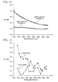
- FIG. 12 is a simulated noise figure NF as a function of wavelength ⁇ ;
- FIG. 13 illustrates noise figure NF as a function of wavelength ⁇
- FIG. 14 illustrates simulated sensitivity of noise figure NF as a function of first coil length
- FIGS. 15A-15E are a schematic diagrams illustrating additional exemplary optical fiber amplifiers.
- an improved dual pumping technique overcomes difficulty associated with prior art, and that the optical amplifier utilizing this dual pumping technique exhibits very low noise level and has approximately 40% higher efficiency than the prior art optical amplifiers.
- this technique utilizes two pumps operating at the same wavelength.
- both pumps operate at a wavelength of 1480 nm and the optical amplifier utilizes multiple coils (stages) of Erbium doped fiber.
- FIG. 4 illustrates an exemplary optical amplifier 5 .
- This optical amplifier utilizes two optical waveguides 10 a and 10 b which may be, for example, an active optical fiber having an inner core of a first optical material and an outer cladding of a different material.
- the materials used for the inner core and outer cladding have different indices of refraction so that the light propagates in a confined manner through the waveguide.
- the optical waveguide comprises a host material, preferably of glass, that contains a rare earth dopant.
- a host material preferably of glass
- a rare earth dopant may be used for this purpose.
- Erbium dopped silica fiber is used as an example in this embodiment, the use of other example materials will be apparent to those having skill in the art.
- the optical amplifier 5 has a first pump 20 a that serves as the primary pump. This pump is used to excite a population of rare earth ions within the optical material, raising them from their ground energy state to a metastable energy state.
- the metastable energy state is characterized by a comparatively long fluorescence lifetime, usually greater than 10 microseconds.
- the optical amplifier 5 illustrated in FIG. 4 includes an input port 30 into which an optical input signal S 1 may be introduced.
- the input port 30 couples the input optical signal S 1 into the first optical waveguide 10 a (comprising a coiled active fiber) whereby amplification is produced by stimulated emission of photons from the metastable energy state.
- a second optical waveguide 10 b, also comprising a coiled active fiber is arranged downstream of the first optical waveguide 10 a.
- the optical waveguide 10 b further amplifies optical signal provided by the waveguide 10 a.
- the second optical waveguide 10 b is coupled to the output port 40 , from which the amplified optical signal exits the amplifier 5 .
- the second pump 20 b is coupled to the second optical waveguide 10 b and serves to excite the population of rare earth atoms in the optical material of the waveguide 10 b by raising them to the metastable energy state.
- the amplified optical signal exiting the first waveguide, 10 a is used as an input signal for the waveguide 10 b and, as stated above, is further amplified by this waveguide, 10 b.
- the amplifier 5 may include an input stage 44 , a mid stage 46 and an output stage 48 .
- These stages may include components such as coupler(s), wavelength division (de)multiplexer(s), dispersion compensator(s), filter(s), isolator(s), attenuator(s) such as variable optical attenuator(s), and/or gain flattener(s), for example.
- components such as coupler(s), wavelength division (de)multiplexer(s), dispersion compensator(s), filter(s), isolator(s), attenuator(s) such as variable optical attenuator(s), and/or gain flattener(s), for example.
- the pump power of the first stage pumps 10 a is 140 mW.
- the second waveguide 10 b is pumped by two 1480 nm pumps 20 b to achieve good power conversion (i.e. high efficiencies).
- the pump power for the pumps 20 b was varied between 130 mW and 185 mW.
- the length of the coiled fiber of the waveguide 10 a was over 12 meters.
- the results obtained from the simulated modeling of the amplifiers and from the actual measurements are discussed below.
- the analysis compares amplifiers that utilize a first pump 20 a that provides either a 980 nm (case I), 1480 nm (case II) or 1510 nm (case III) pumping wavelength.
- the performance metrics are amplifier noise figure (NF) and second stage pump power (i.e. the pump power of the pump 20 b ).
- FIG. 5 shows the maximum NF (noise figure) as a function of coil length ratio between the first stage (waveguide 10 a ) and second stage (waveguide 10 b ) for the three amplifier simulation models. It is clear from the simulation results that the maximum NF produced when the pump 20 a operates at either 1480 nm or 980 nm wavelength is about the same. However, as can be seen from this figure, pumping with the 1510 nm pump 20 a results in a significant degradation of NF. Pumping at different wavelengths on the first stage of the optical amplifier results in different front-end inversions due to the differences in absorption and emission coefficients at the pump wavelength of the pump 20 a. For L-band amplifier, the front-end inversions for 980 nm and 1480 nm pumping are approximately the same due to a higher BASE (backward amplifier spontaneous emission) saturation in the 980 nm case.
- BASE backward amplifier spontaneous emission
- FIG. 6 shows the inversion profile along the first coil of the Er-doped fiber using different forward pumping pumps 20 a that operate at the same power (140 mW) but at different wavelengths. These wavelengths are 980 nm, 1480 nm, and 1510 nm. As stated above, the higher inversion at the front end of the optical amplifier results in lower noise figure. There is a clear saturation of the inversion at the front end of the amplifier when the 980 nm pump is being used. This is the result of strong ASE from the accumulation of the BASE at the front end of the optical amplifier.
- the inversion saturation corresponding to the 1480 nm pump is significantly lower than that of a 980 nm pump, while the inversion profile corresponding to the 1510 nm pump shows no saturation of the front end inversion.
- the 1480 nm pump 20 a has lower BASE than the 980 nm pump, and because of this, the front end inversion of the 1480 nm and 980 nm pumps is about the same. Therefore, surprisingly, these two pumps 20 a (1480 nm and 980 nm) provide about the same noise figure NF.
- the 1480 nm pump provides significantly higher power for L-band operation than the 980 nm pump and is less expensive to manufacture than the 980 nm pump.
- FIG. 7 illustrates the second stage pump power requirement as a function of coil length ratio between the first stage and second stages, when the first pump 20 a operates at either 980 nm, 1480 nm, or 1510 nm wavelengths.
- the vertical axis represents pump power of the pump 20 b in milliwats (mW).
- FIG. 7 illustrates that there is a reduction of pump power requirement (at coil ratios of about 0.16 or higher) when pumping at 1480 nm and 1510 nm compared to 980 nm pumping. Such reduction in pump power requirement will provide better pump margin for amplifier operation.
- FIG. 8 shows the NF spectrum (NF as a function of wavelength) from the above simulation.
- This NF spectrum is for the optimized coil ratio for each pumping configuration.
- the optimized coil ratio is about 0.3 and is determined by the ratio that results in the lowest noise figure (NF) for a given pump wavelength.
- FIG. 10 illustrates that pumping with the wavelengths of 980 nm and 1480 nm produce an equivalent noise figure performance, while a 1510 nm pumping configuration results in worse NF spectra for the L-band optical amplifiers.
- FIG. 9 Experimental results on the NF spectra for the two stage EDFA that utilizes a 1480 nm first pump 20 a and for the similar EDFA that utilizes a conventional 980 nm first pump 20 a are shown in FIG. 9 .
- the results are obtained from the same optical amplifier utilizing first a 980 nm first stage pump 20 a and then utilizing a 1480 nm first stage pump 20 a.
- the first stage pumps 20 a operated at a fixed coil ratio of 40%.
- an all 1480 nm pumping configuration shows very good NF performance as compared to pumping configuration that utilizes a 980 nm first stage pump. This is consistent with the results from the simulation. With this configuration (the pump 20 a providing laser beam at 1480 nm wavelength) we have observed a reduction of the total pump power by about 35%.
- FIG. 10 illustrates another exemplary optical amplifier. This optical amplifier is similar to the amplifier in FIG. 4, but utilizes only one (forward pumping) 1480 nm pump 20 b, coupled to the second EDF coil of the waveguide 10 b.
- BASE needs to be removed or further minimized in order to avoid saturation of the inversion at the front end of the amplifier. This is done by placing an isolator between the first two gain stages of the amplifier, preferably in combination with forward 1480 nm pump in the first stage of the amplifier. Furthermore, as described below, the length of the fiber constituting the first gain stage was significantly reduced.
- FIG. 11 illustrates a third example of an L-band amplifier.
- This amplifier is similar to the amplifier of FIG. 10, but includes three gain stages (three amplification coils). More specifically, the active fiber of the first optical waveguide 10 a of the amplifier of FIG. 10 has been split to form two sets of coiled fiber, thereby forming waveguides 10 a′ and 10 a′′.
- the amplifier 5 of FIG. 11 includes an isolator 50 located between the waveguides 10 a′ and 10 a′′. This isolator 50 blocks BASE, passes 1480 nm pump light and significantly reduces MPI (multipath interference), which is another critical factor in amplifier performance.
- MPI multipath interference
- FIG. 12 shows the simulated noise figure NF as a function of the wavelength ⁇ for the amplifiers illustrated in FIGS. 10 and 11. It is clear from the simulation that the amplifier of FIG. 11 has a dramatically reduced NF (by as much as 0.5 dB) when compared to the amplifier of FIG. 10 . To verify the results of the simulation, an experiment is performed using the two-coil and three-coil amplifiers similar to those of FIGS. 10 and 11. The result is shown in FIG. 13 . This figure also indicates that the use of a shorter fiber in the first coil of active fiber and the use of an isolator in conjunction with the forward pumping first pump improves NF by as much as 0.5 dB.
- the length of the active fiber forming the first stage (i.e., the fiber coil of the waveguide 10 a′ ) was then varied and the impact of the length of the fiber on the NF as observed.
- FIG. 14 illustrates simulated sensitivity of maximum NF for the amplifier of FIG. 11 as a function of the length of the active fiber that forms the first coil of this amplifier.
- FIG. 14 shows that there is an optimum fiber length when the amplifier achieves the lowest NF performance, which is about 3 meters in this amplifier. This coil provides 8 dB gain at the wavelength of 1570 nm.
- This figure also illustrates that the stability of the NF to the change of fiber length is very good. There is a tolerance of about ⁇ 1 m in the length of the active fiber forming the wave guide 10 a′ that results in low NF. Thus, the length of the active fiber forming the coil of the waveguides 10 a′ of the amplifier shown in FIG. 11 is very short. It is about 3 meters.
- the length of the active fiber forming the coil of the waveguide 10 a′′ is significantly longer—about 10 meters.
- the novel L-band EDFA amplifier of FIG. 11 also exhibits much lower MPI (multipath interference) than that of the amplifier of FIG. 10 .
- MPI is an additional noise to ASE.
- MPI accumulates along the fiber optic system with multiple amplification nodes.
- the length of the first coil of the amplifier of FIG. 11 is significantly reduced (from more than 10 meters to around 2 meters) when compared with that of the amplifier of FIG. 10 .
- the MPI is reduced by about 20 dB, which is a tremendous relaxation of the system budget.
- an isolator has to be used at the front end of the amplifier, which degrades amplifier NF by an additional amount of about 0.5 dB.
- the amplifier of FIG. 11 provides an improvement in NF of about 1.0 dB when compared with the amplifier of FIG. 10 .
- the amplifier of FIG. 11, when compared with the amplifier of FIG. 10, has the BASE reduced by approximately 15 dB. This will help improve system performance significantly as well.
- the optimum length of the first coil may change.
- the optimum length of the first coil can be easily determined when NF is plotted as a function of the length of the first coil.
- this optimum length is determined by the absorption coefficient of the active fiber. For example, if the absorption coefficient of a new fiber is smaller than in the fiber used in the above examples, the optimum coil length for the first coil will be increased to achieve the same BASE power.
- FIGS. 15A-15E Five more exemplary L-band amplifiers with low NF are shown in FIGS. 15A-15E. These amplifiers utilize one or more of the features of the amplifier depicted in FIG. 11 . Depending on the power requirement of EDFA, two coils and three coils can be implemented using different numbers of pumps (1480 nm) for the best NF and power performance.
- FIG. 15A illustrates a two stage L-band EDFA (Erbium doped fiber amplifier) with a low NF.
- This amplifier operates at a relatively low power level.
- the preferred length of the EDF coil corresponding to the waveguide 10 a is about 3 meters.
- This first EDF coil is forward pumped with a 1480 nm pump 20 a.
- the preferred length of the EDF coil corresponding to the waveguide 10 b is about 8-25 meters.
- An isolator 50 is located between the two waveguides 10 a and 10 b.
- the amplifier depicted in FIG. 15B is similar to the amplifier of FIG. 15 A. However, the amplifier of FIG. 15B utilizes a backward pumping 1480 nm pump 20 b that is coupled to the waveguide 10 b. The first stage of this amplifier (corresponding to the waveguide 10 a has an Erbium doped coil which is about 3 meters long.
- the amplifier depicted in FIG. 15C is similar to the amplifier of FIG. 11 but it utilizes two additional 1480 nm backward pumping pumps 20 a′ and 20 b.
- the amplifier depicted in FIG. 15D is similar to the amplifier of FIG. 15C but it utilizes several different pumps 20 b.
- the pumps 20 b of this EDFA operate at different wavelengths, for pump multiplexing.
- the amplifier depicted in FIG. 15E is similar to the amplifier of FIG. 15 B. However, the amplifier of FIG. 15E utilizes a forward pumping 980 nm pump 20 a and backward pumping 1480 nm pump 20 b.
- the first stage of this amplifier (corresponding to the waveguide 10 a ) has an Erbium doped coil which is about 3 meters long.
- the second Erbium doped coil (corresponding to the waveguide 10 b ) is about 20 meters long.
- An isolator 50 is located between the two coils.
- a wave division multiplexer 52 couples the 980 nm pump to the first waveguide 10 a.
- a second wave division multiplexer (WDM) 54 is located between the two waveguides 10 a and 10 b.
- the multiplexer 54 separates the 980 nm pump light exiting the first waveguide from the signal carrying light.
- the signal carrying light passes through the isolator 50 and enters the waveguide 10 b.
- the 980 nm light exiting the WDM 54 is routed around the isolator 50 and is multiplexed, with a WDM 56 , to the waveguide 10 b.
Landscapes
- Physics & Mathematics (AREA)
- Electromagnetism (AREA)
- Engineering & Computer Science (AREA)
- Plasma & Fusion (AREA)
- Optics & Photonics (AREA)
- Lasers (AREA)
Abstract
Description
Claims (22)
Priority Applications (6)
| Application Number | Priority Date | Filing Date | Title |
|---|---|---|---|
| US09/526,892 US6381063B1 (en) | 2000-03-16 | 2000-03-16 | Long band optical amplifier |
| DE60140522T DE60140522D1 (en) | 2000-03-16 | 2001-01-19 | OPTICAL L-BAND AMPLIFIER |
| EP01904959A EP1264371B1 (en) | 2000-03-16 | 2001-01-19 | Long band optical amplifier |
| PCT/US2001/001951 WO2001071862A1 (en) | 2000-03-16 | 2001-01-19 | Long band optical amplifier |
| AU2001232885A AU2001232885A1 (en) | 2000-03-16 | 2001-01-19 | Long band optical amplifier |
| TW090106399A TW511324B (en) | 2000-03-16 | 2001-03-17 | An improved long band optical amplifier |
Applications Claiming Priority (1)
| Application Number | Priority Date | Filing Date | Title |
|---|---|---|---|
| US09/526,892 US6381063B1 (en) | 2000-03-16 | 2000-03-16 | Long band optical amplifier |
Publications (1)
| Publication Number | Publication Date |
|---|---|
| US6381063B1 true US6381063B1 (en) | 2002-04-30 |
Family
ID=24099250
Family Applications (1)
| Application Number | Title | Priority Date | Filing Date |
|---|---|---|---|
| US09/526,892 Expired - Lifetime US6381063B1 (en) | 2000-03-16 | 2000-03-16 | Long band optical amplifier |
Country Status (6)
| Country | Link |
|---|---|
| US (1) | US6381063B1 (en) |
| EP (1) | EP1264371B1 (en) |
| AU (1) | AU2001232885A1 (en) |
| DE (1) | DE60140522D1 (en) |
| TW (1) | TW511324B (en) |
| WO (1) | WO2001071862A1 (en) |
Cited By (9)
| Publication number | Priority date | Publication date | Assignee | Title |
|---|---|---|---|---|
| US20020093728A1 (en) * | 2000-12-15 | 2002-07-18 | Yasushi Sugaya | Optical amplifier and method for amplifying wavelength multiplexed transmission signal light |
| US20030058526A1 (en) * | 2001-09-26 | 2003-03-27 | Sumitomo Electric Industries, Ltd. | Optical amplifier and optical transmission system using it |
| US6549315B1 (en) * | 1999-07-30 | 2003-04-15 | Sumitomo Electric Industries, Ltd. | Optical transmission system and optical amplifying apparatus, optical amplifying unit, and optical coupler for the same |
| US20030123141A1 (en) * | 2001-11-19 | 2003-07-03 | Aydin Yeniay | L band optical amplifier |
| US6781748B2 (en) | 2001-09-28 | 2004-08-24 | Photon-X, Llc | Long wavelength optical amplifier |
| US20070165298A1 (en) * | 2003-08-13 | 2007-07-19 | Atsushi Seki | Optical amplifier apparatus |
| CN102513693A (en) * | 2011-11-04 | 2012-06-27 | 杭州奥克光电设备有限公司 | High-power optical fiber laser welding machine |
| US20130070793A1 (en) * | 2011-09-16 | 2013-03-21 | Kabushiki Kaisha Toshiba | Fiber laser |
| WO2013090549A3 (en) * | 2011-12-13 | 2014-12-04 | Ofs Fitel, Llc | Multi-core erbium-doped fiber amplifier |
Citations (6)
| Publication number | Priority date | Publication date | Assignee | Title |
|---|---|---|---|---|
| US5185826A (en) * | 1992-02-07 | 1993-02-09 | At&T Bell Laboratories | Hybrid pumping arrangement for doped fiber amplifiers |
| US5260816A (en) * | 1991-09-24 | 1993-11-09 | Kokusai Denshin Denwa Co., Ltd. | Optical amplifier with erbium-doped fiber |
| US5295217A (en) * | 1991-07-02 | 1994-03-15 | Alcatel N. V. | Amplifier having an amplifying optical fiber |
| US5430572A (en) * | 1993-09-30 | 1995-07-04 | At&T Corp. | High power, high gain, low noise, two-stage optical amplifier |
| US5731892A (en) * | 1996-04-22 | 1998-03-24 | Lucent Technologies Inc. | Article comprising hybrid optical fiber amplifier |
| US5852510A (en) * | 1994-07-25 | 1998-12-22 | Pirelli Cavi S.P.A. | Amplified telecommunication system for wavelength-division multiplexing transmission having an equalized reception power |
Family Cites Families (3)
| Publication number | Priority date | Publication date | Assignee | Title |
|---|---|---|---|---|
| US5140456A (en) * | 1991-04-08 | 1992-08-18 | General Instrument Corporation | Low noise high power optical fiber amplifier |
| JPH10163554A (en) * | 1996-11-27 | 1998-06-19 | Furukawa Electric Co Ltd:The | Optical fiber amplifier |
| US5920424A (en) * | 1997-02-18 | 1999-07-06 | Lucent Technologies Inc. | Article comprising a broadband optical fiber amplifier |
-
2000
- 2000-03-16 US US09/526,892 patent/US6381063B1/en not_active Expired - Lifetime
-
2001
- 2001-01-19 AU AU2001232885A patent/AU2001232885A1/en not_active Abandoned
- 2001-01-19 WO PCT/US2001/001951 patent/WO2001071862A1/en active Application Filing
- 2001-01-19 DE DE60140522T patent/DE60140522D1/en not_active Expired - Lifetime
- 2001-01-19 EP EP01904959A patent/EP1264371B1/en not_active Expired - Lifetime
- 2001-03-17 TW TW090106399A patent/TW511324B/en active
Patent Citations (6)
| Publication number | Priority date | Publication date | Assignee | Title |
|---|---|---|---|---|
| US5295217A (en) * | 1991-07-02 | 1994-03-15 | Alcatel N. V. | Amplifier having an amplifying optical fiber |
| US5260816A (en) * | 1991-09-24 | 1993-11-09 | Kokusai Denshin Denwa Co., Ltd. | Optical amplifier with erbium-doped fiber |
| US5185826A (en) * | 1992-02-07 | 1993-02-09 | At&T Bell Laboratories | Hybrid pumping arrangement for doped fiber amplifiers |
| US5430572A (en) * | 1993-09-30 | 1995-07-04 | At&T Corp. | High power, high gain, low noise, two-stage optical amplifier |
| US5852510A (en) * | 1994-07-25 | 1998-12-22 | Pirelli Cavi S.P.A. | Amplified telecommunication system for wavelength-division multiplexing transmission having an equalized reception power |
| US5731892A (en) * | 1996-04-22 | 1998-03-24 | Lucent Technologies Inc. | Article comprising hybrid optical fiber amplifier |
Non-Patent Citations (4)
| Title |
|---|
| Espindola, R.P. et al., Low noise, high gain, high conversion efficiency L-band EDFA, Technical Digest of the 10th Optical Amplifier and Their Application, Nara, Japan (1999). |
| Nillson et al, IEEE Photonics Technology Letters, vol. 10, #11, pp. 1551-1553; 12/98.* * |
| Takano et al, Proceedings of 1995 IEICE Gen. Conf., B-1067, p. 513, 3/95. * |
| Tanaka et al, Optical Society of America, vol. 13, ThD4-1-4; 7/91.* * |
Cited By (14)
| Publication number | Priority date | Publication date | Assignee | Title |
|---|---|---|---|---|
| US6549315B1 (en) * | 1999-07-30 | 2003-04-15 | Sumitomo Electric Industries, Ltd. | Optical transmission system and optical amplifying apparatus, optical amplifying unit, and optical coupler for the same |
| US20020093728A1 (en) * | 2000-12-15 | 2002-07-18 | Yasushi Sugaya | Optical amplifier and method for amplifying wavelength multiplexed transmission signal light |
| US6891662B2 (en) * | 2000-12-15 | 2005-05-10 | Fujitsu Limited | Optical amplifier and method for amplifying wavelength multiplexed transmission signal light |
| US6954305B2 (en) * | 2001-09-26 | 2005-10-11 | Sumitomo Electric Industries, Ltd. | Optical amplifier and optical transmission system using it |
| US20030058526A1 (en) * | 2001-09-26 | 2003-03-27 | Sumitomo Electric Industries, Ltd. | Optical amplifier and optical transmission system using it |
| US6781748B2 (en) | 2001-09-28 | 2004-08-24 | Photon-X, Llc | Long wavelength optical amplifier |
| US20030123141A1 (en) * | 2001-11-19 | 2003-07-03 | Aydin Yeniay | L band optical amplifier |
| US20070165298A1 (en) * | 2003-08-13 | 2007-07-19 | Atsushi Seki | Optical amplifier apparatus |
| US7609437B2 (en) * | 2003-08-13 | 2009-10-27 | Advantest Corporation | Optical amplifier apparatus |
| US20130070793A1 (en) * | 2011-09-16 | 2013-03-21 | Kabushiki Kaisha Toshiba | Fiber laser |
| CN102513693A (en) * | 2011-11-04 | 2012-06-27 | 杭州奥克光电设备有限公司 | High-power optical fiber laser welding machine |
| CN102513693B (en) * | 2011-11-04 | 2014-08-06 | 杭州奥克光电设备有限公司 | High-power optical fiber laser welding machine |
| WO2013090549A3 (en) * | 2011-12-13 | 2014-12-04 | Ofs Fitel, Llc | Multi-core erbium-doped fiber amplifier |
| JP2015510253A (en) * | 2011-12-13 | 2015-04-02 | オーエフエス ファイテル,エルエルシー | Multi-core erbium-doped fiber amplifier |
Also Published As
| Publication number | Publication date |
|---|---|
| AU2001232885A1 (en) | 2001-10-03 |
| DE60140522D1 (en) | 2009-12-31 |
| EP1264371B1 (en) | 2009-11-18 |
| EP1264371A1 (en) | 2002-12-11 |
| TW511324B (en) | 2002-11-21 |
| WO2001071862A1 (en) | 2001-09-27 |
Similar Documents
| Publication | Publication Date | Title |
|---|---|---|
| JP4900501B2 (en) | Optical amplifier and optical amplification method | |
| Harun et al. | Gain enhancement in L-band EDFA through a double-pass technique | |
| US6407853B1 (en) | Broadhead dual wavelength pumped fiber amplifier | |
| US6141142A (en) | Article comprising an L-Band optical fiber amplifier | |
| WO2000024094A1 (en) | Management and utilization of ase in optical amplifier | |
| US7113328B2 (en) | Dual-wavelength pumped thulium-doped optical fiber amplifier | |
| Choi et al. | High-gain coefficient long-wavelength-band erbium-doped fiber amplifier using 1530-nm band pump | |
| US6381063B1 (en) | Long band optical amplifier | |
| KR20030068230A (en) | Long-band erbium doped fiber amplifier | |
| US6556342B1 (en) | Thulium doped fiber pump for pumping Raman amplifiers | |
| Roy et al. | Noise and gain band management of thulium-doped fiber amplifier with dual-wavelength pumping schemes | |
| US6421172B1 (en) | Long band optical amplifier | |
| EP1096703A9 (en) | Long-band light source for testing optical elements using feedback loop | |
| JP2002232044A (en) | Optical fiber amplifier | |
| US6441954B1 (en) | Optical amplifier with wide flat gain dynamic range | |
| Yeniay et al. | Single stage high power L-band EDFA with multiple C-band seeds | |
| Ono et al. | 1.58 µm band fluoride-based Er3+-doped fibre amplifier for WDM transmission systems | |
| Karasek | The design of L-band EDFA for multiwavelength applications | |
| Yadlowsky | Independent control of EDFA gain shape and magnitude using excited-state trapping | |
| US6624928B1 (en) | Raman amplification | |
| Lee et al. | Investigation of Amplifying Mechanism in an t-Band Erbium-Doped Fiber Amplifier Pumped by a 980 nm Pump | |
| Artiglia et al. | Optical fibre amplifiers: physical model and design issues | |
| Kaur et al. | Role of an isolator in optimization of forward conversion efficiency in an Er-doped SFS source at 1.55 μm | |
| Maes et al. | High power BDF/EDF hybrid amplifier providing 27 dB gain over 90 nm in the $\mathrm {E}+\mathrm {S} $ band | |
| Abdul-Rashid et al. | Shorter wavelength gain shift in EDFA using a macro-bending approach |
Legal Events
| Date | Code | Title | Description |
|---|---|---|---|
| AS | Assignment |
Owner name: CORNING INCORPORATED, NEW YORK Free format text: ASSIGNMENT OF ASSIGNORS INTEREST;ASSIGNOR:LIU, YONGQIAN;REEL/FRAME:010683/0391 Effective date: 20000314 |
|
| STCF | Information on status: patent grant |
Free format text: PATENTED CASE |
|
| AS | Assignment |
Owner name: AVANEX CORPORATION, CALIFORNIA Free format text: ASSIGNMENT OF ASSIGNORS INTEREST;ASSIGNORS:CORNING INCORPORATED;CORNING PHOTONIC TECHNOLOGIES, INC.;CORNING LASERTRON, INC.;AND OTHERS;REEL/FRAME:014090/0245 Effective date: 20030731 |
|
| FEPP | Fee payment procedure |
Free format text: PAYOR NUMBER ASSIGNED (ORIGINAL EVENT CODE: ASPN); ENTITY STATUS OF PATENT OWNER: LARGE ENTITY |
|
| AS | Assignment |
Owner name: HBK INVESTMENTS L.P., TEXAS Free format text: SECURITY AGREEMENT;ASSIGNOR:AVANEX CORPORATION;REEL/FRAME:016079/0174 Effective date: 20050519 |
|
| FPAY | Fee payment |
Year of fee payment: 4 |
|
| AS | Assignment |
Owner name: AVANEX CORPORATION, CALIFORNIA Free format text: RELEASE BY SECURED PARTY;ASSIGNOR:HBK INVESTMENTS, L.P.;REEL/FRAME:019035/0342 Effective date: 20070312 |
|
| FPAY | Fee payment |
Year of fee payment: 8 |
|
| AS | Assignment |
Owner name: WELLS FARGO CAPITAL FINANCE, INC., AS AGENT, CALIF Free format text: PATENT SECURITY AGREEMENT;ASSIGNOR:OCLARO (NORTH AMERICA), INC.;REEL/FRAME:028487/0211 Effective date: 20110726 |
|
| FPAY | Fee payment |
Year of fee payment: 12 |
|
| AS | Assignment |
Owner name: OCLARO (NORTH AMERICA), INC., CALIFORNIA Free format text: ASSIGNMENT OF ASSIGNORS INTEREST;ASSIGNOR:AVANEX CORPORATION;REEL/FRAME:032494/0343 Effective date: 20090707 |
|
| AS | Assignment |
Owner name: II-VI INCORPORATED, PENNSYLVANIA Free format text: ASSIGNMENT OF ASSIGNORS INTEREST;ASSIGNORS:OCLARO TECHNOLOGY LIMITED;OCLARO, INC.;OCLARO (NORTH AMERICA), INC.;AND OTHERS;REEL/FRAME:032554/0818 Effective date: 20131101 |
|
| AS | Assignment |
Owner name: OCLARO, INC., CALIFORNIA Free format text: RELEASE OF SECURITY INTEREST;ASSIGNOR:WELLS FARGO CAPITAL FINANCE, LLC;REEL/FRAME:032982/0222 Effective date: 20131101 Owner name: OCLARO TECHNOLOGY LIMITED, CALIFORNIA Free format text: RELEASE OF SECURITY INTEREST;ASSIGNOR:WELLS FARGO CAPITAL FINANCE, LLC;REEL/FRAME:032982/0222 Effective date: 20131101 |
|
| AS | Assignment |
Owner name: BANK OF AMERICA, N.A., AS ADMINISTRATIVE AGENT, NO Free format text: NOTICE OF GRANT OF SECURITY INTEREST IN PATENTS;ASSIGNORS:II-VI INCORPORATED;MARLOW INDUSTRIES, INC.;EPIWORKS, INC.;AND OTHERS;REEL/FRAME:050484/0204 Effective date: 20190924 Owner name: BANK OF AMERICA, N.A., AS ADMINISTRATIVE AGENT, NORTH CAROLINA Free format text: NOTICE OF GRANT OF SECURITY INTEREST IN PATENTS;ASSIGNORS:II-VI INCORPORATED;MARLOW INDUSTRIES, INC.;EPIWORKS, INC.;AND OTHERS;REEL/FRAME:050484/0204 Effective date: 20190924 |
|
| AS | Assignment |
Owner name: II-VI DELAWARE, INC., DELAWARE Free format text: ASSIGNMENT OF ASSIGNORS INTEREST;ASSIGNOR:II-VI INCORPORATED;REEL/FRAME:051210/0411 Effective date: 20191202 |
|
| AS | Assignment |
Owner name: PHOTOP TECHNOLOGIES, INC., CALIFORNIA Free format text: PATENT RELEASE AND REASSIGNMENT;ASSIGNOR:BANK OF AMERICA, N.A., AS ADMINISTRATIVE AGENT;REEL/FRAME:060574/0001 Effective date: 20220701 Owner name: II-VI OPTOELECTRONIC DEVICES, INC., NEW JERSEY Free format text: PATENT RELEASE AND REASSIGNMENT;ASSIGNOR:BANK OF AMERICA, N.A., AS ADMINISTRATIVE AGENT;REEL/FRAME:060574/0001 Effective date: 20220701 Owner name: II-VI DELAWARE, INC., PENNSYLVANIA Free format text: PATENT RELEASE AND REASSIGNMENT;ASSIGNOR:BANK OF AMERICA, N.A., AS ADMINISTRATIVE AGENT;REEL/FRAME:060574/0001 Effective date: 20220701 Owner name: II-VI PHOTONICS (US), INC., MASSACHUSETTS Free format text: PATENT RELEASE AND REASSIGNMENT;ASSIGNOR:BANK OF AMERICA, N.A., AS ADMINISTRATIVE AGENT;REEL/FRAME:060574/0001 Effective date: 20220701 Owner name: M CUBED TECHNOLOGIES, INC., CONNECTICUT Free format text: PATENT RELEASE AND REASSIGNMENT;ASSIGNOR:BANK OF AMERICA, N.A., AS ADMINISTRATIVE AGENT;REEL/FRAME:060574/0001 Effective date: 20220701 Owner name: II-VI OPTICAL SYSTEMS, INC., CALIFORNIA Free format text: PATENT RELEASE AND REASSIGNMENT;ASSIGNOR:BANK OF AMERICA, N.A., AS ADMINISTRATIVE AGENT;REEL/FRAME:060574/0001 Effective date: 20220701 Owner name: FINISAR CORPORATION, CALIFORNIA Free format text: PATENT RELEASE AND REASSIGNMENT;ASSIGNOR:BANK OF AMERICA, N.A., AS ADMINISTRATIVE AGENT;REEL/FRAME:060574/0001 Effective date: 20220701 Owner name: OPTIUM CORPORATION, CALIFORNIA Free format text: PATENT RELEASE AND REASSIGNMENT;ASSIGNOR:BANK OF AMERICA, N.A., AS ADMINISTRATIVE AGENT;REEL/FRAME:060574/0001 Effective date: 20220701 Owner name: COADNA PHOTONICS, INC., PENNSYLVANIA Free format text: PATENT RELEASE AND REASSIGNMENT;ASSIGNOR:BANK OF AMERICA, N.A., AS ADMINISTRATIVE AGENT;REEL/FRAME:060574/0001 Effective date: 20220701 Owner name: KAILIGHT PHOTONICS, INC., CALIFORNIA Free format text: PATENT RELEASE AND REASSIGNMENT;ASSIGNOR:BANK OF AMERICA, N.A., AS ADMINISTRATIVE AGENT;REEL/FRAME:060574/0001 Effective date: 20220701 Owner name: LIGHTSMYTH TECHNOLOGIES, INC., OREGON Free format text: PATENT RELEASE AND REASSIGNMENT;ASSIGNOR:BANK OF AMERICA, N.A., AS ADMINISTRATIVE AGENT;REEL/FRAME:060574/0001 Effective date: 20220701 Owner name: EPIWORKS, INC., ILLINOIS Free format text: PATENT RELEASE AND REASSIGNMENT;ASSIGNOR:BANK OF AMERICA, N.A., AS ADMINISTRATIVE AGENT;REEL/FRAME:060574/0001 Effective date: 20220701 Owner name: MARLOW INDUSTRIES, INC., TEXAS Free format text: PATENT RELEASE AND REASSIGNMENT;ASSIGNOR:BANK OF AMERICA, N.A., AS ADMINISTRATIVE AGENT;REEL/FRAME:060574/0001 Effective date: 20220701 Owner name: II-VI INCORPORATED, PENNSYLVANIA Free format text: PATENT RELEASE AND REASSIGNMENT;ASSIGNOR:BANK OF AMERICA, N.A., AS ADMINISTRATIVE AGENT;REEL/FRAME:060574/0001 Effective date: 20220701 |