US6386159B1 - Valve timing system - Google Patents
Valve timing system Download PDFInfo
- Publication number
- US6386159B1 US6386159B1 US09/171,363 US17136398A US6386159B1 US 6386159 B1 US6386159 B1 US 6386159B1 US 17136398 A US17136398 A US 17136398A US 6386159 B1 US6386159 B1 US 6386159B1
- Authority
- US
- United States
- Prior art keywords
- cam
- cam follower
- contoured
- follower
- engagement surface
- Prior art date
- Legal status (The legal status is an assumption and is not a legal conclusion. Google has not performed a legal analysis and makes no representation as to the accuracy of the status listed.)
- Expired - Lifetime
Links
Images


Classifications
-
- F—MECHANICAL ENGINEERING; LIGHTING; HEATING; WEAPONS; BLASTING
- F01—MACHINES OR ENGINES IN GENERAL; ENGINE PLANTS IN GENERAL; STEAM ENGINES
- F01L—CYCLICALLY OPERATING VALVES FOR MACHINES OR ENGINES
- F01L1/00—Valve-gear or valve arrangements, e.g. lift-valve gear
- F01L1/12—Transmitting gear between valve drive and valve
- F01L1/14—Tappets; Push rods
- F01L1/143—Tappets; Push rods for use with overhead camshafts
-
- F—MECHANICAL ENGINEERING; LIGHTING; HEATING; WEAPONS; BLASTING
- F01—MACHINES OR ENGINES IN GENERAL; ENGINE PLANTS IN GENERAL; STEAM ENGINES
- F01L—CYCLICALLY OPERATING VALVES FOR MACHINES OR ENGINES
- F01L1/00—Valve-gear or valve arrangements, e.g. lift-valve gear
- F01L1/02—Valve drive
- F01L1/04—Valve drive by means of cams, camshafts, cam discs, eccentrics or the like
- F01L1/08—Shape of cams
-
- F—MECHANICAL ENGINEERING; LIGHTING; HEATING; WEAPONS; BLASTING
- F01—MACHINES OR ENGINES IN GENERAL; ENGINE PLANTS IN GENERAL; STEAM ENGINES
- F01L—CYCLICALLY OPERATING VALVES FOR MACHINES OR ENGINES
- F01L13/00—Modifications of valve-gear to facilitate reversing, braking, starting, changing compression ratio, or other specific operations
- F01L13/0015—Modifications of valve-gear to facilitate reversing, braking, starting, changing compression ratio, or other specific operations for optimising engine performances by modifying valve lift according to various working parameters, e.g. rotational speed, load, torque
- F01L13/0031—Modifications of valve-gear to facilitate reversing, braking, starting, changing compression ratio, or other specific operations for optimising engine performances by modifying valve lift according to various working parameters, e.g. rotational speed, load, torque by modification of tappet or pushrod length
-
- F—MECHANICAL ENGINEERING; LIGHTING; HEATING; WEAPONS; BLASTING
- F01—MACHINES OR ENGINES IN GENERAL; ENGINE PLANTS IN GENERAL; STEAM ENGINES
- F01L—CYCLICALLY OPERATING VALVES FOR MACHINES OR ENGINES
- F01L2307/00—Preventing the rotation of tappets
Definitions
- the present invention relates to a power output improvement apparatus for an internal combustion engine and in particular to a valve timing system for an internal combustion engine, which is also applicable to engines having multi-inlet and multi-exhaust configurations per combustion chamber.
- the present invention provides a variable valve timing system comprising:
- cam follower adapted to move the valve between its closed and open position, said follower having a contoured engagement surface
- a cam located on and driven by a cam shaft, and having a contact surface adapted to engage the engagement surface of the cam follower and move the cam follower to operate the valve, the contact surface of the cam being contoured at least along a portion thereof;
- rotational means to rotate the cam follower relative to the plane of movement of the cam such that the contoured contact surface of the cam and contoured engagement surface of the cam follower engage each other earlier and disengage later than if the cam follower is not rotated.
- FIG. 1 illustrates schematically a perspective view of a cam and cam follower of one embodiment of the present invention
- FIG. 2 illustrates schematically a side view of the cam and cam follower of another embodiment of the present invention
- FIG. 3 illustrates schematically a plan view of the cam follower shown in FIG. 2;
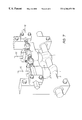
- FIG. 4 illustrates schematically a control rod assembly controlling four cam followers as illustrated in FIG. 3;
- FIGS. 4A and 4B show close-up portions of FIG. 4 as indicated.
- FIG. 5 illustrates schematically a close up view of the cam follower and rotational means shown in FIG. 4;
- FIG. 6 illustrates a plan view of the cam follower according to a further embodiment of the present invention
- FIG. 7 illustrates a perspective view of an embodiment of the present invention applied to a push rod engine
- FIG. 8 illustrates a sectional view through a cam follower assembly, in an overhead cam engine, illustrated in FIG. 7;
- FIG. 9 illustrates a schematic sectional view taken in the direction of arrow IX in FIG. 8 .
- the cam ( 1 ) has a contoured outer or contact surface ( 2 ).
- the contour can be of any desired profile, but is preferably v-shaped.
- the cam ( 1 ) is supported on the cam shaft ( 3 ) as is normal with internal combustion engines.
- the cam follower ( 4 ) operates the valve (not shown), and has a contoured upper engagement surface ( 5 ) of any desired configuration.
- the contour of the upper engagement surface ( 5 ) of the cam follower ( 4 ) and the contoured contact surface ( 2 ) of the cam ( 1 ) are complementary.
- the contour on the upper surface ( 5 ) of the cam follower ( 4 ) is a v-shaped recess ( 6 ), with the walls thereof at any desired angle.
- timing system of the present invention is the same as any standard timing system, in that as the cam shaft rotates at a speed determined by the engine speed such as at half the engine speed, the cam rotates around the cam shaft axis and the cam engagement surface on the lobe engages the cam follower, opening and closing the valve.
- the cam follower ( 4 ) is rotated about its axis ( 7 ) a desired number of degrees as shown in FIG. 3, in accordance with the engine speed.
- the v-shaped recess ( 6 ) and the complementary v-shaped contact surface ( 2 ) of the cam ( 1 ) are slightly out of alignment, so that the contact surface ( 2 ) of the cam lobe engages the inclined plane of the wall of the v-shaped recess ( 6 ) at a higher point, hence earlier in the cycle and disengage later, than when the v-shaped recess ( 6 ) and the complementary v-shaped contact surface ( 2 ) of the cam ( 1 ) are aligned. Therefore the valve is opened sooner and closed later, increasing the degrees of the cycle for which the valve is open, as the engine revolutions increase.
- two rocker inserts ( 8 ) are located in the v-shaped recess ( 6 ), to maintain the geometric integrity of the alignment of the contact faces of the cam ( 1 ) and cam follower ( 4 ), to lessen wear on the cam ( 1 ).
- the rocker inserts ( 8 ) are fitted into the cam follower ( 4 ) so that they can rotate about their respective axes ( 9 & 10 ), as they are engaged by the contoured contact surface ( 2 ) of the cam ( 1 ) during the rotation of the cam ( 1 ) and the reciprocated rotation of the cam follower.( 4 ).
- FIGS. 4 a - 5 c One method of rotating the cam follower ( 4 ) is shown in FIGS. 4 a - 5 c , wherein a control yoke ( 11 ) is pivotally attached, at one end, connected by two bolts ( 13 ) to the cam follower ( 4 ) and at its other end to a control rod ( 12 ).
- the yoke ( 11 ) is connected by a shaft ( 14 ) to a floating ball assembly ( 15 ) in the control rod ( 12 ).
- Adjustment of the angular positions of the cam followers ( 4 ) is carried out by means of an adjustment nut ( 16 ) which has a left hand threaded rod ( 17 ) and a right handed threaded rod ( 18 ) which engage in control rod ( 12 ).
- the movement of the control rod ( 12 ) could be computer controlled by the engine revolutions or the driving mode or centrifugally controlled.
- the rocker inserts ( 8 ) have their ends ( 19 ) which slide into respective grooves ( 20 ), to prevent the inserts ( 8 ) from falling out of their recesses ( 21 ).
- each engaging surface of the two rocker inserts of a particular cam follower and the respective complementary engaging surfaces of the cam could be different so that the valve is allowed to advance forward but with less delay in closing or with no delay in closing or vice versa.
- the engaging surfaces of the rocker inserts could slope from the periphery of the cam follower to the centre line ( 26 ) of the cam follower ( 4 ) ⁇ FIG. 3 ⁇ .
- an embodiment of the present invention is applicable to push rod engines.
- the control of the operation of the cam followers ( 4 ) and the cams ( 1 ) are the same as the other embodiments.
- camshaft ( 3 ), cam followers ( 4 ) and controls be located in a single assembly, which can be removed, as a whole, from the engine.
- FIG. 7 shows a paired inlet and outlet valve arrangement.
- the cam follower centre ( 7 ) is offset from the valve stem centre ( 23 ).
- a semi circular groove ( 24 ) is milled in the underside ( 25 ) of the cam follower ( 4 ) to take up the rotation of the cam follower ( 4 ) relative to the valve stem ( 27 ).
- the semi circular groove ( 24 ) can be milled to varying depths so that when the cam follower is rotated, the tappet clearance is maintained.
Abstract
A variable valve timing system applicable for varying the opening and closing cycle of the inlet and outlet valves of an internal combustion engine. The system comprises a cam follower and a cam which is rotated about the cam shaft to move the valve between its open and closed position. To vary the cycle of the opening and closing valves, a rotational means is connected to the cam follower to rotate the cam follower such that the cam follower and cam are out of alignment such that the cam lobe engages the contact surface at a higher point and hence earlier than if the cam follower and the cats are aligned. Therefore the valve is opened sooner and closed later, increasing the degrees of cycle for which the valve is open, for example, as the engine revolutions increase.
Description
The present invention relates to a power output improvement apparatus for an internal combustion engine and in particular to a valve timing system for an internal combustion engine, which is also applicable to engines having multi-inlet and multi-exhaust configurations per combustion chamber.
Many systems have been developed to increase the power output of internal combustion engines. Some of these utilise multiple valves, and variable valve timing such as BMW's patented Vanos variable valve timing system.
The present invention provides a variable valve timing system comprising:
a cam follower adapted to move the valve between its closed and open position, said follower having a contoured engagement surface;
a cam, located on and driven by a cam shaft, and having a contact surface adapted to engage the engagement surface of the cam follower and move the cam follower to operate the valve, the contact surface of the cam being contoured at least along a portion thereof; and
rotational means to rotate the cam follower relative to the plane of movement of the cam such that the contoured contact surface of the cam and contoured engagement surface of the cam follower engage each other earlier and disengage later than if the cam follower is not rotated.
The invention will now be described, by way of example, with reference to the accompanying drawings in which:
FIG. 1 illustrates schematically a perspective view of a cam and cam follower of one embodiment of the present invention;
FIG. 2 illustrates schematically a side view of the cam and cam follower of another embodiment of the present invention;
FIG. 3 illustrates schematically a plan view of the cam follower shown in FIG. 2;
FIG. 4 illustrates schematically a control rod assembly controlling four cam followers as illustrated in FIG. 3;
FIGS. 4A and 4B show close-up portions of FIG. 4 as indicated.
FIG. 5 illustrates schematically a close up view of the cam follower and rotational means shown in FIG. 4;
FIG. 6 illustrates a plan view of the cam follower according to a further embodiment of the present invention,
FIG. 7 illustrates a perspective view of an embodiment of the present invention applied to a push rod engine;
FIG. 8 illustrates a sectional view through a cam follower assembly, in an overhead cam engine, illustrated in FIG. 7; and
FIG. 9 illustrates a schematic sectional view taken in the direction of arrow IX in FIG. 8.
In one embodiment of the present invention, as shown in FIG. 1, the cam (1) has a contoured outer or contact surface (2). The contour can be of any desired profile, but is preferably v-shaped. The cam (1) is supported on the cam shaft (3) as is normal with internal combustion engines.
The cam follower (4) operates the valve (not shown), and has a contoured upper engagement surface (5) of any desired configuration. However preferably the contour of the upper engagement surface (5) of the cam follower (4) and the contoured contact surface (2) of the cam (1) are complementary. In the present embodiment the contour on the upper surface (5) of the cam follower (4) is a v-shaped recess (6), with the walls thereof at any desired angle.
The general operation of the timing system of the present invention is the same as any standard timing system, in that as the cam shaft rotates at a speed determined by the engine speed such as at half the engine speed, the cam rotates around the cam shaft axis and the cam engagement surface on the lobe engages the cam follower, opening and closing the valve.
However in the present invention the cam follower (4) is rotated about its axis (7) a desired number of degrees as shown in FIG. 3, in accordance with the engine speed. Thus the v-shaped recess (6) and the complementary v-shaped contact surface (2) of the cam (1) are slightly out of alignment, so that the contact surface (2) of the cam lobe engages the inclined plane of the wall of the v-shaped recess (6) at a higher point, hence earlier in the cycle and disengage later, than when the v-shaped recess (6) and the complementary v-shaped contact surface (2) of the cam (1) are aligned. Therefore the valve is opened sooner and closed later, increasing the degrees of the cycle for which the valve is open, as the engine revolutions increase.
In the embodiment shown in FIGS. 2 & 3, two rocker inserts (8) are located in the v-shaped recess (6), to maintain the geometric integrity of the alignment of the contact faces of the cam (1) and cam follower (4), to lessen wear on the cam (1). The rocker inserts (8) are fitted into the cam follower (4) so that they can rotate about their respective axes (9 & 10), as they are engaged by the contoured contact surface (2) of the cam (1) during the rotation of the cam (1) and the reciprocated rotation of the cam follower.(4).
One method of rotating the cam follower (4) is shown in FIGS. 4a-5 c, wherein a control yoke (11) is pivotally attached, at one end, connected by two bolts (13) to the cam follower (4) and at its other end to a control rod (12). The yoke (11) is connected by a shaft (14) to a floating ball assembly (15) in the control rod (12). Adjustment of the angular positions of the cam followers (4) is carried out by means of an adjustment nut (16) which has a left hand threaded rod (17) and a right handed threaded rod (18) which engage in control rod (12). The movement of the control rod (12) could be computer controlled by the engine revolutions or the driving mode or centrifugally controlled.
As shown in FIG. 6, the rocker inserts (8) have their ends (19) which slide into respective grooves (20), to prevent the inserts (8) from falling out of their recesses (21).
In other embodiments not shown the angles of each engaging surface of the two rocker inserts of a particular cam follower and the respective complementary engaging surfaces of the cam could be different so that the valve is allowed to advance forward but with less delay in closing or with no delay in closing or vice versa. Further the engaging surfaces of the rocker inserts could slope from the periphery of the cam follower to the centre line (26) of the cam follower (4) {FIG. 3}.
As shown in FIG. 7, an embodiment of the present invention is applicable to push rod engines. The control of the operation of the cam followers (4) and the cams (1) are the same as the other embodiments. However, because of the need for accessibility to set the adjustments relating to the variable valve timing, it would be preferable that that camshaft (3), cam followers (4) and controls be located in a single assembly, which can be removed, as a whole, from the engine. FIG. 7 shows a paired inlet and outlet valve arrangement.
As shown in FIGS. 8 & 9, the cam follower centre (7) is offset from the valve stem centre (23). A semi circular groove (24) is milled in the underside (25) of the cam follower (4) to take up the rotation of the cam follower (4) relative to the valve stem (27). The semi circular groove (24) can be milled to varying depths so that when the cam follower is rotated, the tappet clearance is maintained.
Incorporating hydraulic valve lifters in the design would most likely compensate for the slight variations in tappet clearances. This would mostly apply to push rod engines.
It should be obvious to people skilled in the art that modifications and variations could be made to the above described embodiments without departing from the spirit or the scope of the present invention.
Claims (4)
1. A variable valve timing system comprising:
a cam follower adapted to move a valve between its closed and open positions, said follower having a contoured engagement surface;
a cam, located on and driven by a cam shaft, and having a contact lift surface adapted to engage the engagement surface of the cam follower and move the cam follower to operate the valve, the contact surface of the cam being contoured at least along a portion thereof; and
rotational means to rotate the cam follower relative to the plane of movement of the cam such that the contoured contact surface of the cam and contoured engagement surface of the cam follower engage each other earlier and disengage each other later than if the cam follower is not rotated, wherein said rotational means comprises a control rod and each cam follower is held between two arms of a u-shaped yoke, with the yoke being connected by a shaft to a floating ball assembly on the control rod.
2. A variable valve timing system comprising:
a cam follower adapted to move a valve between its closed and open positions, said follower having a contoured engagement surface, said contoured engagement surface having a v-shape profile;
a cam, located on and driven by a cam shaft, and having a contact lift surface adapted to engage the engagement surface of the cam follower and move the cam follower to operate the valve, the contact surface of the cam being contoured at least along a portion thereof; and
rotational means to rotate the cam follower relative to the plane of movement of the cam such that the contoured contact surface of the cam and contoured engagement surface of the cam follower engage each other earlier and disengage each other later than if the cam follower is not rotated, wherein said rotational means comprises a control rod and each cam follower is held between two arms of a unshaped yoke, with the yoke being connected by a shaft to a floating ball assembly on the control rod.
3. A variable valve timing system according to claim 2 wherein two rocker inserts form the engagement surface of the cam follower.
4. A variable valve timing system according to claim 2 wherein the control rod has means to vary its length between each floating ball assembly so as to align the cam with the cam follower as required.
Applications Claiming Priority (3)
| Application Number | Priority Date | Filing Date | Title |
|---|---|---|---|
| AUPN9265A AUPN926596A0 (en) | 1996-04-16 | 1996-04-16 | Valve timing system |
| AUPN9265 | 1996-04-16 | ||
| PCT/AU1997/000237 WO1997039222A1 (en) | 1996-04-16 | 1997-04-16 | Valve timing system |
Publications (1)
| Publication Number | Publication Date |
|---|---|
| US6386159B1 true US6386159B1 (en) | 2002-05-14 |
Family
ID=3793579
Family Applications (1)
| Application Number | Title | Priority Date | Filing Date |
|---|---|---|---|
| US09/171,363 Expired - Lifetime US6386159B1 (en) | 1996-04-16 | 1997-04-16 | Valve timing system |
Country Status (9)
| Country | Link |
|---|---|
| US (1) | US6386159B1 (en) |
| EP (1) | EP0894185B1 (en) |
| JP (1) | JP3993238B2 (en) |
| AT (1) | ATE259933T1 (en) |
| AU (1) | AUPN926596A0 (en) |
| CA (1) | CA2251836C (en) |
| DE (1) | DE69727663T2 (en) |
| NZ (1) | NZ332370A (en) |
| WO (1) | WO1997039222A1 (en) |
Cited By (5)
| Publication number | Priority date | Publication date | Assignee | Title |
|---|---|---|---|---|
| US20060196459A1 (en) * | 2005-03-01 | 2006-09-07 | Manousos Pattakos | Discrete mode variable valve gear |
| US20070140871A1 (en) * | 2003-04-28 | 2007-06-21 | Bond Robert S | Cams and cam followers |
| US20130167788A1 (en) * | 2011-07-02 | 2013-07-04 | Man Truck & Bus Ag | Valve Control for at Least One of an Internal Combustion Engine |
| CN105464733A (en) * | 2015-12-08 | 2016-04-06 | 长春设备工艺研究所 | Concave spherical surface arc cam structure for engine cam drive |
| WO2018013461A1 (en) * | 2016-07-14 | 2018-01-18 | Borgwarner Inc. | Valve actuation system providing variable valve lift |
Families Citing this family (2)
| Publication number | Priority date | Publication date | Assignee | Title |
|---|---|---|---|---|
| US7506624B2 (en) | 2006-02-28 | 2009-03-24 | Perkins Engines Company Limited | Variable engine valve actuation system |
| LV13993B (en) * | 2008-02-21 | 2010-01-20 | Motorcikls, Sia | Device for gas allocation adjustement in internal combustion engines |
Citations (9)
| Publication number | Priority date | Publication date | Assignee | Title |
|---|---|---|---|---|
| US4570581A (en) * | 1983-02-04 | 1986-02-18 | Fiat Auto S.P.A. | Device for regulating the axial position of a variable-profile camshaft, in particular, for controlling the timing system on an engine |
| GB2165018A (en) | 1984-08-02 | 1986-04-03 | Stidworthy Frederick M | Annular cams, shafts and followers |
| DE3503740A1 (en) | 1985-02-05 | 1986-08-07 | Miklos Dipl.-Ing. 6800 Mannheim Csongrady | Device for adjusting the valve timing in internal combustion engines with valve timing gear |
| US4693214A (en) * | 1985-07-02 | 1987-09-15 | Fiat Auto S.P.A. | Tappet system for internal combustion engines having shafts with variable-profile cams |
| GB2207968A (en) | 1984-10-26 | 1989-02-15 | Lonrho Plc | Arrangements for converting rotary motion to linear motion |
| US4850311A (en) * | 1988-12-09 | 1989-07-25 | General Motors Corporation | Three dimensional cam cardanic follower valve lifter |
| US4869215A (en) * | 1987-05-21 | 1989-09-26 | Jaguar Cars Limited | Cam mechanisms |
| US5111781A (en) * | 1990-03-14 | 1992-05-12 | Suzuki Kabushiki Kaisha | Valve actuating mechanism in four-stroke cycle engine |
| EP0713958A2 (en) | 1994-10-24 | 1996-05-29 | Yamaha Hatsudoki Kabushiki Kaisha | Internal combustion engine |
Family Cites Families (3)
| Publication number | Priority date | Publication date | Assignee | Title |
|---|---|---|---|---|
| US1501041A (en) * | 1922-01-25 | 1924-07-15 | Henry H Cutler | Internal-combustion engine |
| US2663288A (en) * | 1952-09-02 | 1953-12-22 | Loyd F Ashley | Variable timing cam follower |
| US4399784A (en) * | 1981-02-10 | 1983-08-23 | Foley James E | Internal combustion engine |
-
1996
- 1996-04-16 AU AUPN9265A patent/AUPN926596A0/en not_active Abandoned
-
1997
- 1997-04-16 JP JP53659097A patent/JP3993238B2/en not_active Expired - Lifetime
- 1997-04-16 AT AT97916272T patent/ATE259933T1/en not_active IP Right Cessation
- 1997-04-16 WO PCT/AU1997/000237 patent/WO1997039222A1/en active IP Right Grant
- 1997-04-16 EP EP97916272A patent/EP0894185B1/en not_active Expired - Lifetime
- 1997-04-16 NZ NZ332370A patent/NZ332370A/en not_active IP Right Cessation
- 1997-04-16 US US09/171,363 patent/US6386159B1/en not_active Expired - Lifetime
- 1997-04-16 DE DE69727663T patent/DE69727663T2/en not_active Expired - Lifetime
- 1997-04-16 CA CA002251836A patent/CA2251836C/en not_active Expired - Fee Related
Patent Citations (9)
| Publication number | Priority date | Publication date | Assignee | Title |
|---|---|---|---|---|
| US4570581A (en) * | 1983-02-04 | 1986-02-18 | Fiat Auto S.P.A. | Device for regulating the axial position of a variable-profile camshaft, in particular, for controlling the timing system on an engine |
| GB2165018A (en) | 1984-08-02 | 1986-04-03 | Stidworthy Frederick M | Annular cams, shafts and followers |
| GB2207968A (en) | 1984-10-26 | 1989-02-15 | Lonrho Plc | Arrangements for converting rotary motion to linear motion |
| DE3503740A1 (en) | 1985-02-05 | 1986-08-07 | Miklos Dipl.-Ing. 6800 Mannheim Csongrady | Device for adjusting the valve timing in internal combustion engines with valve timing gear |
| US4693214A (en) * | 1985-07-02 | 1987-09-15 | Fiat Auto S.P.A. | Tappet system for internal combustion engines having shafts with variable-profile cams |
| US4869215A (en) * | 1987-05-21 | 1989-09-26 | Jaguar Cars Limited | Cam mechanisms |
| US4850311A (en) * | 1988-12-09 | 1989-07-25 | General Motors Corporation | Three dimensional cam cardanic follower valve lifter |
| US5111781A (en) * | 1990-03-14 | 1992-05-12 | Suzuki Kabushiki Kaisha | Valve actuating mechanism in four-stroke cycle engine |
| EP0713958A2 (en) | 1994-10-24 | 1996-05-29 | Yamaha Hatsudoki Kabushiki Kaisha | Internal combustion engine |
Cited By (6)
| Publication number | Priority date | Publication date | Assignee | Title |
|---|---|---|---|---|
| US20070140871A1 (en) * | 2003-04-28 | 2007-06-21 | Bond Robert S | Cams and cam followers |
| US20060196459A1 (en) * | 2005-03-01 | 2006-09-07 | Manousos Pattakos | Discrete mode variable valve gear |
| US20130167788A1 (en) * | 2011-07-02 | 2013-07-04 | Man Truck & Bus Ag | Valve Control for at Least One of an Internal Combustion Engine |
| US9091185B2 (en) * | 2011-07-02 | 2015-07-28 | Man Truck & Bus Ag | Valve control for at least one of an internal combustion engine |
| CN105464733A (en) * | 2015-12-08 | 2016-04-06 | 长春设备工艺研究所 | Concave spherical surface arc cam structure for engine cam drive |
| WO2018013461A1 (en) * | 2016-07-14 | 2018-01-18 | Borgwarner Inc. | Valve actuation system providing variable valve lift |
Also Published As
| Publication number | Publication date |
|---|---|
| EP0894185A4 (en) | 2001-09-19 |
| NZ332370A (en) | 2000-06-23 |
| CA2251836C (en) | 2005-07-05 |
| DE69727663D1 (en) | 2004-03-25 |
| JP2000509455A (en) | 2000-07-25 |
| EP0894185B1 (en) | 2004-02-18 |
| CA2251836A1 (en) | 1997-10-23 |
| EP0894185A1 (en) | 1999-02-03 |
| AUPN926596A0 (en) | 1996-05-09 |
| JP3993238B2 (en) | 2007-10-17 |
| DE69727663T2 (en) | 2004-12-23 |
| ATE259933T1 (en) | 2004-03-15 |
| WO1997039222A1 (en) | 1997-10-23 |
Similar Documents
| Publication | Publication Date | Title |
|---|---|---|
| US6357405B1 (en) | Valve drive mechanism of four-stroke cycle engine | |
| US5606942A (en) | Valve operating system for multi-valve engine | |
| EP0108238B1 (en) | Tappet for internal combustion engines with variable profile camshafts | |
| KR101230069B1 (en) | Valve Apparatus for an Internal Combustion Engine | |
| EP0208663B1 (en) | Tappet system for internal combustion engines fitted with variable-profile camshafts | |
| USRE33787E (en) | Four-cycle engine | |
| JPS643208A (en) | Tappet valve system for internal combustion engine | |
| US5427065A (en) | Valve operating mechanism for 4-cycle engine | |
| US6386159B1 (en) | Valve timing system | |
| US5253620A (en) | Internal combustion engine adjustable valve gear | |
| EP0963508B1 (en) | Adjustment mechanism for valves | |
| US7546823B2 (en) | Variable overhead valve control for engines | |
| US5245957A (en) | Spring assist system for internal combustion engine valves | |
| AU734474B2 (en) | Valve timing system | |
| KR100501461B1 (en) | Valve timing system | |
| US6009842A (en) | Fuel injection system for a multicylinder internal combustion engine with a fuel supply line serving as a high pressure storage device | |
| US9664074B2 (en) | Variable valve timing device for internal combustion engines utilizing hydraulic valve actuators | |
| US20220298932A1 (en) | Internal combustion engine with camshaft valve phase variation device | |
| US6138627A (en) | Valve operating arrangement for engine | |
| EP0966595A1 (en) | Operating mechanisms for valves | |
| US6655330B2 (en) | Offset variable valve actuation mechanism | |
| US4387674A (en) | Valve train | |
| GB1604605A (en) | Valve gear of internal combustion engines | |
| JPH027202Y2 (en) | ||
| AU9747301A (en) | Adjustment mechanism for valves |
Legal Events
| Date | Code | Title | Description |
|---|---|---|---|
| STCF | Information on status: patent grant |
Free format text: PATENTED CASE |
|
| FPAY | Fee payment |
Year of fee payment: 4 |
|
| FPAY | Fee payment |
Year of fee payment: 8 |
|
| FPAY | Fee payment |
Year of fee payment: 12 |