US6400675B1 - Compact disc with a disc tray alignment means - Google Patents
Compact disc with a disc tray alignment means Download PDFInfo
- Publication number
- US6400675B1 US6400675B1 US08/990,517 US99051797A US6400675B1 US 6400675 B1 US6400675 B1 US 6400675B1 US 99051797 A US99051797 A US 99051797A US 6400675 B1 US6400675 B1 US 6400675B1
- Authority
- US
- United States
- Prior art keywords
- disc
- alignment
- disc body
- compact disc
- spindle hole
- Prior art date
- Legal status (The legal status is an assumption and is not a legal conclusion. Google has not performed a legal analysis and makes no representation as to the accuracy of the status listed.)
- Expired - Fee Related
Links
- 230000003287 optical effect Effects 0.000 claims description 9
- 238000003032 molecular docking Methods 0.000 abstract description 4
- 238000004519 manufacturing process Methods 0.000 description 5
- 238000013500 data storage Methods 0.000 description 3
- 239000004033 plastic Substances 0.000 description 3
- 239000002991 molded plastic Substances 0.000 description 2
- 239000012780 transparent material Substances 0.000 description 2
- 238000011109 contamination Methods 0.000 description 1
- 238000005516 engineering process Methods 0.000 description 1
- 238000002347 injection Methods 0.000 description 1
- 239000007924 injection Substances 0.000 description 1
- 238000001746 injection moulding Methods 0.000 description 1
- 230000007246 mechanism Effects 0.000 description 1
Images


Classifications
-
- G—PHYSICS
- G06—COMPUTING; CALCULATING OR COUNTING
- G06K—GRAPHICAL DATA READING; PRESENTATION OF DATA; RECORD CARRIERS; HANDLING RECORD CARRIERS
- G06K7/00—Methods or arrangements for sensing record carriers, e.g. for reading patterns
- G06K7/10—Methods or arrangements for sensing record carriers, e.g. for reading patterns by electromagnetic radiation, e.g. optical sensing; by corpuscular radiation
-
- G—PHYSICS
- G06—COMPUTING; CALCULATING OR COUNTING
- G06K—GRAPHICAL DATA READING; PRESENTATION OF DATA; RECORD CARRIERS; HANDLING RECORD CARRIERS
- G06K19/00—Record carriers for use with machines and with at least a part designed to carry digital markings
- G06K19/04—Record carriers for use with machines and with at least a part designed to carry digital markings characterised by the shape
- G06K19/041—Constructional details
- G06K19/042—Constructional details the record carrier having a form factor of a credit card and including a small sized disc, e.g. a CD or DVD
- G06K19/044—Constructional details the record carrier having a form factor of a credit card and including a small sized disc, e.g. a CD or DVD comprising galvanic contacts for contacting an integrated circuit chip thereon
-
- G—PHYSICS
- G11—INFORMATION STORAGE
- G11B—INFORMATION STORAGE BASED ON RELATIVE MOVEMENT BETWEEN RECORD CARRIER AND TRANSDUCER
- G11B23/00—Record carriers not specific to the method of recording or reproducing; Accessories, e.g. containers, specially adapted for co-operation with the recording or reproducing apparatus ; Intermediate mediums; Apparatus or processes specially adapted for their manufacture
-
- G—PHYSICS
- G11—INFORMATION STORAGE
- G11B—INFORMATION STORAGE BASED ON RELATIVE MOVEMENT BETWEEN RECORD CARRIER AND TRANSDUCER
- G11B7/00—Recording or reproducing by optical means, e.g. recording using a thermal beam of optical radiation by modifying optical properties or the physical structure, reproducing using an optical beam at lower power by sensing optical properties; Record carriers therefor
- G11B7/002—Recording, reproducing or erasing systems characterised by the shape or form of the carrier
- G11B7/0033—Recording, reproducing or erasing systems characterised by the shape or form of the carrier with cards or other card-like flat carriers, e.g. flat sheets of optical film
-
- G—PHYSICS
- G11—INFORMATION STORAGE
- G11B—INFORMATION STORAGE BASED ON RELATIVE MOVEMENT BETWEEN RECORD CARRIER AND TRANSDUCER
- G11B7/00—Recording or reproducing by optical means, e.g. recording using a thermal beam of optical radiation by modifying optical properties or the physical structure, reproducing using an optical beam at lower power by sensing optical properties; Record carriers therefor
- G11B7/002—Recording, reproducing or erasing systems characterised by the shape or form of the carrier
- G11B7/0037—Recording, reproducing or erasing systems characterised by the shape or form of the carrier with discs
-
- G—PHYSICS
- G11—INFORMATION STORAGE
- G11B—INFORMATION STORAGE BASED ON RELATIVE MOVEMENT BETWEEN RECORD CARRIER AND TRANSDUCER
- G11B7/00—Recording or reproducing by optical means, e.g. recording using a thermal beam of optical radiation by modifying optical properties or the physical structure, reproducing using an optical beam at lower power by sensing optical properties; Record carriers therefor
- G11B7/24—Record carriers characterised by shape, structure or physical properties, or by the selection of the material
Definitions
- the present invention relates to compact discs. More specifically, this invention pertains to compacts discs having been modified to replicate trading cards that are undersized with respect to standard compact discs.
- Compact discs (also referred to herein as “CD”) contain an optically readable data storage medium between two molded plastic layers that may contain a CD-compatible video and/or audio and/or alphabetic message.
- Compact discs or CDS as they are commonly referred to have the capability of storing some 600 megabytes of digitized audio or video material in a computer or player format, also known as CD-ROM.
- Each CD contains a series of either circular or spiral data tracks that are illuminated and read by an optical reader which is usually a laser.
- the data tracks are protected by two layers of transparent but rigid plastic that are sealed during manufacturing to prevent contamination, flaking and/or warping.
- a CD nests within a circular depression in a compact disc tray.
- the depression forms an outer rim which aligns the CD within the tray.
- a spindle extends through a spindle hole on the CD.
- the CD rotates on a spindle and the rim aligns and supports the CD within the tray as it rotates within the tray.
- Some CD trays include two depressions forming an outer rim for conventional CDS and an inner rim for a mini-CD. If a CD is made that is not large enough to engage the outer rim, or too large to engage the inner rim, the CD will not properly align with the spindle, or will not rotate efficiently within the tray.
- Another object of this invention is to provide a compact disc in the format of a trading card. Another object of this invention is to adapt a compact disc having a nonconventional size so it is compatible with compact disc trays.
- the present invention provides a means whereby collectible trading cards can be made to “talk” through the use of an optically readable data storage medium between two molded plastic layers resembling a traditional trading card format.
- the data surface is positioned within a playback zone that includes surface elements which encode digital data and permit the reception of electrical signals by standard CD or CD-ROM player optical readout mechanisms.
- the compact disc contains digital data that permits it to playback video, audio and/or alphabetic information or varying lengths.
- a centrally located spindle hole is geometrically compatible with a standard CD or CD-ROM player spindle to enable the CD to be supported and rotated by a stationary spindle.
- the optically readable data storage area can then be read by a standard CD or CD-ROM player optical readout device.
- Two ridges on the bottom surface of the CD enable the disc to be centered in non-stationary spindled CD or CD-ROM players (non-spindled tray holder players).
- the ridges align the card so that a non-stationary spindled player tray can host the card in a manner which permits a standard CD or CD-ROM player optical readout device to read the data as required.
- the compact disc does not include the ridges, but an alignment disc is used with compact disc.
- the alignment disc is a standard compact disc having a depression for receiving the trading card CD.
- the compact disc contains information relating to items, persons or events depicted on the card.
- Compact discs may be reduced in size to replicate a trading card. That is the CD is shaped as a trading card. Unlike a 3.5 inch or 3 inch traditional round CD, a trading card CD is rectangular and resembles a traditional 3.5 inch by 2.5 inch trading card.
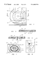
- FIG. 1 is a top perspective view of the invention.
- FIG. 2 is a bottom plan view of the invention.
- FIG. 3 is an expanded perspective view of the invention being placed in a disc tray.
- FIG. 4 is a top plan view of the invention within a disc tray.
- FIG. 5 is a sectional view of the invention within a disc tray.
- FIG. 6 is a sectional view of the invention within a disc tray and a spindle.
- FIG. 7 is a bottom perspective view of the invention with a docking collar.
- FIG. 8 is the invention with an image embossed on the top surface.
- FIG. 9 is a expanded perspective view of a second embodiment of the invention.
- the present invention is depicted in FIGS. 1 through 9 and includes a compact disc 11 (also referred to as “CD”) that has been reduced in size to replicate a trading card.
- the compact disc 11 includes a planar body having a top surface 16 and a bottom surface 17 .
- the planar body has a rectangular shape including two end edges 25 and two side edges 26 .
- a spindle hole 12 is centrally aligned on the CD 11 .
- This centrally located hole 12 supports the compact disc 11 on a spindle enabling it to rotate for optical reading by standard CD or CD-ROM player optical readout devices.
- the compact disc is made of a plastic or any other hard, durable transparent material, manufactured through an injection molding process. The placement and manufacture of the optically readable data is performed by utilizing traditional CD manufacturing processes.
- the CD 11 includes a means for aligning the disc 11 within the tray 18 .
- Two ridges 15 are mounted to the bottom surface 17 of the compact disc 11 . The two ridges 15 facilitate alignment of the compact disc 11 within a CD tray 18 .
- a standard CD tray includes an outer rim 19 and an inner rim 20 .
- the outer rim 19 aligns a standard CD within the tray 18 .
- the inner rim 20 is usually for the alignment of mini-compact discs.
- the compact disc 11 is not as large as a standard CD, and is not capable of engaging the outer rim 19 of the CD tray 18 .
- the ridges 15 are positioned on the compact disc 11 for alignment with the inner rim 20 of the tray 18 . As shown in FIG. 3, the ridges 15 have an arcuate shape concentric with the inner rim 20 of the tray 18 . The ridges 15 are spaced sufficiently from the spindle hole 11 for alignment with the inner rim 20 .
- the optically readable data is located on the bottom surface 17 of the compact disc 11 , as depicted in FIG. 2 . Since the surface of the card itself is made of transparent material, a standard CD or CD-ROM player optical readout device is capable of reading the video/audio/alphabetic programs contained on the compact disc.
- the width of the CD 11 presently enables an outer band 21 of optical data to extend radially outward from the center approximately 1.125 inches.
- An inner band 22 extends radially from the spindle hole 0.875 inches, which utilizing present technology, permits the placement of approximately 60 megabytes of data onto the card's surface.
- a compact disc 11 in the shape of a trading card is about 3.5 inches long and 2.5 inches wide.
- the compact disc 11 is shown in a disc tray 18 in FIG. 6 with a spindle 23 extending through the spindle hole 12 . Some trays have a spindle that extends upward from the tray 18 . With respect to FIGS. 7 and 8, the CD 11 may also have a docking collar 24 mounted on the bottom surface of the CD 11 between the spindle hole 12 and the ridges 15 . When the CD is placed in a disc tray 18 and the tray is activated a spindle rises and extends through the spindle hole 12 . The collar 24 aligns the spindle 23 with the spindle hole 12 when the spindle 23 is activated. In addition the collar 24 supports the planar body of the CD to prevent warping of the disc 11 . The collar 24 has a surface 25 inclined toward the spindle hole 12 forming a conical shape to the docking collar 24 .
- the compact disc 11 may be constructed in a variety of shapes.
- the CD 11 depicted herein has a rectangular shape similar to trading cards.
- the CD trading card 31 has an image 32 embossed thereon and data pertaining to the image 32 is stored on the CD trading card 31 . Audio and/or video information relating to the image 32 on the CD trading card 31 relayed and displayed.
- the compact disc 11 is in the shape of a trading card.
- the CD trading card 11 is aligned within the disc tray 18 by an alignment disc 27 .
- the alignment disc 27 includes a standard compact disc having a depression 28 is centrally located on the alignment disc 27 .
- the depression 28 extends through the alignment disc 27 and a tab 29 extends diagonally across each corner of the depression 27 to support the CD trading card 11 on the alignment disc 27 .
- the edge 30 of the alignment disc 11 is aligned with the outer rim 19 of the disc tray 11 .
- the CD trading card 11 is placed within the alignment disc 27 and is ready to be played.
Abstract
Description
Claims (10)
Priority Applications (1)
| Application Number | Priority Date | Filing Date | Title |
|---|---|---|---|
| US08/990,517 US6400675B1 (en) | 1997-05-15 | 1997-12-12 | Compact disc with a disc tray alignment means |
Applications Claiming Priority (2)
| Application Number | Priority Date | Filing Date | Title |
|---|---|---|---|
| US08/856,915 US5982736A (en) | 1997-05-15 | 1997-05-15 | Trading card optical compact disc and methods of using and forming same |
| US08/990,517 US6400675B1 (en) | 1997-05-15 | 1997-12-12 | Compact disc with a disc tray alignment means |
Related Parent Applications (1)
| Application Number | Title | Priority Date | Filing Date |
|---|---|---|---|
| US08/856,915 Continuation-In-Part US5982736A (en) | 1997-05-15 | 1997-05-15 | Trading card optical compact disc and methods of using and forming same |
Publications (1)
| Publication Number | Publication Date |
|---|---|
| US6400675B1 true US6400675B1 (en) | 2002-06-04 |
Family
ID=46276201
Family Applications (1)
| Application Number | Title | Priority Date | Filing Date |
|---|---|---|---|
| US08/990,517 Expired - Fee Related US6400675B1 (en) | 1997-05-15 | 1997-12-12 | Compact disc with a disc tray alignment means |
Country Status (1)
| Country | Link |
|---|---|
| US (1) | US6400675B1 (en) |
Cited By (19)
| Publication number | Priority date | Publication date | Assignee | Title |
|---|---|---|---|---|
| US20020170958A1 (en) * | 2001-05-15 | 2002-11-21 | Masih Madani | Computer readable universal authorization card system and method for using same |
| US20030152017A1 (en) * | 2000-03-24 | 2003-08-14 | Tomoaki Ito | Optical disc |
| US20030155425A1 (en) * | 2000-02-11 | 2003-08-21 | Lynch Jeffrey Thomas | CD smartcard |
| US20040050939A1 (en) * | 2000-03-17 | 2004-03-18 | Arne Mathias | Optical business card |
| US20040056102A1 (en) * | 2002-09-20 | 2004-03-25 | Yau Sheung Cheung | Multi-Purpose disc |
| US6754165B2 (en) * | 2002-01-25 | 2004-06-22 | Robert C. Burnett | Diameter reducible, multiple part optical disk |
| US6760280B1 (en) * | 1999-07-10 | 2004-07-06 | Karl-Heinz Schoppe | Optical memory card in the form of a disk |
| US20040133778A1 (en) * | 2003-01-07 | 2004-07-08 | Masih Madani | Virtual pad |
| US20040172645A1 (en) * | 2001-04-24 | 2004-09-02 | Chan Chak Sang Simon | Optically readable information disc |
| US20050268315A1 (en) * | 2002-07-30 | 2005-12-01 | Yoshito Saji | Disc cartridge |
| US20060118618A1 (en) * | 2004-12-06 | 2006-06-08 | Target Brands, Inc. | Stored-value card adapted to be read by an electronic device |
| US20070190861A1 (en) * | 2004-02-17 | 2007-08-16 | R&R Card Systems, Inc. | Interactive multimedia smart affinity card |
| US20070240178A1 (en) * | 2006-04-07 | 2007-10-11 | Kleker Richard G | Apparatus and method for storing digital data |
| US20080078832A1 (en) * | 2006-10-03 | 2008-04-03 | Target Brands, Inc. | Finger puppet stored-value card |
| US20090112761A1 (en) * | 2007-10-31 | 2009-04-30 | Target Brands, Inc. | Transaction product with memory |
| US20090236430A1 (en) * | 2004-02-17 | 2009-09-24 | R & R Card Systems, Inc. | Interactive multimedia smart affinity card with flash memory |
| US7810735B2 (en) | 2001-05-15 | 2010-10-12 | Inadam Corporation | Computer readable universal authorization card system and method for using same |
| US8403228B2 (en) | 2001-05-15 | 2013-03-26 | Inadam Corporation | Computer readable universal authorization card system and method for using same |
| USD734341S1 (en) * | 2012-08-06 | 2015-07-14 | Panasonic Intellectual Property Management Co., Ltd. | Optical disk |
Citations (14)
| Publication number | Priority date | Publication date | Assignee | Title |
|---|---|---|---|---|
| US3201133A (en) * | 1962-05-07 | 1965-08-17 | Matsukata Kosuke | Record changer diameter adapter |
| US4166622A (en) * | 1978-02-13 | 1979-09-04 | Rager Edgar A | Centering collar for a disk hub |
| US4634617A (en) * | 1983-08-18 | 1987-01-06 | Sharp Kabushiki Kaisha | Optical memory disc |
| US4812633A (en) * | 1988-04-08 | 1989-03-14 | Minnesota Mining And Manufacturing Company | Optical data card |
| US4899330A (en) * | 1987-09-16 | 1990-02-06 | U.S. Philips Corporation | Adaptor for mini CD |
| US4916687A (en) * | 1986-05-13 | 1990-04-10 | Canon Kabushiki Kaisha | Apparatus for mounting and rotating an optical card for recording and/or reproducing information |
| US4928271A (en) * | 1987-06-10 | 1990-05-22 | U.S. Philips Corporation | Holder for discs of different diameters |
| US5003530A (en) * | 1987-03-14 | 1991-03-26 | Sony Corporation | Apparatus for adapting the diameter of a disk-like recording medium |
| JPH0440586A (en) * | 1990-06-07 | 1992-02-10 | Nippon Telegr & Teleph Corp <Ntt> | Information card |
| US5105414A (en) * | 1987-11-06 | 1992-04-14 | Tadashi Funabashi | Information recording disk playback apparatus |
| US5579296A (en) * | 1995-01-18 | 1996-11-26 | Cyberwerks Interactive, L.L.C. | Optically readable thin film digital data storage medium |
| US5982736A (en) * | 1997-05-15 | 1999-11-09 | Pierson; Gerald A. | Trading card optical compact disc and methods of using and forming same |
| US6016298A (en) | 1997-06-25 | 2000-01-18 | Adivan High Tech Ag | Calling card |
| USD435853S1 (en) * | 1998-11-06 | 2001-01-02 | Spike Interactive LLC | CD card |
-
1997
- 1997-12-12 US US08/990,517 patent/US6400675B1/en not_active Expired - Fee Related
Patent Citations (15)
| Publication number | Priority date | Publication date | Assignee | Title |
|---|---|---|---|---|
| US3201133A (en) * | 1962-05-07 | 1965-08-17 | Matsukata Kosuke | Record changer diameter adapter |
| US4166622A (en) * | 1978-02-13 | 1979-09-04 | Rager Edgar A | Centering collar for a disk hub |
| US4634617A (en) * | 1983-08-18 | 1987-01-06 | Sharp Kabushiki Kaisha | Optical memory disc |
| US4916687A (en) * | 1986-05-13 | 1990-04-10 | Canon Kabushiki Kaisha | Apparatus for mounting and rotating an optical card for recording and/or reproducing information |
| US5003530A (en) * | 1987-03-14 | 1991-03-26 | Sony Corporation | Apparatus for adapting the diameter of a disk-like recording medium |
| US4928271A (en) * | 1987-06-10 | 1990-05-22 | U.S. Philips Corporation | Holder for discs of different diameters |
| US4899330A (en) * | 1987-09-16 | 1990-02-06 | U.S. Philips Corporation | Adaptor for mini CD |
| US5105414A (en) * | 1987-11-06 | 1992-04-14 | Tadashi Funabashi | Information recording disk playback apparatus |
| US4812633A (en) * | 1988-04-08 | 1989-03-14 | Minnesota Mining And Manufacturing Company | Optical data card |
| JPH0440586A (en) * | 1990-06-07 | 1992-02-10 | Nippon Telegr & Teleph Corp <Ntt> | Information card |
| US5579296A (en) * | 1995-01-18 | 1996-11-26 | Cyberwerks Interactive, L.L.C. | Optically readable thin film digital data storage medium |
| US5982736A (en) * | 1997-05-15 | 1999-11-09 | Pierson; Gerald A. | Trading card optical compact disc and methods of using and forming same |
| US6078557A (en) * | 1997-05-15 | 2000-06-20 | Pierson; Gerald A. | Method of using optical compact disc |
| US6016298A (en) | 1997-06-25 | 2000-01-18 | Adivan High Tech Ag | Calling card |
| USD435853S1 (en) * | 1998-11-06 | 2001-01-02 | Spike Interactive LLC | CD card |
Cited By (30)
| Publication number | Priority date | Publication date | Assignee | Title |
|---|---|---|---|---|
| US6760280B1 (en) * | 1999-07-10 | 2004-07-06 | Karl-Heinz Schoppe | Optical memory card in the form of a disk |
| US20030155425A1 (en) * | 2000-02-11 | 2003-08-21 | Lynch Jeffrey Thomas | CD smartcard |
| US20040050939A1 (en) * | 2000-03-17 | 2004-03-18 | Arne Mathias | Optical business card |
| US6857575B2 (en) * | 2000-03-17 | 2005-02-22 | Fuji Magnetics Gmbh | Optical business card |
| US20030152017A1 (en) * | 2000-03-24 | 2003-08-14 | Tomoaki Ito | Optical disc |
| US6948182B2 (en) * | 2000-03-24 | 2005-09-20 | Tomoaki Ito | Optical disc |
| US20040172645A1 (en) * | 2001-04-24 | 2004-09-02 | Chan Chak Sang Simon | Optically readable information disc |
| US8403228B2 (en) | 2001-05-15 | 2013-03-26 | Inadam Corporation | Computer readable universal authorization card system and method for using same |
| US20020170958A1 (en) * | 2001-05-15 | 2002-11-21 | Masih Madani | Computer readable universal authorization card system and method for using same |
| US7299980B2 (en) | 2001-05-15 | 2007-11-27 | Inadam Corporation | Computer readable universal authorization card system and method for using same |
| US7810735B2 (en) | 2001-05-15 | 2010-10-12 | Inadam Corporation | Computer readable universal authorization card system and method for using same |
| US6754165B2 (en) * | 2002-01-25 | 2004-06-22 | Robert C. Burnett | Diameter reducible, multiple part optical disk |
| US20050268315A1 (en) * | 2002-07-30 | 2005-12-01 | Yoshito Saji | Disc cartridge |
| US20040056102A1 (en) * | 2002-09-20 | 2004-03-25 | Yau Sheung Cheung | Multi-Purpose disc |
| US20040133778A1 (en) * | 2003-01-07 | 2004-07-08 | Masih Madani | Virtual pad |
| US7735121B2 (en) | 2003-01-07 | 2010-06-08 | Masih Madani | Virtual pad |
| US8370637B2 (en) | 2003-01-07 | 2013-02-05 | Masih Madani | Virtual pad |
| US20110072259A1 (en) * | 2003-01-07 | 2011-03-24 | Masih Madani | Virtual pad |
| US20070190861A1 (en) * | 2004-02-17 | 2007-08-16 | R&R Card Systems, Inc. | Interactive multimedia smart affinity card |
| US7540412B2 (en) * | 2004-02-17 | 2009-06-02 | R & R Card Systems | Interactive multimedia smart affinity card |
| US20090236430A1 (en) * | 2004-02-17 | 2009-09-24 | R & R Card Systems, Inc. | Interactive multimedia smart affinity card with flash memory |
| US8177129B2 (en) | 2004-02-17 | 2012-05-15 | Timothy D. Larin | Interactive multimedia smart affinity card with flash memory |
| US7252225B2 (en) | 2004-12-06 | 2007-08-07 | Target Brands, Inc. | Stored-value card adapted to be read by an electronic device |
| US20060118618A1 (en) * | 2004-12-06 | 2006-06-08 | Target Brands, Inc. | Stored-value card adapted to be read by an electronic device |
| US20070240178A1 (en) * | 2006-04-07 | 2007-10-11 | Kleker Richard G | Apparatus and method for storing digital data |
| US7717335B2 (en) | 2006-10-03 | 2010-05-18 | Target Brands, Inc. | Finger puppet stored-value card |
| US20080078832A1 (en) * | 2006-10-03 | 2008-04-03 | Target Brands, Inc. | Finger puppet stored-value card |
| US20090112761A1 (en) * | 2007-10-31 | 2009-04-30 | Target Brands, Inc. | Transaction product with memory |
| US7841538B2 (en) | 2007-10-31 | 2010-11-30 | Target Brands, Inc. | Transaction product with memory |
| USD734341S1 (en) * | 2012-08-06 | 2015-07-14 | Panasonic Intellectual Property Management Co., Ltd. | Optical disk |
Similar Documents
| Publication | Publication Date | Title |
|---|---|---|
| US6400675B1 (en) | Compact disc with a disc tray alignment means | |
| US7308696B2 (en) | Data storage apparatus | |
| JP3394264B2 (en) | Business card type information recording card | |
| US4736840A (en) | Protective holder for a compact disc or the like | |
| US20020167890A2 (en) | Storage card | |
| JPH05189929A (en) | Compact disk package | |
| US5942165A (en) | Method for making irregular shaped CD's and other playing discs | |
| US5295577A (en) | Storage system for compact discs | |
| US4899330A (en) | Adaptor for mini CD | |
| WO2005013247A1 (en) | Promotional compact disc carrier system | |
| US5848687A (en) | CD protector ring | |
| WO1992006904A1 (en) | Optical storage disc protector | |
| EP0645045B1 (en) | Optical compact disc storage and loading cassette | |
| JP3499856B2 (en) | Adapter for non-round disk | |
| US20040170116A1 (en) | Optical disc incorporating a relief pattern | |
| WO2000052685A1 (en) | Business card in the form of a cd-rom | |
| JP2001338440A (en) | Optical disk | |
| US20030218967A1 (en) | Abrasion-resistant compact disc | |
| JPH0411266Y2 (en) | ||
| JP3564015B2 (en) | Card type information record carrier | |
| WO2007010809A1 (en) | Memory card holder | |
| JPS5827415Y2 (en) | cassette disk | |
| US20030075461A1 (en) | Carriers for compact discs | |
| JP3499846B2 (en) | Adapter for non-circular optical disc | |
| JPS58205967A (en) | Disc containing case |
Legal Events
| Date | Code | Title | Description |
|---|---|---|---|
| AS | Assignment |
Owner name: SPACEMARK INTERNATIONAL CORPORATION, FLORIDA Free format text: ASSIGNMENT OF ASSIGNORS INTEREST;ASSIGNOR:EVERIDGE, BENJAMIN JAMES;REEL/FRAME:008924/0694 Effective date: 19971212 |
|
| AS | Assignment |
Owner name: SPACEMARK INTERNATIONAL CORPORATION, FLORIDA Free format text: ASSIGNMENT OF ASSIGNORS INTEREST;ASSIGNORS:EVERIDGE, BENJAMIN J.;ENGELKING, RAYMOND K.;PIERSON, GERALD A.;REEL/FRAME:011659/0329 Effective date: 20010322 |
|
| REMI | Maintenance fee reminder mailed | ||
| FPAY | Fee payment |
Year of fee payment: 4 |
|
| SULP | Surcharge for late payment | ||
| REMI | Maintenance fee reminder mailed | ||
| LAPS | Lapse for failure to pay maintenance fees | ||
| STCH | Information on status: patent discontinuation |
Free format text: PATENT EXPIRED DUE TO NONPAYMENT OF MAINTENANCE FEES UNDER 37 CFR 1.362 |
|
| FP | Lapsed due to failure to pay maintenance fee |
Effective date: 20100604 |