US6414940B1 - Method and system of managing unidirectional failures in a distributed restoration network - Google Patents
Method and system of managing unidirectional failures in a distributed restoration network Download PDFInfo
- Publication number
- US6414940B1 US6414940B1 US09/046,089 US4608998A US6414940B1 US 6414940 B1 US6414940 B1 US 6414940B1 US 4608998 A US4608998 A US 4608998A US 6414940 B1 US6414940 B1 US 6414940B1
- Authority
- US
- United States
- Prior art keywords
- alarm signal
- node
- signal
- alarm
- network
- Prior art date
- Legal status (The legal status is an assumption and is not a legal conclusion. Google has not performed a legal analysis and makes no representation as to the accuracy of the status listed.)
- Expired - Lifetime
Links
- 238000000034 method Methods 0.000 title claims description 21
- 230000002457 bidirectional effect Effects 0.000 claims abstract description 18
- 230000001902 propagating effect Effects 0.000 claims description 8
- RGNPBRKPHBKNKX-UHFFFAOYSA-N hexaflumuron Chemical compound C1=C(Cl)C(OC(F)(F)C(F)F)=C(Cl)C=C1NC(=O)NC(=O)C1=C(F)C=CC=C1F RGNPBRKPHBKNKX-UHFFFAOYSA-N 0.000 claims description 7
- 102100040338 Ubiquitin-associated and SH3 domain-containing protein B Human genes 0.000 claims 4
- 101710143616 Ubiquitin-associated and SH3 domain-containing protein B Proteins 0.000 claims 4
- 230000000644 propagated effect Effects 0.000 description 8
- 238000006243 chemical reaction Methods 0.000 description 7
- 230000007257 malfunction Effects 0.000 description 5
- 238000001514 detection method Methods 0.000 description 4
- 230000000694 effects Effects 0.000 description 3
- 230000002708 enhancing effect Effects 0.000 description 2
- 239000011159 matrix material Substances 0.000 description 2
- 230000005856 abnormality Effects 0.000 description 1
- 230000005540 biological transmission Effects 0.000 description 1
- 238000004891 communication Methods 0.000 description 1
- 238000012986 modification Methods 0.000 description 1
- 230000004048 modification Effects 0.000 description 1
- 239000013307 optical fiber Substances 0.000 description 1
- 230000002688 persistence Effects 0.000 description 1
- 238000006467 substitution reaction Methods 0.000 description 1
- 230000001360 synchronised effect Effects 0.000 description 1
- 230000001052 transient effect Effects 0.000 description 1
- 238000011144 upstream manufacturing Methods 0.000 description 1
Images


Classifications
-
- H—ELECTRICITY
- H04—ELECTRIC COMMUNICATION TECHNIQUE
- H04L—TRANSMISSION OF DIGITAL INFORMATION, e.g. TELEGRAPHIC COMMUNICATION
- H04L41/00—Arrangements for maintenance, administration or management of data switching networks, e.g. of packet switching networks
- H04L41/12—Discovery or management of network topologies
-
- H—ELECTRICITY
- H04—ELECTRIC COMMUNICATION TECHNIQUE
- H04J—MULTIPLEX COMMUNICATION
- H04J3/00—Time-division multiplex systems
- H04J3/02—Details
- H04J3/14—Monitoring arrangements
-
- H—ELECTRICITY
- H04—ELECTRIC COMMUNICATION TECHNIQUE
- H04L—TRANSMISSION OF DIGITAL INFORMATION, e.g. TELEGRAPHIC COMMUNICATION
- H04L43/00—Arrangements for monitoring or testing data switching networks
- H04L43/08—Monitoring or testing based on specific metrics, e.g. QoS, energy consumption or environmental parameters
- H04L43/0805—Monitoring or testing based on specific metrics, e.g. QoS, energy consumption or environmental parameters by checking availability
- H04L43/0811—Monitoring or testing based on specific metrics, e.g. QoS, energy consumption or environmental parameters by checking availability by checking connectivity
-
- H—ELECTRICITY
- H04—ELECTRIC COMMUNICATION TECHNIQUE
- H04Q—SELECTING
- H04Q3/00—Selecting arrangements
- H04Q3/0016—Arrangements providing connection between exchanges
- H04Q3/0062—Provisions for network management
-
- H—ELECTRICITY
- H04—ELECTRIC COMMUNICATION TECHNIQUE
- H04Q—SELECTING
- H04Q3/00—Selecting arrangements
- H04Q3/0016—Arrangements providing connection between exchanges
- H04Q3/0062—Provisions for network management
- H04Q3/0075—Fault management techniques
- H04Q3/0079—Fault management techniques involving restoration of networks, e.g. disaster recovery, self-healing networks
-
- H—ELECTRICITY
- H04—ELECTRIC COMMUNICATION TECHNIQUE
- H04J—MULTIPLEX COMMUNICATION
- H04J2203/00—Aspects of optical multiplex systems other than those covered by H04J14/05 and H04J14/07
- H04J2203/0001—Provisions for broadband connections in integrated services digital network using frames of the Optical Transport Network [OTN] or using synchronous transfer mode [STM], e.g. SONET, SDH
- H04J2203/0057—Operations, administration and maintenance [OAM]
- H04J2203/006—Fault tolerance and recovery
-
- H—ELECTRICITY
- H04—ELECTRIC COMMUNICATION TECHNIQUE
- H04L—TRANSMISSION OF DIGITAL INFORMATION, e.g. TELEGRAPHIC COMMUNICATION
- H04L41/00—Arrangements for maintenance, administration or management of data switching networks, e.g. of packet switching networks
- H04L41/06—Management of faults, events, alarms or notifications
- H04L41/0654—Management of faults, events, alarms or notifications using network fault recovery
- H04L41/0659—Management of faults, events, alarms or notifications using network fault recovery by isolating or reconfiguring faulty entities
Definitions
- This invention relates to distributed restoration algorithm (DRA) networks, and more particularly to a method and system therefor for determining the location of a fault when only a unidirectional alarm is received.
- DAA distributed restoration algorithm
- DRA distributed restoration algorithm
- a DRA network can be considered to stand on its own as it is connected to other networks.
- Each node, or cross connect switch, in the DRA domain is equipped with an algorithm and associated hardware that allow it to begin to look for a new path for restoring the disrupted traffic when it senses a fault.
- Each of the nodes is interconnected, by means of at least one link or span, to at least one other node.
- the plurality of nodes of a network are interconnected to other nodes by a plurality of links.
- the links via associated equipment, also provide to each node signals that inform the node of the operational status of the network. In other words, signals are provided to each node to inform the node that traffic is being routed among the nodes effectively, or that there has been a malfunction somewhere in the network and that an alternate route or routes are required to reroute the disrupted traffic.
- the conversion of the sensed alarm signal by a pair of adjacent nodes that bracket the fault enables the management of the network to readily identify the location of the fault.
- This signal conversion technique works fine so long as bidirectional alarm signals are generated as a result of the fault. Putting it differently, as long as the pair of custodial nodes each detect an alarm signal resulting from the fault, the location of the fault can be isolated. But in the case where malfunction has occurred to the equipment, for example, that transmits the fault signal to the custodial nodes so that only a unidirectional alarm signal is sent to one of the custodial nodes, this signal conversion technique is at a loss for determining the location of the fault.
- each node of the present invention DRA network Upon receipt of an incoming alarm signal, each node of the present invention DRA network initiates a timer for a predetermined period of time, at the end of which, if the alarm signal is a unidirectional signal from the fault and assuming that the node that has received the alarm signal is one of the two custodial nodes that bracket the fault, it is assumed that the other custodial node should have likewise received the alarm signal.
- the custodial node that received the alarm signal sends a modified alarm signal, which may be in the form of an idle signal with an embedded message that indicates an alarm signal of a unidirectional failure, back along the path from where the alarm signal was received.
- the transmission of the modified alarm signal effectively forces the failure to be bidirectional because it replaces the non-failed signal with the modified alarm signal. If the failure is bidirectional, the modified alarm signal is still sent, but it has no effect because it simply reaches the break/failure point and stops. Upon receipt of the modified alarm signal, the other custodial node, even if it did not receive the alarm signal directly from the fault, recognizes that a fault has occurred and would then, per the aforenoted copending application, convert the modified alarm signal into an idle signal to be propagated to nodes downstream thereof.
- the present invention therefore converts a unidirectional failure into a bidirectional failure so that each node of the custodial pair of nodes that bracket the fault would receive an alarm indicating that a fault has occurred irrespective of whether or not the original alarm from the fault was a unidirectional alarm signal.
- FIG. 1 shows a prior art exemplar distributed restoration network that has encountered a bidirectional failure
- FIG. 2 illustrates the same nodes as shown in the FIG. 1 environment, but in this instance those nodes of the distributed restoration network each are provisioned to convert an incoming alarm signal into a non-alarm signal, and the access/egress nodes of the network are further provisioned to reconvert any received modified alarm signal back into an alarm signal;
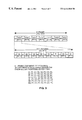
- FIG. 3 shows a frame structure of a Digital Service-3 (DS3) signal for enhancing the understanding of the conversion of an alarm signal into a non-alarm signal in a DS3 format as taught in the aforenoted copending application;
- DS3 Digital Service-3
- FIG. 4 shows the format of a SONET Synchronous Transport Signal (STS-1) frame for enhancing the understanding of the conversion of an alarm signal into a non-alarm signal in a SONET network, as discussed in the aforenoted copending application;
- STS-1 SONET Synchronous Transport Signal
- FIG. 5 illustrates a pair of adjacent nodes and the various signals traversing between those nodes for illustrating the present invention
- FIG. 6 is a flow chart of the operation of the present invention.
- FIG. 7 is a block representation of a node in the distributed restoration network of the instant invention that has been provisioned to convert an alarm into a non-alarm signal, or another alarm signal to be sent to the custodial node that has not received the alarm signal resulting from the fault, and in the case of an access/egress node of the network, to convert a non-alarm signal back into an alarm signal.
- DS3 path that connects node 1 to node 6 of a distributed restoration network is shown.
- an alarm is generated and sent to each of the adjacent nodes.
- Such a fault, or a malfunctioned link is shown to have occurred as a failure between nodes 3 and 4 in FIG. 1 .
- This failure may be due to for example a loss of signal (LOS) or a loss of frame (LOF) in the signal traversing between nodes 3 and 4 .
- LOS loss of signal
- LEF loss of frame
- an alarm signal is an Alarm Indication Signal (AIS).
- each node of the network is provisioned to follow the standards set forth in the Bellcore document TR-NWT-00170 which mandate that each node downstream of the custodial nodes, such as nodes 3 and 4 , upon receipt of an AIS signal, should propagate the signal to nodes downstream thereof.
- node 3 upon receipt of the AIS signal, node 3 propagates the AIS signal to node 2 , which in turn propagates it along the DS3 path to nodes downstream thereof.
- the same flow of the AIS signal received by node 4 occurs with respect to node 4 , node 5 and node 6 .
- node 1 and node 6 each are an access/egress node having access/egress ports for communicatively interconnecting the DRA network to other networks, or other portions of the network not provisioned for distributedly restoring disrupted traffic.
- This modified idle signal is then propagated by the custodial nodes 3 and 4 to respective nodes 2 and 5 downstream thereof.
- Each of nodes 2 and 5 upon receipt of the modified idle signal, would further propagate the same to nodes downstream thereof, such as for example nodes 1 and 6 , respectively.
- each of nodes 1 and 6 is an access/egress node that interconnects the DRA network to other networks.
- the access/egress node For each of those access/egress nodes, when a modified idle signal is received thereat, upon detection that such modified idle signal in fact is not a conventional signal in view of the embedded message, the access/egress node would reconvert the modified idle signal back into an AIS signal, before propagating the AIS signal to nodes outside of the DRA network.
- FIG. 3 shows a DS3 frame structure promulgated under the American National Standard Institute (ANSI) standard T1.107-95.
- ANSI American National Standard Institute
- a DS3 signal is partitioned into M-frames of 4760 bits each.
- Each M-frames is divided into 7 M-subframes each having 680 bits.
- Each M-subframe in turn is further divided into 8 blocks of 85 bits with 84 of the 85 bits available for payload and one bit used for frame overhead.
- M-frame alignment channel M 1 , M 2 , M 3
- F 1 , F 2 , F 3 and F 4 M-subframe alignment channel
- P-bit channel P 1 and P 2
- X-bit channel X 1 and X 2
- C-bit channel C 1 , C 2 and C 3
- C bits C 1 , C 2 , and C 3 which are used for creating the modified alarm signal and the modified idle signal.
- C bits C bits
- the C-bits are set to 0.
- different embedded messages may be effected in the modified alarm signal or modified idle signal.
- the 9 C-bits (C 1 , C 2 and C 3 ) in the M-subframes 2(X 2 ), 6(M 2 ) and 7(M 3 ) of the M-frame may be used.
- the digital cross-connect switch i.e. the node, can convert an incoming signal of one status to an outgoing signal of another status.
- the idle signal that is converted by node 3 from a received AIS signal can have an embedded message, due to changes in the status of the C-bits, to reflect that the modified idle signal is representative of a fault that has already been detected and that it should be further propagated by nodes within the DRA network to other nodes until it reaches an access/egress node. At this point the access/egress node should reconvert such modified idle signal back into a conventional alarm signal before propagating it to nodes outside of the DRA network. As shown in FIG. 2, all operations of each of the nodes of DRA network are monitored by an operations support system (OSS) 10 .
- OSS operations support system
- the signal conversion approach per se, is useful in the case of a bidirectional alarm signal caused by a fault occurring between two custodial nodes. Yet for one reason or another, sometimes when a fault occurs, instead of a bidirectional alarm signal, a unidirectional signal is sent by the equipment that detects the fault to only one of the custodial nodes that bracket the fault. Thus, the reliance on alarm indications reaching both of the custodial nodes that bracket the fault for identifying the location of the fault, fails.
- FIG. 5 provides an illustration of how a unidirectional failure can be converted into a bidirectional failure so that, even if only one of the custodial nodes that bracket a fault detects an alarm signal, such detection nonetheless will lead to the detection of an alarm by both of the custodial nodes so that the location of a fault in a DRA network can be readily identified, per disclosed in the aforenoted copending application.
- the two custodial nodes that bracket the fault X that occurred at a working link 20 are designated nodes A and B.
- a unidirectional alarm signal AIS is sent only to node B.
- no fault has occurred.
- node B even though it has received the AIS signal, it does not know whether its counterpart custodial node A has also received the AIS signal.
- each of nodes A and B is a digital cross-connect switch such as the model 1633 SX made by the Alcatel Company.
- node B Since node B does not know whether node A has received an alarm signal, upon receipt of the AIS signal, it initiates a timer that counts a predetermined period of time to enable node B to confirm that the fault is an actual fault instead of just being a transient abnormality.
- node B converts the AIS signal into a modified idle signal by changing the state of one or more of the C bits so that the modified idle signal has embedded thereto a message that it is a signal that shows an internal failure having occurred in the DRA network.
- This modified idle signal then is propagated to nodes downstream of node B which, upon receipt of it, would propagate it to further downstream nodes until the modified idle signal reaches an access/egress node.
- the access/egress node upon receipt of the modified idle signal, reads from its embedded message that an internal failure has occurred in the DRA network. To ensure that nodes outside of the DRA network are not affected, the access/egress node converts the modified idle signal back into an AIS signal before propagating it to the nodes outside the DRA network.
- node B at the end of the predetermined period of time, sends, by way of the good side of the working link a modified alarm signal to node A.
- This modified alarm signal includes an embedded message that informs node A that a unidirectional failure has been received by node B.
- Node A upon receipt of this modified alarm signal, in addition to recognizing that a fault has occurred, converts this modified alarm signal with the unidirectional failure message into a modified idle signal that indicates that an internal failure has occurred in the DRA network, and further propagates this idle signal to nodes downstream thereof.
- the at issue node makes sure that a fault is indeed a real fault. In other words, oftentimes what appears to be a fault in actuality is but a glitch that disappears shortly and is not an actual fault. A determination is therefore made in decision block 34 on whether or not the alarm remains active. If it is not, the process stops at block 43 . However, if it is, a determination is made on whether the predetermined time has expired per decision block 36 . If it has not, the process loops back to block 34 to again determine whether the alarm remains active. If the timer has indeed expired, then the process progresses to block 38 whereby a modified alarm signal is propagated along the transmit side of the same port where the alarm is indicated.
- this modified alarm signal in effect is an idle signal with an embedded unidirectional failure message that, to its adjacent custodial node, such as node A, acts as an AIS signal.
- the process then stops, as a unidirectional failure now has been rendered to be equivalent to a bidirectional failure, per block 40 .
- FIG. 7 An exemplar node of the instant invention is illustrated in FIG. 7 .
- a number of transceiver units 42 are connected to a digital cross-connect matrix 44 by way of demultiplexers 46 and multiplexers 48 .
- the transceiver units 42 each are connected to an alarm proccssor 50 , a restoration signal sensor 52 , and a restoration signal generator 54 .
- the alarm processor 50 , restoration signal sensor 52 and restoration signal generator 54 are connected to processor 56 of the node.
- the operation of the cross-connect switch 44 is controlled by a node processor 56 .
- signal transceiver detector 58 determines whether the signal is an alarm signal or other type of signal. If the input signal is a conventional idle signal, such idle signal is passed to digital cross-connect switch 44 and propagated to nodes downstream of the node of the FIG. 7 . If, however, the signal received from signal transceiver detector 58 is an alarm signal such as an AIS signal, alarm processor 50 is alerted and the received signal is routed to frame receive unit 60 . There, the signal is parsed and forwarded to converter 64 where the AIS signal is converted into a non-alarm signal, such as the modified idle signal shown in FIG. 5 and discussed above. For propagation to nodes downstream thereof, the node of FIG. 7 converts the input AIS signal into an idle signal with an embedded internal failure message per converter 64 . This modified idle message is then forwarded to the multiplexer 46 and to the appropriate output port of digital cross-connect matrix 44 for propagation to nodes downstream thereof.
Abstract
Description
Claims (22)
Priority Applications (1)
| Application Number | Priority Date | Filing Date | Title |
|---|---|---|---|
| US09/046,089 US6414940B1 (en) | 1997-03-12 | 1998-03-23 | Method and system of managing unidirectional failures in a distributed restoration network |
Applications Claiming Priority (3)
| Application Number | Priority Date | Filing Date | Title |
|---|---|---|---|
| US4053697P | 1997-03-12 | 1997-03-12 | |
| US09/038,531 US6507561B1 (en) | 1997-03-12 | 1998-03-11 | Telecommunications network distributed restoration method and system |
| US09/046,089 US6414940B1 (en) | 1997-03-12 | 1998-03-23 | Method and system of managing unidirectional failures in a distributed restoration network |
Related Parent Applications (1)
| Application Number | Title | Priority Date | Filing Date |
|---|---|---|---|
| US09/038,531 Continuation US6507561B1 (en) | 1997-03-12 | 1998-03-11 | Telecommunications network distributed restoration method and system |
Publications (1)
| Publication Number | Publication Date |
|---|---|
| US6414940B1 true US6414940B1 (en) | 2002-07-02 |
Family
ID=21911526
Family Applications (3)
| Application Number | Title | Priority Date | Filing Date |
|---|---|---|---|
| US09/038,531 Expired - Lifetime US6507561B1 (en) | 1997-03-12 | 1998-03-11 | Telecommunications network distributed restoration method and system |
| US09/046,089 Expired - Lifetime US6414940B1 (en) | 1997-03-12 | 1998-03-23 | Method and system of managing unidirectional failures in a distributed restoration network |
| US09/185,190 Expired - Lifetime US6512740B1 (en) | 1997-03-12 | 1998-11-03 | Telecommunications network distributed restoration method and system |
Family Applications Before (1)
| Application Number | Title | Priority Date | Filing Date |
|---|---|---|---|
| US09/038,531 Expired - Lifetime US6507561B1 (en) | 1997-03-12 | 1998-03-11 | Telecommunications network distributed restoration method and system |
Family Applications After (1)
| Application Number | Title | Priority Date | Filing Date |
|---|---|---|---|
| US09/185,190 Expired - Lifetime US6512740B1 (en) | 1997-03-12 | 1998-11-03 | Telecommunications network distributed restoration method and system |
Country Status (6)
| Country | Link |
|---|---|
| US (3) | US6507561B1 (en) |
| EP (1) | EP0972410B1 (en) |
| AT (1) | ATE341903T1 (en) |
| CA (1) | CA2284184A1 (en) |
| DE (1) | DE69836073T2 (en) |
| WO (1) | WO1998041041A1 (en) |
Cited By (10)
| Publication number | Priority date | Publication date | Assignee | Title |
|---|---|---|---|---|
| WO2002069540A2 (en) * | 2000-11-07 | 2002-09-06 | Oni Systems Corp. | Method and system for a bi-directional path switched network |
| US6717958B1 (en) * | 1998-10-29 | 2004-04-06 | Lg Information & Communication, Ltd. | Video data transmitting/receiving apparatus and method for transmitting video data in a frame structure |
| US20040114526A1 (en) * | 2001-01-16 | 2004-06-17 | Barker Andrew James | Alarm signal suppression in telecommunications networks |
| US20040120706A1 (en) * | 2002-12-20 | 2004-06-24 | Kerry Johnson | Fault isolation in agile transparent networks |
| US6813240B1 (en) | 1999-06-11 | 2004-11-02 | Mci, Inc. | Method of identifying low quality links in a telecommunications network |
| US20070237521A1 (en) * | 2006-03-30 | 2007-10-11 | Lucent Technologies Inc. | Fault isolation and provisioning for optical switches |
| US20080124074A1 (en) * | 2005-06-23 | 2008-05-29 | Yu Yang | Method for handling channel failures in an automatically switched optical network |
| US20110161741A1 (en) * | 2009-12-28 | 2011-06-30 | International Business Machines Corporation | Topology based correlation of threshold crossing alarms |
| US20160182194A1 (en) * | 2014-12-22 | 2016-06-23 | Arista Networks, Inc. | System and method of using undirectional links for tap aggregation |
| US20210176691A1 (en) * | 2013-01-18 | 2021-06-10 | Telefonaktiebolaget Lm Ericsson (Publ) | Adapting a Mobile Network |
Families Citing this family (80)
| Publication number | Priority date | Publication date | Assignee | Title |
|---|---|---|---|---|
| ATE341903T1 (en) | 1997-03-12 | 2006-10-15 | Alcatel Network Syst | METHOD AND SYSTEM FOR DISTRIBUTED RECOVERY OF A TELECOMMUNICATION NETWORK |
| US6269452B1 (en) * | 1998-04-27 | 2001-07-31 | Cisco Technology, Inc. | System and method for fault recovery for a two line bi-directional ring network |
| US6856627B2 (en) * | 1999-01-15 | 2005-02-15 | Cisco Technology, Inc. | Method for routing information over a network |
| US6801496B1 (en) * | 1999-01-15 | 2004-10-05 | Cisco Technology, Inc. | Network addressing scheme for reducing protocol overhead in an optical network |
| US6535481B1 (en) * | 1999-08-20 | 2003-03-18 | Nortel Networks Limited | Network data routing protection cycles for automatic protection switching |
| US6987759B1 (en) * | 1999-10-06 | 2006-01-17 | Cisco Technology, Inc. | Method for using a pre-configured TDM switch and traffic discard to facilitate UPSR selection |
| US6549513B1 (en) | 1999-10-12 | 2003-04-15 | Alcatel | Method and apparatus for fast distributed restoration of a communication network |
| US6813241B1 (en) * | 1999-12-18 | 2004-11-02 | Nortel Networks Limited | Network architecture and method of providing link protection in a bidirectional data traffic network |
| JP2003520525A (en) * | 2000-01-07 | 2003-07-02 | アルカテル | Distributed restoration method and system for communication network |
| US6735215B1 (en) * | 2000-03-11 | 2004-05-11 | Lucent Technologies Inc. | Apparatus and method for automatic port identity discovery in heterogenous systems |
| US6810016B1 (en) * | 2000-05-05 | 2004-10-26 | Cisco Technology, Inc. | Trunking alarm aggregation method and apparatus |
| US6754843B1 (en) * | 2000-06-13 | 2004-06-22 | At&T Corp. | IP backbone network reliability and performance analysis method and apparatus |
| US20020004843A1 (en) * | 2000-07-05 | 2002-01-10 | Loa Andersson | System, device, and method for bypassing network changes in a routed communication network |
| US6996065B2 (en) * | 2000-07-06 | 2006-02-07 | Lucent Technologies Inc. | Dynamic backup routing of network tunnel paths for local restoration in a packet network |
| JP3578062B2 (en) | 2000-08-09 | 2004-10-20 | 日本電気株式会社 | Communication network design circuit, design method therefor, and recording medium and transmission medium recording control program therefor |
| US7170852B1 (en) * | 2000-09-29 | 2007-01-30 | Cisco Technology, Inc. | Mesh with projection channel access (MPCA) |
| CA2359168A1 (en) * | 2000-10-25 | 2002-04-25 | John Doucette | Design of meta-mesh of chain sub-networks |
| US7065569B2 (en) * | 2001-01-09 | 2006-06-20 | Turin Networks, Inc. | System and method for remote traffic management in a communication network |
| US8103789B1 (en) | 2001-03-01 | 2012-01-24 | Juniper Networks, Inc. | Method and apparatus for computing a backup path using fate sharing information |
| US6895441B1 (en) * | 2001-07-30 | 2005-05-17 | Atrica Ireland Ltd. | Path rerouting mechanism utilizing multiple link bandwidth allocations |
| US6766482B1 (en) | 2001-10-31 | 2004-07-20 | Extreme Networks | Ethernet automatic protection switching |
| US20030088659A1 (en) * | 2001-11-08 | 2003-05-08 | Susarla Hanumantha Rao | System and method for distributed state management |
| US7130905B2 (en) * | 2002-01-10 | 2006-10-31 | Sun Microsystems, Inc. | System and method for coordinating access to data for a distributed application |
| US7130262B1 (en) * | 2002-01-16 | 2006-10-31 | At & T Corp. | Method and apparatus for providing alternative link weights for failed network paths |
| US6691167B2 (en) * | 2002-01-28 | 2004-02-10 | Acterna Llc | Method and apparatus for network problem segment isolation |
| US20030154202A1 (en) * | 2002-02-12 | 2003-08-14 | Darpan Dinker | Distributed data system with process co-location and out -of -process communication |
| US7320035B2 (en) * | 2002-03-01 | 2008-01-15 | Sun Microsystems, Inc. | Object mutation determination for incremental state saves |
| US7370329B2 (en) | 2002-03-01 | 2008-05-06 | Sun Microsystems, Inc. | System and method for state saves in a distributed data system |
| JP2003289325A (en) * | 2002-03-28 | 2003-10-10 | Fujitsu Ltd | Method for designing alternate routing for communication network |
| US20040125745A9 (en) * | 2002-04-09 | 2004-07-01 | Ar Card | Two-stage reconnect system and method |
| US7139925B2 (en) * | 2002-04-29 | 2006-11-21 | Sun Microsystems, Inc. | System and method for dynamic cluster adjustment to node failures in a distributed data system |
| US7450516B1 (en) * | 2002-08-06 | 2008-11-11 | At&T Corp. | Link selection schemes for avoiding channel contention |
| US7239605B2 (en) * | 2002-09-23 | 2007-07-03 | Sun Microsystems, Inc. | Item and method for performing a cluster topology self-healing process in a distributed data system cluster |
| US7206836B2 (en) * | 2002-09-23 | 2007-04-17 | Sun Microsystems, Inc. | System and method for reforming a distributed data system cluster after temporary node failures or restarts |
| US8005979B2 (en) * | 2002-10-28 | 2011-08-23 | Oracle America, Inc. | System and method for uniquely identifying processes and entities in clusters |
| US7164888B2 (en) * | 2002-12-23 | 2007-01-16 | Qwest Communications International Inc. | Systems and methods for analyzing critical circuits and associated telecommunication resources |
| US7324458B2 (en) * | 2003-03-21 | 2008-01-29 | Intel Corporation | Physical layer loopback |
| US7545736B2 (en) * | 2003-03-31 | 2009-06-09 | Alcatel-Lucent Usa Inc. | Restoration path calculation in mesh networks |
| US7606237B2 (en) * | 2003-03-31 | 2009-10-20 | Alcatel-Lucent Usa Inc. | Sharing restoration path bandwidth in mesh networks |
| US7646706B2 (en) * | 2003-03-31 | 2010-01-12 | Alcatel-Lucent Usa Inc. | Restoration time in mesh networks |
| US8296407B2 (en) * | 2003-03-31 | 2012-10-23 | Alcatel Lucent | Calculation, representation, and maintenance of sharing information in mesh networks |
| US7643408B2 (en) | 2003-03-31 | 2010-01-05 | Alcatel-Lucent Usa Inc. | Restoration time in networks |
| US7689693B2 (en) * | 2003-03-31 | 2010-03-30 | Alcatel-Lucent Usa Inc. | Primary/restoration path calculation in mesh networks based on multiple-cost criteria |
| US8867333B2 (en) * | 2003-03-31 | 2014-10-21 | Alcatel Lucent | Restoration path calculation considering shared-risk link groups in mesh networks |
| US8001142B2 (en) | 2003-04-02 | 2011-08-16 | Oracle America, Inc. | Distributed data system with incremental data updates |
| US7178065B2 (en) * | 2003-04-02 | 2007-02-13 | Sun Microsystems, Inc. | System and method for measuring performance with distributed agents |
| US7281050B2 (en) * | 2003-04-08 | 2007-10-09 | Sun Microsystems, Inc. | Distributed token manager with transactional properties |
| US6965309B1 (en) * | 2003-04-08 | 2005-11-15 | At&T Corp. | Alarm data delivery method |
| US20050086555A1 (en) * | 2003-10-20 | 2005-04-21 | David Langridge | Optical communications network |
| US7345994B2 (en) * | 2003-10-20 | 2008-03-18 | Cisco Technology, Inc. | Transparent re-routing of MPLS traffic engineering LSPs within a link bundle |
| US20050226212A1 (en) * | 2004-04-02 | 2005-10-13 | Dziong Zbigniew M | Loop avoidance for recovery paths in mesh networks |
| US8111612B2 (en) * | 2004-04-02 | 2012-02-07 | Alcatel Lucent | Link-based recovery with demand granularity in mesh networks |
| US7782787B2 (en) * | 2004-06-18 | 2010-08-24 | Avaya Inc. | Rapid fault detection and recovery for internet protocol telephony |
| US7325161B1 (en) * | 2004-06-30 | 2008-01-29 | Symantec Operating Corporation | Classification of recovery targets to enable automated protection setup |
| US7715306B2 (en) * | 2004-12-07 | 2010-05-11 | Electronics And Telecommunications Research Institute | Multi-layer restoration method using LCAS |
| US7990846B2 (en) * | 2004-12-30 | 2011-08-02 | Alcatel-Lucent Usa Inc. | Method and apparatus for provisioning a hop limited protection pathway in a network |
| JP4704120B2 (en) * | 2005-06-13 | 2011-06-15 | 富士通株式会社 | Network failure detection apparatus and network failure detection method |
| NL1030493C2 (en) * | 2005-11-22 | 2007-05-23 | Asb Technology B V | Method is for determination of time delay in report of occurrence of communication fault in at least one communication unit to be tested out of number of such interconnected units in network |
| US7793158B2 (en) * | 2007-08-27 | 2010-09-07 | International Business Machines Corporation | Providing reliability of communication between supernodes of a multi-tiered full-graph interconnect architecture |
| US8140731B2 (en) * | 2007-08-27 | 2012-03-20 | International Business Machines Corporation | System for data processing using a multi-tiered full-graph interconnect architecture |
| US7958183B2 (en) * | 2007-08-27 | 2011-06-07 | International Business Machines Corporation | Performing collective operations using software setup and partial software execution at leaf nodes in a multi-tiered full-graph interconnect architecture |
| US7840703B2 (en) * | 2007-08-27 | 2010-11-23 | International Business Machines Corporation | System and method for dynamically supporting indirect routing within a multi-tiered full-graph interconnect architecture |
| US8014387B2 (en) * | 2007-08-27 | 2011-09-06 | International Business Machines Corporation | Providing a fully non-blocking switch in a supernode of a multi-tiered full-graph interconnect architecture |
| US7769892B2 (en) | 2007-08-27 | 2010-08-03 | International Business Machines Corporation | System and method for handling indirect routing of information between supernodes of a multi-tiered full-graph interconnect architecture |
| US8185896B2 (en) * | 2007-08-27 | 2012-05-22 | International Business Machines Corporation | Method for data processing using a multi-tiered full-graph interconnect architecture |
| US7809970B2 (en) | 2007-08-27 | 2010-10-05 | International Business Machines Corporation | System and method for providing a high-speed message passing interface for barrier operations in a multi-tiered full-graph interconnect architecture |
| US7904590B2 (en) * | 2007-08-27 | 2011-03-08 | International Business Machines Corporation | Routing information through a data processing system implementing a multi-tiered full-graph interconnect architecture |
| US8108545B2 (en) * | 2007-08-27 | 2012-01-31 | International Business Machines Corporation | Packet coalescing in virtual channels of a data processing system in a multi-tiered full-graph interconnect architecture |
| US7958182B2 (en) * | 2007-08-27 | 2011-06-07 | International Business Machines Corporation | Providing full hardware support of collective operations in a multi-tiered full-graph interconnect architecture |
| US7822889B2 (en) * | 2007-08-27 | 2010-10-26 | International Business Machines Corporation | Direct/indirect transmission of information using a multi-tiered full-graph interconnect architecture |
| US7769891B2 (en) * | 2007-08-27 | 2010-08-03 | International Business Machines Corporation | System and method for providing multiple redundant direct routes between supernodes of a multi-tiered full-graph interconnect architecture |
| US7827428B2 (en) * | 2007-08-31 | 2010-11-02 | International Business Machines Corporation | System for providing a cluster-wide system clock in a multi-tiered full-graph interconnect architecture |
| US7921316B2 (en) * | 2007-09-11 | 2011-04-05 | International Business Machines Corporation | Cluster-wide system clock in a multi-tiered full-graph interconnect architecture |
| US7779148B2 (en) * | 2008-02-01 | 2010-08-17 | International Business Machines Corporation | Dynamic routing based on information of not responded active source requests quantity received in broadcast heartbeat signal and stored in local data structure for other processor chips |
| US8077602B2 (en) * | 2008-02-01 | 2011-12-13 | International Business Machines Corporation | Performing dynamic request routing based on broadcast queue depths |
| US7944815B2 (en) * | 2008-02-14 | 2011-05-17 | Allied Telesis Holdings K.K. | System and method for network recovery from multiple link failures |
| EP2180636B1 (en) | 2008-10-23 | 2011-12-28 | Alcatel Lucent | Method for signaling a unidirectional failure of a packet-switched link |
| US8214687B2 (en) * | 2009-02-13 | 2012-07-03 | International Business Machines Corporation | Disaster recovery based on journaling events prioritization in information technology environments |
| US8873401B2 (en) | 2010-03-16 | 2014-10-28 | Futurewei Technologies, Inc. | Service prioritization in link state controlled layer two networks |
| US8195989B1 (en) * | 2010-08-20 | 2012-06-05 | Juniper Networks, Inc. | Detection of ethernet link failure |
Citations (65)
| Publication number | Priority date | Publication date | Assignee | Title |
|---|---|---|---|---|
| US4648088A (en) | 1985-08-19 | 1987-03-03 | Rockwell International Corporation | Distributed control time division multiplex ring communication apparatus |
| US4825206A (en) | 1985-11-04 | 1989-04-25 | International Business Machines Corporation | Automatic feedback of network topology data |
| US4853927A (en) | 1986-12-10 | 1989-08-01 | U.S. Philips Corporation | Method and circuit arrangement for decentralized controlled transmission rerouting |
| US4884263A (en) | 1986-01-09 | 1989-11-28 | Nec Corporation | Packet-switched communications network with parallel virtual circuits for re-routing message packets |
| US4956835A (en) | 1987-11-06 | 1990-09-11 | Alberta Telecommunications Research Centre | Method and apparatus for self-restoring and self-provisioning communication networks |
| US5070497A (en) | 1989-02-28 | 1991-12-03 | Alcatel N. V. | Transmission network with switchable network nodes |
| US5146452A (en) | 1990-10-26 | 1992-09-08 | Alcatel Network Systems, Inc. | Method and apparatus for rapidly restoring a communication network |
| US5173689A (en) | 1990-06-25 | 1992-12-22 | Nec Corporation | Self-distributed logical channel node failure restoring system |
| US5189662A (en) | 1989-01-26 | 1993-02-23 | Alcatel N.V. | Transmission network having electronically switchable nodes for switching signal paths and a method of controlling said network |
| US5212475A (en) | 1988-05-18 | 1993-05-18 | Siemens Aktiengesellschaft | Method for generating an alarm inhibit signal |
| US5218601A (en) | 1989-12-22 | 1993-06-08 | Fujitsu Limited | Method for searching for alternate path in communication network |
| US5233600A (en) | 1990-08-06 | 1993-08-03 | Alcatel Network Systems, Inc. | Method and apparatus for identifying a failed span in a network of span interconnected nodes |
| US5235599A (en) | 1989-07-26 | 1993-08-10 | Nec Corporation | Self-healing network with distributed failure restoration capabilities |
| US5319632A (en) | 1992-01-17 | 1994-06-07 | Nec Corporation | Transmission network in which a communication path is automatically restored in accordance with occurrence of a failure in a distributed way |
| US5325366A (en) | 1990-10-18 | 1994-06-28 | Fujitsu Limited | Alarm system for station in a communications system using asynchronous third-digital-stage signal |
| US5435003A (en) | 1993-10-07 | 1995-07-18 | British Telecommunications Public Limited Company | Restoration in communications networks |
| US5455832A (en) | 1993-12-17 | 1995-10-03 | Bell Communications Research, Inc. | Method and system for testing a sonet network element |
| US5479608A (en) | 1992-07-17 | 1995-12-26 | Alcatel Network Systems, Inc. | Group facility protection in a digital telecommunications system |
| US5493273A (en) | 1993-09-28 | 1996-02-20 | The United States Of America As Represented By The Secretary Of The Navy | System for detecting perturbations in an environment using temporal sensor data |
| US5495471A (en) | 1994-03-09 | 1996-02-27 | Mci Communications Corporation | System and method for restoring a telecommunications network based on a two prong approach |
| US5537532A (en) | 1993-10-07 | 1996-07-16 | British Telecommunications Public Limited Company | Restoration in communications networks |
| US5548639A (en) | 1991-10-22 | 1996-08-20 | Fujitsu Limited | Distributed control of telecommunication network for setting up an alternative communication path |
| US5586112A (en) | 1993-12-16 | 1996-12-17 | Nec Corporation | Digital crossconnect system for selecting alternate communication routes in case of a transmission fault |
| WO1996041440A1 (en) | 1995-06-07 | 1996-12-19 | Mci Communications Corporation | Method and system for identifying fault locations in a communications network |
| US5590118A (en) | 1994-08-23 | 1996-12-31 | Alcatel N.V. | Method for rerouting a data stream |
| US5590119A (en) | 1995-08-28 | 1996-12-31 | Mci Communications Corporation | Deterministic selection of an optimal restoration route in a telecommunications network |
| US5598403A (en) | 1994-06-22 | 1997-01-28 | Nec Corporation | Path setting control system in communication network |
| US5623481A (en) | 1995-06-07 | 1997-04-22 | Russ; Will | Automated path verification for SHN-based restoration |
| US5636206A (en) | 1994-05-19 | 1997-06-03 | Fujitsu Limited | System for achieving alarm masking processing |
| US5646936A (en) | 1995-06-22 | 1997-07-08 | Mci Corporation | Knowledge based path set up and spare capacity assignment for distributed network restoration |
| US5657320A (en) | 1995-06-06 | 1997-08-12 | Mci Corporation | Method and system for resolving contention of spare capacity circuits of a telecommunications network |
| US5680326A (en) | 1995-06-22 | 1997-10-21 | Mci Corporation | System and method therefor of estimating optimal spare capacity for a distributed restoration scheme |
| WO1997048189A1 (en) | 1996-06-14 | 1997-12-18 | Mci Communications Corporation | Implementation protocol for shn-based algorithm restoration platform |
| US5710777A (en) | 1992-02-07 | 1998-01-20 | Madge Networks Limited | Communication system |
| US5721727A (en) | 1994-09-29 | 1998-02-24 | Hitachi, Ltd. | Control method and apparatus for path switching in ring network |
| US5734687A (en) | 1992-11-09 | 1998-03-31 | Nokia Telecommunications Oy | Hierarchical synchronization method and a telecommunications system employing message-based synchronization |
| US5748617A (en) | 1996-05-01 | 1998-05-05 | Mci Corporation | Method and apparatus for emulating a digital cross-connect switch network |
| US5748611A (en) | 1996-06-27 | 1998-05-05 | Mci Corporation | System and method for restoring a telecommunications network using conservative bandwidth reservation and selective message rebroadcast |
| US5757774A (en) | 1994-03-18 | 1998-05-26 | Fujitsu Limited | Network traffic protection system |
| US5802144A (en) | 1996-04-15 | 1998-09-01 | Mci Corporation | Minimum common span network outage detection and isolation |
| US5832196A (en) | 1996-06-28 | 1998-11-03 | Mci Communications Corporation | Dynamic restoration process for a telecommunications network |
| US5838660A (en) | 1996-11-14 | 1998-11-17 | Mci Communications Corporation | Dynamic restoration process |
| US5850505A (en) | 1995-10-31 | 1998-12-15 | Telecommunications Research Laboratories | Method for preconfiguring a network to withstand anticipated failures |
| US5852600A (en) * | 1995-06-07 | 1998-12-22 | Mci Communications Corporation | System and method for resolving substantially simultaneous bi-directional requests of spare capacity |
| US5862125A (en) | 1995-06-07 | 1999-01-19 | Mci Communication Corporation | Automated restoration of unrestored link and nodal failures |
| US5862362A (en) | 1995-10-05 | 1999-01-19 | Microsoft Corporation | Network failure simulator |
| US5867689A (en) | 1996-05-01 | 1999-02-02 | Mci Communications Corporation | Method and apparatus for emulating a digital cross-connect switch network using a flexible topology to test MCS network management |
| US5875172A (en) | 1995-05-31 | 1999-02-23 | Nec Corporation | Automatic transmission network restoring system |
| US5933422A (en) | 1996-08-20 | 1999-08-03 | Nec Corporation | Communication network recoverable from link failure using prioritized recovery classes |
| US5943314A (en) | 1996-12-30 | 1999-08-24 | Mci Communications Corporation | Method and system of distributed network restoration with multiple failures |
| US5986783A (en) | 1997-02-10 | 1999-11-16 | Optical Networks, Inc. | Method and apparatus for operation, protection, and restoration of heterogeneous optical communication networks |
| US5991338A (en) | 1996-10-21 | 1999-11-23 | Koninklijke Ptt Nederland N.V. | Pinpointing interruptions |
| US5999286A (en) | 1997-01-09 | 1999-12-07 | Alcatel | Method and system for restoring a distributed telecommunications network |
| US6021113A (en) | 1997-10-29 | 2000-02-01 | Lucent Technologies Inc. | Distributed precomputation of network signal paths with table-based link capacity control |
| US6026073A (en) | 1995-08-07 | 2000-02-15 | British Telecommunications Public Limited Company | Route finding in communications networks |
| US6026077A (en) | 1996-11-08 | 2000-02-15 | Nec Corporation | Failure restoration system suitable for a large-scale network |
| US6044064A (en) * | 1997-03-28 | 2000-03-28 | Mci Communications Corporation | Method and system therefor of confining path verification signals within a distributed restoration network |
| US6049529A (en) * | 1997-03-28 | 2000-04-11 | Mci Communications Corporation | Integration of a path verification message within a signal |
| US6061735A (en) | 1997-10-23 | 2000-05-09 | Mci Communications Corporation | Network restoration plan regeneration responsive to network topology changes |
| US6104695A (en) | 1998-03-31 | 2000-08-15 | Sun Microsystems, Inc. | Repair TTL computation and correction mechanism to perform localized repairs in a multicast data distribution setup/framework |
| US6108309A (en) | 1997-12-08 | 2000-08-22 | Mci Communications Corporation | SONET network element simulator |
| US6137775A (en) | 1997-12-31 | 2000-10-24 | Mci Communications Corporation | Spare capacity planning tool |
| US6154448A (en) | 1997-06-20 | 2000-11-28 | Telefonaktiebolaget Lm Ericsson (Publ) | Next hop loopback |
| US6167025A (en) | 1996-09-11 | 2000-12-26 | Telcordia Technologies, Inc. | Methods and apparatus for restoring connections in an ATM network |
| US6337846B1 (en) | 1998-09-08 | 2002-01-08 | Mci Worldcom, Inc. | Quantification of the quality of spare links in a telecommunications network |
Family Cites Families (4)
| Publication number | Priority date | Publication date | Assignee | Title |
|---|---|---|---|---|
| CA1279734C (en) * | 1987-05-27 | 1991-01-29 | Wayne D. Grover | Method and apparatus for frame-bit modulation and demodulation of ds3signal |
| CA2232507A1 (en) * | 1995-09-22 | 1997-03-27 | Mci Communications Corporation | Communication system and method providing optimal restoration of failed paths |
| US6075766A (en) * | 1996-11-26 | 2000-06-13 | Mci Communications Corporation | Method and apparatus for identifying restoral routes in a network |
| ATE341903T1 (en) | 1997-03-12 | 2006-10-15 | Alcatel Network Syst | METHOD AND SYSTEM FOR DISTRIBUTED RECOVERY OF A TELECOMMUNICATION NETWORK |
-
1998
- 1998-03-11 AT AT98910311T patent/ATE341903T1/en not_active IP Right Cessation
- 1998-03-11 DE DE69836073T patent/DE69836073T2/en not_active Expired - Lifetime
- 1998-03-11 US US09/038,531 patent/US6507561B1/en not_active Expired - Lifetime
- 1998-03-11 EP EP98910311A patent/EP0972410B1/en not_active Expired - Lifetime
- 1998-03-11 WO PCT/US1998/004766 patent/WO1998041041A1/en active IP Right Grant
- 1998-03-11 CA CA002284184A patent/CA2284184A1/en not_active Abandoned
- 1998-03-23 US US09/046,089 patent/US6414940B1/en not_active Expired - Lifetime
- 1998-11-03 US US09/185,190 patent/US6512740B1/en not_active Expired - Lifetime
Patent Citations (69)
| Publication number | Priority date | Publication date | Assignee | Title |
|---|---|---|---|---|
| US4648088A (en) | 1985-08-19 | 1987-03-03 | Rockwell International Corporation | Distributed control time division multiplex ring communication apparatus |
| US4825206A (en) | 1985-11-04 | 1989-04-25 | International Business Machines Corporation | Automatic feedback of network topology data |
| US4884263A (en) | 1986-01-09 | 1989-11-28 | Nec Corporation | Packet-switched communications network with parallel virtual circuits for re-routing message packets |
| US4853927A (en) | 1986-12-10 | 1989-08-01 | U.S. Philips Corporation | Method and circuit arrangement for decentralized controlled transmission rerouting |
| US4956835A (en) | 1987-11-06 | 1990-09-11 | Alberta Telecommunications Research Centre | Method and apparatus for self-restoring and self-provisioning communication networks |
| US5212475A (en) | 1988-05-18 | 1993-05-18 | Siemens Aktiengesellschaft | Method for generating an alarm inhibit signal |
| US5189662A (en) | 1989-01-26 | 1993-02-23 | Alcatel N.V. | Transmission network having electronically switchable nodes for switching signal paths and a method of controlling said network |
| US5070497A (en) | 1989-02-28 | 1991-12-03 | Alcatel N. V. | Transmission network with switchable network nodes |
| US5235599A (en) | 1989-07-26 | 1993-08-10 | Nec Corporation | Self-healing network with distributed failure restoration capabilities |
| US5218601A (en) | 1989-12-22 | 1993-06-08 | Fujitsu Limited | Method for searching for alternate path in communication network |
| US5173689A (en) | 1990-06-25 | 1992-12-22 | Nec Corporation | Self-distributed logical channel node failure restoring system |
| US5233600A (en) | 1990-08-06 | 1993-08-03 | Alcatel Network Systems, Inc. | Method and apparatus for identifying a failed span in a network of span interconnected nodes |
| US5325366A (en) | 1990-10-18 | 1994-06-28 | Fujitsu Limited | Alarm system for station in a communications system using asynchronous third-digital-stage signal |
| US5146452A (en) | 1990-10-26 | 1992-09-08 | Alcatel Network Systems, Inc. | Method and apparatus for rapidly restoring a communication network |
| US5548639A (en) | 1991-10-22 | 1996-08-20 | Fujitsu Limited | Distributed control of telecommunication network for setting up an alternative communication path |
| US5319632A (en) | 1992-01-17 | 1994-06-07 | Nec Corporation | Transmission network in which a communication path is automatically restored in accordance with occurrence of a failure in a distributed way |
| US5710777A (en) | 1992-02-07 | 1998-01-20 | Madge Networks Limited | Communication system |
| US5479608A (en) | 1992-07-17 | 1995-12-26 | Alcatel Network Systems, Inc. | Group facility protection in a digital telecommunications system |
| US5734687A (en) | 1992-11-09 | 1998-03-31 | Nokia Telecommunications Oy | Hierarchical synchronization method and a telecommunications system employing message-based synchronization |
| US5493273A (en) | 1993-09-28 | 1996-02-20 | The United States Of America As Represented By The Secretary Of The Navy | System for detecting perturbations in an environment using temporal sensor data |
| US5537532A (en) | 1993-10-07 | 1996-07-16 | British Telecommunications Public Limited Company | Restoration in communications networks |
| US5435003A (en) | 1993-10-07 | 1995-07-18 | British Telecommunications Public Limited Company | Restoration in communications networks |
| US5586112A (en) | 1993-12-16 | 1996-12-17 | Nec Corporation | Digital crossconnect system for selecting alternate communication routes in case of a transmission fault |
| US5455832A (en) | 1993-12-17 | 1995-10-03 | Bell Communications Research, Inc. | Method and system for testing a sonet network element |
| US5495471A (en) | 1994-03-09 | 1996-02-27 | Mci Communications Corporation | System and method for restoring a telecommunications network based on a two prong approach |
| US5757774A (en) | 1994-03-18 | 1998-05-26 | Fujitsu Limited | Network traffic protection system |
| US5636206A (en) | 1994-05-19 | 1997-06-03 | Fujitsu Limited | System for achieving alarm masking processing |
| US5598403A (en) | 1994-06-22 | 1997-01-28 | Nec Corporation | Path setting control system in communication network |
| US5590118A (en) | 1994-08-23 | 1996-12-31 | Alcatel N.V. | Method for rerouting a data stream |
| US5721727A (en) | 1994-09-29 | 1998-02-24 | Hitachi, Ltd. | Control method and apparatus for path switching in ring network |
| US5875172A (en) | 1995-05-31 | 1999-02-23 | Nec Corporation | Automatic transmission network restoring system |
| US5657320A (en) | 1995-06-06 | 1997-08-12 | Mci Corporation | Method and system for resolving contention of spare capacity circuits of a telecommunications network |
| US5862125A (en) | 1995-06-07 | 1999-01-19 | Mci Communication Corporation | Automated restoration of unrestored link and nodal failures |
| US5841759A (en) | 1995-06-07 | 1998-11-24 | Mci Communications Corporation | Automated path verification for shin-based restoration |
| US5636203A (en) | 1995-06-07 | 1997-06-03 | Mci Corporation | Method and system for identifying fault locations in a communications network |
| WO1996041440A1 (en) | 1995-06-07 | 1996-12-19 | Mci Communications Corporation | Method and system for identifying fault locations in a communications network |
| US5852600A (en) * | 1995-06-07 | 1998-12-22 | Mci Communications Corporation | System and method for resolving substantially simultaneous bi-directional requests of spare capacity |
| US5623481A (en) | 1995-06-07 | 1997-04-22 | Russ; Will | Automated path verification for SHN-based restoration |
| US5646936A (en) | 1995-06-22 | 1997-07-08 | Mci Corporation | Knowledge based path set up and spare capacity assignment for distributed network restoration |
| US5680326A (en) | 1995-06-22 | 1997-10-21 | Mci Corporation | System and method therefor of estimating optimal spare capacity for a distributed restoration scheme |
| US6026073A (en) | 1995-08-07 | 2000-02-15 | British Telecommunications Public Limited Company | Route finding in communications networks |
| US5590119A (en) | 1995-08-28 | 1996-12-31 | Mci Communications Corporation | Deterministic selection of an optimal restoration route in a telecommunications network |
| US5812524A (en) | 1995-08-28 | 1998-09-22 | Mci Communications Corporation | Deterministic selection of an optimal restoration route in a telecommunications network |
| US5862362A (en) | 1995-10-05 | 1999-01-19 | Microsoft Corporation | Network failure simulator |
| US5850505A (en) | 1995-10-31 | 1998-12-15 | Telecommunications Research Laboratories | Method for preconfiguring a network to withstand anticipated failures |
| US5802144A (en) | 1996-04-15 | 1998-09-01 | Mci Corporation | Minimum common span network outage detection and isolation |
| US5748617A (en) | 1996-05-01 | 1998-05-05 | Mci Corporation | Method and apparatus for emulating a digital cross-connect switch network |
| US5867689A (en) | 1996-05-01 | 1999-02-02 | Mci Communications Corporation | Method and apparatus for emulating a digital cross-connect switch network using a flexible topology to test MCS network management |
| WO1997048189A1 (en) | 1996-06-14 | 1997-12-18 | Mci Communications Corporation | Implementation protocol for shn-based algorithm restoration platform |
| US5781535A (en) * | 1996-06-14 | 1998-07-14 | Mci Communications Corp. | Implementation protocol for SHN-based algorithm restoration platform |
| US5748611A (en) | 1996-06-27 | 1998-05-05 | Mci Corporation | System and method for restoring a telecommunications network using conservative bandwidth reservation and selective message rebroadcast |
| US5832196A (en) | 1996-06-28 | 1998-11-03 | Mci Communications Corporation | Dynamic restoration process for a telecommunications network |
| US5933422A (en) | 1996-08-20 | 1999-08-03 | Nec Corporation | Communication network recoverable from link failure using prioritized recovery classes |
| US6167025A (en) | 1996-09-11 | 2000-12-26 | Telcordia Technologies, Inc. | Methods and apparatus for restoring connections in an ATM network |
| US5991338A (en) | 1996-10-21 | 1999-11-23 | Koninklijke Ptt Nederland N.V. | Pinpointing interruptions |
| US6026077A (en) | 1996-11-08 | 2000-02-15 | Nec Corporation | Failure restoration system suitable for a large-scale network |
| US5838660A (en) | 1996-11-14 | 1998-11-17 | Mci Communications Corporation | Dynamic restoration process |
| US5943314A (en) | 1996-12-30 | 1999-08-24 | Mci Communications Corporation | Method and system of distributed network restoration with multiple failures |
| US5999286A (en) | 1997-01-09 | 1999-12-07 | Alcatel | Method and system for restoring a distributed telecommunications network |
| US5986783A (en) | 1997-02-10 | 1999-11-16 | Optical Networks, Inc. | Method and apparatus for operation, protection, and restoration of heterogeneous optical communication networks |
| US6044064A (en) * | 1997-03-28 | 2000-03-28 | Mci Communications Corporation | Method and system therefor of confining path verification signals within a distributed restoration network |
| US6049529A (en) * | 1997-03-28 | 2000-04-11 | Mci Communications Corporation | Integration of a path verification message within a signal |
| US6154448A (en) | 1997-06-20 | 2000-11-28 | Telefonaktiebolaget Lm Ericsson (Publ) | Next hop loopback |
| US6061735A (en) | 1997-10-23 | 2000-05-09 | Mci Communications Corporation | Network restoration plan regeneration responsive to network topology changes |
| US6021113A (en) | 1997-10-29 | 2000-02-01 | Lucent Technologies Inc. | Distributed precomputation of network signal paths with table-based link capacity control |
| US6108309A (en) | 1997-12-08 | 2000-08-22 | Mci Communications Corporation | SONET network element simulator |
| US6137775A (en) | 1997-12-31 | 2000-10-24 | Mci Communications Corporation | Spare capacity planning tool |
| US6104695A (en) | 1998-03-31 | 2000-08-15 | Sun Microsystems, Inc. | Repair TTL computation and correction mechanism to perform localized repairs in a multicast data distribution setup/framework |
| US6337846B1 (en) | 1998-09-08 | 2002-01-08 | Mci Worldcom, Inc. | Quantification of the quality of spare links in a telecommunications network |
Non-Patent Citations (2)
| Title |
|---|
| Bouloutas et al. "Alarm Correlation and Fault Identification in Communication Networks"; 1994 IEEE Transactions and Communications. |
| Manione et al.; "An Inconsistencies Tolerant Approach in the Fault Design of Telecommunications Network"; Feb. 14, 1994. |
Cited By (17)
| Publication number | Priority date | Publication date | Assignee | Title |
|---|---|---|---|---|
| US6717958B1 (en) * | 1998-10-29 | 2004-04-06 | Lg Information & Communication, Ltd. | Video data transmitting/receiving apparatus and method for transmitting video data in a frame structure |
| US6813240B1 (en) | 1999-06-11 | 2004-11-02 | Mci, Inc. | Method of identifying low quality links in a telecommunications network |
| WO2002069540A3 (en) * | 2000-11-07 | 2003-01-16 | Oni Systems Corp | Method and system for a bi-directional path switched network |
| WO2002069540A2 (en) * | 2000-11-07 | 2002-09-06 | Oni Systems Corp. | Method and system for a bi-directional path switched network |
| US7447157B2 (en) * | 2001-01-16 | 2008-11-04 | Ericsson Ab | Alarm signal suppression in telecommunications networks |
| US20040114526A1 (en) * | 2001-01-16 | 2004-06-17 | Barker Andrew James | Alarm signal suppression in telecommunications networks |
| US20040120706A1 (en) * | 2002-12-20 | 2004-06-24 | Kerry Johnson | Fault isolation in agile transparent networks |
| US20080124074A1 (en) * | 2005-06-23 | 2008-05-29 | Yu Yang | Method for handling channel failures in an automatically switched optical network |
| US7773877B2 (en) * | 2005-06-23 | 2010-08-10 | Huawei Technologies Co., Ltd. | Method for handling channel failures in an automatically switched optical network |
| US20070237521A1 (en) * | 2006-03-30 | 2007-10-11 | Lucent Technologies Inc. | Fault isolation and provisioning for optical switches |
| US8849109B2 (en) * | 2006-03-30 | 2014-09-30 | Alcatel Lucent | Fault isolation and provisioning for optical switches |
| US20110161741A1 (en) * | 2009-12-28 | 2011-06-30 | International Business Machines Corporation | Topology based correlation of threshold crossing alarms |
| US8423827B2 (en) * | 2009-12-28 | 2013-04-16 | International Business Machines Corporation | Topology based correlation of threshold crossing alarms |
| US20210176691A1 (en) * | 2013-01-18 | 2021-06-10 | Telefonaktiebolaget Lm Ericsson (Publ) | Adapting a Mobile Network |
| US11570681B2 (en) * | 2013-01-18 | 2023-01-31 | Telefonaktiebolaget Lm Ericsson (Publ) | Adapting a mobile network |
| US20160182194A1 (en) * | 2014-12-22 | 2016-06-23 | Arista Networks, Inc. | System and method of using undirectional links for tap aggregation |
| US10103850B2 (en) * | 2014-12-22 | 2018-10-16 | Arista Networks, Inc. | System and method of using undirectional links for tap aggregation |
Also Published As
| Publication number | Publication date |
|---|---|
| CA2284184A1 (en) | 1998-09-17 |
| US6507561B1 (en) | 2003-01-14 |
| EP0972410B1 (en) | 2006-10-04 |
| EP0972410A1 (en) | 2000-01-19 |
| DE69836073T2 (en) | 2007-05-10 |
| DE69836073D1 (en) | 2006-11-16 |
| US6512740B1 (en) | 2003-01-28 |
| ATE341903T1 (en) | 2006-10-15 |
| WO1998041041A1 (en) | 1998-09-17 |
Similar Documents
| Publication | Publication Date | Title |
|---|---|---|
| US6414940B1 (en) | Method and system of managing unidirectional failures in a distributed restoration network | |
| US5636203A (en) | Method and system for identifying fault locations in a communications network | |
| EP0984574B1 (en) | Backwards-compatible failure restoration in bidirectional multiplex section-switched ring transmission systems | |
| CA2375818C (en) | Transmitter-based path protection switching in a ring network | |
| US6907006B1 (en) | Method and apparatus for detecting faults in IP packet communication | |
| CA2252807C (en) | Bundled protection switching in a wide area network | |
| KR980013135A (en) | Error-free switching in a ring network | |
| EP0827357B1 (en) | Cross-connect network node | |
| US6044064A (en) | Method and system therefor of confining path verification signals within a distributed restoration network | |
| US20040076114A1 (en) | Method and apparatus for shared protection in an optical transport network ring based on the ODU management | |
| JP2000151669A (en) | Communication system | |
| US5587996A (en) | Method of radio-line relief and radio equipment in SDH network | |
| WO1998044666A2 (en) | Integration of a path verification message within a signal | |
| WO1998044666A9 (en) | Integration of a path verification message within a signal | |
| US7289435B2 (en) | Method and system for manifesting alarms in a telecommunication network | |
| EP1014603B1 (en) | Method for detecting and locating a break in a synchronous digital hierarchy (SDH) optical link system | |
| EP1049272B1 (en) | Signal quality monitoring system and method | |
| EP1696639B1 (en) | Failure management and propagation in a telecommunication network | |
| WO1999046941A1 (en) | Backup circuits in a telecommunications network | |
| US6622258B1 (en) | Data protection in a ring network | |
| JP3505406B2 (en) | Ring network system and transmission device | |
| KR100748681B1 (en) | Uni Directional Switching Control Method of Synchronous Digital Hierarchy System | |
| JP2798631B2 (en) | Path switching method for SDH ring network | |
| JP2002164907A (en) | Path route changeover device and path protection method | |
| MXPA97009592A (en) | Method and system to identify defalla locations in a communication network |
Legal Events
| Date | Code | Title | Description |
|---|---|---|---|
| AS | Assignment |
Owner name: MCI COMMUNICATIONS CORPORATION, DISTRICT OF COLUMB Free format text: ASSIGNMENT OF ASSIGNORS INTEREST;ASSIGNORS:SHAH, JASVANTRAI;BENGSTON, LEE;REEL/FRAME:009129/0661;SIGNING DATES FROM 19980308 TO 19980310 |
|
| STCF | Information on status: patent grant |
Free format text: PATENTED CASE |
|
| FPAY | Fee payment |
Year of fee payment: 4 |
|
| FPAY | Fee payment |
Year of fee payment: 8 |
|
| FPAY | Fee payment |
Year of fee payment: 12 |
|
| AS | Assignment |
Owner name: VERIZON PATENT AND LICENSING INC., NEW JERSEY Free format text: ASSIGNMENT OF ASSIGNORS INTEREST;ASSIGNOR:MCI COMMUNICATIONS CORPORATION;REEL/FRAME:032725/0001 Effective date: 20140409 |
|
| AS | Assignment |
Owner name: VERIZON PATENT AND LICENSING INC., NEW JERSEY Free format text: CORRECTIVE ASSIGNMENT TO REMOVE THE PATENT NUMBER 5,835,907 PREVIOUSLY RECORDED ON REEL 032725 FRAME 0001. ASSIGNOR(S) HEREBY CONFIRMS THE ASSIGNMENT;ASSIGNOR:MCI COMMUNICATIONS CORPORATION;REEL/FRAME:033408/0235 Effective date: 20140409 |