US6419699B1 - Universal implant fill connector - Google Patents
Universal implant fill connector Download PDFInfo
- Publication number
- US6419699B1 US6419699B1 US09/291,547 US29154799A US6419699B1 US 6419699 B1 US6419699 B1 US 6419699B1 US 29154799 A US29154799 A US 29154799A US 6419699 B1 US6419699 B1 US 6419699B1
- Authority
- US
- United States
- Prior art keywords
- fill
- barb
- axis
- coupling
- implant
- Prior art date
- Legal status (The legal status is an assumption and is not a legal conclusion. Google has not performed a legal analysis and makes no representation as to the accuracy of the status listed.)
- Expired - Lifetime
Links
Images


Classifications
-
- A—HUMAN NECESSITIES
- A61—MEDICAL OR VETERINARY SCIENCE; HYGIENE
- A61F—FILTERS IMPLANTABLE INTO BLOOD VESSELS; PROSTHESES; DEVICES PROVIDING PATENCY TO, OR PREVENTING COLLAPSING OF, TUBULAR STRUCTURES OF THE BODY, e.g. STENTS; ORTHOPAEDIC, NURSING OR CONTRACEPTIVE DEVICES; FOMENTATION; TREATMENT OR PROTECTION OF EYES OR EARS; BANDAGES, DRESSINGS OR ABSORBENT PADS; FIRST-AID KITS
- A61F2/00—Filters implantable into blood vessels; Prostheses, i.e. artificial substitutes or replacements for parts of the body; Appliances for connecting them with the body; Devices providing patency to, or preventing collapsing of, tubular structures of the body, e.g. stents
- A61F2/02—Prostheses implantable into the body
- A61F2/12—Mammary prostheses and implants
-
- F—MECHANICAL ENGINEERING; LIGHTING; HEATING; WEAPONS; BLASTING
- F16—ENGINEERING ELEMENTS AND UNITS; GENERAL MEASURES FOR PRODUCING AND MAINTAINING EFFECTIVE FUNCTIONING OF MACHINES OR INSTALLATIONS; THERMAL INSULATION IN GENERAL
- F16L—PIPES; JOINTS OR FITTINGS FOR PIPES; SUPPORTS FOR PIPES, CABLES OR PROTECTIVE TUBING; MEANS FOR THERMAL INSULATION IN GENERAL
- F16L27/00—Adjustable joints, Joints allowing movement
- F16L27/02—Universal joints, i.e. with mechanical connection allowing angular movement or adjustment of the axes of the parts in any direction
- F16L27/04—Universal joints, i.e. with mechanical connection allowing angular movement or adjustment of the axes of the parts in any direction with partly spherical engaging surfaces
-
- A—HUMAN NECESSITIES
- A61—MEDICAL OR VETERINARY SCIENCE; HYGIENE
- A61B—DIAGNOSIS; SURGERY; IDENTIFICATION
- A61B17/00—Surgical instruments, devices or methods, e.g. tourniquets
- A61B17/12—Surgical instruments, devices or methods, e.g. tourniquets for ligaturing or otherwise compressing tubular parts of the body, e.g. blood vessels, umbilical cord
- A61B17/132—Tourniquets
- A61B17/1322—Tourniquets comprising a flexible encircling member
-
- A—HUMAN NECESSITIES
- A61—MEDICAL OR VETERINARY SCIENCE; HYGIENE
- A61B—DIAGNOSIS; SURGERY; IDENTIFICATION
- A61B17/00—Surgical instruments, devices or methods, e.g. tourniquets
- A61B2017/00535—Surgical instruments, devices or methods, e.g. tourniquets pneumatically or hydraulically operated
- A61B2017/00557—Surgical instruments, devices or methods, e.g. tourniquets pneumatically or hydraulically operated inflatable
-
- A—HUMAN NECESSITIES
- A61—MEDICAL OR VETERINARY SCIENCE; HYGIENE
- A61B—DIAGNOSIS; SURGERY; IDENTIFICATION
- A61B90/00—Instruments, implements or accessories specially adapted for surgery or diagnosis and not covered by any of the groups A61B1/00 - A61B50/00, e.g. for luxation treatment or for protecting wound edges
- A61B90/02—Devices for expanding tissue, e.g. skin tissue
-
- A—HUMAN NECESSITIES
- A61—MEDICAL OR VETERINARY SCIENCE; HYGIENE
- A61F—FILTERS IMPLANTABLE INTO BLOOD VESSELS; PROSTHESES; DEVICES PROVIDING PATENCY TO, OR PREVENTING COLLAPSING OF, TUBULAR STRUCTURES OF THE BODY, e.g. STENTS; ORTHOPAEDIC, NURSING OR CONTRACEPTIVE DEVICES; FOMENTATION; TREATMENT OR PROTECTION OF EYES OR EARS; BANDAGES, DRESSINGS OR ABSORBENT PADS; FIRST-AID KITS
- A61F2220/00—Fixations or connections for prostheses classified in groups A61F2/00 - A61F2/26 or A61F2/82 or A61F9/00 or A61F11/00 or subgroups thereof
- A61F2220/0008—Fixation appliances for connecting prostheses to the body
-
- Y—GENERAL TAGGING OF NEW TECHNOLOGICAL DEVELOPMENTS; GENERAL TAGGING OF CROSS-SECTIONAL TECHNOLOGIES SPANNING OVER SEVERAL SECTIONS OF THE IPC; TECHNICAL SUBJECTS COVERED BY FORMER USPC CROSS-REFERENCE ART COLLECTIONS [XRACs] AND DIGESTS
- Y10—TECHNICAL SUBJECTS COVERED BY FORMER USPC
- Y10S—TECHNICAL SUBJECTS COVERED BY FORMER USPC CROSS-REFERENCE ART COLLECTIONS [XRACs] AND DIGESTS
- Y10S604/00—Surgery
- Y10S604/905—Aseptic connectors or couplings, e.g. frangible, piercable
Definitions
- the present invention relates to a universal implant fill connector which allows a range of angular motion between the fill tubing and the implant.
- an implant is placed within a body cavity for subsequent inflation and/or deflation with a fluid.
- a breast implant or tissue expander when placed in the dissected pocket, it is typically filled via a fill connector coupled to fill tubing which is attached to a filling material (e.g. saline solution) source.
- a filling material e.g. saline solution
- Another example is bariatric surgery where a gastric balloon or gastric band is implanted in or around the stomach for subsequent inflation.
- fill connectors used to connect the fluid source to the implant, the choice of which often depends on the implant and the particular surgical approach used.
- the first is a permanent attachment of the fill tubing to the implant.
- a common means for this attachment is to make a small opening within the body or shell of the implant and insert the tubing securing it by means of connecting materials such as sleeves, patch assemblies, adhesives or vulcanizing compounds.
- the other two common connectors are for temporary attachment of the fill tubing to the implant by means of a valve in the implant which seals after the fill tubing is removed.
- One of these two temporary attachment means is most commonly used with saline-fill breast implant devices that include a diaphragm valve within the shell.
- the valve has an opening that requires a rigid male implement to be inserted in the opening thus opening the valve and allowing fluid transfer.
- This male implement is the fill tip end of the fill connector, which has on the opposite end one or more barbs which accept the flexible (e.g. silicone or vinyl) fill tubing.
- the fill connector and fill tubing attach to the implant normal to the implant surface.
- the other of the two connectors for temporary fill tubing attachment is designed for a leaf valve which consists of parallel sheets of material forming a channel along the surface of the implant into which a cannula or stylet may be inserted. When this valve is engaged, the fill tubing is generally tangent to the implant surface.
- a surgical approach using either the normal or tangential fill tube orientation is selected before the surgical procedure commences.
- an ad-hoc determination of which approach to use which may be necessary because of unexpected developments that arise prior to or during the surgical procedure, is currently impossible.
- an accurate analysis,of which surgical approach is best suited to a particular patient's particular need is necessary before surgery may proceed.
- Placement of implants in body cavities is usually performed without visual assistance and in small pockets or within dissected tissue planes. Implant orientation with respect to the tubing position and body opening cannot always be ascertained. Complications can arise because of blocked or kinked tubing or premature detachment of the fill tubing from the implant due to excessive tangential and torsional forces on the inflexible connections. Difficulty in filling, improper fill volume, or inability to complete the filling procedure can all delay surgery, require explant, or require surgery to be aborted.
- a fill connector could be modified at its barbed, or leakproof fill tubing connection, end to resolve these intra-operative problems and be universally adaptable for any implant or surgical approach.
- One particular embodiment includes a fill connector with a ball-joint connection having a leak proof fluid pathway therethrough such that the fill tubing may be rotated anywhere from tangential (approximately 0 degrees) to the implant surface up to normal (approximately 90 degrees) to the implant surface.
- the ball-joint connection could also allow for 360 degree rotation of the fill tubing about an axis approximately normal to the implant surface (i.e., in the plane parallel to the surface of the implant).
- An alternative to the ball-joint approach is to use a softer, more flexible material at the barbed end of a typical straight fill connector, while maintaining the standard material (typically polypropylene) at the valve engaging end.
- Yet another alternative embodiment is to design the connector with a bellows having accordion-like pleats and appropriately thinner wall sections to allow ease of bending and repeatable multi-directional flexing.
- FIGS. 1 a and 1 b are is a cross-sectional side view of a ball-joint embodiment of the invention.
- FIGS. 2 a and 2 b are a cross-sectional side view of a modified ball-joint embodiment of the invention which includes a swivel joint which allows 360 degree rotation about an axis approximately normal to the implant surface;
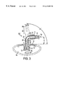
- FIG. 3 is a side view of a flexible-tube embodiment of the invention.
- FIG. 4 is a side view of a bellows embodiment of the invention.
- FIGS. 1 a and 1 b show a fill connector which allows the fill tubing to rotate from a normal position, approximately perpendicular to the implant surface (FIG. 1 a ), to a tangent position, approximately parallel to the implant surface (FIG. 1 b ).
- the fill connector 100 is formed of barb member 1 and fill tip member 2 .
- the socket 3 of barb member 1 is rotatably coupled around pivot 15 to the ball 11 of fill tip member 2 .
- fill tubing 6 is coupled to barb member 1 using a conventional pipe barb 4 .
- the bulb 8 of fill tip member 2 is inserted into diaphragm valve 12 of implant 9 .
- the barb member 1 and fill tip member 2 may be rotated with respect to each other so that the angle ⁇ between the barb axis 4 a of barb 4 and the surface 10 of implant 9 may range from about 0° (approximately tangent as shown in FIG. 1 b ) to about 90° (approximately normal, as shown in FIG. 1 a ).
- the connector 100 may be rotated between a position where barb axis 4 a is approximately perpendicular to the fill tip axis 7 a and a position where barb axis 4 a is approximately parallel to fill tip axis 7 a .
- the dimensions of the connector are such that when ⁇ is approximately 0°, the overall projection of the connector (as measured from and normal to the implant surface 10 ) is minimized, and the outer surface of fill tubing 6 rests upon implant surface 10 .
- Socket passage 13 and ball passage 14 are shaped so that there is a sufficient sealing surface between socket 3 and ball 11 to provide a path that is leak proof at both the negative and positive pressures exerted during the implant fill process.
- the sealing surfaces of the ball 11 and socket 3 as well as the ball passage 14 and socket passage 13 may be designed to allow rotation about the fill tip axis. Furthermore, at pivot 15 , the ball 11 and socket 3 may be provided with indentations and corresponding projections which allow the ball and socket to be lockable at different angles. As an alternative to the embodiment shown in FIGS. 1 a and 1 b , the connector may be designed so that the ball is part of the barb member, and the socket is part of the fill tip member.
- FIGS. 2 a and 2 b show a modification of the fill connector embodiment described above which includes the function and structure of the rotatable ball-and-socket connector described above as well as including additional structure which allows rotation about an axis normal to the implant surface.
- the fill connector 200 is formed of barb member, 1 , swivel member 19 , and fill tip member 16 . Similar to that described above, the socket 3 of barb member 1 is rotatably coupled to the ball 11 of swivel member 19 . During use, fill tubing 6 is coupled to barb member 1 using barb 4 .
- barb refers to any such conventional pipe barb or any appropriate mechanical, chemical, or thermal joint between the :connector and the fill tubing which provides a leakproof connection at both the negative and positive pressures exerted during the implant fill process.
- the bulb 8 of fill tip member 16 is inserted into diaphragm valve 12 of implant 9 .
- the barb member 1 and swivel member 19 may be rotated with respect to each other so that the angle ⁇ between the barb axis 4 a of barb 4 and the surface 10 of implant 9 may range from about 0° (approximately tangent, as shown in FIG. 2 b ) to about 90° (approximately normal, as shown in FIG. 2 a ).
- the connector 200 may be rotated between a position where barb axis 4 a is approximately perpendicular to the fill tube axis 7 a and a position where barb axis 4 a is approximately parallel to the fill tube axis 7 a .
- the swivel member 19 and the fill tip member 16 may be rotated with respect to each other so that the angle ⁇ between the relative positions of the swivel member 19 and the fill tip member 16 , around the fill tip axis 7 a , may have a range of about 360°.
- socket passage 13 and ball passage 14 are shaped so that there is a sufficient sealing surface between socket 3 and ball 11 to provide a leak-proof path.
- swivel member sealing structure 17 and fill tip member sealing structure 18 are shaped to provide a swivel joint that is leak proof at both the negative and positive pressures exerted during the implant fill process. As shown in FIGS.
- the swivel member sealing structure 17 may be a cylindrical indentation which acts as the external rotor of the swivel joint
- fill tip sealing structure 18 may be a cylindrical projection which acts as the internal stator of the swivel joint, or the swivel joint may be implemented so that the rotor and stator are conversely positioned, i.e., the swivel member sealing structure is located within the fill tip member sealing structure.
- FIG. 3 shows a flexible-tube fill connector which allows the fill tubing to be rotated from a tangent position, approximately parallel to the implant surface, to a normal position, approximately perpendicular to the implant surface.
- This embodiment also allows the fill tubing to be rotated about an axis normal to the implant surface.
- the fill connector 300 is formed of barb member 21 and fill tip member 20 .
- Fill tip member 20 is made of a rigid material (e.g., polypropylene), and barb member 21 is made of a softer, more flexible material.
- Fill tip member 20 and barb member 21 are rigidly connected at joint 22 .
- Joint 22 may be made using any appropriate mechanical or thermal process which provides a leak-proof seal at both the negative and positive pressures exerted during the implant fill process.
- fill tubing 6 is coupled to barb member 21 by barb 4 .
- the bulb 8 of fill tip member 20 is inserted into diaphragm valve 12 of implant 9 .
- the barb member 20 and fill tip member 21 may be rotated with respect to each other by flexing tube portion 21 a of barb member 21 so that the angle a between the barb axis 4 a of barb 4 and the surface 10 of implant 9 may range from about 0° (approximately tangent) to about 90° (approximately normal).
- Outline 23 shows the location of barb member 21 and fill tubing 6 when they are rotated into a position where ⁇ is equal to approximately 90°. Consequently, connector 300 may be rotated between a position where barb axis 4 a is approximately perpendicular to fill tip axis 7 a and a position where barb axis 4 a is approximately parallel to fill tip axis 7 a .
- the barb member 20 and fill tip member 21 may be rotated with respect to each other by flexing tube portion 21 a of barb member 21 so that the angle ⁇ between the relative positions of the barb member 21 and the fill tip member 21 , around the fill tip axis 7 a , may have a range of about 360°.
- FIG. 4 shows a bellows fill connector which allows the fill tubing to be rotated from a tangent position, approximately parallel to the implant surface, to a normal position, approximately perpendicular to the implant surface.
- This embodiment also allows rotation of the fill tubing about an axis normal to the implant surface.
- the fill connector 400 is formed of barb member 29 , bellows 25 , and fill tip member 24 .
- Bellows 25 includes a wall thickness 25 a and pleats 25 b which allow repeated multi-directional bending and flexing. Barb member 29 and bellows 25 are connected at joint 28 a , and fill tip member 24 and bellows 25 are connected at joint 28 b .
- Joints 28 a and 28 b may be made using any appropriate mechanical or thermal process which provides a leak-proof seal at both the negative and positive pressures exerted during the implant fill process.
- barb member 29 , bellows 25 , and fill tip member 24 may be a single-piece molding.
- fill tubing 6 is coupled to barb member 29 by barb 4 .
- the bulb 8 of fill tip member 24 is inserted into diaphragm valve 12 of implant 9 .
- the barb member 29 and fill tip member 24 may be rotated with respect to each other by flexing bellows 25 so that the angle ⁇ between the barb axis 4 a of barb 4 and the surface 10 of implant 9 may range from about 0° (approximately tangent) to about 90° (approximately normal).
- Outline 27 shows the location of barb member 29 , bellows 25 , and fill tubing 6 when they are rotated into a position where ⁇ is equal to approximately 90°. Consequently, connector 400 may be rotated between a position where barb axis 4 a is approximately perpendicular to fill tip axis 7 a and a position where barb axis 4 a is approximately parallel to fill tip axis 7 a .
- the barb member 29 and fill tip member 24 may be rotated with respect to each other by flexing bellows 25 so that the angle ⁇ between the relative positions of the barb member 29 and the fill tip member 24 , around the fill tip axis 7 a , may have a range of about 360°.
Abstract
Description
Claims (12)
Priority Applications (13)
| Application Number | Priority Date | Filing Date | Title |
|---|---|---|---|
| US09/291,547 US6419699B1 (en) | 1999-04-14 | 1999-04-14 | Universal implant fill connector |
| EP00926009A EP1238224B9 (en) | 1999-04-14 | 2000-04-14 | Universal implant fill connector |
| PCT/US2000/010142 WO2000061981A1 (en) | 1999-04-14 | 2000-04-14 | Universal implant fill connector |
| ES10183386T ES2422663T3 (en) | 1999-04-14 | 2000-04-14 | Universal implant filler connector |
| DK00926009.2T DK1238224T3 (en) | 1999-04-14 | 2000-04-14 | Universal implant filler connector |
| AT00926009T ATE495403T1 (en) | 1999-04-14 | 2000-04-14 | UNIVERSAL CONNECTING ELEMENT FOR FILLING IMPLANTS |
| MXPA01010335A MXPA01010335A (en) | 1999-04-14 | 2000-04-14 | Universal implant fill connector. |
| AU44611/00A AU4461100A (en) | 1999-04-14 | 2000-04-14 | Universal implant fill connector |
| CA002369035A CA2369035C (en) | 1999-04-14 | 2000-04-14 | Universal implant fill connector |
| ES00926009T ES2357761T3 (en) | 1999-04-14 | 2000-04-14 | UNIVERSAL CONNECTOR FOR THE FILLING OF IMPLANTS. |
| EP10183386.1A EP2287508B1 (en) | 1999-04-14 | 2000-04-14 | Universal implant fill connector |
| JP2000611003A JP4229595B2 (en) | 1999-04-14 | 2000-04-14 | Universal implant fill connector |
| DE60045521T DE60045521D1 (en) | 1999-04-14 | 2000-04-14 | UNIVERSAL CONNECTING ELEMENT FOR FILLING IMPLANTS |
Applications Claiming Priority (1)
| Application Number | Priority Date | Filing Date | Title |
|---|---|---|---|
| US09/291,547 US6419699B1 (en) | 1999-04-14 | 1999-04-14 | Universal implant fill connector |
Publications (1)
| Publication Number | Publication Date |
|---|---|
| US6419699B1 true US6419699B1 (en) | 2002-07-16 |
Family
ID=23120754
Family Applications (1)
| Application Number | Title | Priority Date | Filing Date |
|---|---|---|---|
| US09/291,547 Expired - Lifetime US6419699B1 (en) | 1999-04-14 | 1999-04-14 | Universal implant fill connector |
Country Status (11)
| Country | Link |
|---|---|
| US (1) | US6419699B1 (en) |
| EP (2) | EP1238224B9 (en) |
| JP (1) | JP4229595B2 (en) |
| AT (1) | ATE495403T1 (en) |
| AU (1) | AU4461100A (en) |
| CA (1) | CA2369035C (en) |
| DE (1) | DE60045521D1 (en) |
| DK (1) | DK1238224T3 (en) |
| ES (2) | ES2422663T3 (en) |
| MX (1) | MXPA01010335A (en) |
| WO (1) | WO2000061981A1 (en) |
Cited By (30)
| Publication number | Priority date | Publication date | Assignee | Title |
|---|---|---|---|---|
| US20020022801A1 (en) * | 2000-08-15 | 2002-02-21 | Delegge Rebecca | Gastric access port |
| US20030083518A1 (en) * | 2001-06-27 | 2003-05-01 | Varghese John | Substituted alcohols useful in treatment of Alzheimer's disease |
| US20030120260A1 (en) * | 2001-12-26 | 2003-06-26 | Chu Michael S. H. | Low profile adaptor for use with a medical catheter |
| US20030176852A1 (en) * | 2001-01-05 | 2003-09-18 | Lynch George R | Low profile pivoting joint infusion assembly |
| US20030216686A1 (en) * | 2002-03-08 | 2003-11-20 | Applied Diabetes Research, Inc. | Low profile, pivotal connection infusion assembly |
| US20050147864A1 (en) * | 2003-10-31 | 2005-07-07 | Eggum Shawn D. | Connector assembly for fluid transfer |
| US20060142700A1 (en) * | 2003-06-20 | 2006-06-29 | Sobelman Owen S | Two-way slit valve |
| US7083597B2 (en) | 2001-01-05 | 2006-08-01 | Applied Diabetes Research, Inc. | Pivoting joint infusion system with seal |
| US20060264982A1 (en) * | 2005-05-20 | 2006-11-23 | Viola Frank J | Gastric restrictor assembly and method of use |
| US20060264981A1 (en) * | 2005-05-20 | 2006-11-23 | Viola Frank J | Gastric restrictor assembly and method of use |
| US20060264983A1 (en) * | 2005-05-20 | 2006-11-23 | Henry Holsten | Gastric restrictor assembly and method of use |
| US20070005125A1 (en) * | 2002-04-10 | 2007-01-04 | Boston Scientific Scimed, Inc. | Hybrid stent |
| US20070078393A1 (en) * | 2005-07-12 | 2007-04-05 | Lynch George R | One piece sealing reservoir for an insulin infusion pump |
| US20070129688A1 (en) * | 2004-08-13 | 2007-06-07 | Disetronic Licensing Ag, A Swiss Corporation | Insertion Head for Medical or Pharmaceutical Applications |
| US20080228144A1 (en) * | 2007-03-14 | 2008-09-18 | Diesetronic Licensing Ag | Insertion head for medical or pharmaceutical applications |
| US20080249473A1 (en) * | 2007-03-14 | 2008-10-09 | Diesetronic Licensing Ag | Insertion device for an insertion head, in particular for an infusion set |
| US20080319470A1 (en) * | 2007-06-20 | 2008-12-25 | Viola Frank J | Gastric restrictor assembly and method of use |
| US20090105692A1 (en) * | 2006-05-24 | 2009-04-23 | Ace Development Solution | Male luer lock connector |
| US20090299299A1 (en) * | 2001-01-05 | 2009-12-03 | Lynch George R | Low profile pivoting joint infusion assembly |
| US20100168782A1 (en) * | 2008-12-27 | 2010-07-01 | John Hancock | High specific gravity intragastric device |
| US20100191271A1 (en) * | 2009-01-29 | 2010-07-29 | Lilip Lau | Assembly and method for automatically controlling pressure for a gastric band |
| US20100191265A1 (en) * | 2009-01-29 | 2010-07-29 | Cavu Medical, Inc. | Assembly and method for automatically controlling pressure for a gastric band |
| US20110190704A1 (en) * | 2005-09-21 | 2011-08-04 | Lynch George R | One piece sealing reservoir for an insulin infusion pump |
| US20120179106A1 (en) * | 2003-11-10 | 2012-07-12 | Steve Cote | Subcutaneous infusion device and device for insertion of a cannula of an infusion device and method |
| US20120253367A1 (en) * | 2011-03-29 | 2012-10-04 | Fujifilm Corporation | Vascular anastomosis device |
| USD747184S1 (en) | 2013-03-14 | 2016-01-12 | Hollister Incorporated | Compact catheter package |
| US9463106B2 (en) | 2012-09-10 | 2016-10-11 | Boston Scientific Scimed, Inc. | Catheter with releasable balloon and related methods |
| US20190224037A1 (en) * | 2018-01-19 | 2019-07-25 | Robert Bell | Regulating flow from a stoma on a patient |
| US11229753B2 (en) | 2016-04-29 | 2022-01-25 | Smiths Medical Asd, Inc. | Subcutaneous insertion systems, devices and related methods |
| US20220323251A1 (en) * | 2018-01-19 | 2022-10-13 | Ostovalve Llc | Devices, Systems and Methods for Regulating Flow From a Stoma on a Patient |
Families Citing this family (2)
| Publication number | Priority date | Publication date | Assignee | Title |
|---|---|---|---|---|
| US7887101B2 (en) * | 2007-03-09 | 2011-02-15 | A.S.M. International N.V | Joint for connecting two tubes in a high-temperature environment |
| US8961394B2 (en) | 2011-12-20 | 2015-02-24 | Apollo Endosurgery, Inc. | Self-sealing fluid joint for use with a gastric band |
Citations (19)
| Publication number | Priority date | Publication date | Assignee | Title |
|---|---|---|---|---|
| US2564938A (en) | 1945-05-21 | 1951-08-21 | Charles F Warren | Flexible pipe joint |
| US2890067A (en) | 1954-03-22 | 1959-06-09 | Louis H Morin | Universal lamp swivel connectors |
| US3475039A (en) | 1967-09-18 | 1969-10-28 | Exxon Production Research Co | Universal ball joint for pressurized flow lines |
| US4035004A (en) | 1976-03-18 | 1977-07-12 | Hengesbach Robert W | Ball and socket connector and combination thereof with spray gun |
| US4056116A (en) | 1976-09-08 | 1977-11-01 | Baxter Travenol Laboratories, Inc. | Valve for interconnecting sterile containers and the like |
| US4178643A (en) | 1977-09-26 | 1979-12-18 | Cox James E Jr | Valve for inflatable prosthesis |
| US4427218A (en) | 1980-02-22 | 1984-01-24 | Societe Nationale Elf Aquitaine (Production) | Pressure conduit connecting device |
| US4662396A (en) | 1984-12-28 | 1987-05-05 | Sagiv Mashavei Sadeh | Connector assembly permitting quick attachment and detachment of fluid conduits |
| US4787882A (en) | 1986-01-16 | 1988-11-29 | Gambro Ab | Two stage venous return catheter |
| US4852564A (en) | 1984-06-28 | 1989-08-01 | Sheridan Catheter Corp. | Flexible connectors for medico-surgical tubes |
| US4875718A (en) | 1988-12-02 | 1989-10-24 | Marken Robert E | Swivel connector for preventing kinking of flexible medical hoses |
| US5114033A (en) | 1989-07-21 | 1992-05-19 | Helena Laboratories Corporation | Apparatus for discharging contents of a sealed container |
| US5146933A (en) | 1991-09-20 | 1992-09-15 | Dow Corning Wright Corporation | Implantable prosthetic device and tethered inflation valve for volume |
| US5507536A (en) | 1994-09-09 | 1996-04-16 | Oliveto, Ii; Michael J. | Self sealing insert barb fitting (siblink) |
| US5533983A (en) | 1993-11-26 | 1996-07-09 | Haining; Michael L. | Valved medical connector |
| US5645539A (en) * | 1994-11-14 | 1997-07-08 | Innocare One, Ltd. | Elongated medical channel assembly and method of preventing dislodgement |
| US5651773A (en) * | 1996-01-19 | 1997-07-29 | Perry; Larry C. | Skin protector for ultrasonic-assisted liposuction and accessories |
| US5899944A (en) | 1991-02-28 | 1999-05-04 | Phillips; Van L. | Prosthetic foot incorporating compressible members |
| US5975490A (en) | 1998-01-07 | 1999-11-02 | Essman Screw Products, Inc. | Swivel coupling for hose |
Family Cites Families (2)
| Publication number | Priority date | Publication date | Assignee | Title |
|---|---|---|---|---|
| US4662357A (en) * | 1986-01-21 | 1987-05-05 | Dow Corning Corporation | Inflatable surgical implant with variable inflation position |
| JPH08500274A (en) * | 1993-01-19 | 1996-01-16 | リー ハン−フー, | Device and method for implant prosthesis |
-
1999
- 1999-04-14 US US09/291,547 patent/US6419699B1/en not_active Expired - Lifetime
-
2000
- 2000-04-14 WO PCT/US2000/010142 patent/WO2000061981A1/en active Application Filing
- 2000-04-14 AT AT00926009T patent/ATE495403T1/en not_active IP Right Cessation
- 2000-04-14 ES ES10183386T patent/ES2422663T3/en not_active Expired - Lifetime
- 2000-04-14 AU AU44611/00A patent/AU4461100A/en not_active Abandoned
- 2000-04-14 ES ES00926009T patent/ES2357761T3/en not_active Expired - Lifetime
- 2000-04-14 EP EP00926009A patent/EP1238224B9/en not_active Expired - Lifetime
- 2000-04-14 MX MXPA01010335A patent/MXPA01010335A/en active IP Right Grant
- 2000-04-14 DE DE60045521T patent/DE60045521D1/en not_active Expired - Lifetime
- 2000-04-14 CA CA002369035A patent/CA2369035C/en not_active Expired - Fee Related
- 2000-04-14 DK DK00926009.2T patent/DK1238224T3/en active
- 2000-04-14 EP EP10183386.1A patent/EP2287508B1/en not_active Expired - Lifetime
- 2000-04-14 JP JP2000611003A patent/JP4229595B2/en not_active Expired - Fee Related
Patent Citations (19)
| Publication number | Priority date | Publication date | Assignee | Title |
|---|---|---|---|---|
| US2564938A (en) | 1945-05-21 | 1951-08-21 | Charles F Warren | Flexible pipe joint |
| US2890067A (en) | 1954-03-22 | 1959-06-09 | Louis H Morin | Universal lamp swivel connectors |
| US3475039A (en) | 1967-09-18 | 1969-10-28 | Exxon Production Research Co | Universal ball joint for pressurized flow lines |
| US4035004A (en) | 1976-03-18 | 1977-07-12 | Hengesbach Robert W | Ball and socket connector and combination thereof with spray gun |
| US4056116A (en) | 1976-09-08 | 1977-11-01 | Baxter Travenol Laboratories, Inc. | Valve for interconnecting sterile containers and the like |
| US4178643A (en) | 1977-09-26 | 1979-12-18 | Cox James E Jr | Valve for inflatable prosthesis |
| US4427218A (en) | 1980-02-22 | 1984-01-24 | Societe Nationale Elf Aquitaine (Production) | Pressure conduit connecting device |
| US4852564A (en) | 1984-06-28 | 1989-08-01 | Sheridan Catheter Corp. | Flexible connectors for medico-surgical tubes |
| US4662396A (en) | 1984-12-28 | 1987-05-05 | Sagiv Mashavei Sadeh | Connector assembly permitting quick attachment and detachment of fluid conduits |
| US4787882A (en) | 1986-01-16 | 1988-11-29 | Gambro Ab | Two stage venous return catheter |
| US4875718A (en) | 1988-12-02 | 1989-10-24 | Marken Robert E | Swivel connector for preventing kinking of flexible medical hoses |
| US5114033A (en) | 1989-07-21 | 1992-05-19 | Helena Laboratories Corporation | Apparatus for discharging contents of a sealed container |
| US5899944A (en) | 1991-02-28 | 1999-05-04 | Phillips; Van L. | Prosthetic foot incorporating compressible members |
| US5146933A (en) | 1991-09-20 | 1992-09-15 | Dow Corning Wright Corporation | Implantable prosthetic device and tethered inflation valve for volume |
| US5533983A (en) | 1993-11-26 | 1996-07-09 | Haining; Michael L. | Valved medical connector |
| US5507536A (en) | 1994-09-09 | 1996-04-16 | Oliveto, Ii; Michael J. | Self sealing insert barb fitting (siblink) |
| US5645539A (en) * | 1994-11-14 | 1997-07-08 | Innocare One, Ltd. | Elongated medical channel assembly and method of preventing dislodgement |
| US5651773A (en) * | 1996-01-19 | 1997-07-29 | Perry; Larry C. | Skin protector for ultrasonic-assisted liposuction and accessories |
| US5975490A (en) | 1998-01-07 | 1999-11-02 | Essman Screw Products, Inc. | Swivel coupling for hose |
Cited By (68)
| Publication number | Priority date | Publication date | Assignee | Title |
|---|---|---|---|---|
| US6872189B2 (en) * | 2000-08-15 | 2005-03-29 | Hammerhead Design And Development, Inc. | Gastric access port |
| US20090082736A1 (en) * | 2000-08-15 | 2009-03-26 | Delegge Rebecca | Gastric access port |
| US20020022801A1 (en) * | 2000-08-15 | 2002-02-21 | Delegge Rebecca | Gastric access port |
| AU2001284919B2 (en) * | 2000-08-15 | 2005-12-22 | Hammerhead Design And Development, Inc. | Gastric access port |
| US8043260B2 (en) | 2000-08-15 | 2011-10-25 | Delegge Medical, Inc. | Gastric access port |
| US7569034B2 (en) | 2001-01-05 | 2009-08-04 | Lynch George R | Low profile pivoting joint infusion assembly |
| US20110112481A1 (en) * | 2001-01-05 | 2011-05-12 | Lynch George R | Pivoting joint infusion system with seal |
| US20030176852A1 (en) * | 2001-01-05 | 2003-09-18 | Lynch George R | Low profile pivoting joint infusion assembly |
| US8343115B2 (en) | 2001-01-05 | 2013-01-01 | Applied Diabetes Research, Inc. | Low profile pivoting joint infusion assembly |
| US7083597B2 (en) | 2001-01-05 | 2006-08-01 | Applied Diabetes Research, Inc. | Pivoting joint infusion system with seal |
| US20090299299A1 (en) * | 2001-01-05 | 2009-12-03 | Lynch George R | Low profile pivoting joint infusion assembly |
| US7862545B2 (en) | 2001-01-05 | 2011-01-04 | Applied Diabetes Research, Inc. | Pivoting joint infusion system with steal |
| US9629956B2 (en) * | 2001-01-05 | 2017-04-25 | Vicentra B.V. | Pivoting joint infusion system with seal |
| US8911408B2 (en) * | 2001-01-05 | 2014-12-16 | Applied Diabetes Research, Inc. | Pivoting joint infusion system with seal |
| US20150328401A1 (en) * | 2001-01-05 | 2015-11-19 | Applied Diabetes Research, Inc. | Pivoting joint infusion system with seal |
| US20030083518A1 (en) * | 2001-06-27 | 2003-05-01 | Varghese John | Substituted alcohols useful in treatment of Alzheimer's disease |
| US7766867B2 (en) | 2001-06-29 | 2010-08-03 | Applied Diabetes Research, Inc. | Low profile, pivotal connection infusion assembly |
| US8398586B2 (en) | 2001-06-29 | 2013-03-19 | Applied Diabetes Research Incorporated | Low profile, pivotal connection infusion assembly |
| US6979322B2 (en) | 2001-12-26 | 2005-12-27 | Scimed Life Systems, Inc. | Low profile adaptor for use with a medical catheter |
| US20030120260A1 (en) * | 2001-12-26 | 2003-06-26 | Chu Michael S. H. | Low profile adaptor for use with a medical catheter |
| US20030216686A1 (en) * | 2002-03-08 | 2003-11-20 | Applied Diabetes Research, Inc. | Low profile, pivotal connection infusion assembly |
| US7214207B2 (en) | 2002-03-08 | 2007-05-08 | Applied Diabetes Research, Inc. | Low profile, pivotal connection infusion assembly |
| US20070005125A1 (en) * | 2002-04-10 | 2007-01-04 | Boston Scientific Scimed, Inc. | Hybrid stent |
| US9174033B2 (en) | 2003-06-20 | 2015-11-03 | Apollo Endosurgery, Inc. | Two-way slit valve |
| US20100274194A1 (en) * | 2003-06-20 | 2010-10-28 | Allergan, Inc. | Two-way slit valve |
| US10010440B2 (en) | 2003-06-20 | 2018-07-03 | Apollo Endosurgery Us, Inc. | Intragastric balloon system |
| US10016294B2 (en) | 2003-06-20 | 2018-07-10 | Apollo Endosurgery Us, Inc. | Method of implanting an intragastric balloon |
| US20060142700A1 (en) * | 2003-06-20 | 2006-06-29 | Sobelman Owen S | Two-way slit valve |
| US7749254B2 (en) | 2003-06-20 | 2010-07-06 | Allergan, Inc. | Two-way slit valve |
| US7115335B2 (en) | 2003-10-31 | 2006-10-03 | Entegris, Inc. | Connector assembly for fluid transfer |
| US20050147864A1 (en) * | 2003-10-31 | 2005-07-07 | Eggum Shawn D. | Connector assembly for fluid transfer |
| US20120179106A1 (en) * | 2003-11-10 | 2012-07-12 | Steve Cote | Subcutaneous infusion device and device for insertion of a cannula of an infusion device and method |
| US9192717B2 (en) * | 2003-11-10 | 2015-11-24 | Smiths Medical Asd, Inc. | Subcutaneous infusion device and device for insertion of a cannula of an infusion device and method |
| US20070129688A1 (en) * | 2004-08-13 | 2007-06-07 | Disetronic Licensing Ag, A Swiss Corporation | Insertion Head for Medical or Pharmaceutical Applications |
| US8636697B2 (en) * | 2004-08-13 | 2014-01-28 | Roche Diagnostics International Ag | Insertion head for medical or pharmaceutical applications |
| US8114010B2 (en) | 2005-05-20 | 2012-02-14 | Tyco Healthcare Group Lp | Gastric restrictor assembly and method of use |
| US20060264982A1 (en) * | 2005-05-20 | 2006-11-23 | Viola Frank J | Gastric restrictor assembly and method of use |
| US20060264981A1 (en) * | 2005-05-20 | 2006-11-23 | Viola Frank J | Gastric restrictor assembly and method of use |
| US20060264983A1 (en) * | 2005-05-20 | 2006-11-23 | Henry Holsten | Gastric restrictor assembly and method of use |
| US20100145472A1 (en) * | 2005-05-20 | 2010-06-10 | Tyco Healthcare Group Lp | Gastric Restrictor Assembly And Method Of Use |
| US7691053B2 (en) | 2005-05-20 | 2010-04-06 | Tyco Healthcare Group Lp | Gastric restrictor assembly and method of use |
| US7666180B2 (en) | 2005-05-20 | 2010-02-23 | Tyco Healthcare Group Lp | Gastric restrictor assembly and method of use |
| US8603034B2 (en) | 2005-07-12 | 2013-12-10 | Applied Diabetes Research, Inc. | One piece sealing reservoir for an insulin infusion pump |
| US20070078393A1 (en) * | 2005-07-12 | 2007-04-05 | Lynch George R | One piece sealing reservoir for an insulin infusion pump |
| US20110190704A1 (en) * | 2005-09-21 | 2011-08-04 | Lynch George R | One piece sealing reservoir for an insulin infusion pump |
| US9144645B2 (en) | 2005-09-21 | 2015-09-29 | Applied Diabetes Research, Inc. | One piece sealing reservoir for an insulin infusion pump |
| US8192421B2 (en) * | 2006-05-24 | 2012-06-05 | Ace Development Solution | Male luer lock connector |
| US20090105692A1 (en) * | 2006-05-24 | 2009-04-23 | Ace Development Solution | Male luer lock connector |
| US7815607B2 (en) | 2007-03-14 | 2010-10-19 | Roche Diagnostics International Ag | Insertion device for an insertion head, in particular for an infusion set |
| US20080249473A1 (en) * | 2007-03-14 | 2008-10-09 | Diesetronic Licensing Ag | Insertion device for an insertion head, in particular for an infusion set |
| US7850652B2 (en) | 2007-03-14 | 2010-12-14 | Roche Diagnostics International Ag | Insertion head for medical or pharmaceutical applications |
| US20080228144A1 (en) * | 2007-03-14 | 2008-09-18 | Diesetronic Licensing Ag | Insertion head for medical or pharmaceutical applications |
| US8435203B2 (en) | 2007-06-20 | 2013-05-07 | Covidien Lp | Gastric restrictor assembly and method of use |
| US8790290B2 (en) | 2007-06-20 | 2014-07-29 | Covidien Lp | Gastric restrictor assembly and method of use |
| US20080319470A1 (en) * | 2007-06-20 | 2008-12-25 | Viola Frank J | Gastric restrictor assembly and method of use |
| US8758385B2 (en) | 2008-12-27 | 2014-06-24 | John Hancock | High specific gravity intragastric device |
| US20100168782A1 (en) * | 2008-12-27 | 2010-07-01 | John Hancock | High specific gravity intragastric device |
| US20100312046A1 (en) * | 2009-01-29 | 2010-12-09 | Cavu Medical, Inc. | Assembly and method for automatically controlling pressure for a gastric band |
| US20100191271A1 (en) * | 2009-01-29 | 2010-07-29 | Lilip Lau | Assembly and method for automatically controlling pressure for a gastric band |
| US20100191265A1 (en) * | 2009-01-29 | 2010-07-29 | Cavu Medical, Inc. | Assembly and method for automatically controlling pressure for a gastric band |
| US8845662B2 (en) * | 2011-03-29 | 2014-09-30 | Fujifilm Corporation | Vascular anastomosis device |
| US20120253367A1 (en) * | 2011-03-29 | 2012-10-04 | Fujifilm Corporation | Vascular anastomosis device |
| US9463106B2 (en) | 2012-09-10 | 2016-10-11 | Boston Scientific Scimed, Inc. | Catheter with releasable balloon and related methods |
| USD747184S1 (en) | 2013-03-14 | 2016-01-12 | Hollister Incorporated | Compact catheter package |
| US11229753B2 (en) | 2016-04-29 | 2022-01-25 | Smiths Medical Asd, Inc. | Subcutaneous insertion systems, devices and related methods |
| US20190224037A1 (en) * | 2018-01-19 | 2019-07-25 | Robert Bell | Regulating flow from a stoma on a patient |
| US20220323251A1 (en) * | 2018-01-19 | 2022-10-13 | Ostovalve Llc | Devices, Systems and Methods for Regulating Flow From a Stoma on a Patient |
| US11771585B2 (en) * | 2018-01-19 | 2023-10-03 | Ostovalve, Llc | Devices, systems and methods for regulating flow from a stoma on a patient |
Also Published As
| Publication number | Publication date |
|---|---|
| ES2422663T3 (en) | 2013-09-12 |
| CA2369035C (en) | 2008-11-04 |
| JP4229595B2 (en) | 2009-02-25 |
| EP2287508B1 (en) | 2013-06-12 |
| ATE495403T1 (en) | 2011-01-15 |
| DK1238224T3 (en) | 2011-05-02 |
| MXPA01010335A (en) | 2005-01-17 |
| EP2287508A2 (en) | 2011-02-23 |
| DE60045521D1 (en) | 2011-02-24 |
| EP1238224B9 (en) | 2011-11-09 |
| ES2357761T3 (en) | 2011-04-29 |
| WO2000061981A1 (en) | 2000-10-19 |
| EP2287508A3 (en) | 2012-08-01 |
| JP2002540909A (en) | 2002-12-03 |
| AU4461100A (en) | 2000-11-14 |
| EP1238224A4 (en) | 2007-03-07 |
| EP1238224A1 (en) | 2002-09-11 |
| CA2369035A1 (en) | 2000-10-19 |
| EP1238224B1 (en) | 2011-01-12 |
| ES2357761T9 (en) | 2012-02-14 |
Similar Documents
| Publication | Publication Date | Title |
|---|---|---|
| US6419699B1 (en) | Universal implant fill connector | |
| JP4659333B2 (en) | Improved sealing valve assembly for medical supplies | |
| US7470262B2 (en) | Medical valve | |
| EP1789129B1 (en) | Heart pump connector | |
| US9682224B2 (en) | Method and systems for providing fluid communication with a gastrostomy tube | |
| US5456676A (en) | Rotatable bubble-free connector | |
| US7753338B2 (en) | Luer activated device with minimal fluid displacement | |
| US4662357A (en) | Inflatable surgical implant with variable inflation position | |
| ES2248943T3 (en) | CONNECTOR ELEMENT. | |
| AU2002256970A1 (en) | An improved sealing valve assembly for medical products | |
| JPH11290327A (en) | Trachel mantle with valve | |
| US8876694B2 (en) | Tube connector with a guiding tip | |
| US6415789B1 (en) | Swivel structure | |
| CN102762909B (en) | Device with at least one holow element for conveying a fluid and with a connection element | |
| JPH0542227A (en) | Connecting device for catheter hose | |
| JP2010532232A (en) | Molded and non-divided medical penetrating device | |
| CN114469745A (en) | Stomach tube subassembly |
Legal Events
| Date | Code | Title | Description |
|---|---|---|---|
| AS | Assignment |
Owner name: MCGHAN MEDICAL CORPORATION, CALIFORNIA Free format text: ASSIGNMENT OF ASSIGNORS INTEREST;ASSIGNOR:SCHUESSLER, DAVID J.;REEL/FRAME:012282/0150 Effective date: 20011012 |
|
| STCF | Information on status: patent grant |
Free format text: PATENTED CASE |
|
| AS | Assignment |
Owner name: UNION BANK OF CALIFORNIA, N.A., AS ADMINISTRATIVE Free format text: NOTICE OF GRANT OF SECURITY INTEREST;ASSIGNOR:INAMED MEDICAL PRODUCTS CORPORATION;REEL/FRAME:014007/0442 Effective date: 20030725 |
|
| AS | Assignment |
Owner name: INAMED MEDICAL PRODUCTS CORPORATION, CALIFORNIA Free format text: CHANGE OF NAME;ASSIGNOR:MCGHAN MEDICAL CORPORATION;REEL/FRAME:014022/0567 Effective date: 20011129 |
|
| FPAY | Fee payment |
Year of fee payment: 4 |
|
| AS | Assignment |
Owner name: INAMED MEDICAL PRODUCTS CORPORATION (F/K/A MCGHAN Free format text: TERMINATION OF SECURITY INTEREST;ASSIGNOR:UNION BANK OF CALIFORNIA, N.A., AS ADMINISTRATIVE AGENT;REEL/FRAME:017527/0436 Effective date: 20060310 |
|
| AS | Assignment |
Owner name: ALLERGAN, INC., CALIFORNIA Free format text: ASSIGNMENT OF ASSIGNORS INTEREST;ASSIGNOR:INAMED MEDICAL PRODUCTS CORPORATION;REEL/FRAME:018797/0366 Effective date: 20061212 |
|
| FEPP | Fee payment procedure |
Free format text: PAYOR NUMBER ASSIGNED (ORIGINAL EVENT CODE: ASPN); ENTITY STATUS OF PATENT OWNER: LARGE ENTITY |
|
| FPAY | Fee payment |
Year of fee payment: 8 |
|
| FPAY | Fee payment |
Year of fee payment: 12 |