US6421060B1 - Memory efficient system and method for creating anti-aliased images - Google Patents
Memory efficient system and method for creating anti-aliased images Download PDFInfo
- Publication number
- US6421060B1 US6421060B1 US09/282,813 US28281399A US6421060B1 US 6421060 B1 US6421060 B1 US 6421060B1 US 28281399 A US28281399 A US 28281399A US 6421060 B1 US6421060 B1 US 6421060B1
- Authority
- US
- United States
- Prior art keywords
- image
- recited
- buffer
- pixels
- aliased
- Prior art date
- Legal status (The legal status is an assumption and is not a legal conclusion. Google has not performed a legal analysis and makes no representation as to the accuracy of the status listed.)
- Expired - Lifetime
Links
Images


Classifications
-
- G—PHYSICS
- G06—COMPUTING; CALCULATING OR COUNTING
- G06T—IMAGE DATA PROCESSING OR GENERATION, IN GENERAL
- G06T11/00—2D [Two Dimensional] image generation
- G06T11/001—Texturing; Colouring; Generation of texture or colour
Definitions
- the present invention relates to video images, and more particularly to anti-aliased images provided by a memory efficient system and method.
- a common operation in the field of computer graphics is the creation of an image based on a representation of the boundaries of numerous 2 dimensional (2d) or 3 dimensional (3d) objects.
- An image is typically defined by a rectangular array of picture elements (pixels), either in a file, a data structure in the memory of a computer, or a set of rows and columns on a display device or printer.
- Numerical values associated with each pixel define the color assigned to the corresponding row and column of the image.
- the numerical values associated with each pixel in an image are determined by establishing which pixels are required to represent each member of a set of 2d or 3d drawing primitives such as vectors, triangles, or polygons.
- the process of determining the addresses (rows and columns) and numerical values (such as colors) of the pixels associated with a drawing primitive is called rasterizing the primitive.
- the set of drawing primitives used to create an image is called a scene or a model.
- the process of generating an image for a particular scene or model is called rendering the scene or model.
- the process of rendering a scene or model is accomplished by rasterizing each of the drawing primitives in the scene or model.
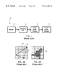
- an apparatus 10 for creating such an image includes a memory 12 for storing a boundary representation of a model or scene, a rendering unit 14 , an image buffer 16 , and a frame buffer 18 .
- the rendering unit 14 includes one or more processors capable of determining the addresses and color values of all pixels associated with each component of the scene or model.
- the image buffer 16 is a memory with a capacity of at least m ⁇ n ⁇ p bytes, where m is a number of rows in the generated image, n is the number of columns, and p is the number of bytes required to represent each pixel.
- the frame buffer 18 may be a special memory associated with video digital-to-analog converters (DACs) which produce a visible representation of the image on a cathode ray tube (CRT).
- DACs video digital-to-analog converters
- CRT cathode ray tube
- the frame buffer 18 may be a data file or other data structure.
- the image buffer 16 and frame buffer 18 may be the same physical memory.
- a primitive such as a triangle 20
- the process of rasterizing a drawing primitive associates pixels with the primitive on an all or nothing basis. For example, if the center of a particular pixel lies within the area of a particular drawing primitive, then the color of that pixel is determined exclusively by that primitive, and other drawing primitives, which may also partially cover the same pixel, are ignored.
- the result of associating pixels with drawing primitives on an all or nothing basis results in jagged lines along the boundary of a primitive, as shown in FIG. 2 B. These jagged boundaries in an image are an undesirable artifact known as aliasing. Techniques for avoiding these artifacts are known as anti-aliasing techniques.
- the problem of aliasing may be diminished by super-sampling in which the color of a pixel is determined by a number of points within the area of the pixel instead of representing the pixel by its center.
- an image i ⁇ m rows and j ⁇ n columns is generated, where i and j are the super-sampling factors.
- each i ⁇ j block of pixels in the super-image is averaged to determine one pixel in the final m ⁇ n anti-aliased image.
- the color of each pixel in the resulting image reflects the portions of the pixel covered by each drawing primitive, as shown in FIG. 3 C.
- an apparatus 40 required to create an anti-aliased image with the super-image method is shown.
- this apparatus has a super-image buffer 42 and an image reduction unit 44 .
- the image reduction unit 44 determines one pixel in the image buffer 16 based on the average value for each i ⁇ j block of pixels in the super-image buffer 42 .
- the principal problem with the super-image technique is the massive amount of memory required to hold the super-image.
- a conventional image with a resolution of 600 rows, 800 columns, and 3 bytes per pixel requires nearly 1.5 Mbytes.
- an alternative apparatus 50 for generating an anti-aliased image is the use of an accumulation buffer 52 .
- a conventional m ⁇ n image buffer with e.g., 8-bits for each color value is supplemented with a second mxn buffer having 16-bits for each color buffer.
- the accumulation buffer 52 is initially cleared to all zeroes. Then the entire scene is rendered into the first buffer i ⁇ j times, shifting the entire image by multiples of (1/i) rows and (1/j) columns each time. In effect, each rendering pass determines the pixel values determined by every ith row and every jth column of the super-image.
- each color value in the accumulation buffer 52 is divided (block 58 ) by i ⁇ j, truncated to an 8-bit integer, and copied back to the image buffer 16 .
- This allows an image to be sampled with up to 256 samples per pixel using only a fixed modest amount of memory beyond that required by the original image buffer 16 .
- One drawback of this is that the entire image must be rendered many times resulting in a severe performance penalty.
- the “accumulation buffer” method may be summarized as follows:
- step b1. Create a digital model of the object(s) or scenery to be rendered.
- step b2 Decide on the resolution of the image to be generated by the rendering process (for example, this may be 640 ⁇ 480, 1280 ⁇ 1024, etc.).
- step b3. Traverse the digital model many times. Clipping boundaries are shifted by a fraction of a pixel on each traversal, and each traversal produces a complete image at the full resolution. For example, the model may be traversed 16 times corresponding to shifting the horizontal and vertical clipping boundaries by ( ⁇ 3 ⁇ 8, ⁇ 1 ⁇ 8, +1 ⁇ 8, and +3 ⁇ 8) pixel.
- step b4 On each traversal, each element of the model is processed. That is, the geometry processing is performed and then the results of the geometry processing are immediately passed on to the rasterization processing. This is fully compatible with standard hardware accelerators for 3d graphics.
- step b5 The image created in step b4 is added into a special buffer called an “accumulation buffer”.
- An accumulation buffer is similar to an ordinary image buffer, except that the accumulation buffer has 16 bits for each component (r, g, b, and possibly alpha) of each pixel. Each of these components is also called a “sample”.
- the accumulation buffer is not compatible with standard image buffers because it requires 16-bits per sample
- step b6 After completing the final traversal, the final image is calculated by dividing each 16-bit component of the accumulation buffer by the number of traversals. The results are stored in a standard image buffer.
- PixarTM Corp. Another technique has been implemented by PixarTM Corp. and forms a major part of their Photorealistic Renderman product.
- the PixarTM algorithm divides the work of the rendering unit into two stages, a transformation and clipping stage, and a rasterization stage. The output image is divided into many small blocks.
- the scene or model is passed to the first stage of the rendering unit only once.
- Each drawing primitive is transformed and assigned to one or more buckets based on the screen blocks touched by the primitive.
- the second stage of the rendering unit is used to process each of the buckets created by the first stage.
- the contents of each bucket are processed with a super-image technique applied to a small part of the complete image.
- the resulting super-image is reduced to a small image which forms one block in the final anti-aliased image.
- PixarTM One drawback to the PixarTM algorithm is the need to store a copy of the scene or model between the two stages of the rendering process. The amount of storage needed for this copy of the model cannot be bounded and can be very large for complex models.
- PixarTM uses a rendering algorithm that they call “REYES” (Render Everything You Ever Saw). This is incorporated in their product called “PhotoRealistic RenderMan”. This algorithm is summarized below. Before the PixarTM algorithm is examined, first consider the “standard” 3d rendering algorithm for reference.
- the “standard” 3d rendering algorithm may be summarized as:
- step s1. Create a digital model of the object(s) or scenery to be rendered. This is a collection of geometrical primitives, material properties, light sources, transformation matrices, etc. which define the properties of the object(s) or scenery.
- step s2 Decide on the resolution of the image to be generated by the rendering process (for example, this may be 640 ⁇ 480, 1280 ⁇ 1024, etc.).
- the digital model is “traversed”, meaning that each element is selected and processed in sequence.
- step s4 The processing of each geometric element consists of two stages: “geometric processing”, and rasterization”. Both stages are performed in turn for each element of the digital model. That is, for each element, the geometric processing is performed. The results of the geometric processing of this element are then immediately used as input for the rasterization process for the same element. The results of the rasterization process are used to update the image defined in step s2. The results of the geometric processing are discarded after being used as input to the rasterization process.
- the “geometric” processing includes transformations, lighting, perspective projection, and clipping the results to the “viewing frustum” defined by the view direction and field of view chosen for this image.
- the “rasterization” processing includes identifying a set of individual pixels associated with a given geometric element in the target image, along with a color value and possibly a transparency value for each of these pixels.
- One advantage of the standard algorithm is that it is not necessary to save the intermediate results determined by the geometry processing. These values are fed directly to the rasterization step and then discarded.
- the PixarTM algorithm may be summarized as:
- step p1 Create a digital model of the object(s) or scenery to be rendered. This is the same as in step s1.
- step p2 Decide on the resolution of the image to be generated by the rendering process (for example, this may be 640 ⁇ 480, 1280 ⁇ 1024, etc.). Same as step s2.
- step p3 Divide the image defined in step p2 into a large number of small squares. These are typically assigned a size of 32 ⁇ 32, but these could be larger or smaller. A data structure called a “bucket” is created for each of the blocks comprising the complete image. (This is a new step not found in the standard algorithm)
- step p4 The digital model is “traversed”, meaning that each element is selected and processed in sequence. This is equivalent to step s3.
- step p5. Perform the geometry processing for each element of the digital model encountered in step p4. The results of this process are used to determine which bucket(s) is/are affected by each element of the digital model. Each affected bucket is updated to reflect the results of the geometry processing.
- the geometry processing performed in this step is equivalent to the geometry processing performed in step s4 of the standard algorithm. No rasterization processing is performed in step p5. Each element is expected to affect only a few buckets.
- step p6 After completing the traversal of the digital model, each of the buckets is examined to determine which elements of the digital model affect each block of image pixels. In most cases, only a few elements of the complete model are expected to be associated with each bucket. These may be sorted by depth and rasterized to determine the colors of each pixel in the small block of pixels associated with each bucket.
- Each block processed in step p6 block may optionally (and typically) be rasterized at a resolution greater than the size of the block defined in step p3. For example, if each block has the size of 32 ⁇ 32, then it may be rasterized at a resolution such as 128 ⁇ 128. The resulting 128 ⁇ 128 image is then reduced to 32 ⁇ 32 by averaging blocks of pixels within the 128 ⁇ 128 image. This produces an anti-aliased image.
- step p8 The results of rasterizing each bucket (i.e., a block of pixels) are copied into the corresponding portion of the final image.
- the final image is completed when the last bucket is processed.
- this algorithm requires saving all of the intermediate results of the geometry processing. These results are stored in the array of buckets defined in step p3. This array of buckets may require a large amount of space. This storage requirement is a significant disadvantage. On the other hand, each of the buckets may be processed independently, making this very amenable to parallel processing.
- PixarTM algorithm is incompatible with typical hardware accelerators for 3d graphics because devices do not allow the results of the geometry processing to be captured and saved into any kind of persistent data storage. These devices assume and require the results of the geometry processing to be passed immediately and directly to the rasterization stage as seen in the standard algorithm.
- a program storage device readable by-machine, tangibly embodying a program of instructions executable by the machine to perform method steps for creating anti-aliased images and/or a method for creating anti-aliased images includes the steps of providing a subject to be rendered, defining an output resolution of a complete image to be generated by rendering the subject, dividing the complete image into a number of image portions, the number of image portions being determined by an anti-aliasing quality, each image portion having a number of pixels determined by the output resolution of the complete image and the number of image portions, processing the complete image by traversing the subject multiple times to create an intermediate image for each image portion, the intermediate image having a greater number of pixels than the image portion, determining each pixel within the image portion by averaging over blocks of pixels in the intermediate image and combining the image portions to generate the complete anti-aliased image with the output resolution.
- the step of processing may include the steps of performing geometric processing and immediately passing results of the geometric processing to rasterization processing.
- the step of processing may include the step of adjusting clipping boundaries on each traversal to select blocks of pixels to be processed.
- the step of processing the image by traversing may include the step of traversing the subject a number of times equal to a predetermined sub-sampling for each pixel determined by the anti-aliasing quality.
- the subject may include a digital model of one of objects and scenery to be rendered.
- the step of reproducing the image portions to produce a final anti-aliased image may include the step of generating an anti-aliased image with resolution of m rows and n columns based on rendering the subject to be rendered i ⁇ j successive times in which each successive rendering is defined by a contiguous m ⁇ n block within the image having i ⁇ m rows and j ⁇ n columns.
- a system for creating anti-aliased images includes a memory storage device for storing a boundary representation of an image.
- a rendering unit is coupled to the memory storage device for determining addresses and color values of all pixels associated the image.
- a first image buffer is coupled to the rendering unit to receive results from a multiplicity of rendering passes for blocks of i ⁇ j pixels, the first image buffer including a memory with a capacity of at least m ⁇ n ⁇ p bytes, where m is a number of rows in the image, n is the number of columns in the image, and p is the number of bytes needed to represent each pixel.
- An image reduction unit is coupled to the first image buffer for determining one pixel in the first image buffer based on an average value for each i ⁇ j block of pixels in the first image buffer.
- a second image buffer is coupled to the image reduction unit having a same size memory capacity as the first image buffer, the second image buffer providing an anti-aliased image after completing the multiplicity of rendering passes.
- the memory capacity of the second image buffer is preferably sufficient to produce the anti-aliased image with a same resolution as the image in the second image buffer.
- the system may further include a frame buffer for producing a visible representation of the anti-aliased image.
- the frame buffer may include a memory associated with video digital-to-analog converters which produce the visible representation of the image on a display.
- the frame buffer may have a memory capacity equal to the memory capacity of the second image buffer.
- the first image buffer may be employed as a frame buffer for producing a visible representation of the anti-aliased image.
- FIG. 1 is a block diagram of an apparatus for creating a computer generated image in accordance with the prior art
- FIG. 2A depicts an outline of a triangle over squares representing pixels
- FIG. 2B depicts a representation of the triangle of FIG. 2A with a set of pixels in accordance with the prior art
- FIG. 3A depicts an outline of a triangle over squares representing higher resolution pixels
- FIG. 3B depicts a representation of the triangle of FIG. 3A with a set of pixels in accordance with the prior art
- FIG. 3C depicts a representation of the triangle of FIG. 3B with a set of pixels having different shading to represent locations of the pixels being inside, outside or on the boundary of the triangle in accordance with the prior art;
- FIG. 4 is a block diagram of an apparatus for superimage anti-aliasing in accordance with the prior art
- FIG. 5 is a block diagram of an apparatus for creating an image with an accumulation buffer in accordance with the prior art
- FIG. 6 is a block diagram of an apparatus for creating an anti-aliased image in accordance with the present invention.
- FIG. 7 is a flow diagram showing a method for creating an anti-aliased image in accordance with the present invention.
- the present invention relates to the creation and rendering of electronic images, and more particularly to anti-aliased electronic images provided by a memory efficient system and method.
- the present invention provides an alternative to the super-image technique and the accumulation buffer technique as described above. Instead of an accumulation buffer with 16 bits per color value, the present invention provides a second image buffer with only 8 bits for each color value. In alternate embodiments, a frame buffer for the present invention may be used as the second image buffer.
- System 100 includes a memory 102 for storing a boundary representation of a subject which may include a model or scene or other representations, a rendering unit 104 , an image buffer 106 , and a frame buffer 108 .
- the rendering unit 104 includes one or more processors capable of determining the addresses and color values of all pixels associated with each component of the scene or model.
- the image buffer 106 is a memory with a capacity of at least m ⁇ n ⁇ p bytes, where m is a number of rows in the generated image, n is the number of columns, and p is the number of bytes needed to represent each pixel.
- the frame buffer 108 may be a special memory associated with video digital-to-analog converters (DACs) which produce a visible representation of the image on, for example, a cathode ray tube (CRT) or other display.
- the frame buffer 108 may be a data file or other data structure with a capacity of at least m ⁇ n ⁇ p bytes. In other embodiments, the image buffer 106 and frame buffer 108 may be the same physical memory.
- a second image buffer 110 is included which has the same size as the image buffer 106 . That is, if the image buffer 106 is based on 8 bits for each color value, then the second buffer 110 needs only 8 bits for each value, not 16 bits as required by the accumulation buffer of the prior art.
- the present invention provides a model or scene to be rendered i ⁇ j times. Instead of rendering every ith row and jth column of the super-image, an m ⁇ n block of contiguous pixels within the super-image is determined on each rendering pass.
- each i ⁇ j sub-block of pixels within the resulting n ⁇ m image is averaged to determine one pixel within an (m/i) ⁇ (n/j) block in the second buffer 110 .
- the image reduction unit 112 is coupled to an output of image buffer 106 and outputs the reduced image to the second buffer 110 .
- the image reduction unit 112 determines one pixel in the image buffer 106 based on the average value for each i ⁇ j block of pixels in the image buffer 106 .
- the results of two or more passes are combined to determine the values for the pixels on the boundaries of the (m/i) ⁇ (n/j) blocks of the second image buffer 110 .
- the second buffer 110 includes a complete anti-aliased image of the model or scene.
- the contents of the second buffer 110 may then be copied to the frame buffer 108 with no further processing. In other embodiments, it is also possible to skip the second buffer 110 entirely and update the frame buffer 108 immediately with the results of each rendering pass.
- each of the i ⁇ j rendering passes is based on only a small portion of the aliased image. Most of the elements of the model or scene which are included in the aliased image will be outside the portion of the image rendered on any single rendering pass. That is, most elements of a scene or model will be rejected on each pass. Since rejected elements need much less effort than elements which are not rejected, each rendering pass provided by this invention will take much less time than that needed for the aliased image.
- the conventional accumulation buffer technique requires 3M bytes of memory and i ⁇ j ⁇ T seconds to determine an anti-aliased image equivalent to an i ⁇ m by j ⁇ n super-image.
- the present invention needs only 2M bytes of memory with the second image buffer 110 , or only M bytes if the second image buffer 110 is not used.
- the time needed by the present invention may be estimated as (T+i ⁇ j ⁇ R) where R is the time required to reject the entire scene. Since R is generally much less than T, the time needed by this invention will be much less than that required by the conventional accumulation buffer method.
- the rendering unit 104 there is no need for the rendering unit 104 to store a copy of the scene of model, as with the PixarTM method described above.
- a subject which may include a digital model of an object(s) or scenery to be rendered is created. This is a collection of geometrical primitives, material properties, light sources, transformation matrices, etc. which define the properties of the object(s) or scenery.
- an output resolution of the image to be generated by the rendering process of the subject is decided (for example, this may be 640 ⁇ 480, 1280 ⁇ 1024, etc.).
- the image defined in block 204 is divided into a small number of large blocks. For example, a 1280 ⁇ 1024 image may be divided into 4 blocks of 640 ⁇ 512 or 16 blocks of 320 ⁇ 256.
- step 208 the subject is traversed for each block defined in block 206 .
- the traversal is now performed multiple times in accordance with the present invention whereas the traversal is performed only once in the prior art.
- clipping boundaries are adjusted to select the corresponding block of the image defined in block 204 .
- each element of the subject is processed. That is, the geometry processing is performed and then the results of the geometry processing are immediately passed on to the rasterization processing.
- the number of traversals is determined by the quality of the anti-aliasing. To obtain 4 ⁇ 4 sub-sampling of each pixel, for example, it would be necessary to traverse the model 16 times.
- this is fully compatible with standard hardware accelerators for 3d graphics.
- the image created has the full (or intermediate) resolution of the image defined in block 204 , not the smaller size defined in block 206 , but the clipping boundaries are set as specified in block 208 .
- the image created in block 210 is used to create a smaller image by averaging blocks of pixels from the larger image. For example, if a 1280 ⁇ 1024 image has been divided into 16 blocks of size 320 ⁇ 256, then the image produced in block 210 has a resolution of 1280 ⁇ 1024 which is reduced to 320 ⁇ 256 by averaging the contents of 4 ⁇ 4 blocks of pixels in the larger (1280 ⁇ 1024) image to determine one pixel in the smaller (320 ⁇ 256) image.
- the small images obtained in block 212 are each copied into the corresponding portion of the final full-sized image. The final anti-aliased image is completed after the final traversal of the model and copy of the last block of pixels into the final image.
- the present invention provides many traversals. Further, results of geometry processing for each element are immediately sent to be rasterized, nothing is saved. This reduces the need for a large amount of memory and more efficiently uses the available memory. According to the invention, each element is rasterized immediately after geometry processing for that element.
- the present invention is 3d hardware compatible because rasterization immediately follows geometry processing (i.e.,no deferred rasterization).
Abstract
Description
Claims (23)
Priority Applications (1)
| Application Number | Priority Date | Filing Date | Title |
|---|---|---|---|
| US09/282,813 US6421060B1 (en) | 1999-03-31 | 1999-03-31 | Memory efficient system and method for creating anti-aliased images |
Applications Claiming Priority (1)
| Application Number | Priority Date | Filing Date | Title |
|---|---|---|---|
| US09/282,813 US6421060B1 (en) | 1999-03-31 | 1999-03-31 | Memory efficient system and method for creating anti-aliased images |
Publications (1)
| Publication Number | Publication Date |
|---|---|
| US6421060B1 true US6421060B1 (en) | 2002-07-16 |
Family
ID=23083230
Family Applications (1)
| Application Number | Title | Priority Date | Filing Date |
|---|---|---|---|
| US09/282,813 Expired - Lifetime US6421060B1 (en) | 1999-03-31 | 1999-03-31 | Memory efficient system and method for creating anti-aliased images |
Country Status (1)
| Country | Link |
|---|---|
| US (1) | US6421060B1 (en) |
Cited By (12)
| Publication number | Priority date | Publication date | Assignee | Title |
|---|---|---|---|---|
| US6567098B1 (en) * | 2000-06-22 | 2003-05-20 | International Business Machines Corporation | Method and apparatus in a data processing system for full scene anti-aliasing |
| US20030218694A1 (en) * | 2002-05-23 | 2003-11-27 | Yu-Rong Wang | Anti-aliasing characters for improved display on an interlaced television monitor |
| US20050235287A1 (en) * | 2004-04-16 | 2005-10-20 | John Harper | System for emulating graphics operations |
| US20050231516A1 (en) * | 2004-04-16 | 2005-10-20 | Apple Computer, Inc. | System and method for processing graphics operations with graphics processing unit |
| US20050231514A1 (en) * | 2004-04-16 | 2005-10-20 | John Harper | System for optimizing graphics operations |
| US20050285866A1 (en) * | 2004-06-25 | 2005-12-29 | Apple Computer, Inc. | Display-wide visual effects for a windowing system using a programmable graphics processing unit |
| US20060125839A1 (en) * | 2004-04-16 | 2006-06-15 | John Harper | System for reducing the number of programs necessary to render an image |
| US20060250414A1 (en) * | 2005-05-03 | 2006-11-09 | Vladimir Golovin | System and method of anti-aliasing computer images |
| US20070182747A1 (en) * | 2004-04-16 | 2007-08-09 | John Harper | High-level program interface for graphics operations |
| US20070182749A1 (en) * | 2004-06-25 | 2007-08-09 | Apple Computer, Inc. | Partial display updates in a windowing system using a programmable graphics processing unit |
| US7266250B2 (en) | 2000-01-19 | 2007-09-04 | Xerox Corporation | Methods for generating anti-aliased text and line graphics in compressed document images |
| US20140105521A1 (en) * | 2002-02-13 | 2014-04-17 | Canon Kabushiki Kaisha | Data processing apparatus, image processing apparatus, and method therefor |
Citations (8)
| Publication number | Priority date | Publication date | Assignee | Title |
|---|---|---|---|---|
| US5600773A (en) * | 1991-07-23 | 1997-02-04 | International Business Machines Corporation | Logical partitioning of gamma ramp frame buffer for overlay or animation |
| US5748946A (en) | 1995-02-17 | 1998-05-05 | International Business Machines Corporation | Method and apparatus for improved graphics picking using auxiliary buffer information |
| US5864342A (en) * | 1995-08-04 | 1999-01-26 | Microsoft Corporation | Method and system for rendering graphical objects to image chunks |
| US5940080A (en) * | 1996-09-12 | 1999-08-17 | Macromedia, Inc. | Method and apparatus for displaying anti-aliased text |
| US5977977A (en) * | 1995-08-04 | 1999-11-02 | Microsoft Corporation | Method and system for multi-pass rendering |
| US6083162A (en) * | 1994-10-27 | 2000-07-04 | Wake Forest University | Method and system for producing interactive, three-dimensional renderings of selected body organs having hollow lumens to enable simulated movement through the lumen |
| US6115050A (en) * | 1998-04-08 | 2000-09-05 | Webtv Networks, Inc. | Object-based anti-aliasing |
| US6151030A (en) * | 1998-05-27 | 2000-11-21 | Intel Corporation | Method of creating transparent graphics |
-
1999
- 1999-03-31 US US09/282,813 patent/US6421060B1/en not_active Expired - Lifetime
Patent Citations (8)
| Publication number | Priority date | Publication date | Assignee | Title |
|---|---|---|---|---|
| US5600773A (en) * | 1991-07-23 | 1997-02-04 | International Business Machines Corporation | Logical partitioning of gamma ramp frame buffer for overlay or animation |
| US6083162A (en) * | 1994-10-27 | 2000-07-04 | Wake Forest University | Method and system for producing interactive, three-dimensional renderings of selected body organs having hollow lumens to enable simulated movement through the lumen |
| US5748946A (en) | 1995-02-17 | 1998-05-05 | International Business Machines Corporation | Method and apparatus for improved graphics picking using auxiliary buffer information |
| US5864342A (en) * | 1995-08-04 | 1999-01-26 | Microsoft Corporation | Method and system for rendering graphical objects to image chunks |
| US5977977A (en) * | 1995-08-04 | 1999-11-02 | Microsoft Corporation | Method and system for multi-pass rendering |
| US5940080A (en) * | 1996-09-12 | 1999-08-17 | Macromedia, Inc. | Method and apparatus for displaying anti-aliased text |
| US6115050A (en) * | 1998-04-08 | 2000-09-05 | Webtv Networks, Inc. | Object-based anti-aliasing |
| US6151030A (en) * | 1998-05-27 | 2000-11-21 | Intel Corporation | Method of creating transparent graphics |
Cited By (45)
| Publication number | Priority date | Publication date | Assignee | Title |
|---|---|---|---|---|
| US7266250B2 (en) | 2000-01-19 | 2007-09-04 | Xerox Corporation | Methods for generating anti-aliased text and line graphics in compressed document images |
| US7489830B2 (en) | 2000-01-19 | 2009-02-10 | Xerox Corporation | Methods for generating anti-aliased text and line graphics in compressed document images |
| US20080024843A1 (en) * | 2000-01-19 | 2008-01-31 | Xerox Corporation | Methods for generating anti-aliased text and line graphics in compressed document images |
| US6567098B1 (en) * | 2000-06-22 | 2003-05-20 | International Business Machines Corporation | Method and apparatus in a data processing system for full scene anti-aliasing |
| US9361664B2 (en) * | 2002-02-13 | 2016-06-07 | Canon Kabushiki Kaisha | Data processing apparatus, image processing apparatus, and method therefor |
| US20140105521A1 (en) * | 2002-02-13 | 2014-04-17 | Canon Kabushiki Kaisha | Data processing apparatus, image processing apparatus, and method therefor |
| US20030218694A1 (en) * | 2002-05-23 | 2003-11-27 | Yu-Rong Wang | Anti-aliasing characters for improved display on an interlaced television monitor |
| US6995803B2 (en) * | 2002-05-23 | 2006-02-07 | Microsoft Corporation | Anti-aliasing characters for improved display on an interlaced television monitor |
| US20060092176A1 (en) * | 2002-05-23 | 2006-05-04 | Microsoft Corporation | Anti-aliasing characters for improved display on an interlaced television monitor |
| US7440037B2 (en) | 2002-05-23 | 2008-10-21 | Microsoft Corporation | Anti-aliasing characters for improved display on an interlaced television monitor |
| US7788656B2 (en) | 2004-04-16 | 2010-08-31 | Apple Inc. | System for reducing the number of programs necessary to render an image |
| US8044963B2 (en) | 2004-04-16 | 2011-10-25 | Apple Inc. | System for emulating graphics operations |
| US20070182747A1 (en) * | 2004-04-16 | 2007-08-09 | John Harper | High-level program interface for graphics operations |
| US10402934B2 (en) | 2004-04-16 | 2019-09-03 | Apple Inc. | System for optimizing graphics operations |
| US9691118B2 (en) | 2004-04-16 | 2017-06-27 | Apple Inc. | System for optimizing graphics operations |
| US20070247468A1 (en) * | 2004-04-16 | 2007-10-25 | Mark Zimmer | System and method for processing graphics operations with graphics processing unit |
| US20050235287A1 (en) * | 2004-04-16 | 2005-10-20 | John Harper | System for emulating graphics operations |
| US20060125838A1 (en) * | 2004-04-16 | 2006-06-15 | John Harper | System for reducing the number of programs necessary to render an image |
| US20060125839A1 (en) * | 2004-04-16 | 2006-06-15 | John Harper | System for reducing the number of programs necessary to render an image |
| US8704837B2 (en) | 2004-04-16 | 2014-04-22 | Apple Inc. | High-level program interface for graphics operations |
| US7667709B2 (en) | 2004-04-16 | 2010-02-23 | Apple Inc. | System and method for processing graphics operations with graphics processing unit |
| US20100214305A1 (en) * | 2004-04-16 | 2010-08-26 | Apple Inc. | System and Method for Processing Graphics Operations with Graphics Processing Unit |
| US20050231514A1 (en) * | 2004-04-16 | 2005-10-20 | John Harper | System for optimizing graphics operations |
| US7847800B2 (en) | 2004-04-16 | 2010-12-07 | Apple Inc. | System for emulating graphics operations |
| US20110037768A1 (en) * | 2004-04-16 | 2011-02-17 | Apple Inc. | System for Emulating Graphics Operations |
| US7911472B2 (en) | 2004-04-16 | 2011-03-22 | Apple Inc. | System for reducing the number of programs necessary to render an image |
| US20110074821A1 (en) * | 2004-04-16 | 2011-03-31 | Apple Inc. | System for Emulating Graphics Operations |
| US20110074810A1 (en) * | 2004-04-16 | 2011-03-31 | Apple Inc. | System for Emulating Graphics Operations |
| US20050231516A1 (en) * | 2004-04-16 | 2005-10-20 | Apple Computer, Inc. | System and method for processing graphics operations with graphics processing unit |
| US20110169857A1 (en) * | 2004-04-16 | 2011-07-14 | Apple Inc. | System for Optimizing Graphics Operations |
| US20110187736A1 (en) * | 2004-04-16 | 2011-08-04 | Apple Inc. | System and Method for Processing Graphics Operations with Graphics Processing Unit |
| US8009176B2 (en) | 2004-04-16 | 2011-08-30 | Apple Inc. | System and method for processing graphics operations with graphics processing unit |
| US8520021B2 (en) | 2004-04-16 | 2013-08-27 | Apple Inc. | System and method for processing graphics operations with graphics processing unit |
| US8040359B2 (en) | 2004-04-16 | 2011-10-18 | Apple Inc. | System for emulating graphics operations |
| US8040353B2 (en) | 2004-04-16 | 2011-10-18 | Apple Inc. | System for emulating graphics operations |
| US7248265B2 (en) * | 2004-04-16 | 2007-07-24 | Apple Inc. | System and method for processing graphics operations with graphics processing unit |
| US8134561B2 (en) | 2004-04-16 | 2012-03-13 | Apple Inc. | System for optimizing graphics operations |
| US8446416B2 (en) | 2004-04-16 | 2013-05-21 | Apple Inc. | System for optimizing graphics operations |
| US8144159B2 (en) | 2004-06-25 | 2012-03-27 | Apple Inc. | Partial display updates in a windowing system using a programmable graphics processing unit |
| US20110216079A1 (en) * | 2004-06-25 | 2011-09-08 | Apple Inc. | Partial Display Updates in a Windowing System Using a Programmable Graphics Processing Unit |
| US7969453B2 (en) | 2004-06-25 | 2011-06-28 | Apple Inc. | Partial display updates in a windowing system using a programmable graphics processing unit |
| US20050285866A1 (en) * | 2004-06-25 | 2005-12-29 | Apple Computer, Inc. | Display-wide visual effects for a windowing system using a programmable graphics processing unit |
| US20070257925A1 (en) * | 2004-06-25 | 2007-11-08 | Apple Computer, Inc. | Partial display updates in a windowing system using a programmable graphics processing unit |
| US20070182749A1 (en) * | 2004-06-25 | 2007-08-09 | Apple Computer, Inc. | Partial display updates in a windowing system using a programmable graphics processing unit |
| US20060250414A1 (en) * | 2005-05-03 | 2006-11-09 | Vladimir Golovin | System and method of anti-aliasing computer images |
Similar Documents
| Publication | Publication Date | Title |
|---|---|---|
| JP4540753B2 (en) | Method and system for rendering graphic objects into image chunks and combining image layers with a display image | |
| EP0934574B1 (en) | Method and apparatus for attribute interpolation in 3d graphics | |
| US6115049A (en) | Method and apparatus for high performance antialiasing which minimizes per pixel storage and object data bandwidth | |
| US6825847B1 (en) | System and method for real-time compression of pixel colors | |
| US5613050A (en) | Method and apparatus for reducing illumination calculations through efficient visibility determination | |
| US6038031A (en) | 3D graphics object copying with reduced edge artifacts | |
| US20210097642A1 (en) | Graphics processing | |
| JP3761085B2 (en) | Image processing apparatus, components thereof, and rendering processing method | |
| US11393165B2 (en) | Method and system for multisample antialiasing | |
| EP3563349A1 (en) | Variable rate shading | |
| US6577307B1 (en) | Anti-aliasing for three-dimensional image without sorting polygons in depth order | |
| US20160260249A1 (en) | Method and apparatus for processing computer graphics primitives in tile-based graphics rendering system | |
| US6421060B1 (en) | Memory efficient system and method for creating anti-aliased images | |
| US7711162B2 (en) | Accelerated texture-based fusion renderer | |
| JP2012014714A (en) | Method and device for rendering translucent 3d graphic | |
| US20020075285A1 (en) | Pixel zoom system and method for a computer graphics system | |
| US6906715B1 (en) | Shading and texturing 3-dimensional computer generated images | |
| US6741243B2 (en) | Method and system for reducing overflows in a computer graphics system | |
| JP5282092B2 (en) | Multi-sample rendering of 2D vector images | |
| US20070211078A1 (en) | Image Processing Device And Image Processing Method | |
| WO1998053425A1 (en) | Image processor and image processing method | |
| US6501481B1 (en) | Attribute interpolation in 3D graphics | |
| US6765588B2 (en) | Multisample dithering with shuffle tables | |
| US20090154834A1 (en) | Rendering system and data processing method for the same | |
| EP0855682B1 (en) | Scan line rendering of convolutions |
Legal Events
| Date | Code | Title | Description |
|---|---|---|---|
| AS | Assignment |
Owner name: INTERNATIONAL BUSINESS MACHINES CORPORATION, NEW Y Free format text: ASSIGNMENT OF ASSIGNORS INTEREST;ASSIGNOR:LUKEN, WILLIAM L.;REEL/FRAME:009878/0984 Effective date: 19990324 |
|
| STCF | Information on status: patent grant |
Free format text: PATENTED CASE |
|
| FPAY | Fee payment |
Year of fee payment: 4 |
|
| FPAY | Fee payment |
Year of fee payment: 8 |
|
| REMI | Maintenance fee reminder mailed | ||
| FPAY | Fee payment |
Year of fee payment: 12 |
|
| SULP | Surcharge for late payment |
Year of fee payment: 11 |
|
| AS | Assignment |
Owner name: LINKEDIN CORPORATION, CALIFORNIA Free format text: ASSIGNMENT OF ASSIGNORS INTEREST;ASSIGNOR:INTERNATIONAL BUSINESS MACHINES CORPORATION;REEL/FRAME:035201/0479 Effective date: 20140331 |