US6426833B1 - Optical amplifier configuration including shared pumps - Google Patents
Optical amplifier configuration including shared pumps Download PDFInfo
- Publication number
- US6426833B1 US6426833B1 US09/628,259 US62825900A US6426833B1 US 6426833 B1 US6426833 B1 US 6426833B1 US 62825900 A US62825900 A US 62825900A US 6426833 B1 US6426833 B1 US 6426833B1
- Authority
- US
- United States
- Prior art keywords
- pump
- pumps
- output
- optical
- segments
- Prior art date
- Legal status (The legal status is an assumption and is not a legal conclusion. Google has not performed a legal analysis and makes no representation as to the accuracy of the status listed.)
- Expired - Lifetime
Links
- 230000003287 optical effect Effects 0.000 title claims abstract description 52
- 239000013307 optical fiber Substances 0.000 claims description 8
- 229910052691 Erbium Inorganic materials 0.000 claims description 3
- 238000004891 communication Methods 0.000 claims description 3
- UYAHIZSMUZPPFV-UHFFFAOYSA-N erbium Chemical compound [Er] UYAHIZSMUZPPFV-UHFFFAOYSA-N 0.000 claims description 3
- 229910052761 rare earth metal Inorganic materials 0.000 claims description 3
- 229910052777 Praseodymium Inorganic materials 0.000 claims description 2
- 229910052769 Ytterbium Inorganic materials 0.000 claims description 2
- 239000000203 mixture Substances 0.000 claims description 2
- PUDIUYLPXJFUGB-UHFFFAOYSA-N praseodymium atom Chemical compound [Pr] PUDIUYLPXJFUGB-UHFFFAOYSA-N 0.000 claims description 2
- NAWDYIZEMPQZHO-UHFFFAOYSA-N ytterbium Chemical compound [Yb] NAWDYIZEMPQZHO-UHFFFAOYSA-N 0.000 claims description 2
- 229910052779 Neodymium Inorganic materials 0.000 claims 1
- QEFYFXOXNSNQGX-UHFFFAOYSA-N neodymium atom Chemical compound [Nd] QEFYFXOXNSNQGX-UHFFFAOYSA-N 0.000 claims 1
- 239000000835 fiber Substances 0.000 abstract description 82
- 238000005086 pumping Methods 0.000 description 7
- 238000010586 diagram Methods 0.000 description 4
- 230000008878 coupling Effects 0.000 description 3
- 238000010168 coupling process Methods 0.000 description 3
- 238000005859 coupling reaction Methods 0.000 description 3
- 239000002019 doping agent Substances 0.000 description 3
- 230000003321 amplification Effects 0.000 description 2
- 239000000463 material Substances 0.000 description 2
- 238000003199 nucleic acid amplification method Methods 0.000 description 2
- 238000001069 Raman spectroscopy Methods 0.000 description 1
- 230000005540 biological transmission Effects 0.000 description 1
- 238000006243 chemical reaction Methods 0.000 description 1
- 230000000694 effects Effects 0.000 description 1
- 238000000034 method Methods 0.000 description 1
- 230000000116 mitigating effect Effects 0.000 description 1
- -1 neodynium Chemical compound 0.000 description 1
- 230000000644 propagated effect Effects 0.000 description 1
- 150000002910 rare earth metals Chemical class 0.000 description 1
- 239000004065 semiconductor Substances 0.000 description 1
- 230000003595 spectral effect Effects 0.000 description 1
- 238000005728 strengthening Methods 0.000 description 1
Images


Classifications
-
- H—ELECTRICITY
- H01—ELECTRIC ELEMENTS
- H01S—DEVICES USING THE PROCESS OF LIGHT AMPLIFICATION BY STIMULATED EMISSION OF RADIATION [LASER] TO AMPLIFY OR GENERATE LIGHT; DEVICES USING STIMULATED EMISSION OF ELECTROMAGNETIC RADIATION IN WAVE RANGES OTHER THAN OPTICAL
- H01S3/00—Lasers, i.e. devices using stimulated emission of electromagnetic radiation in the infrared, visible or ultraviolet wave range
- H01S3/05—Construction or shape of optical resonators; Accommodation of active medium therein; Shape of active medium
- H01S3/06—Construction or shape of active medium
- H01S3/063—Waveguide lasers, i.e. whereby the dimensions of the waveguide are of the order of the light wavelength
- H01S3/067—Fibre lasers
- H01S3/06754—Fibre amplifiers
-
- H—ELECTRICITY
- H01—ELECTRIC ELEMENTS
- H01S—DEVICES USING THE PROCESS OF LIGHT AMPLIFICATION BY STIMULATED EMISSION OF RADIATION [LASER] TO AMPLIFY OR GENERATE LIGHT; DEVICES USING STIMULATED EMISSION OF ELECTROMAGNETIC RADIATION IN WAVE RANGES OTHER THAN OPTICAL
- H01S3/00—Lasers, i.e. devices using stimulated emission of electromagnetic radiation in the infrared, visible or ultraviolet wave range
- H01S3/09—Processes or apparatus for excitation, e.g. pumping
- H01S3/091—Processes or apparatus for excitation, e.g. pumping using optical pumping
- H01S3/094—Processes or apparatus for excitation, e.g. pumping using optical pumping by coherent light
- H01S3/094003—Processes or apparatus for excitation, e.g. pumping using optical pumping by coherent light the pumped medium being a fibre
- H01S3/094011—Processes or apparatus for excitation, e.g. pumping using optical pumping by coherent light the pumped medium being a fibre with bidirectional pumping, i.e. with injection of the pump light from both two ends of the fibre
-
- H—ELECTRICITY
- H01—ELECTRIC ELEMENTS
- H01S—DEVICES USING THE PROCESS OF LIGHT AMPLIFICATION BY STIMULATED EMISSION OF RADIATION [LASER] TO AMPLIFY OR GENERATE LIGHT; DEVICES USING STIMULATED EMISSION OF ELECTROMAGNETIC RADIATION IN WAVE RANGES OTHER THAN OPTICAL
- H01S3/00—Lasers, i.e. devices using stimulated emission of electromagnetic radiation in the infrared, visible or ultraviolet wave range
- H01S3/09—Processes or apparatus for excitation, e.g. pumping
- H01S3/091—Processes or apparatus for excitation, e.g. pumping using optical pumping
- H01S3/094—Processes or apparatus for excitation, e.g. pumping using optical pumping by coherent light
- H01S3/09408—Pump redundancy
Definitions
- the present invention relates in general to optical amplifiers, and in particular to an optical amplifier configuration including shared pumps for use in optical communication systems.
- Optical amplifiers have become an essential component in transmission systems and networks to compensate for system losses, particularly in wavelength division multiplexed (WDM) or dense wavelength division multiplexed (DWDM) communication systems, wherein a plurality of distinct optical wavelengths or channels are multiplexed and propagated over an optical medium to a plurality of receivers.
- WDM wavelength division multiplexed
- DWDM dense wavelength division multiplexed
- one of the most efficient and commonly used amplifier devices is the Erbium-doped fiber amplifier (EDFA), which has a gain bandwidth of about 35 nm in the 1.55 ⁇ m wavelength region.
- EDFAs do not require conversion of an optical signal into an electronic signal and back.
- An EDFA operates by passing an optical signal (e.g. a discrete wavelength) through an erbium-doped fiber segment, and “pumping” the segment with light from another laser, thereby strengthening the optical signal and returning it to its original levels without leaving the fiber optic cable for separate electronic processing.
- the segment of fiber may be a segment of doped optical fiber in which the dopant is selected from materials that can produce laser action in the fiber segment.
- materials can include rare earth dopants such as erbium, neodynium, praseodymium, ytterbium, or mixtures thereof.
- Pumping of a doped fiber segment at a specific pump wavelength causes population inversion among the electron energy levels of the dopant, producing optical amplification of the wavelength division multiplexed optical signals.
- the amplifier configuration depends on the spectral bandwidth of the signal to be amplified.
- C-band amplifiers for example, operate in the range of approximately 1527 nm to approximately 1565 nm
- L-band amplifiers operate in the range of approximately 1565 nm to approximately 1610 nm.
- An L-band fiber may be approximately five times as long as the C-band amplifier fiber, or may be doped with approximately 5 to 6 times the erbium provided in the C-band fiber.
- pumps operating at approximately 980 nm are efficient.
- pumps operating at approximately 1480 nm are more efficient, since the use of a 980 nm pump results in only about 37% to 40% inversion.
- Typical configurations of EDFAs include two-stage and three-stage amplifiers.
- a two-stage optical amplifier can include two segments of erbium-doped fiber spaced by a relatively short length of undoped fiber, and three pumps (e.g. laser diodes).
- the first doped fiber segment i.e., the first stage
- the second doped fiber segment i.e., the second stage
- a three-stage optical amplifier can include three doped fiber segments spaced by two relatively short lengths of undoped fiber, and four pumps.
- FIG. 1 shows a prior art three-stage optical amplifier configuration with four separate pumps for amplifying an input signal 109 .
- a wavelength of light or is provided or “pumped” in a forward direction by the first pump 101 and the second pump 102 , at amplifying fiber segments 117 and 118 , respectively.
- the third pump 103 pumps amplifying fiber segment 119 in a forward direction
- the fourth pump 104 pumps fiber segment 119 in a reverse direction, and an amplified output signal 109 a is provided.
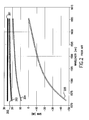
- FIG. 2 illustrates an exemplary gain vs. wavelength characteristic for the three-stage amplifier configuration of FIG. 1 in five different states.
- the first state as represented by curve 201
- all four pumps 101 - 104 are functioning normally.
- the second state as represented by curve 205
- the first pump 101 fails, i.e. suffers a reduction or complete loss of output power, or otherwise ceases to function properly.
- the third state as represented by curve 204
- the second pump 102 fails.
- the third pump 103 fails.
- the fourth pump 104 fails.
- a gain of about 26 dB may be obtained in the range of about 1572 to 1605 nm.
- the first pump 101 fails, a loss of approximately 45 dB is experienced.
- the second pump 102 fails, a gain of approximately 10-15 dB is experienced over the same range.
- the third pump 103 or the fourth pump 104 fails, a gain of about 21-24 dB is experienced.
- signals at shorter wavelengths are absorbed by the fiber to a far greater extent than signals at longer wavelengths.
- the third 103 or fourth pump 104 fails, failure of either of pumps 101 and 102 can result in a complete loss of the signal.
- the present invention is organized about the concept of pump sharing. Instead of each pump providing a wavelength of light directly into an amplifying fiber segment, the outputs of the pumps are combined and then divided before being injected into the fiber segments.
- a failsafe for preventing signal loss is provided, wherein power from at least one of the pumps is provided to each of the output fibers in the event a pump fails.
- an optical amplifier configuration consistent with the present invention includes: a plurality of optical pump sources, each pump source being configured to provide an output pump signal; a coupler configured to combine the pump signals into a combined signal; and a splitter for receiving the combined signal and splitting the combined signal into a plurality of separate signals, at least one of the separate signals being for introduction into at least one associated fiber segment for amplifying an optical signal.
- a three-stage optical amplifier configuration includes four pumps, three amplifying fiber segments, a coupler for combining a plurality of pump outputs, and a splitter for dividing the coupled output wavelength into separate output fibers, to be pumped into the fiber segments.
- the outputs from the first and second pumps are combined by the coupler, and the combined output is split by the splitter in half and provided in a forward direction into the first and second amplifying fiber segments.
- the third pump pumps the third amplifying fiber segment in a forward direction
- the fourth pump pumps the third amplifying fiber segment in a reverse direction.
- a two-stage optical amplifier configuration includes three pumps, two amplifying fiber segments, a coupler and a splitter.
- the output from the first pump is provided in a forward direction into the first amplifying fiber segment.
- the outputs from the second and third pumps are combined and split, and then provided in a forward and in a reverse direction into the second amplifying fiber segment.
- the output from the remaining pump is divided in half and is provided in a forward and a reverse direction into the second amplifying fiber segment, each of the output wavelengths being reduced to 50% of its original power.
- a method of pumping an amplifying optical fiber segment consistent with the invention includes the steps of: combining a plurality of optical pump signals into a combined pump signal; splitting the combined pump signal into separate pump signals; and introducing at least one of the separate pump signals into the fiber segment.
- FIG. 1 is a schematic diagram of a prior art three-stage optical amplifier configuration
- FIG. 2 illustrates gain vs. wavelength for the prior art three-stage optical amplifier configuration of FIG. 1 in five different states
- FIG. 3 is a schematic diagram of an exemplary embodiment of a three-stage optical amplifier configuration consistent with the present invention
- FIG. 4 illustrates gain v. wavelength for the exemplary three-stage optical amplifier configuration of FIG. 3, in two different states;
- FIG. 5 is a schematic diagram of an exemplary embodiment of a two-stage optical amplifier configuration consistent with the present invention
- FIG. 6 is a schematic diagram of an exemplary embodiment of a three-stage optical amplifier configuration consistent with the present invention.
- FIG. 7 illustrates gain v. wavelength for the exemplary three-stage optical amplifier configuration of FIG. 7, in two different states.
- FIG. 3 illustrates an exemplary embodiment of a three-stage optical amplifier configuration consistent with the present invention.
- the exemplary configuration includes three amplifying fiber segments 317 , 318 and 319 , four pumps 301 , 302 , 303 and 304 , a coupler 305 for combining the outputs of pumps 301 and 302 , and a splitter 306 for dividing the coupled output and providing the divided output to two separate output fibers 307 and 308 .
- the coupler 305 and splitter 306 are illustrated as separate elements. It is to be understood, however, that the coupler may be an optical device that can receive a plurality of optical inputs and combine them into one output on a single output path.
- the splitter may be any optical device that can divide an input optical wavelength and place it onto a plurality of output paths.
- one or more hybrid optical coupling devices may be used in place of the coupler, the splitter, or both.
- Such a hybrid device would receive a plurality of input optical wavelengths and provide a plurality of output optical wavelengths (e.g.
- an amplifying fiber segment, or waveguide, as defined herein includes any segment of fiber into which at least one pump wavelength is introduced for purposes of amplification (e.g. a fiber segment in a Raman fiber amplifier), and is not limited to rare earth-doped segments of fiber.
- pumps 301 and 302 provide outputs received by the coupler 305 .
- the coupler provides a combined output including the outputs of pumps 301 and 302 , to the splitter 306 .
- the splitter 306 divides the combined output into equal portions on two separate output fibers 307 and 308 .
- the output fibers 307 and 308 provide the output wavelengths into amplifying fiber segments 317 and 318 , respectively.
- Pump 303 directly pumps amplifying fiber segment 319 in a forward direction
- pump 304 directly pumps amplifying fiber segment 319 in a reverse direction.
- the input signal 309 is amplified by pumping the fiber segments 317 and 318 in a forward direction by the combined and re-divided outputs of the first pump 301 and the second pump 302 .
- the input signal is amplified by the third pump 303 , which directly pumps the segment 319 in a forward direction, and the fourth pump 304 , which directly pumps the segment 319 in a reverse direction.
- Amplified output signal 309 a is provided.
- failure of either the first 301 or second pump 302 results in the output from the remaining operating pump being divided in half and being provided in a forward direction, via output fibers 307 and 308 into fiber segments 317 and 318 , respectively.
- each of the output wavelengths is reduced to 50% of its original power.
- FIG. 4 illustrates gain vs. wavelength for the three-stage optical amplifier configuration of FIG. 3, in two different states.
- first state as represented by curve 401
- all four pumps 301 - 304 are functioning normally.
- second state as represented by curve 402
- either the first 301 or second pump 302 fails, and, due to the shared pump configuration consistent with the present invention, the shared output of the remaining operating pump is provided via output fibers 307 and 308 into fiber segments 317 and 318 , respectively.
- the normalized power of the four pumps may be at a ratio of 0.5:0.5:1:1, and a gain difference of less than 1 dB relative to the total gain is experienced in the range of approximately 1572 to 1605 nm.
- FIG. 4 particularly as compared to the prior art configuration illustrated by FIGS. 1 and 2, a shared pump configuration consistent with the present invention provides significant mitigation of the effects of pump failure.
- FIG. 5 illustrates an exemplary embodiment of a two-stage optical amplifier configuration consistent with the present invention.
- the exemplary configuration includes two amplifying fiber segments 617 and 618 , three pumps 601 , 602 and 603 , a coupler 605 for combining the outputs of pumps 602 and 603 , and a splitter 606 for dividing the coupled output and providing the divided output to two separate output fibers 607 and 608 .
- pumps 602 and 603 provide outputs received by the coupler 605 .
- the coupler provides a single combined output including the output of pumps 602 and 603 , which is received by the splitter 606 .
- the splitter 606 divides the combined output into equal portions and provides the divided output to two separate output fibers 607 and 608 .
- the output fibers 607 and 608 pump fiber segment 618 in a forward and reverse direction, respectively.
- Pump 601 directly pumps fiber segment 617 in a forward direction.
- the input signal 609 is amplified by pumping fiber segment 617 directly by the first pump 601 in a forward direction.
- fiber segment 618 is pumped by the combined and re-divided outputs of the second pump 602 and the third pump 603 , in a forward and reverse direction, respectively, and an amplified output signal 609 a is provided.
- failure of either the first 601 or second pump 602 results in the output from the remaining operating pump being divided in half and being provided in a forward direction, via output fibers 607 and 608 into fiber segments 317 and 318 , respectively.
- each of the output wavelengths is reduced to 50% of its original power.
- the shared pump configuration consistent with the present invention prevents a reduction of signal gain to the extent that the signal is ultimately lost.
- pump sharing configurations consistent with the present invention are possible.
- the first segment 617 may be pumped in forward and reverse directions using shared pump sources.
- pump sharing consistent with the invention may be provided for any number of amplifying fiber segments or combinations thereof.
- a pump sharing configuration consistent with the invention may be provided for pumping one or more amplifying segments in forward and/or reverse directions.
- FIG. 6 there is illustrated another exemplary embodiment of a three-stage optical amplifier configuration consistent with the present invention.
- the exemplary configuration includes three fiber segments 717 , 718 and 719 , four pumps 701 , 702 , 703 and 704 , a coupler 705 for combining the outputs of pumps 701 , 702 , 703 and 704 , and a splitter 706 for dividing the coupled output and providing the divided output to four separate output fibers 731 , 732 , 733 and 734 .
- pumps 701 , 702 , 703 and 704 provide output received by the coupler 705 .
- the coupler provides a single combined output including the output of pumps 701 , 702 , 703 and 704 , which is received by the splitter 706 .
- the splitter 706 divides the combined output into equal portions onto four separate output fibers 731 , 732 , 733 and 734 .
- the output fibers 731 , 732 , 733 and 734 pump fiber segments 717 , 718 and 719 . In the first two stages, output fiber 731 pumps segment 717 in a forward direction, and output fiber 732 pumps segment 718 in a forward direction.
- output fibers 733 and 734 pump segments 719 in a forward and reverse direction, respectively.
- the input signal 709 is amplified by pumping the fiber segments with the combined and re-divided outputs of the pumps 701 , 702 , 703 and 704 , and an amplified output signal 709 a is provided.
- failure of any of pumps 701 , 702 , 703 or 704 results in the output from the remaining operating three pumps being divided four ways and being provided at equal power via output fibers 731 , 732 , 733 and 734 .
- each of the output wavelengths is reduced to 75% of its original power.
- FIG. 7 illustrates gain vs. wavelength for the exemplary three-stage optical amplifier configuration of FIG. 6 consistent with the present invention, in two different states.
- first state as represented by curve 801
- all four pumps 701 - 704 are functioning normally.
- second state as represented by curve 802
- any one of pumps 701 - 704 fails, and, due to the pump sharing configuration consistent with the present invention, the shared output of the remaining operating pumps is provided via output fibers 731 - 734 into fiber segments 717 , 718 and 719 .
- the normalized power of the four pumps may be at a ratio of 0.75:0.75:0.75:0.75, and a gain reduction of less than 1.5 dB in the range of approximately 1572 to 1605 nm is experienced relative to the total gain.
- a pump sharing configuration consistent with the present invention prevents gain reduction to an extent that would ultimately cause loss of the signal.
- an optical amplifier configuration including shared pumps, so that at least some power is provided to each of the amplifying fiber segments in the event a pump fails. Consistent with the invention, by coupling the outputs of two or more pumps and then splitting the coupled output and providing the divided output to two or more output fibers, a failsafe for preventing signal loss in the event of pump failure is provided.
Abstract
Description
Claims (2)
Priority Applications (1)
| Application Number | Priority Date | Filing Date | Title |
|---|---|---|---|
| US09/628,259 US6426833B1 (en) | 2000-07-28 | 2000-07-28 | Optical amplifier configuration including shared pumps |
Applications Claiming Priority (1)
| Application Number | Priority Date | Filing Date | Title |
|---|---|---|---|
| US09/628,259 US6426833B1 (en) | 2000-07-28 | 2000-07-28 | Optical amplifier configuration including shared pumps |
Publications (1)
| Publication Number | Publication Date |
|---|---|
| US6426833B1 true US6426833B1 (en) | 2002-07-30 |
Family
ID=24518143
Family Applications (1)
| Application Number | Title | Priority Date | Filing Date |
|---|---|---|---|
| US09/628,259 Expired - Lifetime US6426833B1 (en) | 2000-07-28 | 2000-07-28 | Optical amplifier configuration including shared pumps |
Country Status (1)
| Country | Link |
|---|---|
| US (1) | US6426833B1 (en) |
Cited By (21)
| Publication number | Priority date | Publication date | Assignee | Title |
|---|---|---|---|---|
| US20030231381A1 (en) * | 2002-06-18 | 2003-12-18 | Nec Corporation | Optical fiber amplifier |
| US6687049B1 (en) * | 2001-07-03 | 2004-02-03 | Onetta, Inc. | Optical amplifiers with stable output power under low input power conditions |
| US6690503B2 (en) * | 2001-05-14 | 2004-02-10 | The Furukawa Electric Co., Ltd. | Fault tolerant optical amplifier |
| US6704137B2 (en) * | 2000-08-31 | 2004-03-09 | Nec Corporation | Optical amplifier, method for optical amplification and optical transmission system |
| US6704136B2 (en) * | 2001-01-16 | 2004-03-09 | Siemens Aktiengesellschaft | Pumping source having a plurality of regulated pump lasers for broadband optical amplification of WDM signal |
| US20040190125A1 (en) * | 2001-06-14 | 2004-09-30 | Fujitsu Limited | Optical amplifier for amplifying multi-wavelength light |
| US20040207904A1 (en) * | 2003-04-15 | 2004-10-21 | Jian Liu | Compact and stable broadband erbium amplified spontaneous emission (ASE) source |
| US20040212875A1 (en) * | 2002-01-30 | 2004-10-28 | Jinghui Li | Integrated optical dual amplifier |
| US20050078358A1 (en) * | 2003-10-09 | 2005-04-14 | Fujitsu Limited | Wavelength division multiplexed optical amplifier |
| US20050226622A1 (en) * | 2004-04-06 | 2005-10-13 | Kddi Submarine Cable Systems Inc. | Underwater repeater employing rare earth element doped fiber amplifier, Raman assist and optical pump source sparing |
| US20070003286A1 (en) * | 2003-07-04 | 2007-01-04 | Nippon Telegraph And Telephone Corporation | Optical fiber communication system using remote pumping |
| US20070115539A1 (en) * | 2005-11-21 | 2007-05-24 | Alcatel | Optical transmission system and optical filter assembly for submarine applications |
| US20080316591A1 (en) * | 2007-06-21 | 2008-12-25 | Fujitsu Limited | Optical amplifier |
| US20090067845A1 (en) * | 2003-01-31 | 2009-03-12 | Shan Zhong | Signal distribution module for a directionless reconfigurable optical add/drop multiplexer |
| US20090290160A1 (en) * | 2006-05-30 | 2009-11-26 | Domino Taverner | Wavelength sweep control |
| US20100129082A1 (en) * | 2003-01-31 | 2010-05-27 | Shan Zhong | Optimized directionless optical add/drop module systems and methods |
| US20100209117A1 (en) * | 2009-02-13 | 2010-08-19 | Xtera Communications, Inc. | Optical communication using shared optical pumps |
| US20110043896A1 (en) * | 2009-08-18 | 2011-02-24 | Jun Bao | Optical module manufacturing and testing systems and methods |
| US8873135B2 (en) | 2012-12-21 | 2014-10-28 | Ciena Corporation | Extended dynamic range optical amplifier |
| US8885248B2 (en) | 2012-10-17 | 2014-11-11 | Ciena Corporation | Raman amplifier gain compression systems and methods based on signal power monitoring |
| US9007679B2 (en) | 2006-05-30 | 2015-04-14 | Weatherford/Lamb, Inc. | Wavelength sweep control |
Citations (14)
| Publication number | Priority date | Publication date | Assignee | Title |
|---|---|---|---|---|
| US4383318A (en) * | 1980-12-15 | 1983-05-10 | Hughes Aircraft Company | Laser pumping system |
| US4881790A (en) * | 1988-04-25 | 1989-11-21 | American Telephone And Telegraph Company, At&T Bell Laboratories | Optical communications system comprising raman amplification means |
| WO1991000267A1 (en) * | 1989-07-03 | 1991-01-10 | Eastman Kodak Company | Oxime-blocked polyisocyanates and polyester and powder coating compositions containing such oxime-blocked polyisocyanates |
| JPH043029A (en) * | 1990-04-20 | 1992-01-08 | Fujitsu Ltd | Method for driving pumping light source for optical amplification |
| US5173957A (en) | 1991-09-12 | 1992-12-22 | At&T Bell Laboratories | Pump redundancy for optical amplifiers |
| JPH05145161A (en) * | 1991-11-25 | 1993-06-11 | Sumitomo Electric Ind Ltd | Bidirectionally excited fiber amplifier |
| US5241414A (en) * | 1992-08-21 | 1993-08-31 | At&T Bell Laboratories | Fault tolerant optical amplifier arrangement |
| JPH05224254A (en) * | 1992-02-15 | 1993-09-03 | Mitsubishi Electric Corp | Optical fiber amplifier |
| US5392154A (en) * | 1994-03-30 | 1995-02-21 | Bell Communications Research, Inc. | Self-regulating multiwavelength optical amplifier module for scalable lightwave communications systems |
| US5406411A (en) * | 1993-10-14 | 1995-04-11 | Corning Incorporated | Fiber amplifier having efficient pump power utilization |
| US5721636A (en) * | 1994-01-06 | 1998-02-24 | Lucent Technologies Inc. | Laser pumping of erbium amplifier |
| US5920423A (en) * | 1997-12-05 | 1999-07-06 | Sdl, Inc. | Multiple pumped fiber amplifiers for WDM communication systems with adjustment for the amplifier signal gain bandwidth |
| US5936763A (en) * | 1996-11-15 | 1999-08-10 | Matsushita Electric Industrial Co., Ltd. | Optical fiber amplifier, semiconductor laser module for pumping and optical signal communication system |
| US6115174A (en) * | 1998-07-21 | 2000-09-05 | Corvis Corporation | Optical signal varying devices |
-
2000
- 2000-07-28 US US09/628,259 patent/US6426833B1/en not_active Expired - Lifetime
Patent Citations (14)
| Publication number | Priority date | Publication date | Assignee | Title |
|---|---|---|---|---|
| US4383318A (en) * | 1980-12-15 | 1983-05-10 | Hughes Aircraft Company | Laser pumping system |
| US4881790A (en) * | 1988-04-25 | 1989-11-21 | American Telephone And Telegraph Company, At&T Bell Laboratories | Optical communications system comprising raman amplification means |
| WO1991000267A1 (en) * | 1989-07-03 | 1991-01-10 | Eastman Kodak Company | Oxime-blocked polyisocyanates and polyester and powder coating compositions containing such oxime-blocked polyisocyanates |
| JPH043029A (en) * | 1990-04-20 | 1992-01-08 | Fujitsu Ltd | Method for driving pumping light source for optical amplification |
| US5173957A (en) | 1991-09-12 | 1992-12-22 | At&T Bell Laboratories | Pump redundancy for optical amplifiers |
| JPH05145161A (en) * | 1991-11-25 | 1993-06-11 | Sumitomo Electric Ind Ltd | Bidirectionally excited fiber amplifier |
| JPH05224254A (en) * | 1992-02-15 | 1993-09-03 | Mitsubishi Electric Corp | Optical fiber amplifier |
| US5241414A (en) * | 1992-08-21 | 1993-08-31 | At&T Bell Laboratories | Fault tolerant optical amplifier arrangement |
| US5406411A (en) * | 1993-10-14 | 1995-04-11 | Corning Incorporated | Fiber amplifier having efficient pump power utilization |
| US5721636A (en) * | 1994-01-06 | 1998-02-24 | Lucent Technologies Inc. | Laser pumping of erbium amplifier |
| US5392154A (en) * | 1994-03-30 | 1995-02-21 | Bell Communications Research, Inc. | Self-regulating multiwavelength optical amplifier module for scalable lightwave communications systems |
| US5936763A (en) * | 1996-11-15 | 1999-08-10 | Matsushita Electric Industrial Co., Ltd. | Optical fiber amplifier, semiconductor laser module for pumping and optical signal communication system |
| US5920423A (en) * | 1997-12-05 | 1999-07-06 | Sdl, Inc. | Multiple pumped fiber amplifiers for WDM communication systems with adjustment for the amplifier signal gain bandwidth |
| US6115174A (en) * | 1998-07-21 | 2000-09-05 | Corvis Corporation | Optical signal varying devices |
Non-Patent Citations (1)
| Title |
|---|
| Ogoshi et al, Tech. Report of IBICE, RXD 96-39, CPM 96-62, pp. 1-7. * |
Cited By (35)
| Publication number | Priority date | Publication date | Assignee | Title |
|---|---|---|---|---|
| US6704137B2 (en) * | 2000-08-31 | 2004-03-09 | Nec Corporation | Optical amplifier, method for optical amplification and optical transmission system |
| US6704136B2 (en) * | 2001-01-16 | 2004-03-09 | Siemens Aktiengesellschaft | Pumping source having a plurality of regulated pump lasers for broadband optical amplification of WDM signal |
| US6690503B2 (en) * | 2001-05-14 | 2004-02-10 | The Furukawa Electric Co., Ltd. | Fault tolerant optical amplifier |
| US20050248834A1 (en) * | 2001-06-14 | 2005-11-10 | Fujitsu Limited | Optical amplifier for amplifying multi-wavelength light |
| US20040190125A1 (en) * | 2001-06-14 | 2004-09-30 | Fujitsu Limited | Optical amplifier for amplifying multi-wavelength light |
| US7417791B2 (en) | 2001-06-14 | 2008-08-26 | Fujitsu Limited | Optical amplifier for amplifying multi-wavelength light |
| US6922282B2 (en) * | 2001-06-14 | 2005-07-26 | Fujitsu Limited | Optical amplifier for amplifying multi-wavelength light |
| US6687049B1 (en) * | 2001-07-03 | 2004-02-03 | Onetta, Inc. | Optical amplifiers with stable output power under low input power conditions |
| US20040212875A1 (en) * | 2002-01-30 | 2004-10-28 | Jinghui Li | Integrated optical dual amplifier |
| US7460298B2 (en) * | 2002-01-30 | 2008-12-02 | Oplink Communications, Inc. | Integrated optical dual amplifier |
| US7031052B2 (en) * | 2002-06-18 | 2006-04-18 | Nec Corporation | Optical fiber amplifier |
| US20030231381A1 (en) * | 2002-06-18 | 2003-12-18 | Nec Corporation | Optical fiber amplifier |
| US7899334B2 (en) * | 2003-01-31 | 2011-03-01 | Ciena Corporation | Signal distribution module for a directionless reconfigurable optical add/drop multiplexer |
| US20090067845A1 (en) * | 2003-01-31 | 2009-03-12 | Shan Zhong | Signal distribution module for a directionless reconfigurable optical add/drop multiplexer |
| US8457497B2 (en) * | 2003-01-31 | 2013-06-04 | Ciena Corporation | Optimized directionless optical add/drop module systems and methods |
| US20100129082A1 (en) * | 2003-01-31 | 2010-05-27 | Shan Zhong | Optimized directionless optical add/drop module systems and methods |
| US20040207904A1 (en) * | 2003-04-15 | 2004-10-21 | Jian Liu | Compact and stable broadband erbium amplified spontaneous emission (ASE) source |
| US20070003286A1 (en) * | 2003-07-04 | 2007-01-04 | Nippon Telegraph And Telephone Corporation | Optical fiber communication system using remote pumping |
| US7379236B2 (en) * | 2003-07-04 | 2008-05-27 | Nippon Telegraph And Telephone Corporation | Optical fiber communication system using remote pumping |
| US7330303B2 (en) * | 2003-10-09 | 2008-02-12 | Fujitsu Limited | Wavelength division multiplexed optical amplifier |
| US20050078358A1 (en) * | 2003-10-09 | 2005-04-14 | Fujitsu Limited | Wavelength division multiplexed optical amplifier |
| US20050226622A1 (en) * | 2004-04-06 | 2005-10-13 | Kddi Submarine Cable Systems Inc. | Underwater repeater employing rare earth element doped fiber amplifier, Raman assist and optical pump source sparing |
| US7355787B2 (en) * | 2005-11-21 | 2008-04-08 | Alcatel | Optical transmission system and optical filter assembly for submarine applications |
| US20070115539A1 (en) * | 2005-11-21 | 2007-05-24 | Alcatel | Optical transmission system and optical filter assembly for submarine applications |
| US20090290160A1 (en) * | 2006-05-30 | 2009-11-26 | Domino Taverner | Wavelength sweep control |
| US9007679B2 (en) | 2006-05-30 | 2015-04-14 | Weatherford/Lamb, Inc. | Wavelength sweep control |
| US20080316591A1 (en) * | 2007-06-21 | 2008-12-25 | Fujitsu Limited | Optical amplifier |
| US7929201B2 (en) * | 2007-06-21 | 2011-04-19 | Fujitsu Limited | Multistage optical amplifier with gain control using pump ratio |
| US20100209117A1 (en) * | 2009-02-13 | 2010-08-19 | Xtera Communications, Inc. | Optical communication using shared optical pumps |
| US8111454B2 (en) * | 2009-02-13 | 2012-02-07 | Xtera Communications, Inc. | Optical communication using shared optical pumps |
| EP2396859A4 (en) * | 2009-02-13 | 2017-01-04 | Xtera Communications. Inc. | Optical communication using shared optical pumps |
| US20110043896A1 (en) * | 2009-08-18 | 2011-02-24 | Jun Bao | Optical module manufacturing and testing systems and methods |
| US8233215B2 (en) | 2009-08-18 | 2012-07-31 | Ciena Corporation | Optical module manufacturing and testing systems and methods |
| US8885248B2 (en) | 2012-10-17 | 2014-11-11 | Ciena Corporation | Raman amplifier gain compression systems and methods based on signal power monitoring |
| US8873135B2 (en) | 2012-12-21 | 2014-10-28 | Ciena Corporation | Extended dynamic range optical amplifier |
Similar Documents
| Publication | Publication Date | Title |
|---|---|---|
| US6426833B1 (en) | Optical amplifier configuration including shared pumps | |
| US5253104A (en) | Balanced optical amplifier | |
| US6437907B1 (en) | Wide-band optical fiber amplifier and amplifying method thereof | |
| US5185826A (en) | Hybrid pumping arrangement for doped fiber amplifiers | |
| JP3936533B2 (en) | Rare earth doped fiber amplifier and multistage fiber amplifier | |
| US6674570B2 (en) | Wide band erbium-doped fiber amplifier (EDFA) | |
| US6646796B2 (en) | Wide band erbium-doped fiber amplifier (EDFA) | |
| US5521753A (en) | Multi-stage fibre amplifier | |
| US6795236B2 (en) | Cascadable optical amplifier arrangement | |
| CN113746552A (en) | Gain equalization in C + L erbium doped fiber amplifiers | |
| KR100424630B1 (en) | Long-band erbium doped fiber amplifier | |
| KR100498938B1 (en) | Wideband optical fiber amplifier | |
| US6903868B2 (en) | Wideband erbium doped fiber amplifier capable of minimizing band crosstalk | |
| US7016106B2 (en) | Gain-controllable wideband optical fiber amplifier | |
| US6972898B2 (en) | Wide band optical fiber amplifier | |
| US6236777B1 (en) | Reliability of an optical communication system and of an optical amplifying system, and a method suitable to this aim | |
| KR100396510B1 (en) | Dispersion-compensated optical fiber amplifier | |
| US7081989B2 (en) | Wide-band fiber amplifier | |
| US7068425B2 (en) | Wideband optical fiber amplifier | |
| EP1087474A2 (en) | High power, multi-stage doped optical amplifier | |
| US6504647B1 (en) | Optical fiber amplifier, a method of amplifying optical signals, optical communications system | |
| US20020085803A1 (en) | Optical amplifier | |
| JP4095159B2 (en) | Optical communication system and optical amplification system | |
| JPH04289829A (en) | Rare earth dope optical fiber amplifier | |
| KR100341215B1 (en) | Two-stage optical amplifier using long-band of erbium doped fiber |
Legal Events
| Date | Code | Title | Description |
|---|---|---|---|
| AS | Assignment |
Owner name: CIENA CORPORATION, MARYLAND Free format text: ASSIGNMENT OF ASSIGNORS INTEREST;ASSIGNOR:BAO, JUN;REEL/FRAME:011343/0480 Effective date: 20001204 |
|
| STCF | Information on status: patent grant |
Free format text: PATENTED CASE |
|
| FPAY | Fee payment |
Year of fee payment: 4 |
|
| SULP | Surcharge for late payment | ||
| REMI | Maintenance fee reminder mailed | ||
| FPAY | Fee payment |
Year of fee payment: 8 |
|
| FPAY | Fee payment |
Year of fee payment: 12 |
|
| AS | Assignment |
Owner name: DEUTSCHE BANK AG NEW YORK BRANCH, NEW YORK Free format text: SECURITY INTEREST;ASSIGNOR:CIENA CORPORATION;REEL/FRAME:033329/0417 Effective date: 20140715 |
|
| AS | Assignment |
Owner name: BANK OF AMERICA, N.A., AS ADMINISTRATIVE AGENT, NO Free format text: PATENT SECURITY AGREEMENT;ASSIGNOR:CIENA CORPORATION;REEL/FRAME:033347/0260 Effective date: 20140715 |
|
| AS | Assignment |
Owner name: CIENA CORPORATION, MARYLAND Free format text: RELEASE BY SECURED PARTY;ASSIGNOR:DEUTSCHE BANK AG NEW YORK BRANCH;REEL/FRAME:050938/0389 Effective date: 20191028 |
|
| AS | Assignment |
Owner name: BANK OF AMERICA, N.A., AS COLLATERAL AGENT, ILLINO Free format text: PATENT SECURITY AGREEMENT;ASSIGNOR:CIENA CORPORATION;REEL/FRAME:050969/0001 Effective date: 20191028 |
|
| AS | Assignment |
Owner name: CIENA CORPORATION, MARYLAND Free format text: RELEASE BY SECURED PARTY;ASSIGNOR:BANK OF AMERICA, N.A.;REEL/FRAME:065630/0232 Effective date: 20231024 |