US6438374B1 - Dynamic multi-step overload control for message processing in wireless communication service network - Google Patents
Dynamic multi-step overload control for message processing in wireless communication service network Download PDFInfo
- Publication number
- US6438374B1 US6438374B1 US09/320,604 US32060499A US6438374B1 US 6438374 B1 US6438374 B1 US 6438374B1 US 32060499 A US32060499 A US 32060499A US 6438374 B1 US6438374 B1 US 6438374B1
- Authority
- US
- United States
- Prior art keywords
- aps
- threshold
- message processing
- olc
- operational
- Prior art date
- Legal status (The legal status is an assumption and is not a legal conclusion. Google has not performed a legal analysis and makes no representation as to the accuracy of the status listed.)
- Expired - Lifetime
Links
Images


Classifications
-
- H—ELECTRICITY
- H04—ELECTRIC COMMUNICATION TECHNIQUE
- H04W—WIRELESS COMMUNICATION NETWORKS
- H04W24/00—Supervisory, monitoring or testing arrangements
-
- H—ELECTRICITY
- H04—ELECTRIC COMMUNICATION TECHNIQUE
- H04L—TRANSMISSION OF DIGITAL INFORMATION, e.g. TELEGRAPHIC COMMUNICATION
- H04L41/00—Arrangements for maintenance, administration or management of data switching networks, e.g. of packet switching networks
- H04L41/50—Network service management, e.g. ensuring proper service fulfilment according to agreements
- H04L41/5003—Managing SLA; Interaction between SLA and QoS
- H04L41/5019—Ensuring fulfilment of SLA
- H04L41/5025—Ensuring fulfilment of SLA by proactively reacting to service quality change, e.g. by reconfiguration after service quality degradation or upgrade
Definitions
- This invention relates to wireless communication service networks, including networks servicing cellular telephones, personal communication systems, and the like. More particularly, the invention concerns a wireless message processing system and the control of message processing resources therein in response to a processor shutdown condition.
- Wireless communication service networks employ message processing systems that provide operational, administrative and maintenance functionality in support of cell base stations that communicate with wireless radio units.
- the message processing system serving the base station routes signaling messages that enable the base station to perform the necessary call set-up, knock-down, hand-off and paging functions.
- Message processing support may also be implemented for subscriber-specific intelligent network services, such as Call Forwarding, Call Waiting, Three-way Calling, Calling Line Identification and the like.
- APIs Application Processors
- BSC Base Station Controllers
- Overload in a network message processing system can occur as a result of excessive message traffic and over-demand for system functions. This can cause messaging delays and lower quality of service to wireless subscribers.
- conventional message processing systems typically implement OverLoad Control (OLC) functionality, whereby message processing is throttled (e.g., messages are dropped) if system usage exceeds a predetermined OLC threshold relative to some operational benchmark.
- OLC OverLoad Control
- a typical benchmark is CPU utilization, and a CPU utilization rate of 80% is sometimes used as the OLC threshold.
- message processing and other network functions are implemented on behalf of cell base stations by clusters of APs arranged in a networked environment.
- the AP's message processing functions can be off-loaded to other APs.
- this procedure may work satisfactorily in an environment where overall CPU utilization is low, it can fail if CPU utilization is already at or near the OLC threshold for the other APs.
- a wireless communication service network and particularly a network implementing clustered APs, for improved control of message processing resources in response to an AP shutdown condition.
- a message control system that is dynamically responsive to an AP shutdown condition in order to promote improved load sharing among remaining operational APs and to minimize the likelihood of a catastrophic processing failure.
- a solution to the foregoing problem is provided in a wireless communication service network that includes a message processing system with at least two programmable application processors (APs) providing operational, administrative and maintenance support for one or more cell base stations in the network serving one or more wireless radio units.
- APs programmable application processors
- Improved control of AP message processing resources is provided in response to an AP shutdown condition.
- an initial AP OLC threshold is set for the APs, and the APs are monitored during their operation as they perform message processing. In the event that one of the APs becomes non-operational (non-operating AP), the OLC threshold relative to remaining operational APs is dynamically increased. The message processing functions of the non-operating AP are then redistributed to the operational APs.
- the foregoing functions can be implemented by software or firmware programming in a control processor that monitors and directs the activities of the APs, or by programming in the APs themselves.
- the initial OLC threshold is preferably selected at a level that allows sufficient upward threshold adjustment to enable all remaining operational APs in the message processing system to absorb the message processing functions of the non-operating AP.
- This initial OLC threshold can be determined by performance modeling or by observation of the wireless communication service network during actual or simulated operations with and without a non-operating AP in place. More particularly, the initial threshold can be determined on the basis of processor utilization and message delay considerations with all APs being operational, and following the shut down of an AP with the remaining operational APs carrying an increased load.
- the APs may either be paired or unpaired. If the APs are paired, the OLC threshold adjustment following an AP shutdown is performed by adjusting the OLC threshold for the paired mate of the non-operating AP. The message processing functions of the non-operating AP are then redistributed to the mate AP. If the APs are not paired, the OLC threshold adjustment following an AP shutdown is performed by adjusting the OLC threshold for some, and preferably all, of the remaining operational APs in the message processing system or in an AP cluster therein. The processor functions of the non-operating AP are then be distributed to at least some, and preferably all, of the remaining operational APs.
- FIG. 1 is a functional block diagram showing elements of an exemplary mobile wireless communication network that supports wireless messaging
- FIG. 2 is a functional block diagram showing a pair of application processor clusters that could be used to support wireless messaging in the mobile wireless communication network of FIG. 1;
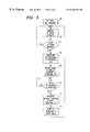
- FIG. 3 is a flow diagram illustrating an exemplary dynamic multi-step message overload control process in accordance with the present invention.
- FIG. 1 illustrates an exemplary mobile wireless communication network 2 .
- the wireless network 2 includes a mobile switching center (MSC) 4 that provides call support for plural cell base stations, including those shown by reference numerals 6 and 8 .
- MSC mobile switching center
- each base station 6 and 8 serves wireless units operating within a defined geographic area known as a cell.
- the MSC further supports a species of cell commonly referred to as a microcell (MC).
- An arrangement of cell base stations 10 1 , 10 2 . . . 10 n serves wireless units operating within these microcells.
- the microcells served by the cell base stations 10 1 , 10 2 . . . 10 n are smaller versions of the cells served by the cell base stations 6 and 8 . They are especially suited for extending wireless network coverage into high traffic areas, such as buildings, as well as sparsely populated low traffic areas.
- the cell base stations 6 , 8 and 10 1 , 10 2 . . . 10 n route voice (or data) traffic to and from wireless radio units within their respective cells via a digital cellular switch 12 , which could be implemented using a 5EDCSTM switch from Lucent Technologies, Inc.
- the switch 12 is located as part of the MSC 4 and provides a switched connection therefrom to the Public Switched Telephone network 14 . This traffic routing is illustrated by the dashed line pathways shown in FIG. 1 .
- the cell base stations also route signaling messages through the MSC 4 , and specifically through a signaling node 16 that connects to the switch 12 .
- the signaling node 16 could be implemented using the Signaling System 7 (SS 7 ) standard, and may thus be referred to as an SS 7 Node (SS 7 N).
- the MSC 4 conventionally includes a Common Node Interface (CNI) ring 18 that provides communication between a plurality of ring nodes. These include a Direct Link Node (DLN) 20 , an Administrative DLN (ACDN) 22 , and one or more Call processing Database Nodes (CDN) 24 . Also connected to the CNI ring 18 , is an Intersystem Cellular Node (ICN) 26 and a second SS 7 N 28 which provide communication between the MSC 4 and other MSCs 30 .
- CNI Common Node Interface
- ICN Intersystem Cellular Node
- a Ring Peripheral Controller Node (RPCN) 32 is further connected to the CNI ring 18 and provides a connection to an Executive Cellular Processor (ECP) 34 and an Operations and Maintenance Processor (OMP) 36 , that together control and manage the MSC 4 .
- ECP Executive Cellular Processor
- OMP Operations and Maintenance Processor
- the cell base stations 6 , 8 and 10 1 , 10 2 . . . 10 n can connect to the MSC 4 in one of two different ways. As shown in FIG. 1, the cell base stations 6 and 8 are connected using Cell Site Nodes (CSN) 38 . Among other things, the CSNs 38 route signaling messages between cell base stations 6 and 8 and the SS 7 N 16 connected to the switch 12 .
- the cell base stations 10 1 , 10 2 . . . 10 n connect to the MSC 4 in a different way. Namely, they connect to the CNI ring 18 via an Application Processor Complex (APC) 40 and an Ethernet Interface Node (EIN) 42 .
- API Application Processor Complex
- EIN Ethernet Interface Node
- the APC 40 illustrated in FIG. 1 represents a collection of APs and/or AP clusters that are interconnected to provide a network message processing environment.
- Each networked AP is a programmed computer that conventionally includes various layers of software modules functionality.
- This conventional functionality includes an ECP Complex Message Router (ECMR) that processes messages to and from other nodes on the CNI ring 18 , and a base station software (or firmware) control application that is commonly known as a Radio Cluster Server (RCS).
- ECMR ECP Complex Message Router
- RCS Radio Cluster Server
- FIG. 1 the ECMR software modules for all APs in the APC 40 are illustrated collectively by reference numeral 44 , which shall be referred to hereinafter as the ECMR 44 .
- the RCS software modules for all APs in the APC 40 are illustrated collectively by reference numeral 46 , which shall be referred to hereinafter as the RCS 46 .
- the APC 40 provides centralized call processing and operational, administrative and management functionality to support the cell base stations 10 1 , 10 2 . . . 10 n , which, by design, are constructed with smaller, less hardware-intensive radio components and fewer processing resources than the cell base stations 6 and 8 .
- a client/server network is effectively implemented in which hardware and processing redundancy are minimized by moving such resources from the cell base stations 10 1 , 10 2 . . . 10 n , which represent client nodes in the network, to the APC 40 , which acts as the network server.
- FIG. 1 shows only one APC, additional APCs could also be added to the MSC 4 , via node connections to the CNI ring 18 .
- the APC 40 can hold multiple AP Clusters (APCLs), each containing multiple APs.
- APCLs AP Clusters
- Two such APCLs are shown by reference numerals 50 and 52 , respectively.
- APCL 50 contains APs 50 1 , 50 2 . . . 50 n .
- APCL 52 contains APs 52 1 , 52 2 . . . 52 n .
- each APCL 50 and 52 would contain up to eight APs, although more could be added as necessary.
- the APCLs 50 and 52 support plural groups of cell base stations. More specifically, APCL 50 is part of a sub-network 54 in which it supports a group of cell base stations 10 1 , 10 2 . . . 10 i . Likewise, APCL 52 is part of a sub-network 56 in which it supports a group of cell base stations 10 i+l , 10 i+2 . . . 10 n .
- the APs 50 1 , 50 2 . . . 50 n and 52 1 , 52 2 . . . 52 n are programmed to perform message processing in order to provide a variety of operational, administrative and management functions on behalf of the cell base stations they serve.
- This message processing includes routing call-related messages between the cell base stations and the PSTN 14 , between the cell base stations and one or more nodes connected to the MSC 4 (or other MSCs), and between the cell base stations and other cell base stations served by the APC 40 .
- Such messages include requests for call hand-off support, home location support, paging, call set-up, call tear-down and other well known wireless communication service network functions.
- Additional messages that can be routed by the APs 50 1 , 50 2 . . . 50 n and 52 1 , 52 2 . . . 52 n include the intelligent network signaling used to implement user-specific custom calling features such as Call Forwarding, Call Waiting, Three-way Calling, Calling Line Identification and the
- the APs 50 1 , 50 2 . . . 50 n and 52 1 , 52 2 . . . 52 n are preferably programmed computers that execute software or firmware programs which implement the above-described message processing functions. As described above, each runs its own local copy of the ECMR 44 and the RCS 46 . Although not shown in FIG. 2, each AP 50 1 , 50 2 . . . 50 n and 52 1 , 52 2 . . . 52 n also maintains a network interface to a common local area network of APs that allows the APs to communicate with each other and with the EIN 42 .
- the network communication pathways 64 and 66 are part of this network.
- the base stations 10 1 , 10 2 . . . 10 n are connected to route voice (or data) traffic to the switch 12 .
- the base stations 10 1 , 10 2 . . . 10 i in the sub-network 54 are further connected to exchange messages with the APs 50 1 , through 50 n in the APCL 50 .
- the base stations 10 i+1 , 10 i+2 . . . 10 n in the sub-network are further connected to exchange messages with the APs 52 1 through 52 n in the APCL 52 .
- a switching fabric is conventionally provided between the base stations 10 1 , 10 2 . . .
- a conventional communication control module (not shown) is further provided within each AP 50 1 , 50 2 . . . 50 n and 52 1 , 52 2 . . . 52 n to process the message traffic carried over the switched connections.
- the APs 50 1 , 50 2 . . . 50 n and 52 1 , 52 2 . . . 52 n may be programmed to control their own operations in response to an AP shutdown condition, using appropriate inter-AP network communication to monitor the status of the other APs.
- a Control Processor (CP) 58 is utilized.
- the CP 58 is a programmed computer that includes a CPU (not shown) and an appropriate data storage medium 60 having a software or firmware program 62 recorded thereon for implementing the AP control functions now to be described.
- the CP 58 maintains a network interface and is connected to each APCL 50 and 52 , and to each of the APs 50 1 , 50 2 . . . 50 n and 52 1 , 52 2 . . . 52 n therein, via the network communication pathways 64 and 66 .
- Each of the APs 50 1 , 50 2 . . . 50 n and 52 1 , 52 2 . . . 52 n preferably includes a software or firmware agent, shown by reference letter “A” in FIG. 2, that provides monitoring information to, and receives control information from, the CP 58 .
- the agents also implement OLC on behalf of their respective APs in response to message processing overload conditions.
- the APCLs 50 and 52 together with the CP 58 , exemplify a message processing system in a wireless communication service network that includes at least two programmable APs providing operational, administrative and maintenance support for the one or more cell base stations, which in turn provide communication services to one or more wireless radio units.
- improved control of AP message processing resources is provided in response to an AP shutdown condition in order to promote improved load sharing among remaining operational APs and to minimize the likelihood of a catastrophic message processing failure.
- the CP 58 via its software or firmware control program 62 , provides the requisite control functions for managing AP message processing in response to an AP shutdown condition.
- the CP 58 sets an initial OLC threshold for each of the APs 50 1 , 50 2 . . . 50 n and 52 1 , 52 2 . . . 52 n by transmitting a threshold value to each AP's agent.
- a preferred operational benchmark which can be used for the OLC threshold is CPU utilization. CPU utilization is typically expressed as a percentage, with the maximum possible CPU utilization rate being 100%.
- the initial OLC threshold is normally set by the CP 58 whenever the cell base stations 10 1 , 10 2 . . . 10 n go on line and the APs 50 1 , 50 2 . . . 50 n and 52 1 , 52 2 . . . 52 n commence message processing operations.
- the AP agents use the assigned OLC threshold value to control AP operations. If the threshold is based on CPU utilization, for example, the AP agent continuously monitors CPU operations to determine whether the threshold is exceeded. If the OLC threshold is exceeded in any AP, the agent for that AP instructs the AP to begin throttling messages, e.g., by dropping them.
- step 102 the CP 58 monitors all status messages sent to it by the APs 50 1 , 50 2 . . . 50 n and 52 1 , 52 2 . . . 52 n .
- the CP 58 determines in step 104 whether the status message is a special status message indicating that there is a shutdown condition in one of the APs. If the status message is not of this type, the CP 58 loops back to step 102 to continue status message monitoring.
- a special status message may be detected in step 104 , indicating that one of the APs has become non-operational (hereinafter referred to as a non-operating AP).
- step 106 This causes the CP 58 to invoke step 106 , in which the OLC threshold relative to one or more (preferably all) of the remaining operational APs is dynamically increased. More specifically, the CP 58 instructs the agents of such APs to increase their OLC thresholds to a new level that provides sufficient processing capacity to accommodate the message processing functions of the non-operating AP.
- each cell base station 10 1 , 10 2 . . . 10 n is assigned during system initialization to one active AP and one or more alternate APs.
- the switching fabric described above is used to establish (“nail up”) switched message transmission links (e.g., DSO channels) for each connection, but only one link is actively used by a cell base station at any given time.
- Each cell base station is responsible for its own rerouting.
- the cell base stations monitor their active message transmission links and, when a failure is sensed (e.g., via a “time out” condition), the cell base stations actively linked to the non-operational AP reroute their messages on one (or more) of the pre-assigned alternate links.
- an intelligent switching fabric is employed to establish active connections between respective ones of the cell base stations 10 1 , 10 2 . . . 10 n and the APs 50 1 , 50 2 . . . 50 n and 52 1 , 52 2 . . . 52 n .
- An intelligent switching database is maintained (using APC data storage resources) that identifies cell base station/AP connection combinations.
- the intelligent switching database can be controlled by the CP 58 (or by some other processor within the APC 40 ).
- the connections to that AP fail and the intelligent switching database controller detects the failure condition. The controller then sets up new connections between the affected base stations and one or more of the remaining operational APs.
- the intelligent switching database can be populated with alternate connectivity information based on modeling to assure deterministic connections to APs that have sufficient available processing capabilities.
- Other hardware and software connection redistribution variants could also be used to redistribute messaging traffic loads in a predetermined fashion.
- step 108 Message redistribution continues in step 108 until the CP 58 detects in step 110 that the non-operating AP has returned to operational status. When this occurs, step 112 is implemented. The original message transmission connections are reestablished to the newly operational AP, and the AP begins receiving its normal allocation of messages. In addition, in step 114 , the OLC threshold for all APs is reset to the initial OLC threshold value. The AP control process then returns to step 102 to resume status message monitoring.
- the initial OLC threshold value is preferably set a low enough level to allow sufficient upward threshold adjustment following an AP shutdown so that one or more remaining operational APs in the message processing system are able to absorb the message processing functions of the non-operating AP without becoming overloaded themselves.
- the goal is to provide guaranteed service to the cell base stations 10 1 , 10 2 . . . 10 n .
- the initial OLC threshold can be determined by performance modeling or by observation of the wireless communication service network 2 during actual or simulated operations. More particularly, the initial threshold can be determined on the basis of processor utilization and message delay considerations with all APs being operational, and following the shut down of an AP with the remaining operational APs carrying an increased load.
- n is the number of total number of APs available for mutual load sharing
- n ⁇ 1 is the number of operational APs left after one of the APs fails.
- the APs 50 1 , 50 2 . . . 50 n and 52 1 , 52 2 . . . 52 n may either be paired or unpaired. If the APs 50 1 , 50 2 . . . 50 n and 52 1 , 52 2 . . . 52 n are paired, then two APs will be used to service the same group of base stations, so as to provide a measure of redundancy. If the APs 50 1 , 50 2 . . . 50 n and 52 1 , 52 2 . . . 52 n are not paired, then each AP will separately serve an assigned group of base stations. In configurations where the APs 50 1 , 50 2 . . 50 n and 52 1 , 52 2 . . . 52 n may either be paired or unpaired. If the APs 50 1 , 50 2 . . . 50 n and 52 1 , 52 2 . . . 52 n are paired,
- the OLC threshold adjustment step 106 is preferably performed by adjusting the OLC threshold for the paired mate failed AP.
- the message processing functions of the failed AP are then redistributed in step 108 to this operational AP mate.
- the OLC threshold can be adjusted in response to an overload condition for one or more (preferably all) remaining operational APs in the message processing system, or in an AP cluster therein.
- the message processing functions of the failed AP are then redistributed to these remaining operational APs.
- the following examples respectively illustrate paired AP and non-paired AP implementations of the invention.
- a message control system for a mobile wireless communication system includes at least two Application Processors (APs), and is dynamically responsive to an AP shutdown condition so as to promote improved load sharing among remaining operational APs and to minimize the likelihood of a catastrophic processing failure.
- APs Application Processors
Abstract
Description
Claims (21)
Priority Applications (1)
| Application Number | Priority Date | Filing Date | Title |
|---|---|---|---|
| US09/320,604 US6438374B1 (en) | 1999-05-26 | 1999-05-26 | Dynamic multi-step overload control for message processing in wireless communication service network |
Applications Claiming Priority (1)
| Application Number | Priority Date | Filing Date | Title |
|---|---|---|---|
| US09/320,604 US6438374B1 (en) | 1999-05-26 | 1999-05-26 | Dynamic multi-step overload control for message processing in wireless communication service network |
Publications (1)
| Publication Number | Publication Date |
|---|---|
| US6438374B1 true US6438374B1 (en) | 2002-08-20 |
Family
ID=23247145
Family Applications (1)
| Application Number | Title | Priority Date | Filing Date |
|---|---|---|---|
| US09/320,604 Expired - Lifetime US6438374B1 (en) | 1999-05-26 | 1999-05-26 | Dynamic multi-step overload control for message processing in wireless communication service network |
Country Status (1)
| Country | Link |
|---|---|
| US (1) | US6438374B1 (en) |
Cited By (16)
| Publication number | Priority date | Publication date | Assignee | Title |
|---|---|---|---|---|
| US20020004406A1 (en) * | 1995-04-13 | 2002-01-10 | Mikiya Namura | Integrated control system for radio service areas of base stations in mobile communication system |
| US20030036359A1 (en) * | 2001-07-26 | 2003-02-20 | Dent Paul W. | Mobile station loop-back signal processing |
| US6718170B1 (en) * | 1999-07-01 | 2004-04-06 | Qualcomm Incorporated | Dynamic allocation of microprocessor resources in a wireless communication device |
| US20040162082A1 (en) * | 2003-02-19 | 2004-08-19 | Inria Institut National De Recherche En Informatique Et En Automatique | Device and method for controlling admission and congestion of the configuration of a wireless communication network |
| US6785546B1 (en) * | 2000-03-16 | 2004-08-31 | Lucent Technologies Inc. | Method and apparatus for controlling application processor occupancy based traffic overload |
| US20050091002A1 (en) * | 2003-10-28 | 2005-04-28 | International Business Machines Corporation | Adjusted monitoring in a relational environment |
| US20050182969A1 (en) * | 2003-06-09 | 2005-08-18 | Andrew Ginter | Periodic filesystem integrity checks |
| US20060062148A1 (en) * | 2004-09-22 | 2006-03-23 | Nec Corporation | System utilization rate managing apparatus and system utilization rate managing method to be employed for it, and its program |
| US7151929B1 (en) * | 2000-08-18 | 2006-12-19 | Northrop Grumman Corporation | Satellite payload data communications and processing techniques |
| US20070153751A1 (en) * | 2005-12-30 | 2007-07-05 | Svensson Sven Anders B | PDSN-based session recovery from RBS/AN failure in a distributed architecture network |
| US7546120B1 (en) | 2005-10-14 | 2009-06-09 | Sprint Spectrum L.P. | Method and system for managing transmission of media to multiple subscribers |
| EP2129175A1 (en) * | 2008-05-28 | 2009-12-02 | Alcatel, Lucent | Method of detecting an outage of a radio cell |
| US7689223B1 (en) | 2003-06-05 | 2010-03-30 | Sprint Spectrum L.P. | Method and system for delaying retransmission of data traffic to a wireless terminal |
| US20110038649A1 (en) * | 2008-06-10 | 2011-02-17 | Canon Kabushiki Kaisha | Cartridge, and electrophotographic image forming apparatus which uses cartridge |
| US20120026870A1 (en) * | 2009-12-18 | 2012-02-02 | Hewlett-Packard Development Company, L.P. | Proxy agents in a network |
| US20120096045A1 (en) * | 2010-10-19 | 2012-04-19 | Moore Tiffany A | System and method for traffic surge control |
Citations (10)
| Publication number | Priority date | Publication date | Assignee | Title |
|---|---|---|---|---|
| US5513255A (en) * | 1993-12-11 | 1996-04-30 | Electronics And Telecommunication Research Institute | Method for controlling overload of distributed processors of full electronic switching system |
| US5539815A (en) * | 1995-02-24 | 1996-07-23 | At&T Corp. | Network call routing controlled by a management node |
| US5548533A (en) * | 1994-10-07 | 1996-08-20 | Northern Telecom Limited | Overload control for a central processor in the switching network of a mobile communications system |
| US5655120A (en) * | 1993-09-24 | 1997-08-05 | Siemens Aktiengesellschaft | Method for load balancing in a multi-processor system where arising jobs are processed by a plurality of processors under real-time conditions |
| US5892818A (en) * | 1995-05-27 | 1999-04-06 | Samsung Electronics Co., Ltd. | Method of controlling message overload on a program in a plural processor controlled switching system |
| US5943232A (en) * | 1997-10-29 | 1999-08-24 | Lucent Technologies Inc. | Autonomous overload control for distributed real time systems |
| US6259776B1 (en) * | 1997-03-25 | 2001-07-10 | British Telecommunications Public Limited Company | System for controlling telecommunication overload traffic |
| US6266531B1 (en) * | 1998-07-01 | 2001-07-24 | Ericsson Inc. | System and method for adaptive thresholds for cell load sharing |
| US6336034B1 (en) * | 1995-04-13 | 2002-01-01 | Hiatchi, Ltd. | Integrated control system for radio service areas of base stations in mobile communication system |
| US6356629B1 (en) * | 1999-02-02 | 2002-03-12 | Cisco Technology, Inc. | Switched virtual circuit controller setup congestion management strategy |
-
1999
- 1999-05-26 US US09/320,604 patent/US6438374B1/en not_active Expired - Lifetime
Patent Citations (10)
| Publication number | Priority date | Publication date | Assignee | Title |
|---|---|---|---|---|
| US5655120A (en) * | 1993-09-24 | 1997-08-05 | Siemens Aktiengesellschaft | Method for load balancing in a multi-processor system where arising jobs are processed by a plurality of processors under real-time conditions |
| US5513255A (en) * | 1993-12-11 | 1996-04-30 | Electronics And Telecommunication Research Institute | Method for controlling overload of distributed processors of full electronic switching system |
| US5548533A (en) * | 1994-10-07 | 1996-08-20 | Northern Telecom Limited | Overload control for a central processor in the switching network of a mobile communications system |
| US5539815A (en) * | 1995-02-24 | 1996-07-23 | At&T Corp. | Network call routing controlled by a management node |
| US6336034B1 (en) * | 1995-04-13 | 2002-01-01 | Hiatchi, Ltd. | Integrated control system for radio service areas of base stations in mobile communication system |
| US5892818A (en) * | 1995-05-27 | 1999-04-06 | Samsung Electronics Co., Ltd. | Method of controlling message overload on a program in a plural processor controlled switching system |
| US6259776B1 (en) * | 1997-03-25 | 2001-07-10 | British Telecommunications Public Limited Company | System for controlling telecommunication overload traffic |
| US5943232A (en) * | 1997-10-29 | 1999-08-24 | Lucent Technologies Inc. | Autonomous overload control for distributed real time systems |
| US6266531B1 (en) * | 1998-07-01 | 2001-07-24 | Ericsson Inc. | System and method for adaptive thresholds for cell load sharing |
| US6356629B1 (en) * | 1999-02-02 | 2002-03-12 | Cisco Technology, Inc. | Switched virtual circuit controller setup congestion management strategy |
Cited By (28)
| Publication number | Priority date | Publication date | Assignee | Title |
|---|---|---|---|---|
| US6839558B2 (en) * | 1995-04-13 | 2005-01-04 | Hitachi, Ltd. | Integrated control system for radio service areas of base stations in mobile communication system |
| US20020004406A1 (en) * | 1995-04-13 | 2002-01-10 | Mikiya Namura | Integrated control system for radio service areas of base stations in mobile communication system |
| US6718170B1 (en) * | 1999-07-01 | 2004-04-06 | Qualcomm Incorporated | Dynamic allocation of microprocessor resources in a wireless communication device |
| US6785546B1 (en) * | 2000-03-16 | 2004-08-31 | Lucent Technologies Inc. | Method and apparatus for controlling application processor occupancy based traffic overload |
| US7151929B1 (en) * | 2000-08-18 | 2006-12-19 | Northrop Grumman Corporation | Satellite payload data communications and processing techniques |
| US7197282B2 (en) * | 2001-07-26 | 2007-03-27 | Ericsson Inc. | Mobile station loop-back signal processing |
| US20030036359A1 (en) * | 2001-07-26 | 2003-02-20 | Dent Paul W. | Mobile station loop-back signal processing |
| US20040162082A1 (en) * | 2003-02-19 | 2004-08-19 | Inria Institut National De Recherche En Informatique Et En Automatique | Device and method for controlling admission and congestion of the configuration of a wireless communication network |
| US7317922B2 (en) * | 2003-02-19 | 2008-01-08 | Inria Institut National De Recherche En Informatique Et En Automatique | Device and method for controlling admission and congestion of the configuration of a wireless communication network |
| US7689223B1 (en) | 2003-06-05 | 2010-03-30 | Sprint Spectrum L.P. | Method and system for delaying retransmission of data traffic to a wireless terminal |
| US20050182969A1 (en) * | 2003-06-09 | 2005-08-18 | Andrew Ginter | Periodic filesystem integrity checks |
| US20050091002A1 (en) * | 2003-10-28 | 2005-04-28 | International Business Machines Corporation | Adjusted monitoring in a relational environment |
| US6993453B2 (en) | 2003-10-28 | 2006-01-31 | International Business Machines Corporation | Adjusted monitoring in a relational environment |
| US7864679B2 (en) * | 2004-09-22 | 2011-01-04 | Nec Corporation | System utilization rate managing apparatus and system utilization rate managing method to be employed for it, and its program |
| US20060062148A1 (en) * | 2004-09-22 | 2006-03-23 | Nec Corporation | System utilization rate managing apparatus and system utilization rate managing method to be employed for it, and its program |
| US7546120B1 (en) | 2005-10-14 | 2009-06-09 | Sprint Spectrum L.P. | Method and system for managing transmission of media to multiple subscribers |
| US20070153751A1 (en) * | 2005-12-30 | 2007-07-05 | Svensson Sven Anders B | PDSN-based session recovery from RBS/AN failure in a distributed architecture network |
| US8130719B2 (en) * | 2005-12-30 | 2012-03-06 | Telefonaktiebolaget Lm Ericsson (Publ) | PDSN-based session recovery from RBS/AN failure in a distributed architecture network |
| EP2129175A1 (en) * | 2008-05-28 | 2009-12-02 | Alcatel, Lucent | Method of detecting an outage of a radio cell |
| US20110038649A1 (en) * | 2008-06-10 | 2011-02-17 | Canon Kabushiki Kaisha | Cartridge, and electrophotographic image forming apparatus which uses cartridge |
| US10168665B2 (en) | 2008-06-10 | 2019-01-01 | Canon Kabushiki Kaisha | Cartridge, and electrophotographic image forming apparatus which uses cartridge |
| US11061369B2 (en) | 2008-06-10 | 2021-07-13 | Canon Kabushiki Kaisha | Cartridge and electrophotographic image forming apparatus which uses cartridge |
| US11067949B2 (en) | 2008-06-10 | 2021-07-20 | Canon Kabushiki Kaisha | Cartridge and electrophotographic image forming apparatus which uses cartridge |
| US11500327B2 (en) | 2008-06-10 | 2022-11-15 | Canon Kabushiki Kaisha | Cartridge and electrophotographic image forming apparatus which uses cartridge |
| US20120026870A1 (en) * | 2009-12-18 | 2012-02-02 | Hewlett-Packard Development Company, L.P. | Proxy agents in a network |
| US8634321B2 (en) * | 2009-12-18 | 2014-01-21 | Hewlett-Packard Development Company, L.P. | Proxy agents in a network |
| US20120096045A1 (en) * | 2010-10-19 | 2012-04-19 | Moore Tiffany A | System and method for traffic surge control |
| US8972455B2 (en) * | 2010-10-19 | 2015-03-03 | Hewlett-Packard Development Company, L.P. | System and method for traffic surge control |
Similar Documents
| Publication | Publication Date | Title |
|---|---|---|
| US6574477B1 (en) | Dynamic load balancing during message processing in a wireless communication service network | |
| US6438374B1 (en) | Dynamic multi-step overload control for message processing in wireless communication service network | |
| US6738625B1 (en) | Rehoming and resource sharing in communications networks | |
| EP1589773B1 (en) | Centralized cell homing and load balancing in a base station controller | |
| US6385449B2 (en) | System and method used in a mobile telecommunications network for load balancing ongoing calls between different base station controllers | |
| US7580716B2 (en) | Method and apparatus for load balancing in a wireless network | |
| EP2064906B1 (en) | Method for recovering connectivity in the event of a failure in a radio communications system and controlling node thereof | |
| WO2008030171A2 (en) | Non-homogenous telecommunications base stations | |
| US6577871B1 (en) | Technique for effectively managing processing loads in a communications arrangement | |
| US20020137518A1 (en) | System and method for minimizing hardware and maximizing capacity in a wireless communications system | |
| US6129604A (en) | Dynamic load distribution in a wireless communication system to equalize loading on mobile switching centers | |
| US6064892A (en) | Traffic management system with overload control functions for use in a telecommunications system | |
| US9654991B2 (en) | Radio property based access point load balancing in controller cluster | |
| US20040244001A1 (en) | Methods of allocating use of multiple resources in a system | |
| JP3996096B2 (en) | Wireless LAN communication system | |
| JP3789354B2 (en) | Base station controller load balancing method | |
| EP2375803B1 (en) | Multi-mode Radio Access Network controller entity with dynamic re-configuration for supporting at least two different radio access technologies | |
| JP2008124799A (en) | Radio base control station and routing method | |
| US20020131409A1 (en) | Self-healing multi-level telecommunications network | |
| JP2003018068A (en) | Cdma system and method for detecting faulty mobile unit | |
| EP1040684A1 (en) | Method for maintaining reliability in a service network | |
| US5970416A (en) | Provision of distributed call handling over a plurality of network nodes | |
| US5708962A (en) | Method of reconfiguring a distributed communication system using allocation loading level | |
| US20050198022A1 (en) | Apparatus and method using proxy objects for application resource management in a communication network | |
| US8059567B1 (en) | Distributing mobile stations across carriers of plural frequency bands |
Legal Events
| Date | Code | Title | Description |
|---|---|---|---|
| AS | Assignment |
Owner name: LUCENT TECHNOLOGIES INC., NEW JERSEY Free format text: ASSIGNMENT OF ASSIGNORS INTEREST;ASSIGNOR:BHAT, KABEKODE VENKATA;REEL/FRAME:009998/0109 Effective date: 19990525 |
|
| STCF | Information on status: patent grant |
Free format text: PATENTED CASE |
|
| FPAY | Fee payment |
Year of fee payment: 4 |
|
| FEPP | Fee payment procedure |
Free format text: PAYOR NUMBER ASSIGNED (ORIGINAL EVENT CODE: ASPN); ENTITY STATUS OF PATENT OWNER: LARGE ENTITY |
|
| FPAY | Fee payment |
Year of fee payment: 8 |
|
| FPAY | Fee payment |
Year of fee payment: 12 |
|
| AS | Assignment |
Owner name: PROVENANCE ASSET GROUP LLC, CONNECTICUT Free format text: ASSIGNMENT OF ASSIGNORS INTEREST;ASSIGNORS:NOKIA TECHNOLOGIES OY;NOKIA SOLUTIONS AND NETWORKS BV;ALCATEL LUCENT SAS;REEL/FRAME:043877/0001 Effective date: 20170912 Owner name: NOKIA USA INC., CALIFORNIA Free format text: SECURITY INTEREST;ASSIGNORS:PROVENANCE ASSET GROUP HOLDINGS, LLC;PROVENANCE ASSET GROUP LLC;REEL/FRAME:043879/0001 Effective date: 20170913 Owner name: CORTLAND CAPITAL MARKET SERVICES, LLC, ILLINOIS Free format text: SECURITY INTEREST;ASSIGNORS:PROVENANCE ASSET GROUP HOLDINGS, LLC;PROVENANCE ASSET GROUP, LLC;REEL/FRAME:043967/0001 Effective date: 20170913 |
|
| AS | Assignment |
Owner name: ALCATEL-LUCENT USA INC., NEW JERSEY Free format text: CHANGE OF NAME;ASSIGNOR:LUCENT TECHNOLOGIES INC.;REEL/FRAME:049887/0613 Effective date: 20081101 |
|
| AS | Assignment |
Owner name: NOKIA US HOLDINGS INC., NEW JERSEY Free format text: ASSIGNMENT AND ASSUMPTION AGREEMENT;ASSIGNOR:NOKIA USA INC.;REEL/FRAME:048370/0682 Effective date: 20181220 |
|
| AS | Assignment |
Owner name: PROVENANCE ASSET GROUP LLC, CONNECTICUT Free format text: RELEASE BY SECURED PARTY;ASSIGNOR:CORTLAND CAPITAL MARKETS SERVICES LLC;REEL/FRAME:058983/0104 Effective date: 20211101 Owner name: PROVENANCE ASSET GROUP HOLDINGS LLC, CONNECTICUT Free format text: RELEASE BY SECURED PARTY;ASSIGNOR:CORTLAND CAPITAL MARKETS SERVICES LLC;REEL/FRAME:058983/0104 Effective date: 20211101 Owner name: PROVENANCE ASSET GROUP LLC, CONNECTICUT Free format text: RELEASE BY SECURED PARTY;ASSIGNOR:NOKIA US HOLDINGS INC.;REEL/FRAME:058363/0723 Effective date: 20211129 Owner name: PROVENANCE ASSET GROUP HOLDINGS LLC, CONNECTICUT Free format text: RELEASE BY SECURED PARTY;ASSIGNOR:NOKIA US HOLDINGS INC.;REEL/FRAME:058363/0723 Effective date: 20211129 |
|
| AS | Assignment |
Owner name: RPX CORPORATION, CALIFORNIA Free format text: ASSIGNMENT OF ASSIGNORS INTEREST;ASSIGNOR:PROVENANCE ASSET GROUP LLC;REEL/FRAME:059352/0001 Effective date: 20211129 |