US6443929B1 - Needle tip guard for hypodermic needles - Google Patents
Needle tip guard for hypodermic needles Download PDFInfo
- Publication number
- US6443929B1 US6443929B1 US09/144,398 US14439898A US6443929B1 US 6443929 B1 US6443929 B1 US 6443929B1 US 14439898 A US14439898 A US 14439898A US 6443929 B1 US6443929 B1 US 6443929B1
- Authority
- US
- United States
- Prior art keywords
- needle
- needle guard
- hub
- guard
- trap
- Prior art date
- Legal status (The legal status is an assumption and is not a legal conclusion. Google has not performed a legal analysis and makes no representation as to the accuracy of the status listed.)
- Expired - Lifetime
Links
Images


Classifications
-
- A—HUMAN NECESSITIES
- A61—MEDICAL OR VETERINARY SCIENCE; HYGIENE
- A61B—DIAGNOSIS; SURGERY; IDENTIFICATION
- A61B5/00—Measuring for diagnostic purposes; Identification of persons
- A61B5/15—Devices for taking samples of blood
- A61B5/150007—Details
- A61B5/150015—Source of blood
- A61B5/15003—Source of blood for venous or arterial blood
-
- A—HUMAN NECESSITIES
- A61—MEDICAL OR VETERINARY SCIENCE; HYGIENE
- A61M—DEVICES FOR INTRODUCING MEDIA INTO, OR ONTO, THE BODY; DEVICES FOR TRANSDUCING BODY MEDIA OR FOR TAKING MEDIA FROM THE BODY; DEVICES FOR PRODUCING OR ENDING SLEEP OR STUPOR
- A61M5/00—Devices for bringing media into the body in a subcutaneous, intra-vascular or intramuscular way; Accessories therefor, e.g. filling or cleaning devices, arm-rests
-
- A—HUMAN NECESSITIES
- A61—MEDICAL OR VETERINARY SCIENCE; HYGIENE
- A61B—DIAGNOSIS; SURGERY; IDENTIFICATION
- A61B5/00—Measuring for diagnostic purposes; Identification of persons
- A61B5/15—Devices for taking samples of blood
- A61B5/150007—Details
- A61B5/150374—Details of piercing elements or protective means for preventing accidental injuries by such piercing elements
- A61B5/150381—Design of piercing elements
- A61B5/150389—Hollow piercing elements, e.g. canulas, needles, for piercing the skin
-
- A—HUMAN NECESSITIES
- A61—MEDICAL OR VETERINARY SCIENCE; HYGIENE
- A61B—DIAGNOSIS; SURGERY; IDENTIFICATION
- A61B5/00—Measuring for diagnostic purposes; Identification of persons
- A61B5/15—Devices for taking samples of blood
- A61B5/150007—Details
- A61B5/150374—Details of piercing elements or protective means for preventing accidental injuries by such piercing elements
- A61B5/150381—Design of piercing elements
- A61B5/150473—Double-ended needles, e.g. used with pre-evacuated sampling tubes
- A61B5/150488—Details of construction of shaft
-
- A—HUMAN NECESSITIES
- A61—MEDICAL OR VETERINARY SCIENCE; HYGIENE
- A61B—DIAGNOSIS; SURGERY; IDENTIFICATION
- A61B5/00—Measuring for diagnostic purposes; Identification of persons
- A61B5/15—Devices for taking samples of blood
- A61B5/150007—Details
- A61B5/150374—Details of piercing elements or protective means for preventing accidental injuries by such piercing elements
- A61B5/150381—Design of piercing elements
- A61B5/150473—Double-ended needles, e.g. used with pre-evacuated sampling tubes
- A61B5/150496—Details of construction of hub, i.e. element used to attach the double-ended needle to a piercing device or sampling device
-
- A—HUMAN NECESSITIES
- A61—MEDICAL OR VETERINARY SCIENCE; HYGIENE
- A61B—DIAGNOSIS; SURGERY; IDENTIFICATION
- A61B5/00—Measuring for diagnostic purposes; Identification of persons
- A61B5/15—Devices for taking samples of blood
- A61B5/150007—Details
- A61B5/150374—Details of piercing elements or protective means for preventing accidental injuries by such piercing elements
- A61B5/150534—Design of protective means for piercing elements for preventing accidental needle sticks, e.g. shields, caps, protectors, axially extensible sleeves, pivotable protective sleeves
- A61B5/150572—Pierceable protectors, e.g. shields, caps, sleeves or films, e.g. for hygienic purposes
-
- A—HUMAN NECESSITIES
- A61—MEDICAL OR VETERINARY SCIENCE; HYGIENE
- A61B—DIAGNOSIS; SURGERY; IDENTIFICATION
- A61B5/00—Measuring for diagnostic purposes; Identification of persons
- A61B5/15—Devices for taking samples of blood
- A61B5/150007—Details
- A61B5/150374—Details of piercing elements or protective means for preventing accidental injuries by such piercing elements
- A61B5/150534—Design of protective means for piercing elements for preventing accidental needle sticks, e.g. shields, caps, protectors, axially extensible sleeves, pivotable protective sleeves
- A61B5/150633—Protective sleeves which are axially extensible, e.g. sleeves connected to, or integrated in, the piercing or driving device; pivotable protective sleeves
- A61B5/150641—Protective sleeves which are axially extensible, e.g. sleeves connected to, or integrated in, the piercing or driving device; pivotable protective sleeves comprising means to impede repositioning of protection sleeve from covering to uncovering position
-
- A—HUMAN NECESSITIES
- A61—MEDICAL OR VETERINARY SCIENCE; HYGIENE
- A61B—DIAGNOSIS; SURGERY; IDENTIFICATION
- A61B5/00—Measuring for diagnostic purposes; Identification of persons
- A61B5/15—Devices for taking samples of blood
- A61B5/150007—Details
- A61B5/150732—Needle holders, for instance for holding the needle by the hub, used for example with double-ended needle and pre-evacuated tube
-
- A—HUMAN NECESSITIES
- A61—MEDICAL OR VETERINARY SCIENCE; HYGIENE
- A61B—DIAGNOSIS; SURGERY; IDENTIFICATION
- A61B5/00—Measuring for diagnostic purposes; Identification of persons
- A61B5/15—Devices for taking samples of blood
- A61B5/153—Devices specially adapted for taking samples of venous or arterial blood, e.g. with syringes
- A61B5/154—Devices using pre-evacuated means
-
- A—HUMAN NECESSITIES
- A61—MEDICAL OR VETERINARY SCIENCE; HYGIENE
- A61M—DEVICES FOR INTRODUCING MEDIA INTO, OR ONTO, THE BODY; DEVICES FOR TRANSDUCING BODY MEDIA OR FOR TAKING MEDIA FROM THE BODY; DEVICES FOR PRODUCING OR ENDING SLEEP OR STUPOR
- A61M25/00—Catheters; Hollow probes
- A61M25/01—Introducing, guiding, advancing, emplacing or holding catheters
- A61M25/06—Body-piercing guide needles or the like
- A61M25/0612—Devices for protecting the needle; Devices to help insertion of the needle, e.g. wings or holders
- A61M25/0618—Devices for protecting the needle; Devices to help insertion of the needle, e.g. wings or holders having means for protecting only the distal tip of the needle, e.g. a needle guard
- A61M25/0625—Devices for protecting the needle; Devices to help insertion of the needle, e.g. wings or holders having means for protecting only the distal tip of the needle, e.g. a needle guard with a permanent connection to the needle hub, e.g. a guiding rail, a locking mechanism or a guard advancement mechanism
-
- A—HUMAN NECESSITIES
- A61—MEDICAL OR VETERINARY SCIENCE; HYGIENE
- A61M—DEVICES FOR INTRODUCING MEDIA INTO, OR ONTO, THE BODY; DEVICES FOR TRANSDUCING BODY MEDIA OR FOR TAKING MEDIA FROM THE BODY; DEVICES FOR PRODUCING OR ENDING SLEEP OR STUPOR
- A61M5/00—Devices for bringing media into the body in a subcutaneous, intra-vascular or intramuscular way; Accessories therefor, e.g. filling or cleaning devices, arm-rests
- A61M5/178—Syringes
- A61M5/31—Details
- A61M5/32—Needles; Details of needles pertaining to their connection with syringe or hub; Accessories for bringing the needle into, or holding the needle on, the body; Devices for protection of needles
- A61M5/3205—Apparatus for removing or disposing of used needles or syringes, e.g. containers; Means for protection against accidental injuries from used needles
- A61M5/321—Means for protection against accidental injuries by used needles
- A61M5/3243—Means for protection against accidental injuries by used needles being axially-extensible, e.g. protective sleeves coaxially slidable on the syringe barrel
- A61M5/3273—Means for protection against accidental injuries by used needles being axially-extensible, e.g. protective sleeves coaxially slidable on the syringe barrel freely sliding on needle shaft without connection to syringe or needle
-
- A—HUMAN NECESSITIES
- A61—MEDICAL OR VETERINARY SCIENCE; HYGIENE
- A61M—DEVICES FOR INTRODUCING MEDIA INTO, OR ONTO, THE BODY; DEVICES FOR TRANSDUCING BODY MEDIA OR FOR TAKING MEDIA FROM THE BODY; DEVICES FOR PRODUCING OR ENDING SLEEP OR STUPOR
- A61M5/00—Devices for bringing media into the body in a subcutaneous, intra-vascular or intramuscular way; Accessories therefor, e.g. filling or cleaning devices, arm-rests
- A61M5/178—Syringes
- A61M5/31—Details
- A61M5/32—Needles; Details of needles pertaining to their connection with syringe or hub; Accessories for bringing the needle into, or holding the needle on, the body; Devices for protection of needles
- A61M5/3205—Apparatus for removing or disposing of used needles or syringes, e.g. containers; Means for protection against accidental injuries from used needles
- A61M5/321—Means for protection against accidental injuries by used needles
- A61M5/3243—Means for protection against accidental injuries by used needles being axially-extensible, e.g. protective sleeves coaxially slidable on the syringe barrel
- A61M5/3275—Means for protection against accidental injuries by used needles being axially-extensible, e.g. protective sleeves coaxially slidable on the syringe barrel being connected to the needle hub or syringe by radially deflectable members, e.g. longitudinal slats, cords or bands
-
- A—HUMAN NECESSITIES
- A61—MEDICAL OR VETERINARY SCIENCE; HYGIENE
- A61M—DEVICES FOR INTRODUCING MEDIA INTO, OR ONTO, THE BODY; DEVICES FOR TRANSDUCING BODY MEDIA OR FOR TAKING MEDIA FROM THE BODY; DEVICES FOR PRODUCING OR ENDING SLEEP OR STUPOR
- A61M5/00—Devices for bringing media into the body in a subcutaneous, intra-vascular or intramuscular way; Accessories therefor, e.g. filling or cleaning devices, arm-rests
- A61M5/178—Syringes
- A61M5/24—Ampoule syringes, i.e. syringes with needle for use in combination with replaceable ampoules or carpules, e.g. automatic
- A61M2005/2403—Ampoule inserted into the ampoule holder
- A61M2005/2414—Ampoule inserted into the ampoule holder from the side
-
- A—HUMAN NECESSITIES
- A61—MEDICAL OR VETERINARY SCIENCE; HYGIENE
- A61M—DEVICES FOR INTRODUCING MEDIA INTO, OR ONTO, THE BODY; DEVICES FOR TRANSDUCING BODY MEDIA OR FOR TAKING MEDIA FROM THE BODY; DEVICES FOR PRODUCING OR ENDING SLEEP OR STUPOR
- A61M5/00—Devices for bringing media into the body in a subcutaneous, intra-vascular or intramuscular way; Accessories therefor, e.g. filling or cleaning devices, arm-rests
- A61M5/178—Syringes
- A61M5/31—Details
- A61M2005/3103—Leak prevention means for distal end of syringes, i.e. syringe end for mounting a needle
- A61M2005/3107—Leak prevention means for distal end of syringes, i.e. syringe end for mounting a needle for needles
- A61M2005/3109—Caps sealing the needle bore by use of, e.g. air-hardening adhesive, elastomer or epoxy resin
-
- A—HUMAN NECESSITIES
- A61—MEDICAL OR VETERINARY SCIENCE; HYGIENE
- A61M—DEVICES FOR INTRODUCING MEDIA INTO, OR ONTO, THE BODY; DEVICES FOR TRANSDUCING BODY MEDIA OR FOR TAKING MEDIA FROM THE BODY; DEVICES FOR PRODUCING OR ENDING SLEEP OR STUPOR
- A61M5/00—Devices for bringing media into the body in a subcutaneous, intra-vascular or intramuscular way; Accessories therefor, e.g. filling or cleaning devices, arm-rests
- A61M5/178—Syringes
- A61M5/31—Details
- A61M5/32—Needles; Details of needles pertaining to their connection with syringe or hub; Accessories for bringing the needle into, or holding the needle on, the body; Devices for protection of needles
- A61M5/3205—Apparatus for removing or disposing of used needles or syringes, e.g. containers; Means for protection against accidental injuries from used needles
- A61M5/321—Means for protection against accidental injuries by used needles
- A61M5/3243—Means for protection against accidental injuries by used needles being axially-extensible, e.g. protective sleeves coaxially slidable on the syringe barrel
- A61M5/3245—Constructional features thereof, e.g. to improve manipulation or functioning
- A61M2005/3246—Constructional features thereof, e.g. to improve manipulation or functioning being squeezably deformable for locking or unlocking purposes, e.g. with elliptical cross-section
-
- A—HUMAN NECESSITIES
- A61—MEDICAL OR VETERINARY SCIENCE; HYGIENE
- A61M—DEVICES FOR INTRODUCING MEDIA INTO, OR ONTO, THE BODY; DEVICES FOR TRANSDUCING BODY MEDIA OR FOR TAKING MEDIA FROM THE BODY; DEVICES FOR PRODUCING OR ENDING SLEEP OR STUPOR
- A61M5/00—Devices for bringing media into the body in a subcutaneous, intra-vascular or intramuscular way; Accessories therefor, e.g. filling or cleaning devices, arm-rests
- A61M5/178—Syringes
- A61M5/31—Details
- A61M5/32—Needles; Details of needles pertaining to their connection with syringe or hub; Accessories for bringing the needle into, or holding the needle on, the body; Devices for protection of needles
- A61M5/3205—Apparatus for removing or disposing of used needles or syringes, e.g. containers; Means for protection against accidental injuries from used needles
- A61M5/321—Means for protection against accidental injuries by used needles
- A61M5/3243—Means for protection against accidental injuries by used needles being axially-extensible, e.g. protective sleeves coaxially slidable on the syringe barrel
- A61M5/3245—Constructional features thereof, e.g. to improve manipulation or functioning
- A61M2005/3247—Means to impede repositioning of protection sleeve from needle covering to needle uncovering position
- A61M2005/325—Means obstructing the needle passage at distal end of a needle protection sleeve
-
- A—HUMAN NECESSITIES
- A61—MEDICAL OR VETERINARY SCIENCE; HYGIENE
- A61M—DEVICES FOR INTRODUCING MEDIA INTO, OR ONTO, THE BODY; DEVICES FOR TRANSDUCING BODY MEDIA OR FOR TAKING MEDIA FROM THE BODY; DEVICES FOR PRODUCING OR ENDING SLEEP OR STUPOR
- A61M2205/00—General characteristics of the apparatus
- A61M2205/58—Means for facilitating use, e.g. by people with impaired vision
- A61M2205/583—Means for facilitating use, e.g. by people with impaired vision by visual feedback
-
- A—HUMAN NECESSITIES
- A61—MEDICAL OR VETERINARY SCIENCE; HYGIENE
- A61M—DEVICES FOR INTRODUCING MEDIA INTO, OR ONTO, THE BODY; DEVICES FOR TRANSDUCING BODY MEDIA OR FOR TAKING MEDIA FROM THE BODY; DEVICES FOR PRODUCING OR ENDING SLEEP OR STUPOR
- A61M25/00—Catheters; Hollow probes
- A61M25/01—Introducing, guiding, advancing, emplacing or holding catheters
- A61M25/06—Body-piercing guide needles or the like
- A61M25/0606—"Over-the-needle" catheter assemblies, e.g. I.V. catheters
-
- A—HUMAN NECESSITIES
- A61—MEDICAL OR VETERINARY SCIENCE; HYGIENE
- A61M—DEVICES FOR INTRODUCING MEDIA INTO, OR ONTO, THE BODY; DEVICES FOR TRANSDUCING BODY MEDIA OR FOR TAKING MEDIA FROM THE BODY; DEVICES FOR PRODUCING OR ENDING SLEEP OR STUPOR
- A61M25/00—Catheters; Hollow probes
- A61M25/01—Introducing, guiding, advancing, emplacing or holding catheters
- A61M25/06—Body-piercing guide needles or the like
- A61M25/0612—Devices for protecting the needle; Devices to help insertion of the needle, e.g. wings or holders
-
- A—HUMAN NECESSITIES
- A61—MEDICAL OR VETERINARY SCIENCE; HYGIENE
- A61M—DEVICES FOR INTRODUCING MEDIA INTO, OR ONTO, THE BODY; DEVICES FOR TRANSDUCING BODY MEDIA OR FOR TAKING MEDIA FROM THE BODY; DEVICES FOR PRODUCING OR ENDING SLEEP OR STUPOR
- A61M5/00—Devices for bringing media into the body in a subcutaneous, intra-vascular or intramuscular way; Accessories therefor, e.g. filling or cleaning devices, arm-rests
- A61M5/002—Packages specially adapted therefor, e.g. for syringes or needles, kits for diabetics
-
- A—HUMAN NECESSITIES
- A61—MEDICAL OR VETERINARY SCIENCE; HYGIENE
- A61M—DEVICES FOR INTRODUCING MEDIA INTO, OR ONTO, THE BODY; DEVICES FOR TRANSDUCING BODY MEDIA OR FOR TAKING MEDIA FROM THE BODY; DEVICES FOR PRODUCING OR ENDING SLEEP OR STUPOR
- A61M5/00—Devices for bringing media into the body in a subcutaneous, intra-vascular or intramuscular way; Accessories therefor, e.g. filling or cleaning devices, arm-rests
- A61M5/178—Syringes
- A61M5/24—Ampoule syringes, i.e. syringes with needle for use in combination with replaceable ampoules or carpules, e.g. automatic
-
- A—HUMAN NECESSITIES
- A61—MEDICAL OR VETERINARY SCIENCE; HYGIENE
- A61M—DEVICES FOR INTRODUCING MEDIA INTO, OR ONTO, THE BODY; DEVICES FOR TRANSDUCING BODY MEDIA OR FOR TAKING MEDIA FROM THE BODY; DEVICES FOR PRODUCING OR ENDING SLEEP OR STUPOR
- A61M5/00—Devices for bringing media into the body in a subcutaneous, intra-vascular or intramuscular way; Accessories therefor, e.g. filling or cleaning devices, arm-rests
- A61M5/178—Syringes
- A61M5/31—Details
- A61M5/32—Needles; Details of needles pertaining to their connection with syringe or hub; Accessories for bringing the needle into, or holding the needle on, the body; Devices for protection of needles
- A61M5/3202—Devices for protection of the needle before use, e.g. caps
-
- A—HUMAN NECESSITIES
- A61—MEDICAL OR VETERINARY SCIENCE; HYGIENE
- A61M—DEVICES FOR INTRODUCING MEDIA INTO, OR ONTO, THE BODY; DEVICES FOR TRANSDUCING BODY MEDIA OR FOR TAKING MEDIA FROM THE BODY; DEVICES FOR PRODUCING OR ENDING SLEEP OR STUPOR
- A61M5/00—Devices for bringing media into the body in a subcutaneous, intra-vascular or intramuscular way; Accessories therefor, e.g. filling or cleaning devices, arm-rests
- A61M5/178—Syringes
- A61M5/31—Details
- A61M5/32—Needles; Details of needles pertaining to their connection with syringe or hub; Accessories for bringing the needle into, or holding the needle on, the body; Devices for protection of needles
- A61M5/3205—Apparatus for removing or disposing of used needles or syringes, e.g. containers; Means for protection against accidental injuries from used needles
- A61M5/321—Means for protection against accidental injuries by used needles
- A61M5/3243—Means for protection against accidental injuries by used needles being axially-extensible, e.g. protective sleeves coaxially slidable on the syringe barrel
- A61M5/3257—Semi-automatic sleeve extension, i.e. in which triggering of the sleeve extension requires a deliberate action by the user, e.g. manual release of spring-biased extension means
-
- A—HUMAN NECESSITIES
- A61—MEDICAL OR VETERINARY SCIENCE; HYGIENE
- A61M—DEVICES FOR INTRODUCING MEDIA INTO, OR ONTO, THE BODY; DEVICES FOR TRANSDUCING BODY MEDIA OR FOR TAKING MEDIA FROM THE BODY; DEVICES FOR PRODUCING OR ENDING SLEEP OR STUPOR
- A61M5/00—Devices for bringing media into the body in a subcutaneous, intra-vascular or intramuscular way; Accessories therefor, e.g. filling or cleaning devices, arm-rests
- A61M5/178—Syringes
- A61M5/31—Details
- A61M5/32—Needles; Details of needles pertaining to their connection with syringe or hub; Accessories for bringing the needle into, or holding the needle on, the body; Devices for protection of needles
- A61M5/329—Needles; Details of needles pertaining to their connection with syringe or hub; Accessories for bringing the needle into, or holding the needle on, the body; Devices for protection of needles characterised by features of the needle shaft
- A61M5/3291—Shafts with additional lateral openings
-
- Y—GENERAL TAGGING OF NEW TECHNOLOGICAL DEVELOPMENTS; GENERAL TAGGING OF CROSS-SECTIONAL TECHNOLOGIES SPANNING OVER SEVERAL SECTIONS OF THE IPC; TECHNICAL SUBJECTS COVERED BY FORMER USPC CROSS-REFERENCE ART COLLECTIONS [XRACs] AND DIGESTS
- Y10—TECHNICAL SUBJECTS COVERED BY FORMER USPC
- Y10S—TECHNICAL SUBJECTS COVERED BY FORMER USPC CROSS-REFERENCE ART COLLECTIONS [XRACs] AND DIGESTS
- Y10S128/00—Surgery
- Y10S128/917—Body fluid, devices for protection therefrom, e.g. aids, hepatitus
- Y10S128/919—Syringe, means to protect user
-
- Y—GENERAL TAGGING OF NEW TECHNOLOGICAL DEVELOPMENTS; GENERAL TAGGING OF CROSS-SECTIONAL TECHNOLOGIES SPANNING OVER SEVERAL SECTIONS OF THE IPC; TECHNICAL SUBJECTS COVERED BY FORMER USPC CROSS-REFERENCE ART COLLECTIONS [XRACs] AND DIGESTS
- Y10—TECHNICAL SUBJECTS COVERED BY FORMER USPC
- Y10T—TECHNICAL SUBJECTS COVERED BY FORMER US CLASSIFICATION
- Y10T29/00—Metal working
- Y10T29/49—Method of mechanical manufacture
- Y10T29/49826—Assembling or joining
Definitions
- the present invention relates generally to needle tip guards for hypodermic needles.
- HBV Human Immunodeficiency Virus
- HBV Hepatitis B Virus
- HCV Hepatitis C Virus
- hypodermic needles are used in a wide variety of invasive medical procedures with approximately 1.2 billion units being consumed on an annual basis. Basically, the great majority of hypodermic needles are intended for a single-use on an individual patient and are provided sterile in a variety of lengths and gauges. Hypodermic needles are normally discarded after a single use into a specially designed, puncture-proof biohazard container.
- Hypodermic needles are used in medicine, science, veterinary medicine, the biotechnology and pharmaceutical industries, and also in the chemical industry. Medical and veterinary uses range from injecting medication or diluent into a patient or I.V. port, collecting blood, bodily fluids or specimens from patients and, preparing medication.
- the biotechnology and pharmaceutical applications mainly involve research where substances, liquids, gases or compounds are injected, mixed or withdrawn through a membrane or barrier into a specimen or controlled field.
- Chemical industry applications involve injecting or removing substances, liquids, gases or compounds to or from a specimen or controlled field. In each and every instance, whether medical or industrial, exposed needles pose a danger of injuring the user.
- safety hypodermic devices are meant to be manually activated, or in the language of the medical device industry, they are considered “active” devices. They may have safety shields, retractable needles, moveable sheaths or the like; but they generally require the user to complete another procedure to facilitate engagement of the safety mechanism. Although there are a number of retractable needle into syringe devices available, the manufacturing costs associated with these devices are prohibitively high.
- the needle guard assembly of the present invention includes a needle guard that is slidably mounted on a hypodermic needle having a needle tip located at the distal end of the needle.
- the needle guard contains a movable needle trap that is biased against or toward the hypodermic needle.
- the needle trap advances over the tip of the needle, entrapping the needle tip as the needle guard is urged forward near the sharpened distal end of the hypodermic needle.
- a tether, or other limiting means limits the forward movement of the needle guard along the needle.
- the needle guard is manually urged forward along the shaft of the needle by the user.
- a spring, or other biasing means is used to move the needle guard along the shaft of the needle.
- a hypodermic needle is attached to a housing or hub.
- a coil spring is positioned between the hub, or housing, and the needle guard assembly. The spring provides the biasing force for advancing the needle guard assembly forward along the shaft of the needle.
- the needle guard assembly Prior to use, the needle guard assembly is releasably retained near the proximal end of the needle by a latching arm that is attached to the hub or housing.
- the latching arm is automatically disengaged from the needle guard when a longitudinal compressive force is exerted on the retained needle guard. In yet another embodiment, the latching arm may be disengaged manually by the user.
- a side-loadable needle guard assembly that permits the needle tip protective device to be assembled without disturbing the delicate sharpened needle tip.
- the side-loadable needle guard assembly includes a slotted configuration.
- the side-loadable needle guard assembly includes a “clam-shell” configuration.
- the needle guard assembly includes a coupling mechanism that prevents a mechanical separation from the catheter until the needle tip is safely contained within the needle trap.
- the coupling mechanism includes an arm having a proximal end and a distal end. The proximal end of the arm is attached to the movable needle trap. The distal end of the arm includes a projection that is releasably retained within a recess of a catheter hub. Hence, as the needle trap moves inward to entrap the needle tip, the arm also moves inward. The inward movement of the arm causes the arm's distal projection to be released from the catheter hub recess, thereby permitting a separation between the needle guard assembly and the catheter hub.
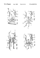
- FIG. 1 illustrates a full side view of a prior art hypodermic needle attached to a hub.
- FIG. 2 is a front view of the hypodermic needle hub shown in FIG. 1 .
- FIG. 3A is a full side view of the hypodermic needle hub shown in FIG. 1 .
- FIG. 3B is a full top view of the hypodermic needle hub shown in FIG. 1 .
- FIG. 4 is a cross sectional view of the hypodermic needle hub shown in FIG. 1 .
- FIG. 5 is a full side view of a hub in accordance with one embodiment of the present invention.
- FIG. 6 is a cross sectional view of the hub shown in FIG. 5 .
- FIG. 7 is a cross sectional view of the hub shown in FIG. 5 having a flange section for retaining a removable cover.
- FIG. 8 is a full side view of the hub shown in FIG. 7 with the addition of a protrusion for engaging a removable cover.
- FIG. 9 is a full rear view of the needle hub shown in FIG. 7 .
- FIG. 10 is a full front view of the hub shown in FIG. 7 .
- FIG. 11 is a full front view of a needle guard assembly in one embodiment of the present invention.
- FIG. 12 is a full front view of the needle guard assembly shown in FIG. 11 .
- FIG. 13 is a full outside view of a needle guard assembly and tether in one embodiment of the present invention.
- FIG. 14 is a full side view of one embodiment of the present invention comprising a unitary construction.
- FIG. 15 illustrates one embodiment of the present invention in a ready-to-use state.
- FIGS. 16-18 illustrate the needle guard assembly being activated to cover the tip of a hypodermic needle.
- FIGS. 19-22 illustrate other embodiments of the present invention.
- FIG. 23 illustrates another embodiment of the present invention.
- FIGS. 24 and 25 show the present invention attached to a blood collection device.
- FIG. 26 shows the present invention included in a catheter device.
- FIG. 27 shows the present invention unitarily attached to a syringe.
- FIGS. 28 and 29 show a needle guard in accordance with one embodiment of the present invention.
- FIG. 30 shows a needle trap that is biased against or towards the hypodermic needle.
- FIG. 31 shows a needle entrapped within a needle guard assembly in one embodiment of the present invention.
- FIG. 32 illustrates a tether in one embodiment of the present invention.
- FIG. 33 illustrates a needle trap in one embodiment of the present invention.
- FIG. 34 is a full open view of a needle guard assembly in one embodiment of the present invention.
- FIG. 35 is a exploded view of one embodiment of the present invention.
- FIG. 36 is an isometric open view of the needle guard shown in FIG. 34 .
- FIG. 37A shows the needle tip guard assembly of FIG. 35 in a ready to use state.
- FIG. 37B shows the needle tip guard assembly of FIG. 37A after it has been activated.
- FIGS. 38A and 38B show a needle tip protective device attached to a fillable syringe in a ready-to-use and shielded position, respectively.
- FIGS. 39A and 39B show a needle tip protective device attached to a prefilled syringe in a ready-to-use and shielded position, respectively.
- FIGS. 40A and 40B show a needle protective device attached to a prefilled cartridge.
- FIG. 41A and 41B show a needle protective device attached to a blood collection apparatus in a ready to use and shielded position, respectively.
- FIGS. 42A and 42B illustrate another embodiment of the present invention.
- FIG. 42C illustrates a needle guard assembly in one embodiment of the present invention.
- FIGS. 43A and 43B show separate embodiments of the needle guard assembly of the present invention.
- FIG. 44A illustrates another embodiment of the present invention.
- FIG. 44B illustrates an enlarged cross-section view of the needle guard shown in FIG. 44 A.
- FIGS. 45A-C, 46 and 47 illustrate a needle hub in one embodiment of the present invention.
- FIGS. 48A-C illustrate several retrofit hub configurations in accordance with the present invention.
- FIG. 49A shows a full side view of the present invention attached to a prior art needle hub.
- FIG. 49B is a cross-sectional view of FIG. 49 A.
- FIG. 50 is cross-sectional side view of the present invention attached to a prefilled syringe.
- FIG. 51 is cross-sectional side view of the present invention attached to a prefilled cartridge syringe hub.
- FIG. 52 is a cross-sectional side view of the present inventions intergrally molded to a prefilled cartridge syringe hub.
- FIG. 53 is cross sectional side view of a prior art I.V. catheter adapter.
- FIG. 54 shows the present invention retrofitted to an I.V. catheter adapter.
- FIG. 55 shows the present invention integrally molded to an I.V. catheter adapter.
- FIG. 56 illustrates the present invention attachable to a blood collection device.
- FIG. 57 illustrates a full front view of a needle guard assembly in one embodiment of the present invention.
- FIG. 58 is a cross sectional side view of a prior art prefilled syringe cartridge hub.
- FIG. 59 is a cross sectional side view of the present invention being threadedly attached to a glass cartridge hub.
- FIG. 60 is a cross sectional side view of the present invention fixedly attached to a glass cartridge.
- FIGS. 61-63 illustrate a catheter in accordance with one embodiment of the present invention.
- FIGS. 64-67 illustrate another embodiment of the present invention.
- FIG. 68 illustrates a full side view of another embodiment of the present invention.
- FIGS. 69-77 illustrate a needle guard assembly in accordance with one embodiment of the present invention.
- FIG. 78 is a cross sectional side view of the present invention for use on a male luer syringe in a ready-to-use state.
- FIG. 79 is a cross sectional side view of the present invention for use on a prefilled syringe or a prefilled cartridge syringe in a ready-for-use state.
- FIG. 80 is cross sectional side view of the hub and cover shown in FIG. 78 .
- FIG. 81 is a cross sectional view of the needle and cover shown in FIG. 79 .
- FIGS. 82 and 83 illustrate a collar for use in one embodiment of the present invention.
- FIG. 84 illustrates another embodiment of the present invention.
- FIG. 85 illustrates yet another embodiment of the present invention.
- FIG. 86 is a graph depicting the interaction of a resilient member and a sliding member without a needle guard notch.
- FIG. 87 is graph depicting the interaction of resilient member and a sliding member with a needle guard notch.
- FIGS. 88-94 illustrate a number of different embodiments of the present invention.
- FIGS. 95 and 96 illustrates a full side view of a needle hub in one embodiment of the present invention.
- FIGS. 97-102 show the embodiments of FIGS. 50, 51 , 52 , 54 and 55 with a needle having a change in contour.
- FIGS. 103-105 illustrate a catheter in yet another embodiment of the present invention.
- FIGS. 106-108 show a cross sectional view of another embodiment of the present invention.
- FIGS. 109-113 illustrate a side-loadable needle guard in one embodiment of the present invention.
- FIGS. 114 and 115 show a needle guard assembly for use in a catheter.
- FIGS. 116 and 119 show a needle trap in one embodiment of the present invention.
- FIG. 117 is a full top view of a housing in one embodiment of the present invention.
- FIG. 118 illustrates a cross sectional and cut-away view of a catheter introducer in one embodiment of the present invention.
- FIGS. 120 and 121 illustrate catheter assemblies in yet other embodiments of the present invention.
- FIGS. 122A-122C show an isometric view of a catheter in one embodiment of the present invention.
- FIGS. 123 and 124 show a needle trap assembly for use in a catheter.
- FIGS. 125-130 illustrate a needle guard in yet another embodiment of the present invention.
- a needle tip protective device is described.
- numerous specific details are set forth in order to provide a thorough understanding of the present invention.
- the invention may be practiced without these specific details.
- well-known structures and processing steps have not been shown in particular detail in order to avoid unnecessarily obscuring the present invention.
- hypodermic needle devices such as fillable syringes, prefilled syringes, prefilled cartridge syringes, blood collection devices and catheters. It is appreciated, however, that the present invention is not limited to these devices, and may be used in any application where it is desirable to provide a protective covering at the tip of a needle or other elongated object.
- the needle covering invention disclosed herein in regard to an I.V. catheter can easily be adapted to all types of other catheters where a needle may be used, including, but not limited to, neurological, urological, central venous, oximetry, thermodilution, PTCA, PTA, angiography, atherectomy, enlectrophysiology, suction and wound drainage, cardiovascular, pulmonary and spinal catheters.
- the needle covering invention described herein on a syringe can also be easily adapted to a blood collection needle, or any other needles used in invasive procedures, including, but not limited to, angiography, cardiovascular, ophthalmological, orthopedic, dentistry, veterinary, chemotherapy and arterial blood gas.
- FIG. 1 is a full side view drawing of a prior art standard, exposed hypodermic needle 10 , having a sharpened needle tip 11 at the distal end with the opposite, or proximal end of the needle 10 attached to a hub 12 , with at least one flange 1 at the very proximal end for attaching the needle hub 12 to a male luer fitting, a needle nest 4 at the distal end of the needle hub 12 , for fixedly attaching the needle 10 , and a plurality of fins 2 on the needle nest 4 .
- FIG. 2 is a full front view drawing of the prior art hypodermic needle hub 12 with an aperture creating a fluid/gaseous path to the hypodermic needle, a needle nest 4 for fixedly attaching the hypodermic needle 10 therein, with the needle nest 4 surrounded by a plurality of fins 2 and a plurality of flanges 1 .
- FIG. 3A is a full side view drawing of the prior art hypodermic needle hub 12 with at least one flange 1 for attaching the needle hub 12 to a male luer fitting, a needle nest 4 for fixedly attaching the needle (not shown here) and a plurality of fins 2 .
- FIG. 3B is a full top view drawing of the prior art hypodermic needle hub 12 with at least one flange 1 for attaching the needle hub 12 to a male luer fitting, a needle nest 4 for fixedly attaching the needle (not shown here) and a plurality of fins 2 .
- FIG. 4 is a cross-sectional view of the prior art hypodermic needle hub shown in FIG. 2 along axis 4 — 4 comprising a hub portion 12 with a flange 1 , an aperture creating a fluid/gaseous path to the hypodermic needle (not shown here), a needle nest 4 for fixedly attaching a hypodermic needle (not shown here), and a plurality of fins 2 .
- FIG. 5 is a full side view drawing of the hub section of the disclosed invention comprising a hypodermic needle hub 112 with at least one flange 101 for attaching the needle hub 112 to a male luer fitting, a needle nest 104 (not shown here) for fixedly attaching the needle (not shown in this view), an inner aperture creating a fluid/gaseous path between the needle hub 112 and the needle (not shown here), a protrusion 5 .
- the protrusion being connected to the extended sidewall section 15 at the distal end of the needle hub 112 , and a moveable latching arm 26 with a finger pad 27 attached to the needle hub 112 by a hinge section 23 , with the moveable latching arm 26 having a protrusion 21 for retaining a component in a releasable position on the needle hub 112 , said moveable latching arm 26 shown in the preferred molded position.
- FIG. 6 is a cross-sectional side view of FIG. 5 .
- Needle hub 112 includes an inner aperture that provides a fluid/gaseous. path between the needle hub 112 and the needle (not shown here).
- Arrow “M” indicates the directional movement of latch 26 .
- FIG. 7 is a cross-sectional side view of FIG. 5 having a section 16 for removably holding a removable cover over the hypodermic needle.
- FIG. 8 is a full side view of the hub 112 shown in FIG. 7, with the addition of at least one protrusion 14 located adjacent to section 16 , said protrusion 14 being engagable with a removable cover.
- Protrusion 14 in conjunction with a contacting member of removable cover, is positioned to facilitate attachment or removal of a hypodermic needle from a connecting device.
- Hub 112 also includes a protrusion or cleat 17 with a cap or holding means 18 to attach a tether.
- FIG. 9 is a full rear view of needle hub 112 shown in FIG. 7 .
- FIG. 10 is a full front view drawing of the disclosed hub invention comprising a hypodermic needle hub 112 with an extended wall section 15 , an aperture creating a fluid/gaseous path to the hypodermic needle (not shown), a needle nest 104 for fixedly attaching the needle (not shown), a protrusion 5 which can be used as a guide for aligning another component, a section 16 for removably holding a removable cover over the hypodermic needle (not shown here), a protrusion 14 located adjacent to section 16 for engaging a corresponding component of a removable cover (not shown), and a moveable latching arm 26 with a finger pad 27 attached to the needle hub 112 by a hinge section 23 (not shown).
- FIG. 11 is a full front view of a needle guard assembly 22 positioned on the front of the hub 112 comprising a guide aperture 47 with a hypodermic needle 10 therethrough, said aperture 47 being created by coupling the open-faced sections of the needle guard assembly 22 together at a split line 43 , a protrusion 5 which is used as a guide for aligning the needle guard assembly 22 on the hub 112 whereby an aperture is created on the needle guard assembly 22 when the open-faced sections of the needle guard assembly 22 are coupled together, a section 16 for removably holding a removable cover over the hypodermic needle 10 , a protrusion 14 located adjacent to section 16 for engaging a corresponding component of a removable cover (not shown).
- needle guard 22 also includes a moveable latching arm that is attached to needle hub 112 by a hinge section.
- a tether (not shown) is generally used to fixedly attach needle guard 22 to hub 112 .
- FIG. 12 is a full front view of the needle guard assembly 22 shown in FIG. 11 comprising a guide aperture 47 created by coupling the open-faced sections of the needle guard assembly 22 together at the split line 43 , a recess 25 with a protrusion 44 at the rear or inner end of the recess 25 , a tether 24 connected to a hinge section 28 and an aperture adjacent to the hinge section.
- FIG. 13 is a full outside, top view of the needle guard assembly 22 and tether 24 as manufactured comprising an open-faced needle guard 22 with a hinge section 28 , with adjacent lands 39 which create an aperture when the needle guard assembly 22 is coupled together, a needle tip guard 41 with a hinge section 40 allowing the needle tip guard 41 to move, a recess 25 with a protrusion 44 and a tether 24 with a connector or loop 20 .
- FIG. 14 is a full side view of a unitary, one piece embodiment of the invention comprising a hypodermic needle hub 112 , having at least one flange 101 , an extended wall section 15 , a protrusion 5 , a moveable latching arm 26 connected to said hub 112 by a hinge 23 , said latching arm having a finger pad 27 at the proximal end and a hooking protrusion 21 at the distal end, a protrusion 17 connecting a tether 24 to a slidable needle guard assembly 22 , with a moveable needle tip guard 41 and a hinge section 40 .
- protrusion 5 may also serve as an aspiration stop when a needle is inserted into a medicine vial.
- FIG. 15 is a full side view of the invention shown in the ready to use configuration comprising a hypodermic needle 10 with a sharpened tip 11 , a needle hub 112 , with at least one flange 101 , an extended sidewall section 15 , a section 16 for removably attaching a cover, a protrusion 14 located adjacent to section 16 , said protrusion 14 being engagable with a removable cover, said protrusion 14 in conjunction with corresponding member of removable cover, being positioned to facilitate attachment or removal of a hypodermic needle from a connecting device, a moveable latching arm 26 connected to hub 112 by a hinge 23 , said latching arm having a finger pad 27 at the proximal end and a hooking protrusion 21 at the distal end, said latching arm 26 releasably holding said needle guard 22 and a compressed resilient member 19 in a retained position, said needle guard 22 having a moveable needle tip guard 41 which is biasly contacting the hypodermic needle, a protru
- FIG. 16 is a full side view FIG. 15 with a compressive longitudinal force being exerted on the needle guard assembly 22 , whereby the needle guard assembly 22 and compressed resilient member 19 move enough to release the hold by the protrusion 21 of the moveable latching arm 26 .
- FIG. 17 is a full side view FIG. 15 with the released needle guard assembly 22 being urged to the distal end of the hypodermic needle 10 by the extending force of the resilient member 19 , said needle tip guard 41 is biasly contacting said hypodermic needle 10 by the inherent memory of the molded configuration of said needle tip guard 41 and/or the extending force of the surrounding resilient member 19 .
- FIG. 18 is a full side view FIG. 15 with the resilient member 19 extended and still exerting force on the needle guard assembly 22 , said resilient member 19 assists inherently molded bias of needle tip guard 41 by urging said needle tip guard 41 inwardly and ahead of the sharpened needle tip, said needle guard assembly 22 is limited from advancing further by the extended tether 24 , with the sharpened hypodermic needle tip being entrapped within the needle guard assembly 22 , with the needle tip guard 41 now securely positioned ahead of the sharpened needle tip said needle tip guard 41 blocking the aperture guide of the needle guard assembly 22 , ensuring safe containment of the sharpened tip.
- FIG. 19 is a full bottom view of FIG. 15 showing the elements of the invention and a rectangular finger pad configuration, although the finger pad configuration only needs to be suitable (round, square, triangular or the like) to facilitate a manual force to release the hold on retained needle guard assembly 22 , said needle guard assembly 22 having a recess 25 for engaging the distal end of the movable latching arm 26 to the corresponding section on the needle guard assembly 22 .
- FIG. 20 is a full top view of FIG. 15 showing the elements of the invention and having a tether 24 which can have a round, square, elliptical or ribbon-like cross section and hinge section 28 .
- the tether can comprise either rigid or flexible characteristics, and can be unitary molded with other components, or be a separate component.
- a rigid tether would have to be able to slide along the side of a syringe, prefilled syringe or cartridge, blood collection needle holder or I.V. catheter when the device is used, and said tether could slide through an aperture which would limit the axial forward movement of the tether and needle guard.
- This rigid tether would have to have a proximal end larger than the aperture, so the tether would be limited in its slidable movement.
- a flexible tether can be made more resilient or rigid by changing the molecular alignment of the molecules of the tether component by stretching, heating, radiation processing or the like.
- the tether can be manufactured separately, or connected to either the hub component, the needle guard assembly or the needle guard housing.
- the tether could be comprised from a single variety, or a combination of materials including, but not limited to: plastic resin, synthetic material, organic material, cloth, woven material, stranded material, metal, silk, or a composite material.
- FIG. 21 is a full side view of FIG. 15 having an extended protrusion 105 for preventing premature release of the releasable needle guard assembly 22 .
- This embodiment can be used for blood collection purposes, indwelling catheter placement or preventing premature activation during medicine aspiration.
- FIG. 22 is a full top view of FIG. 15 having an extended protrusion 105 for preventing premature release of the releasable needle guard assembly 22 .
- FIG. 23 is a cross-sectional view of the invention ready for use having the elements described herein, with the resilient member 19 in a compressed position with the needle guard assembly releasably held by the protrusion 21 of the moveable latching arm 26 , an aperture for orienting said needle guard assembly 22 adjacent to said hub portion 112 , and an aperture 47 with a hypodermic needle 10 therethrough, said latching arm 26 having a protrusion 49 for engaging said needle guard assembly 22 when said needle guard assembly is moved toward said hub portion 112 , said protrusion 49 manually moves said latching arm 26 in an outward manner ensuring said latching arm 26 moves outwardly releasing the hold on the needle guard assembly 22 .
- FIG. 24 is a full side view of the invention for blood collecting purposes showing the elements described and notated in the previous drawings in addition to a double-lancet hypodermic needle 10 having a sharpened tip 11 at the distal end and a sharpened tip 111 at the proximal end (see FIG. 25 ), a hub 212 having a threaded section for removably attaching the hub into a needle holder 45 (see FIG. 25) by means of threads 74 , and a piercable, collapsible cover 48 on the distal end of the needle 110 and a protrusion 105 .
- FIG. 25 is a full side view of the invention for blood collecting purposes showing the elements described and notated in the previous drawings in addition to the invention being removably attached to a needle holder 45 , said needle holder 45 having a larger opening at the proximal end for inserting a removable blood collection tube, and a smaller opening at the distal end for removably attaching a blood collection needle 110 and hub 212 .
- a manual releasing means is activated by pressing the finger pad 27 in a downward or inward manner, this is indicated by the arrow “F” pointing toward the finger pad 27 .
- attachment means of connecting the invention to a blood collection needle holder 45 is not limited to the threaded means 74 shown throughout this application.
- Other attachment means such as frictional engagement, snap fit, wedging or the like may also be used to accomplish the same function.
- FIG. 26 is a full side view of the invention with a removable, indwelling catheter, having a hub 312 attached to a hollow bore needle 210 with a distal stylet 211 and a removable, indwelling catheter 51 and catheter hub 50 slidably disposed on said needle 210 . All other elements notated are described in the previous drawings.
- FIG. 27 is a full side view of the invention in a ready to use state unitarily attached to a syringe 6 by the hub 112 . All other elements notated are described in the previous drawings.
- FIG. 28 is a full front view of the needle guard assembly shown in an open-faced configuration comprising a needle guard assembly 22 having a hinge section 28 joining each section, a split line 43 where the sections mate together, an aperture guide 47 on each section, a recess 25 on one section having a protrusion 44 for joining with the corresponding element 144 on the other section of said needle guard assembly 22 , a moveable needle tip guard 41 and a post 36 for joining the needle guard assembly 22 sections together.
- FIG. 29 is a full rear view of the needle guard assembly shown in an open-faced configuration comprising a needle guard assembly 22 having a hinge section 28 joining each section, a split line 43 where the sections mate together, an aperture guide 47 on each section, a protrusion 44 for joining with the corresponding element 144 on the other needle guard assembly 22 section, a moveable needle tip guard 41 , at least one post or protrusion 36 on one needle guard assembly 22 section which enters at least one corresponding slot 37 on the other needle guard assembly 22 section for securing the sections together.
- FIG. 30 is a cross-sectional side view showing the interaction of the needle guard assembly 22 with the resilient member 19 and hypodermic needle 10 and sharpened needle tip 11 , comprising a moveable needle guard assembly 22 with a hypodermic needle 10 therethrough, with resilient member 19 urging the needle guard assembly 22 toward the distal end of the hypodermic needle 10 .
- the needle guard assembly 22 having a moveable needle tip guard 41 with a hinge section 40 , said needle tip guard 41 is molded in a manner whereby the needle tip guard 41 comprises an inherent biasing force toward the hypodermic needle 10 , another biasing force is exerted on the needle tip guard 41 by, the extending force of the resilient member 19 , said needle tip guard 41 enters the corresponding recess 31 when said needle tip guard 41 advances beyond the sharpened needle tip 11 , said needle tip guard 41 slidably contacts said hypodermic needle 10 .
- the needle guard 22 is attached to a hub element 12 by means of a tether 24 as described and notated in the previous drawings.
- FIG. 31 is cross-sectional side view showing containment of the sharpened needle tip 11 within the needle guard assembly 22 comprising a needle guard assembly 22 with a hypodermic needle 10 therethrough, said needle guard assembly 22 being urged beyond the distal end of the hypodermic needle 10 and sharpened needle tip 11 by the extending force of a resilient member 19 whereby the moveable, self-biasing needle tip guard 41 of the needle guard assembly 22 moves in front of the sharpened needle tip 11 , containing the sharpened needle tip 11 within the needle guard assembly 22 and behind the substantially impenetrable needle tip guard 41 having a hinge section 40 .
- the extending force of the resilient member 19 urges the needle tip guard 41 inwardly to a covering position, said resilient member 19 surrounds both the needle guard assembly 22 and the outer wall of the needle tip guard 41 holding the needle tip guard 41 in a closed, protective position by a radially confining force.
- the needle tip guard 41 enters the corresponding recess 31 of the needle guard assembly 22 , preventing movement and ensuring safe containment of the sharpened needle tip 11 within the needle guard assembly 22 .
- the needle guard 22 is attached to a hub or housing by means of a tether as described and notated in the previous drawings.
- FIG. 32 is a full top view of a separate tether 24 with connecting loops 20 at the proximal and distal ends. This tether embodiment is used with a separate hub component and separate needle guard assembly component.
- FIG. 33 is a cross sectional side view of the needle guard assembly 22 comprising a needle tip guard 41 having a hinge section 40 connected to the needle guard assembly 22 .
- Said needle tip guard 41 is molded in a self-biasing manner as shown and is moveable to an open and closed position.
- Said needle tip guard may comprise a substantially impenetrable plastic resin and/or a substantially impenetrable metal.
- FIG. 34 is a full open view of the interior of the open-face needle guard assembly 22 as manufactured and before being joined together.
- Said needle guard assembly 22 comprising two joining sections which are connected by a hinge section 28 having a tether 24 , one needle guard assembly section having a moveable, self-biasing, substantially impenetrable needle tip guard 41 with a moveable hinge 40 connected to said needle guard assembly 22 , a post or protrusion 36 , a recess 25 with a protrusion 44 and a recess 38 for nesting said needle guard assembly 22 adjacent to the needle hub 112 , 212 or 312 as shown in the previous drawings; with the corresponding needle guard assembly section having a corresponding slot 31 for said needle tip guard 41 to enter, a slot 37 for receiving the corresponding post 36 , a proximal inner guide section 35 and a distal inner guide section 47 for the hypodermic needle 10 (not shown), a corresponding receiving section 144 for recess 25 and protrusion 44 , and a reces
- FIG. 35 is a full, exploded view of the invention having the elements described herein the other accompanying drawings comprising a slidable needle guard assembly 22 in the closed face configuration having a tether 24 and loop 20 ; a resilient member 19 ; and a hypodermic needle 10 fixedly attached the needle hub.
- FIG. 36 shows needle guard assembly 22 in a full view, open-faced configuration. The open face, or “clam-shell” configuration of the needle guard make this embodiment feasible using standard injection molding techniques.
- the sharpened needle 10 is first attached to the hub portion 112 , then the needle 10 is coated with a friction-reducing lubricant, the resilient member 19 is concentrically disposed over the needle 10 and compressed, then the needle guard assembly 22 is assembled from the side of the needle 10 keeping the sharpened tip 11 from being contacted, the needle guard assembly 22 and tether 24 are then attached to the hub 122 by a connecting means 20 .
- the extended wall section 15 can be eliminated for the invention to work, but shields the resilient member 19 .
- the elements of the needle guard assembly 22 , in relation to each other, and in relation to the bevel of the sharpened needle tip 11 , can also be oriented as may be deemed necessary to suit a specific procedure or purpose.
- FIG. 37A is an isometric drawing of a needle tip protective device 500 in one embodiment of the invention.
- FIG. 37A shows protective device 500 in a ready-to use position.
- FIG. 37B shows the protective device 500 shielding the needle tip within the needle guard assembly 22 .
- FIG. 38A and 38B show a needle tip protective device 500 in one embodiment of the invention attached to a fillable syringe 501 in a ready-to-use position and a shielded position, respectively.
- FIG. 39A and 39B show a needle tip protective device 500 in one embodiment of the present invention attached to a prefilled syringe 502 in a ready-to-use position and a shielded position, respectively.
- FIG. 40A and 40B show a needle protective device 500 in one embodiment of the invention attached to a prefilled cartridge 503 .
- FIG. 40A shows the prefilled cartridge 503 before use.
- FIG. 40B shows the prefilled cartridge 503 after the protective device 500 is activated.
- FIG. 41A and 41B shows a needle protective device 500 in one embodiment of the invention attached to a blood collection device 504 in a ready-to-use position and a shielded position, respectively.
- FIG. 42A illustrates a needle tip guard assembly in yet another embodiment of the present invention for protecting the distal tip 11 of a standard hypodermic needle 10 .
- the assembly includes a needle guard 22 that is slidably mounted on needle 10 .
- Needle guard 22 contains a movable needle trap 41 that is biased against or toward the shaft of needle 10 .
- Needle trap 41 advances over the tip 11 of the needle 10 , entrapping the needle tip 11 , when needle guard 22 is positioned near the distal tip of needle 10 .
- FIG. 42B shows distal needle tip 11 captured within needle guard 22 .
- needle guard 22 is moved forward along the shaft of needle 10 by the user.
- FIG. 42A needle guard 22 is moved forward along the shaft of needle 10 by the user.
- needle trap 41 is shown as a detachable element of needle guard 22 that is insertable into a slot 80 located adjacent the proximal end of needle guard 22 .
- Needle trap 41 generally comprises a flexible metal member. Other impregnable materials that are not susceptible to fatigue may also be used. For example, some plastics or other resin based materials may be used. In such instances, needle trap 41 may be integrally molded with needle guard 22 . A recess 31 may be included within needle guard 22 for receiving needle trap 41 .
- a flexible tether 24 limits the forward movement of the needle guard 22 along the needle 10 . Other limiting means, such as, for example, a change in contour in needle 10 or the use of a rigid tether assembly may be used in lieu of the flexible tether. These limiting devices will be described in greater detail later in this description.
- FIG. 42C shows needle guard 22 a that is another embodiment of the needle guard 22 shown in FIGS. 42A and 42B.
- the needle guard 22 a of FIG. 42C includes an integrally molded needle trap 41 a , a notch 61 a , a recess 61 b in trap 41 a , and needle guard 22 , respectively.
- a resilient member 102 is held within notch 61 a and recess 61 b .
- the stored energy of resilient member 102 urges needle trap 41 a toward or against needle 10 .
- Resilient member 102 may comprise a “v” shape or may simply comprise a member that has been curved to create a stored energy.
- FIG. 43A is a full side view one embodiment of the present invention with the resilient member 119 extended and still exerting force on the needle guard assembly 22 , said resilient member 119 assists inherently molded bias of needle guard trap 41 by urging said needle guard trap 41 inwardly and in front of the sharpened needle tip 11 (see FIG. 33 ), said needle guard assembly 22 is limited from advancing further by the limiting tether 24 , with the sharpened hypodermic needle tip being entrapped within the needle guard assembly 22 , with the needle guard trap 41 now securely positioned in front of the sharpened needle tip 11 said needle guard trap 41 blocking the aperture guide opening 47 of the needle guard assembly 22 , ensuring safe containment of said sharpened tip 11 within the needle guard assembly 22 .
- the needle guard trap 41 is attached to the needle guard assembly 22 by a hinge section 40 .
- a hollow bore hypodermic needle 10 is fixedly attached to a hub 112 , said hub 112 having at least one proximal flange 101 for attaching said hub 112 to a male luer fitting, said hub 112 also having a flange 16 for removably attaching a protective storage cover (not shown), said flange 16 having at least one shoulder or projection 14 for interfacing with a corresponding portion of a storage cover to allow twisted attachment and/or removal of said hub 112 to or from a medical device, said hub also having a body portion 15 , a protrusion 5 , and a movable latching arm 26 , said latching arm 26 being fixedly attached to said hub body 15 by a hinge section 23 , said latching arm also having a hook 21 , a protrusion, cam, or ramp 49 and a finger pad or button 27 .
- FIG. 43B shows the protective needle guard assembly of FIG. 43A attached to a syringe 6 .
- the protective needle guard assembly may be integral to syringe 6 , or may be attached as an add-on component.
- FIG. 44A is a full side view of the disclosed invention with the resilient member 119 extended and still exerting an extending force on the needle guard assembly 22 , said resilient member 119 assists inherently molded bias of needle guard trap 41 by urging said needle guard trap 41 inwardly and in front of the sharpened needle tip 11 said needle guard assembly 22 is limited from advancing further by the limiting tether 24 , with the sharpened hypodermic needle tip 11 being trapped within the needle guard assembly 22 , with the needle guard trap 41 now securely positioned in front of the sharpened needle tip 11 .
- Said needle guard 22 having an extended slot section 44 a for releasably holding said needle guard assembly 22 in a retained position.
- Said extended slot section 44 a places the interface between the latching arm hook 21 and the needle guard assembly 22 away from any potential binding which may occur during needle insertion. If the retaining means interface is too close to the insertion surface, the latching arm 26 may be prevented from releasably holding the needle guard assembly 22 .
- a flexible projection 107 is included within the needle guard assembly for retaining the end coil of spring 119 in a locked position after the needle tip protection device has been activated.
- FIG. 44B illustrates a cross-sectional view of flexible projection 107 .
- the needle guard trap 41 is attached to the needle guard assembly 22 at a hinge section 40 .
- the needle 10 is fixedly attached to a hub 112 , said hub 112 having at least one proximal flange 101 for attaching said hub 112 to a male luer fitting, said hub also having a body portion 15 , a protrusion 5 , and a movable latching arm 26 , said latching arm 26 being fixedly attached to said hub body 15 by a hinge section 23 , said latching arm also having a hook 21 and protrusion 49 .
- FIG. 45A is a full side view drawing of the needle hub. 412 , in accordance with one embodiment of the invention comprising a hypodermic needle hub 412 with a flange 401 for attaching the needle hub 412 to a male luer fitting, a needle nest 404 for fixedly attaching the needle, a plurality of fins 402 , and a land 75 for attaching another component to the hub 412 .
- FIG. 45B is a full top view of the needle hub 412 shown in FIG. 45B having a flange 401 for attaching the needle hub 412 to a male luer fitting, a needle nest 404 for fixedly attaching a needle, a plurality of fins 402 , and a land 75 for attaching another component to the hub 412 .
- FIG. 45C is a cross sectional side view of FIG. 45A comprising a hypodermic needle hub 412 with a flange 401 for attaching the needle hub 412 to a male luer fitting a needle nest 404 for fixedly attaching the needle 10 , an aperture therethrough creating a fluid/gaseous path from the said hub 412 to said needle plurality of fins 402 , and a land 75 for attaching another component to the hub 412 .
- FIG. 46 is a full side view drawing of the disclosed invention comprising a hypodermic needle hub 412 with a flange 401 for attaching the needle hub 412 to a male luer fitting, a needle nest 404 for fixedly attaching the needle, at least one, or a plurality of shortened fins 403 , and a land 75 for, attaching another component to the hub 412 .
- FIG. 47 is a full front view drawing of FIGS. 45A and 46 comprising a hypodermic needle hub 412 with an aperture creating a fluid/gaseous path to the hypodermic needle 10 , a needle nest 404 having adjacent at least one, or a plurality of fins 402 or 403 , at least one, or a plurality of flanges 401 and a land 75 .
- FIG. 48A is a is a full side view of the invention having a retrofitted hub portion 215 being fixedly attached to a hub portion 412 by a heatstake connection.
- Said hub portion 215 having an annular flange 16 for connecting a protective storage cover, a protrusion 17 for attaching a tether, said protrusion 17 having an aperture for insertably attaching or bonding the tether, said protrusion 17 having an angled proximal end to eliminate any possibility of the tether catching on the protrusion 17 when the needle guard 22 is activated.
- a hub portion 215 also includes a well or pocket 18 for removably inserting a tether in an out of the way fashion, and a retaining means 77 for releasably holding said needle guard 22 in a retained position adjacent to said hub portion 215 .
- FIG. 48B is a full front view of the hub 215 described in FIG. 48A comprising a hypodermic needle hub 215 having an aperture with a plurality of slots which correspondingly fits onto the distal end of a hypodermic needle hub shown throughout this application, said slots accept the fin or fins 402 from said hub 412 , an annular flange 16 , a protrusion 17 for attaching a tether or the like, a well or pocket 18 for removably inserting a tether or the like, and a retaining means 77 having an aperture 78 for releasably holding said needle guard 22 in a retained position adjacent to said hub portion 215 .
- FIG. 48C is a full front view of FIG. 48A comprising a hypodermic needle hub portion 215 , an aperture which correspondingly fits onto the distal end of a hypodermic needle hub shown throughout this application, an annular flange 16 .
- FIG. 49A is a full side view of the disclosed invention being fixedly attached to a prior art needle hub 12 having at least one flange 1 for attaching the needle hub 12 to a male luer fitting, a section 16 for removably holding a protective storage cover 54 over the hypodermic needle 10 (shown in other drawings in this application), a protrusion 5 located at the distal end of the hub portion 15 , said protrusion 5 being connected to the hub portion 15 at the distal end of the hub portion 15 , said section 16 having a shoulder 14 for twistedly attaching said invention to said storage cover, and a moveable latching arm 26 with a finger pad 27 , attached to the hub portion 15 by a hinge section 23 , said finger pad 27 having at least one protrusion for creating a more positive grip or contact with said finger pad 27 .
- Finger pad 27 also comprising a different, or bright color, which serves as a visual indicator for the user to easily locate the finger pad for manual release of said needle guard assembly 22 or the like, with the moveable latching arm 26 having a protrusion 21 for retaining a component in a releasable position adjacent to said hub portion 15 , said moveable latching arm 26 shown in the preferred molded position.
- FIG. 49B is a cross-sectional side view of FIG. 49A showing the disclosed invention attached to a prior art needle hub 12 said needle hub 12 comprising a hypodermic at least one flange 1 for attaching the needle hub 12 to a male luer fitting, on one side a needle nest 4 for fixedly attaching the needle (not shown) said needle nest 4 having at least one, or a plurality of fins 2 and an inner aperture creating a fluid/gaseous path between the needle hub 12 and the needle.
- the invention is shown being retrofitted to said prior art hub 12 , said attachment means comprising a spin weld, sonic weld, heat.
- the needle nest 4 having a recess or slot manufactured to accept said protrusion 64 of hub portion 15 , said hub portion 15 having a protrusion 5 located at the distal end of the hub portion 15 , said protrusion 5 being connected at the distal end of the hub portion 15 , said hub portion 15 also having a section 16 for removably attaching a protective storage covers (not shown) said section 16 also having a means for creating a tortuous path preventing contamination from entering the sterile field created by enclosing the needle 10 , needle guard 22 and hub portion 15 within a protective storage cover.
- Hub portion 15 includes a moveable latching arm or lever 26 attached to the hub portion 15 by a hinge section 23 , with the moveable latching arm 26 having finger pad or button 27 , a protrusion 21 for retaining a component in a releasably held position adjacent to the hub portion 15 , said latching arm 26 also having a protrusion 49 for biasing the latching arm 26 in an outward manner when a compressive force is applied to the releasably held needle guard 22 with said, moveable latching arm 26 shown in the preferred position for retaining at least one component in a retained position on the hypodermic needle hub 12 .
- FIG. 50 is a cross-sectional side view of the invention attached to a prior art glass pre-filled syringe 6 having a nest bead 7 and a hypodermic needle 10 showing the disclosed invention attached to said glass pre-filled syringe 6 .
- Hub body 15 is fixedly attached to syringe 6 at the nest bead 7 by the attaching section 65 ; said hub body 15 having a protrusion 5 located at the distal end of said hub portion 15 , said protrusion 5 being connected at the distal end of the hub portion 15 , said hub portion 15 having a fixedly attached tether 24 , said hub body 15 also having a section 16 for removably attaching a protective storage cover a moveable latching arm or lever 26 attached to the hub body 15 by a hinge section 23 , said lever 26 having a touch pad 27 , a protrusion 21 for retaining a component in a releasable position on the hub portion 15 , said latching arm 26 also having a protrusion 49 for urging said latching arm 26 in an outward manner when a compressive force is applied to a releasably held needle guard. with said moveable latching arm 26 shown in the preferred position for retaining at least one component in a retained position on the hub portion 15 .
- FIG. 51 is a cross-sectional side view of the invention attached to a prior art pre-filled cartridge syringe hub 8 a having a fixedly attached needle 10 with a sharpened proximal end 111 and a sharpened distal end, said sharpened proximal end 111 for piercing the stopper of a medicine or fluid cartridge.
- Hub portion 15 is fixedly attached to said syringe hub 8 a at the needle nest 4 said hub portion 15 having a protrusion 5 located on said hub portion 15 , said protrusion 5 having an attachment section 17 with an aperture for inserting a tether (not shown), said attachment section 17 having an chamfered face on the proximal side to eliminate any possibility of the tether catching and hanging up on said attachment section 17 when said needle guard is released from a retained position, said hub portion 15 also having a section 16 for removably attaching a protective storage cover and a moveable latching arm or lever 26 with a touch pad 27 attached to the hub portion 15 by a hinge section 23 , with the moveable latching arm 26 having a protrusion 21 for retaining a component in a releasably held position on the hub portion 15 , said latching arm 26 also having a protrusion 49 for urging the latching arm 26 in an outward manner when a compressive force is applied to a releasably held needle guard
- FIG. 52 is a cross-sectional side view of the invention integrally molded to a pre-filled cartridge syringe hub 8 b having a fixedly attached needle 10 with a sharpened proximal end 111 and a sharpened distal end (not shown) said sharpened proximal end 111 is for piercing the stopper of a medicine or fluid cartridge.
- Integral hub portion 15 having a needle nest 4 , protrusion 5 located on said hub portion 15 , said protrusion 5 having an attachment section 17 with an slot for inserting a tether (not shown) said attachment section 17 having an chamfered face on the proximal side to eliminate any possibility of the tether 24 catching and hanging up on said attachment section 17 , said hub portion 15 also having a section 16 for removably attaching a protective storage cover, a moveable latching arm or lever 26 attached to the hub portion 15 by a hinge section 23 , with the moveable latching arm 26 having a protrusion 21 for retaining a component in a releasable position adjacent to the hub portion 15 , said latching arm 26 also having a protrusion 49 for urging the latching arm 26 in an outward manner when a compressive force is applied to a releasably held needle guard 22 (shown in other drawings in this application), with said moveable latching arm 26 shown in the preferred position for retaining at least one component in
- FIG. 53 is a cross-sectional side view drawing of a prior art indwelling intravenous (I.V.) catheter 29 having a catheter mounting section 9 with a section 18 for removably attaching a protective storage cover, a fixedly attached hypodermic needle 10 , and a male section 78 for removably attaching an indwelling I.V. catheter hub 13 .
- I.V. intravenous
- FIG. 54 is a cross-sectional side view an I.V. catheter having a mounting section 9 , a section 18 for removably attaching a protective storage cover a hypodermic needle 10 being fixedly attached to a needle nest 4 ; said catheter mounting section 9 being retrofitted with the present invention.
- the invention comprises a hub portion 15 being fixedly attached to said catheter mounting section 9 at the nest 4 by the attaching section 66 , said hub portion 15 having a protrusion 5 located at the distal end of said hub portion 15 , said protrusion 5 being connected to the hub portion 15 , said hub portion 15 having a fixedly attached tether 24 , said hub portion 15 also having a section 16 for removably attaching a protective storage cover, a moveable latching arm or lever 26 attached to the hub portion 15 by a hinge section 23 , with the moveable latching arm 26 having a protrusion 21 for retaining a component in a releasable position on the hub portion 15 , said latching arm 26 also having a protrusion 49 for urging the latching arm 26 in an outward manner when a compressive force is applied to the releasably held needle guard (not shown), with said moveable latching arm 26 shown in the preferred position for retaining at least one component in a retained position on the hub portion 15 .
- FIG. 55 is a cross-sectional side view of the present invention integrally molded to an I.V. catheter mounting section. 9 .
- FIG. 56 illustrates a hub portion 15 of the present invention that may be attached to a blood collection device similar to that showing FIG. 25 .
- FIG. 57 is a full front view of the needle guard assembly 22 of FIG. 11 further comprising at least one fin 63 protecting the movement of said latching arm 26 , allowing said latching arm 26 to freely disengage when the needle guard 22 is moved towards the hub 12 when said needle guard 22 contacts the protrusion 49 .
- FIG. 58 is a cross-sectional side view of a prior art pre-filled syringe cartridge comprising a glass cartridge 6 , a glass cartridge hub 68 having a needle nest 4 for fixedly attaching a needle 10 , said needle 10 having a sharpened distal end 11 said hub 68 also having a threaded section 67 .
- FIG. 59 is a cross sectional side view of the invention being threadedly attached to a glass cartridge hub 68 , said glass cartridge hub 68 being fixedly attached to a glass cartridge 6 , said hub 68 having a needle nest 4 for fixedly attaching a needle 10 , said needle 10 having a sharpened distal end (not shown) said hub 68 also having a threaded section 67 .
- Hub body 15 is fixedly attached to said glass cartridge hub 68 by the threaded section 67 , said hub 15 having a protrusion 5 located at the distal end of said hub portion 15 , said protrusion 5 being connected at the distal end of the hub portion 15 , said hub portion 15 having a fixedly attached tether 24 .
- Hub body 15 also includes a section 16 for removably attaching a protective storage cover (FIGS. 78 and 79 ), a moveable latching arm or lever 26 with a touch pad 27 attached to the hub body 15 by a hinge. section 23 , with the moveable latching arm 26 having a protrusion 21 for retaining a component in a releasable position on the hub portion 15 , said latching arm 26 also having a protrusion 49 for urging said latching arm 26 in an outward manner when a compressive force is applied to a releasably held needle guard with said moveable latching arm 26 shown in the preferred position for retaining at least one component in a retained position on the hub body 15 .
- FIG. 60 is a cross sectional side view of the invention being fixedly attached to a glass cartridge 6 , comprising a hub 69 having a needle nest 4 for fixedly attaching a needle 10 , a hub portion 15 being integrally molded to said hub 69 ; said hub portion 15 having a protrusion 5 located at the distal end of said hub portion 15 , said protrusion 5 being connected at the distal end of the hub portion 15 , said hub portion 15 having a fixedly attached tether 24 , said tether 24 could also be fixedly attached to section 16 , said hub 69 also having a section 16 for removably attaching a protective storage cover, a moveable latching arm or lever 26 attached to the hub portion 15 by a hinge section 23 , with the moveable latching arm 26 having a protrusion 21 for retaining a component in a releasable position on the hub portion 15 , said latching arm 26 also having a protrusion 49 for urging said latching arm 26 in an outward manner when
- FIG. 61 is a cross sectional top view of the invention shown on an indwelling catheter 29 embodiment, having a movable needle guard 22 a and a separable indwelling I.V. catheter 29 , said catheter 29 being fixedly attached to a catheter hub 13 , an I.V.
- catheter mounting section 9 having a fixedly attached hollow bore hypodermic needle 10 having a sharpened distal end 11 ; a hub portion 15 having a section 16 for removably attaching a protective storage cover 54 , a slidable needle guard 22 a being fixedly attached to said hub portion 15 by means of a limiting tether, said needle guard 22 a having a projection or finger post 80 for advancing said separable catheter 29 and said needle guard 22 a along said hypodermic needle 10 so said catheter may be inserted into a blood vessel, said hypodermic needle 10 being slidable through a guide aperture 47 in said movable needle guard 22 a , said needle guard 22 a having a movable needle trap 41 with a corresponding slot 31 for receiving the needle trap 41 when said trap 41 moves beyond the needle tip 11 , said needle guard 22 a having an open collar or washer 30 for retaining the resilient member 19 on the proximal end of said needle guard 22 a , said resilient member 19 being slidably held on said needle guard 22
- catheter hub 13 with a section of said male section 78 having a movable arm 42 for releasably retaining a catheter hub 13 from said male section 78 during initial insertion of the catheter 29 into a patient.
- catheter hub 13 having an inner channel, recess, slot or undercut 32 for being releasably held by said movable arm 42 .
- Said movable arm 42 could also comprise a metal component which is inserted during or after said male section 78 is manufactured.
- Said hub portion 15 could also comprise the latching arm 26 shown in other drawings in this application, otherwise said needle guard 22 a would be releasably held adjacent to said hub portion 15 prior to use by a frictional or wedged means.
- FIG. 62 is a cross sectional top view of the movable needle guard 22 a shown in FIG. 61 on an indwelling catheter embodiment, containing the elements shown and described in the movable needle guard 22 a , whereby the catheter 29 has been inserted in a blood vessel and the needle 10 is being retracted into said needle guard 22 a as the needle 10 is being pulled away from said catheter insertion site, whereby the movable arm 42 on the male section 78 is free to move where the needle has been residing within the distal male section 78 of the needle guard 22 a , allowing the catheter hub 13 to remain in the blood vessel and freely separate from the needle guard 22 a , with the needle trap 41 sliding on said needle 10 .
- the needle guard 22 a is attached to the hub portion 15 shown in FIG. 61 whereby a fixedly attached tether (not shown) limits the forward movement of the needle guard 22 a , safely trapping the needle tip 11 .
- Said catheter hub 13 having an inner channel, recess, slot or undercut 32 for being releasably held by said movable arm 42 .
- FIG. 63 is a cross sectional top view of the movable needle guard 22 a shown in FIGS. 61 and 62 on an indwelling catheter 29 embodiment, containing the elements shown and described in FIGS. 61 and 62, including the movable needle guard 22 a , a tether (not shown) and catheter 29 , whereby the catheter 29 has been inserted in a blood vessel and the needle 10 is safely retracted within said needle guard 22 a where by the movable arm 42 has moved inwardly releasing the hold on the catheter hub 13 , with the needle trap 41 now safely trapping the needle tip 11 .
- Movable arm 42 includes a corresponding receiving slot 166 for receiving said movable arm 42 .
- Said needle guard 22 a having said movable needle trap 41 located within the corresponding slot 31 after said trap 41 has moved beyond the needle tip 11 .
- Said needle guard 22 a is attached to the hub portion 15 as shown in FIGS. 61 and 62 whereby a tether limits the forward movement of the needle guard 22 a , safely trapping the needle tip 11 .
- Said catheter hub 13 having an inner channel, recess, slot or undercut 32 for being releasably held by said movable arm 42 .
- the movable arm protrusion 42 can comprise a “v” shaped configuration which allows the catheter hub 13 to separate even in the event the movable arm 42 has taken a set during storage. A set during storage could inhibit the separation of said catheter hub 13 from said mounting section 78 .
- FIG. 64 is a cross-sectional side view of the present invention ready for use on a male luer syringe.
- FIG. 64 shows a full view of the hypodermic needle 10 comprising: a hub 12 with a fixedly attached needle 10 , a means for retaining a separate, movable needle guard 22 , said needle guard 22 having an aperture therethrough for said hypodermic needle. 10 , whereby.
- the needle guard 22 is retained in a ready to use position on said hub 12 , with said retained needle guard 22 being urged away from said needle hub 12 by a compressed resilient member 19 , said resilient member 19 being located between, among or amid said hub 12 and said needle guard 22 , said resilient member 19 also being located in an annular fashion surrounding a portion of said needle guard 22 , said needle guard 22 is fixedly attached to said needle hub portion 15 by means of a limiting tether 24 .
- Said hub 12 having an aperture therethrough creating a fluid/gas path to said hypodermic needle 10 , at least one flange 101 for attaching the needle hub 12 to a male luer fitting, a needle nest 4 for fixedly attaching the needle 10 , said needle 10 having a sharpened distal end 11 and an unsharpened proximal end being fixedly attached to said hub 12 and an integral hub portion 15 having a protrusion 5 located at the distal end of said hub body 15 , said protrusion 5 being connected to the hub portion 15 , said protrusion 5 having a fixedly attached tether 24 , said hub portion 15 also having a section 16 for removably attaching, a protective storage cover, a moveable latching arm or lever 26 with a touch pad 27 attached to the hub portion 15 by a hinge section 23 , with the moveable latching arm 26 having a protrusion 21 for retaining a component in a releasably retained position on the hub portion 15 , said latching arm 26 also having a pro
- FIG. 65 is a cross sectional top view of FIG. 64 containing the elements shown and described in FIG. 64 with the releasably held needle guard assembly 22 being releasably held adjacent to said hub portion 15 , said guard assembly 22 being movable by the stored energy present in the compressed resilient member 19 , said resilient member 19 being slidably retained on said needle guard 22 by the notch or indentation 60 , said movable needle trap 41 having a lead-in area 33 for locating said resilient member 19 on said needle guard 22 into notches 60 and/or 61 , said needle trap 41 also having at least one notch or indentation 61 for releasably retaining said end coils of said resilient member 19 , said needle guard 22 having a proximal guide section 34 , a distal needle guide aperture 47 , a needle trap 41 biasly contacting said hypodermic needle 10 by the inherent memory of the molded configuration of said needle trap 41 and/or the extending force of the surrounding resilient member 19 , whereby the advancing movement of
- FIG. 66 is a cross sectional top view of FIGS. 64 and 65 containing the elements described in FIGS. 64 and 65 with the releasably held needle guard assembly 22 being urged toward the distal end of the hypodermic needle 10 by the extending force of the resilient member 19 , having a needle trap 41 biasly contacting said hypodermic needle 10 by the inherent memory of the molded configuration of said needle tip guard 41 and/or the extending force of the surrounding resilient member 19 , whereby the advancing movement of said needle guard 22 is limited by a fixedly attached tether (not shown).
- Said resilient member 19 being slidably retained on said needle guard 22 by the notch or indentation 60 , said movable needle trap 41 having a lead-in area 33 for locating said resilient member 19 on said needle guard 22 into notches 60 and/or 61 , said needle trap 41 also having at least one notch or indentation 61 for releasably retaining said end coils of said resilient member 19 .
- Said needle trap 41 being hingedly attached to said needle guard 22 by a hinge section 40 , said needle guard 22 having an integral metal guard 75 and a distal needle guide aperture 47 .
- Said needle guard 41 also having a tapered or reducing proximal section 304 for non-binding access by the movable resilient member 19 .
- Said resilient member 19 being movably positioned in an annular manner about or around the proximal section of said needle guard 22 .
- FIG. 67 is a cross sectional top view FIGS. 64, 65 and 66 showing the needle tip 11 being trapped within the needle guard 22 by the movable needle guard 41 , comprising a hypodermic needle 10 having a sharpened tip 11 , said needle guard 22 being movably attached to said hub portion by means of a limiting tether (not shown), with the resilient member 19 extended and maintaining an extending force on the needle guard assembly 22 , said needle guard is prevented from advancing further by the limiting feature of said limiting tether, said needle guard 22 having only one notch 60 for maintaining an extending force of said resilient member 19 on said needle guard 22 , said needle guard 22 maintaining alignment on said hypodermic needle 10 by means of the guide sections shown throughout this application.
- Said proximal guide 34 is shown here maintaining the needle guard 22 in a substantially concentric manner on said hypodermic needle 10 .
- Said needle guard 41 also having a tapered or reducing proximal section 304 for non-binding access by the movable resilient member 19 .
- FIG. 68 is a full side view of the invention without the needle 10 , comprising a hub 12 , that is attachable to a male luer fitting, said hub 12 having at least one flange 101 at the proximal end a hub portion 15 , said hub portion 15 having a protrusion 5 , a protrusion 17 having an aperture for attaching a tether 24 , a movable latching arm 26 having a hook 21 and a protrusion 49 , said latching arm 26 being hingedly attached to said hub portion 15 by a hinge 23 , with said tether 24 being fixedly attached to a movable needle guard 22 , said needle guard 22 having a movable needle trap 41 being hingedly attached to said needle guard 22 by the hinge 40 , said needle trap 41 having at least one notch or multi-level landing 61 for proper positioning of a resilient member 19 (not shown), said needle trap 41 having a lead in section 33 also for locating said resilient member 19 in a compressed and/or extendible position, said
- the resilient member covers said indicator 64 shielding said indicator 64 from view when the needle guard 22 is activated and said resilient member 19 is extended around said needle guard 22 and the movable needle trap 41 .
- Said resilient member 19 maintains said needle trap 41 in a protective position on said needle guard 22 .
- Said indicator 64 could easily be located anywhere on said needle guard 22 where the advancing resilient member 19 hides the indicator 64 from view alerting the user that the device is safely shielding the sharpened needle tip 11 thus preventing an unintentional percutaneous needlestick injury.
- FIG. 69 is a full, outside, top view of the needle guard assembly 22 shown in its molded configuration comprising a foldable, open-faced needle guard 22 having a hinge section 28 , with adjacent lands 39 which create an aperture when said needle guard assembly 22 is coupled together, a front section 62 , at least one fin 63 for allowing adequate clearance for a latching arm to freely be urged from a releasably holding position on said needle guard 22 when the invention is activated during use.
- a slot or void 25 is created when the needle guard 22 sections are joined together.
- a retaining protrusion 44 b is located adjacent to said slot 25 , said retaining protrusion 44 b interfaces with the hook of a latching arm (not shown), a notch 60 for positioning and maintaining the extending force of a resilient member on said needle guard 22 when said guard 22 is in a retained and extending mode, a tapered or reduced proximal end 45 for eliminating any binding effect caused when the resilient member moves around or about the proximal end of said needle guard 22 , said needle guard 22 having a movable needle trap 41 being hingedly attached to said needle guard by the hinge 40 , said needle trap 41 having at least one notch or multi-level landing 61 for proper positioning of a resilient member said needle trap 41 having a lead in section 33 also for locating said resilient member in a compressed and/or extendible position.
- Said needle trap 22 being fixedly attached to a tether 24 , said tether having at least one protrusion 20 for fixedly attaching said tether 24 to said hub portion 15 or hub 12 , or
- FIG. 70 is a view of the proximal end of the tether 24 having a plurality of protrusions 20 a for fixedly attaching said tether 24 to said hub portion 15 or hub 12 , or flange 16 .
- FIG. 71 is a is a full, inside face view of the needle guard assembly 22 shown in its molded configuration comprising a foldable, open-faced needle guard 22 having a hinge section 28 , with adjacent lands 39 which create an aperture when said needle guard assembly 22 is coupled together, a slot or void 25 is created when the needle guard 22 sections are joined together, a distal guide section 47 is also created when the needle guard 22 sections are joined together, a retaining protrusion ramp 44 c is located adjacent to said slot 25 , said retaining protrusion interfaces with the hook 21 of the latching arm 26 (both shown in other drawings in this application), said needle guard 22 having a movable needle trap 41 being hingedly attached to said needle guard by the hinge 40 , said needle trap 41 having at least one skirt or fin 46 for entrapping said sharpened needle tip 11 (see FIG.
- said needle guard having a corresponding slot or opening 31 for receiving said needle trap 41
- said needle guard 22 having at least one pin 36 and a corresponding opening 37 for frictionally engaging said needle guard 22 sections together about a hypodermic needle
- said pin 36 and slot 37 can be positioned on either side of needle guard 22 sections
- said needle guard 22 having an internal guide section 35 and a proximal guide section 34 with a void or space 38 between said guides 34 and 35
- said needle trap having an internal landing 52 located between said internal guide 35 , with said landing 52 having an adjacent landing 53 which serves to guide the hypodermic needle during assembly, storage and use, said landing 53 also houses said sharpened needle tip within said needle guard 22 .
- Said needle guard 22 being fixedly attached to a tether 24 .
- Said tether 24 having at least one protrusion 20 for fixedly attaching said tether 24 to said hub portion 15 or hub 12 , or flange 16 .
- FIG. 72 is a full front view of the needle guard assembly 22 shown in an open-faced configuration comprising a needle guard assembly 22 having an internal guide section 35 , a hinge section 28 with a plurality of needle guard 22 sections connected adjacent to said hinge section 28 , said hinge section 28 having an adequate area for insert molding a separate tether or fixedly attaching a separate tether, said hinge section 28 also could have an aperture therethrough for fixedly inserting a separate tether, said needle guard 22 having a split line 43 where the needle guard 22 sections mate or join together, an aperture guide 47 on each section at the distal end, a recess 25 on one section having a protrusion 98 a for joining with the corresponding element 98 b on the other section of said needle guard assembly 22 , and a post 36 for joining the needle guard assembly 22 sections together. Said post 36 is received by a corresponding slot or opening 37 (shown as a dotted line).
- FIG. 73 is a full rear view of the needle guard assembly 22 shown in an open-faced configuration
- a needle guard assembly 22 having a hinge section 28 joining each, section, said hinge section 28 having a slot or recess for inserting a fixedly attached, separate tether (not shown), said hinge section 28 also having a fin 79 being hingedly attached to said hinge section 28 , said fin 79 being bendable over said hinge section 28 for fixedly attaching a separate tether by a heat weld or press means
- said needle guard 22 having a split line 43 where the needle guard 22 sections mate or join together, an aperture guide 34 on each needle guard 22 section, a protrusion 98 b for joining with the corresponding element 98 b on the alternate needle guard assembly 22 section, a moveable needle trap 41 , at least one post or protrusion 36 on one needle guard assembly 22 section which enters at least one corresponding slot 37 on the other needle guard assembly 22 section for securing the sections together.
- Said post 36 is received by a
- FIG. 74 is a full, inside face view of one half of the needle guard assembly 22 containing the elements shown and described in FIG. 71 showing said needle guard 22 in its molded configuration comprising a foldable, open-faced needle guard 22 having a hinge section 28 for attaching a separate tether with adjacent lands 39 which create an aperture when said needle guard assembly 22 is coupled together, a slot or void 25 is created when the needle guard 22 sections are joined together, a distal guide section 47 is also created when the needle guard 22 sections are joined together, said needle guard 22 having a corresponding slot or opening 31 for receiving said needle trap 41 (see FIG. 71 ), said needle trap having at least one pin 36 (see FIG.
- said pin 36 and slot 37 can be positioned on either side of needle guard 22 sections, said needle guard 22 having an internal guide section 35 and a proximal guide section 34 with a void or space 38 between said guides 34 and 35 , said needle trap having an internal landing 52 located between said internal guide 35 , with said landing 52 having an adjacent landing 53 which serves to guide said hypodermic needle during assembly, storage and use, said landing 53 also houses said sharpened needle tip within said needle guard 22 .
- Said needle guard 22 being fixedly attached to a separate tether (not shown) at hinge section 28 .
- FIG. 75 is a cross sectional view of the needle guard 22 in FIG. 71 shown in axis 75 — 75 comprising a needle guard 22 , a movable needle trap 41 and fins or skirts 46 . Said skirts 46 maintain alignment of the trapped sharpened needle tip within said needle trap 41 .
- FIG. 76 is a cross sectional view of the needle guard 22 in FIG. 71 shown in axis 76 — 76 comprising a needle guard 22 , a split line 43 , a slot 37 and a landing 53 .
- FIG. 77 is a cross sectional view of the needle guard 22 in FIG. 74 shown in axis 77 — 77 comprising a needle guard 22 , a split line 43 , a guide section 35 , said guide section 35 having chamfered or angled ends for aligning a hypodermic needle within said guide section 35 on said needle guard 22 during the assembly procedure, said hypodermic needle 10 (shown in other drawings in this application) resides adjacent to the landing 52 .
- FIG. 78 is a cross sectional side view of a hypodermic needle for use on a male luer syringe in a ready for use state in accordance with one embodiment of the present invention.
- the needle assembly is contained within a protective storage cover 54 and end cap 68 , whereby needle 10 , needle guard 22 , resilient member 19 , tether 24 , hub 12 and flange 16 are held within said cover 54 by a wedging action of said flange 16 with the cover 54 .
- 78 further illustrates a hub 12 , a fixedly attached needle 10 , a means for retaining a separate, movable needle guard 22 , said needle guard 22 having an aperture therethrough for said hypodermic needle 10 , whereby the needle guard 22 is retained in a ready to use position on said hub 12 , with said retained needle guard 22 being urged away from said needle hub 12 by a compressed resilient member 19 , said resilient member 19 being located between, among or amid said hub 12 and said needle guard 22 , said resilient member 19 also being located in an annular fashion about or surrounding a portion of said needle guard 22 , said needle guard 22 is fixedly attached to said needle hub portion 15 by means of a limiting tether 24 .
- Said hub 12 having an aperture therethrough creating a fluid/gas path to said hypodermic needle 10 , at least one flange 101 for attaching the needle hub 12 to a male luer fitting, a needle nest 4 for fixedly attaching the needle 10 , said needle 10 having a sharpened distal end 11 and an unsharpened proximal end being fixedly attached to said needle nest 4 , and an integral hub portion 15 having a protrusion 5 located at the distal end of said hub portion 15 , said protrusion 5 being connected to the hub portion 15 , said hub portion 15 having a fixedly attached tether 24 , said hub portion 15 also having a section 16 for removably attaching said protective storage cover 54 , a moveable latching arm or lever 26 with a touch pad 127 attached to the hub portion 15 by a hinge section 23 , with the moveable latching arm 26 having a protrusion 21 for retaining a component in a releasably held position adjacent or on said hub portion 15 , said latching arm 26
- Said cover 54 having at least one internal projection 56 , said projection holding said needle guard 22 and resilient member 19 in a retracted state during storage and prior to use, said cover 54 having a projection 55 for biasly holding or wedging said latching arm 26 in a retaining manner, said latching arm 26 releasably holding said needle guard 22 and said resilient member 19 in a retained position prior to use.
- the diameter of said cover 54 could also be sized to biasly hold said latching arm 26 in a retaining manner, therefore, eliminating the need for said projection 55 .
- a cap 68 is removably placed into or on said cover 54 to contain said needle assembly within said cover 54 and said cap 68 , said cap 68 having a plurality of square shoulders 69 , and a wall section 70 removably sealing said cover 54 and said cap 68 together at the tortuous path interface 71 maintaining a sterile field within said cover 54 and cap 68 .
- Said projection 56 relieves the extending force of said resilient member 19 on said releasably held needle guard 22 , said retaining latching arm 26 and said hinge 23 of said latching arm 26 , by slightly compressing said resilient member 19 , while said projection 55 holds said latching arm 26 in a wedged or confined position whereby said needle guard 22 is releasably held by said latching arm 26 when said cover 54 is removed from said needle assembly.
- FIG. 79 is a cross sectional side view of the invention comprising a hypodermic needle for use on a pre-filled syringe or pre-filled cartridge syringe in a ready for use state having a needle guard 22 and hypodermic needle 10 being stored and retained in a protective storage cover 54 , showing a full view of said hypodermic needle 10 , said cover 54 having a means for retaining a separate, movable needle guard 22 , said needle guard 22 having an aperture therethrough for said hypodermic needle 10 , said needle 10 having a distal sharpened end 11 , whereby the needle guard 22 is retained in a ready to use position, with said retained needle guard 22 being urged away from said prefilled syringe by a compressed resilient member 19 , said resilient member 19 being located between, among or amid said prefilled syringe and said needle guard 22 , said resilient member also being located in an annular fashion about or surrounding a portion of said needle guard 22 , said needle guard 22 is fixedly attached to said needle hub portion 15
- Said integral hub portion 15 having a protrusion 5 located at the distal end of said hub portion 15 , a moveable latching arm or lever 26 with a touch pad 27 attached to the hub portion 15 by a hinge section 23 , with the moveable latching arm 26 having a protrusion 21 for retaining a component in a releasably held position adjacent to or on said hub portion 15 , said latching arm 26 also having a protrusion 49 for urging said latching arm 26 in an outward manner when a compressive force is applied to said releasably held needle guard 22 , said movable needle guard 22 having a proximal guide section 34 , an internal guide section 35 , a space or recess 38 between said proximal guide 34 and internal guide 35 , a distal needle guard guide aperture 47 , a receiving slot 31 to receive a needle trap 41 (not shown), a retaining area 44 a with an aperture 48 to receive said protrusion 21 , said needle guard 22 having a compressed resilient member 19
- Said cover 54 having a soft elastomeric or rubber seal 72 inside or within the closed end of said cover 54 which sealingly engages said sharpened tip 11 and said needle 10 of a pre-filled syringe or pre-filled cartridge against leakage.
- FIG. 80 is a cross sectional view of the hub 12 contained within a storage cover 54 in axis 80 — 80 of FIG. 78 and comprising a hub section 12 , a storage cover 54 having at least one vane 57 for gripping a flange shoulder of said hub 12 so the needle 10 , said hub 12 and said needle guard 22 can be safely turned or twistedly attached with the cover 54 on or off a medical device.
- FIG. 81 is a cross sectional view of the needle 10 contained within a cover 54 in axis 81 — 81 of FIG. 79 .
- Cover 54 includes at least one, or a plurality of internal projections 73 , said projections 73 relieve the extending force of said resilient member 19 on said releasably held needle guard 22 , said retaining latching arm 26 and said hinge 23 of said latching arm 26 , by slightly compressing said resilient member 19 during storage.
- FIG. 82 is a full front view of an open collar or washer 30 used with the indwelling I.V. catheter embodiment of the invention, said washer 30 retaining the resilient member 19 on the proximal end of the needle guard 22 a on said catheter assembly shown in FIGS. 62, 63 , and 64 .
- Said washer having an angled entrance 63 for engaging said washer onto said needle guard 22 a .
- Said washer 30 could comprise a flat configuration and be inserted into a corresponding slot on said needle guard 22 a to hold said resilient member 19 on said needle guard 22 a.
- FIG. 83 is a cross sectional view of the washer 30 shown in along axis 83 — 83 in FIG. 82 .
- FIG. 84 is a cross sectional top view of the invention containing the elements shown and described in FIG. 64 having a movable metal needle trap 41 used to trap the sharpened needle tip 11 within said needle guard 22 , comprising a hub 12 at least one proximal flange 101 , a hub portion 15 and a flange 16 for wedgedly and removably attaching a protective cover, a releasably held needle guard assembly 22 being releasably held adjacent to said hub portion 15 , said guard assembly 22 being movable by the stored energy present in the compressed resilient member 19 , said resilient member 19 being slidably retained on said needle guard 22 by the notch or indentation 60 , said metal needle trap 41 having a lead-in area 33 for locating said resilient member 19 on said needle guard 22 into notches 60 and/or 61 , said needle trap 41 also having at least one notch or indentation 61 for releasably retaining said end coils of said resilient member 19 , said needle guard 22 having
- Said needle trap 41 being hingedly inserted to said needle guard 22 at a hinge slot 40 , said needle guard 22 having a receiving slot 31 to receive the needle trap 41 , a distal needle guide aperture 47 , said needle trap 41 having skirts 46 (shown in FIG. 75) to retain said sharpened needle end 11 within said metal needle trap 41 .
- Said needle trap 41 being insertable onto said needle guard 22 from the outside of said needle guard, allowing said needle trap 41 to be inserted onto said needle guard 22 either before or after said needle guard 22 is clasped around said hypodermic needle 10 from the side during assembly procedures.
- FIG. 85 is a cross sectional top view of the invention containing the elements shown and described in FIGS. 64 and 84 having a movable metal needle trap 41 used to trap the sharpened needle tip 11 within said needle guard 22 , comprising a hub 42 at least one proximal flange 101 , a hub portion 15 and a flange 16 for wedgedly and removably attaching a protective cover, a releasably held needle guard assembly 22 being releasably held adjacent to said hub portion 15 , said guard assembly 22 being movable by the stored energy present in the compressed resilient member 19 , said resilient member 19 being slidably retained on said needle guard 22 by the notch or indentation 60 , said metal needle trap 41 having a lead-in area 33 for locating said resilient member 19 on said needle guard 22 into notches 60 and/or 61 , said needle trap 41 also having at least one notch or indentation 61 for releasably retaining said end coils of said resilient member 19 , said needle guard
- Said needle trap 41 being hingedly inserted to said needle guard 22 at a hinge slot 40 d, said needle guard 22 having a receiving slot 31 to receive the needle trap 41 , a distal needle guide aperture 47 , a receiving slot 31 to receive the metal needle trap 41 , said needle trap 41 having skirts 46 (shown in FIG. 75) to retain said sharpened needle end 11 within said metal needle trap 41 .
- Said needle trap 41 being insertable onto said needle guard 22 from the inside of said needle guard, allowing said needle trap 41 to be inserted onto said needle guard 22 before said needle guard 22 is clasped around said hypodermic needle 10 from the side during assembly procedures.
- FIG. 86 is a graph depicting the interaction of a resilient member and a sliding member, said sliding member being on an elongated shaft, said sliding member having a movable arm being urged away from said resilient member by an extending force, said moveable arm being movably wedged between the diameter of said resilient member and said shaft, said arm slidably contacting said shaft, and where another area of said resilient member is positioned around said sliding member, said resilient member being releasably retained by said movable arm on said sliding member, said resilient member having a portion of said sliding member within said resilient member's inside diameter, whereby the binding force of said resilient member on said sliding member and said movable arm eventually exceeds the extending force of said resilient member as said resilient member extends.
- Said extending force of said resilient member is greatest when said resilient member is completely compressed, and conversely, said extending force of said resilient member is weakest when said resilient member is completely elongated.
- the binding force of said resilient member on said movable arm is greatest when said resilient member is compressed.
- FIG. 87 is a graph depicting the interaction of a resilient member and a sliding member, said sliding member being on an elongated shaft, said sliding member having a movable arm being urged away from said resilient member by an extending force, said moveable arm being movably wedged between the diameter of said resilient member and said shaft, said arm slidably contacting said shaft, and where another area of said resilient member is positioned in a notch or recess on said sliding member, said resilient member being releasably retained by said movable arm and said notch on said sliding member, said resilient member having a portion of said sliding member within said resilient member's inside diameter, whereby the binding force of said resilient member on said sliding member and said movable arm is always less than the extending force of said resilient member as said resilient member extends.
- Said extending force of said resilient member is exerted in the land created by said notch, maintaining a greater extending force on said sliding member and said movable arm than said binding force of said resilient member.
- Said movable arm is urged inwardly from a retaining position when said sliding member advances beyond the end of said shaft, thereby releasing the hold on said resilient member.
- FIG. 88 is a cross-sectional side view of the present invention ready for use on a male luer syringe showing a full view of the hypodermic needle 10 , and a cross sectional view of the releasing means shown and described in FIG.
- FIG. 48A comprising a hub 412 with a fixedly attached needle 10 , a means for retaining a separate, movable needle guard 22 , said needle guard 22 having an aperture therethrough for said hypodermic needle 10 , whereby the needle guard 22 is retained in a ready to use position on said hub 412 , with said retained needle guard 22 being urged away from said needle hub 412 by a compressed resilient member 19 , said resilient member 19 being located between, among or amid said hub 412 and said needle guard 22 , said resilient member 19 also being located in an annular fashion surrounding a portion of said needle guard 22 , said needle guard 22 is fixedly attached to said needle hub portion 215 by means of a limiting tether 24 .
- Said needle guard 22 having a retaining means 77 , said retaining means having an aperture 78 for releasably holding said needle guard 22 in a retained position adjacent to said hub portion 215 , said needle guard 22 having a latching arm 81 being hingedly attached to said needle guard 22 at a hinge section 23 , a protrusion 49 for urging said arm 81 from a releasably held position adjacent to said hub portion 215 when a compressive force is applied to said needle guard 22 and said protrusion 49 engages said retaining means 77 and mechanically releases said hold on said needle guard 22 , said arm 81 having a protrusion 21 for releasably holding said arm 81 in said aperture 78 of said retaining means 77 , said arm 81 having a finger pad 27 with projections which do not impede the movement of said pad 27 and said protrusion 21 through said aperture 78 as said needle guard 22 is urged away from said hub portion 215 .
- Said hub 412 having an aperture therethrough creating a fluid/gas path to said hypodermic needle 10 , at least one flange 101 for attaching the hub 412 to a male luer fitting, a needle nest 4 for fixedly attaching the needle 10 , said needle 10 a sharpened distal end 11 and an unsharpened proximal end being fixedly attached to said hub 412 and an integral hub portion 215 having a protrusion 5 located at the distal end of said hub portion 215 , said protrusion 5 being connected to the hub portion 215 , said protrusion 5 having a fixedly attached tether 24 , said hub portion 215 also having a section 16 for removably attaching a protective storage cover said movable needle guard 22 having a proximal guide section 34 , an internal guide section 35 , with a recess or void 38 residing between said proximal guide section 34 and said internal guide section 35 , a distal needle guide aperture 47 , a receiving slot 31 to receive the needle trap 41
- FIGS. 89, 90 and 91 show a cross-section view of the invention described in FIGS. 84, 85 and 88 , respectively, wherein hub 212 includes a threaded section 74 for attaching the hub to a blood collection device. (See FIG. 25.)
- FIGS. 92, 93 and 94 show a cross-section view of the invention described in FIGS. 84, 85 and 88 , respectively, being fixedly attached to a prefilled syringe.
- FIG. 95 is a full side view drawing of the disclosed invention hub component 12 , comprising a hypodermic needle hub 12 with a flange 101 for attaching the needle hub 12 to a male luer fitting, a needle nest 4 , a section 16 for removably holding a protective storage cover over a hypodermic needle (not shown) a protrusion 5 located at the distal end of the hub portion 15 , said hub portion 15 having at least one aperture 89 for inserting a glue carrying fixture or the like to apply glue to the needle during assembly, said aperture 89 also being a venting, means to allow pneumatic pressure to escape during insertion of needle 10 with glue into said needle nest 4 , said protrusion 5 being connected to the hub portion 15 at the distal end of the hub portion 15 , said section 16 having a shoulder 14 for twistedly attaching said invention to a storage cover, and a moveable latching arm 26 with a finger pad 27 , attached to the hub portion 15 by a hinge section 23 , said finger pad 27 having at least one
- FIG. 96 is a full side view drawing of the disclosed invention hub component 12 , comprising a hypodermic needle hub 12 with a flange 101 for attaching the needle hub 12 to a male luer fitting, a needle nest 4 , a section 16 for removably holding a protective storage cover over the hypodermic needle (not shown), a protrusion 5 located at the distal end of the hub portion 15 , said hub portion 15 having at least one aperture 89 for inserting a glue carrying fixture or the like to apply glue to said needle 10 during assembly, said aperture 89 also being a vent to allow pneumatic pressure to escape during insertion of needle 10 into said needle nest 4 , said protrusion 5 being connected to the hub portion 15 at the distal end of the hub portion 15 , said section 16 having a shoulder 14 for twistedly attaching said invention to a storage cover, and a moveable latching arm 26 attached to the hub portion 15 by a hinge section 23 , with the moveable latching arm 26 having a protrusion 21 for retaining a
- FIG. 97 is a cross-sectional side view of the invention attached to a prior art glass pre-filled syringe 6 having a nest bead 7 and a hypodermic needle 10 with a distal sharpened end 11 , said needle 10 having a change in profile 3 near the distal end for limiting axial movement of a slidable needle guard 22 relative to the needle tip 11 after positioning the needle guard at the distal end of the needle 10 .
- FIG. 97 is a cross-sectional side view of the invention attached to a prior art glass pre-filled syringe 6 having a nest bead 7 and a hypodermic needle 10 with a distal sharpened end 11 , said needle 10 having a change in profile 3 near the distal end for limiting axial movement of a slidable needle guard 22 relative to the needle tip 11 after positioning the needle guard at the distal end of the needle 10 .
- 97 further shows a hub body 15 being fixedly attached to said syringe 6 at the nest bead 7 by the attaching section 65 ; said hub body 15 having a protrusion 5 located at the distal end of said hub portion 15 , said protrusion 5 being connected at the distal end of the hub portion 15 , said hub body 15 also having a section 16 for removably attaching a protective storage cover, a moveable latching arm or lever 26 attached to the hub body 15 by a hinge section 23 , said lever 26 having a touch pad 27 , a protrusion 21 for retaining a component in a releasable position on the hub portion 15 , said latching arm 26 also having a protrusion 49 for urging said latching arm 26 in an outward manner when a compressive force is applied to the releasably held needle guard 22 (shown in other drawings in this application), with said moveable latching arm 26 shown in the preferred position for retaining at least one component in a retained position on the hub portion 15 .
- FIG. 98 is a cross-sectional side view of the invention integrally molded to a pre-filled cartridge syringe hub 8 b having a fixedly attached needle 10 with a sharpened proximal end 111 and a sharpened distal end 11 , said needle 10 having a change in profile 3 near the distal end for limiting axial movement of a slidable needle guard relative to the needle tip 11 after positioning said needle guard at the distal end of the needle 10 , said sharpened proximal end 111 is for piercing the stopper of a medicine or fluid cartridge.
- the invention includes an integral hub portion 15 , having a needle nest 4 ; said hub portion 15 having a protrusion 5 located on said hub portion 15 , said hub portion 15 also having a section 16 for removably attaching a protective storage cover, a moveable latching arm or lever 26 attached to the hub portion 15 by a hinge section 23 , with the moveable latching arm 26 having a protrusion 21 for retaining a component in a releasable position on the hub portion 15 , said latching arm 26 also having a protrusion 49 for urging the latching arm 26 in an outward manner when a compressive force is applied to the releasably held needle guard 22 with said moveable latching arm 26 shown in the preferred position for retaining at least one component in a retained position on the hub portion.
- FIG. 99 is a cross-sectional side view of the invention attached to a prior art pre-filled cartridge syringe hub 8 a having a fixedly attached needle 10 with a sharpened proximal end 111 and a sharpened distal end 11 , said needle 10 having a change in profile 3 near the distal end for limiting axial movement of a slidable needle guard (not shown) relative to the needle tip 11 after positioning a needle guard at the distal end of the needle 10 , said sharpened proximal end 111 for piercing the stopper of a medicine or fluid cartridge.
- the invention includes a hub portion 15 being fixedly attached to said syringe hub 8 a at the needle nest 4 ; said hub portion 15 having a protrusion 5 located on said hub portion 15 , said hub portion 15 also having a section 16 for removably attaching a protective storage cover, a moveable latching arm or lever 26 with a touch pad 27 attached to the hub portion 15 by a hinge section 23 , with the moveable latching arm 26 having a protrusion 21 for retaining a component in a releasably held position on the hub portion 15 , said latching arm 26 also having a protrusion 49 for urging the latching arm 26 in an outward manner when a compressive force is applied to a releasably held needle guard, with said moveable latching arm 26 shown in the preferred position for retaining at least one component in a retained position on the hub body 15 .
- FIG. 100A is a cross-sectional side view an I.V. catheter introducer having a hub section 9 , having a fixedly attached needle 10 with a sharpened distal end, said needle 10 having a change in profile 3 near the distal end for limiting axial movement of a slidable needle guard (not shown) relative to the needle tip 11 after positioning said needle guard 22 at the distal end of the needle 10 , a section 18 for removably attaching a protective storage cover, a hypodermic needle 10 being fixedly attached to a needle nest 4 ; said catheter mounting section 9 being retrofitted with the present invention, wherein hub portion 15 is fixedly attached to said catheter mounting section 9 at the nest 4 by the attaching section 66 , said hub portion 15 also having a section 16 for removably attaching a protective storage cover.
- FIG. 100B is a cross-sectional side view of the present invention integrally molded to an I.V. catheter introducer comprising a hub 9 , a hypodermic needle 10 being fixedly attached to a needle nest 4 said needle 10 having a, sharpened distal end 11 , said needle 10 having a change in profile 3 near the distal end for limiting axial movement of a slidable needle guard (not shown) relative to the needle tip 11 after positioning said needle guard 22 at the distal end of the needle 10 , a hub portion 15 , said hub portion 15 having a protrusion 5 located on said hub portion 15 , said hub body 15 also having a section 16 for removably attaching a protective storage cover, a moveable latching arm or lever 26 attached to the hub portion, 15 by a hinge section 23 , with the moveable latching arm 26 having a protrusion 21 for retaining a component in a releasable position on the hub portion 15 , said latching arm 26 also having a protrusion 49 for
- FIG. 101 is a cross sectional side view of the invention being threadedly attached to a glass cartridge hub 68 , said glass cartridge hub 68 being fixedly attached to a glass cartridge 6 , said hub 68 having a needle nest 4 for fixedly attaching a needle 10 , said needle 10 having a sharpened distal end 11 , said needle 10 having a change in profile 3 near the distal end for limiting axial movement of a slidable needle guard relative to the needle tip 11 after positioning said needle guard 22 at the distal end of the needle 10 , said hub 68 also having a threaded section 67 fixedly attaching hub body is to said glass cartridge hub 68 by the threaded section 67 ; said hub body 15 having a protrusion 5 located at the distal end of said hub portion 15 , said protrusion 5 being connected at the distal end of the hub portion 15 , said hub body 15 also having a section 16 for removably attaching a protective storage cover, a moveable latching arm or lever 26 with a touch
- FIG. 102 is a cross sectional side view of the invention being fixedly attached to a glass cartridge 6 , comprising a hub 68 having a needle nest 4 for fixedly attaching a needle 10 , said needle 10 having a sharpened distal end 11 , said needle 10 having a change in profile 3 near the distal end for limiting axial movement of a slidable needle guard relative to the needle tip 11 after positioning said needle guard 22 at the distal end of the needle 10 , a hub portion 15 being integrally molded to said glass cartridge hub 69 ; said hub portion 15 having a protrusion 5 located at the distal end of said hub portion 15 , said protrusion 5 being connected at the distal end of the hub portion 15 , said hub body 15 also having a section 16 for removably attaching a protective storage cover, a moveable latching arm or lever 26 attached to the hub portion 15 by a hinge section 23 , with the moveable latching arm 26 having a protrusion 21 for retaining a component in a rele
- FIG. 103 is a cross sectional top view of the invention shown on an indwelling catheter 29 embodiment, having a movable needle guard 22 a and a separable indwelling I.V. catheter 29 , said catheter 29 being fixedly attached to a catheter hub 13 ; a hub 9 having a fixedly attached hollow bore hypodermic needle 10 having a sharpened distal end 11 , said needle 10 being fixedly attached to a hub portion 15 having a section 16 for removably attaching a protective storage cover, a slidable needle guard 22 a being fixedly attached to said hub portion 15 by means of a limiting tether 24 , said tether 24 being slidably disposed through an aperture on said hub 9 , said needle guard 22 a having a projection or finger post 80 for advancing said separable catheter 29 and said needle guard 22 a along said hypodermic needle 10 so said catheter 29 may be inserted into a blood vessel, said hypodermic needle 10 being slidable through a guide aperture in said mov
- said needle trap 41 having a movable arm 45 and projection 42 for releasably retaining a catheter hub 13 from said male section 78 after insertion of the catheter 29 into a patient.
- Said catheter hub 13 having at least one flange 301 and an inner channel, recess, slot or undercut 32 for being releasably held by said movable arm 42 .
- Said movable arm 42 could also comprise a metal component which is inserted during or after said male section 78 is manufactured.
- Said channel 32 can comprise an annular, or segmented configuration.
- Said hub portion 15 could also comprise the latching arm 26 shown in other drawings in this application, otherwise said needle guard 22 a would be releasably held adjacent to said hub portion 15 prior to use by a frictional or wedged means.
- the disclosed invention is shown in a ready to use state in FIG. 103 .
- FIG. 104 is a cross sectional top view of the invention shown showing the catheter introducer needle tip 11 being withdrawn into the needle guard 22 a .
- the catheter 29 and catheter hub 13 remain releasably held adjacent to said needle guard 22 a as the needle 10 is being withdrawn from the catheter insertion site through the distal guide 47 of said needle guard 22 a .
- This drawing shows said needle guard 22 a being held within a housing or shroud 85 .
- Said housing 85 having an inner chamber for receiving a resilient member 19 and a slidable needle guard 22 a , said housing 85 also having exterior projections 86 serving as a non-slip gripping means, said projections 86 can be longitudinal, radial or the like, and may comprise any surface or contour which improves the hold by the user on said housing 85 .
- Said housing 85 may also have an internal projection 88 for fixedly attaching said needle guard 22 a within said housing 85 , and internal fins 97 to concentrically locate said resilient member 19 within said housing 85 .
- Said needle guard 22 a being held within said housing 85 by a snap-fit means created by the wedge 66 a and slot 66 b at the proximal end of said needle guard 22 a .
- Said housing 85 having a corresponding aperture to receive said wedge 66 a and slot 66 b , said aperture having a “lead-in” 96 for easy assembly of said guard 22 a into said housing 85 .
- Said housing also may have an internal ring or at least one projection 88 which correspondingly is received by a slot 89 in said needle guard 22 a .
- Said slot 89 and projection 88 may be placed either on the guard 22 a or housing 85 .
- Said slidable needle guard 22 a being fixedly attached to a hub portion by means of a limiting tether 24 , said hypodermic needle 10 being slidable through a proximal guide aperture 34 in said movable needle guard 22 a , said needle guard 22 a having a movable needle trap 41 with a corresponding slot 31 for receiving the needle trap 41 when said trap 41 moves beyond the needle tip 11 , said needle guard 22 a having a notch or indentation 60 for releasably holding said resilient member 19 on said needle guard 22 a , said movable needle trap 41 having a lead-in area 33 for locating said resilient member 19 on said needle guard 22 a into notches 60 and/or 61 , said needle trap 41 also having a notch or indentation 61 for retaining said end coils of said resilient member 19 , with the distal end of said needle guard 22 a having a male section 78 for removably attaching an indwelling I.V.
- said needle trap 41 having a movable arm 45 and projection 42 for releasably retaining a catheter hub 13 from said male section 78 after insertion of the catheter 29 into a patient.
- Said catheter hub 13 having at least one flange 301 and an inner channel, recess, slot or undercut 32 for being releasably held by said movable arm 45 and said projection 42 .
- Said movable arm 45 could also comprise a metal component which is inserted during or after said male section 78 is manufactured.
- Said hub portion 15 could also comprise the latching arm 26 shown in other drawings in this application, otherwise said needle guard 22 a would be releasably held adjacent to said hub portion prior to use by a frictional or wedged means.
- FIG. 105 is a cross sectional and cut away top view of the movable needle guard 22 a on an indwelling catheter 29 embodiment containing the elements shown and described in FIG. 104, showing the needle tip 11 being safely contained within the needle guard 22 a with the arm 45 and projection 42 correspondingly moved inwardly and activated with the needle trap 41 , including a few different versions of the components: said tether 24 being fixedly attached to the housing 85 , said housing 85 having at least one longitudinal non-slip projection 86 , said housing having a distal projection 90 which may snap over said needle guard 22 a when said needle guard 22 a is contained within said housing 85 , said needle guard 22 a having a split line 43 , said projection 42 having a “v” shape.
- the shape of the projection 42 is not limited to a singular or double faced surface, but might be oval, round, radial, smooth or rough or a combination of any surfaces described herein.
- FIG. 106 is a cross-sectional and cut away side view of the present invention ready for use on a male luer syringe shows a full view of the hypodermic needle 10 having a change in profile 3 near the distal end for limiting axially movement of a slidable needle guard 22 relative to the needle tip 11 after positioning said needle guard 22 at the distal end of the needle 10 comprising: a hub 12 with a fixedly attached needle 10 , a means for retaining a separate, movable needle guard 22 , said needle guard 22 having an aperture therethrough for said hypodermic needle 10 , whereby the needle guard 22 is retained in a ready to use position on said hub 12 , with said retained needle guard 22 being urged away from said needle hub 12 by a compressed resilient member 19 , said resilient member 19 being located between, among or amid said hub 12 and said needle guard 22 , said resilient member 19 also being located in an annular fashion surrounding a portion of said needle guard 22 .
- Said hub 12 having an aperture therethrough creating a fluid/gas path to said hypodermic needle 10 , at least one flange 101 for attaching the needle hub 12 to a male luer fitting, a needle nest 4 for fixedly attaching the needle 10 , said needle 10 a sharpened distal end 11 and an unsharpened proximal end being fixedly attached to said hub 12 and an integral hub portion 15 having a protrusion 5 located at the distal end of said hub body 15 , said protrusion 5 being connected to the hub portion 15 , said hub portion 15 also having a section 16 for removably attaching a protective storage cover, a moveable latching arm or lever 26 with a touch pad 27 attached to the hub portion 15 by a hinge section 23 , with the moveable latching arm 26 having a protrusion 21 for retaining a component in a releasably retained position on the hub portion 15 , said latching arm 26 also having a protrusion 49 for biasing the latching arm 26 in an outward manner when a
- FIG. 107 is a cross sectional and cut away top view of FIG. 106 containing the elements shown and described in FIG. 106 with the releasably held needle guard assembly 22 (shown in a partial cut away view) being releasably held adjacent to said hub portion 15 , said guard assembly 22 being movable by the stored energy present in the compressed resilient member 19 , said resilient member 19 being slidably retained on said needle guard 22 by the notch or indentation 60 , said movable needle trap 41 having a lead-in area 33 for locating said resilient member 19 on said needle guard 22 into notches 60 and/or 61 , said needle trap 41 also having at least one notch or indentation 61 for releasably retaining said end coils of said resilient member 19 , said needle guard 22 having a proximal guide section 34 , a distal needle guide aperture 47 , a needle trap 41 biasly contacting said hypodermic needle 10 by the inherent memory of the molded configuration of said needle trap 41 and/or the
- Said needle 10 being fixedly attached to hub 12 in a needle nest 4 , said hub 12 having a flange 16 for removably attaching a protective cover, and at least one flange 101 .
- Said needle trap 41 being hingedly attached to said needle guard 22 by a hinge section 40 , said needle guard 22 having a receiving slot 31 to receive the needle trap 41 .
- FIG. 108 is a cross sectional and cut away top view FIGS. 106 and 107 showing the needle tip 11 being trapped within the needle guard 22 by the movable needle guard 41 , comprising a hypodermic needle 10 having a sharpened tip 11 , said needle guard 22 being limited in its axial movement by means of a change in profile 3 near the distal end of said needle 10 , with the resilient member 19 extended and maintaining an extending force on the needle guard assembly 22 , said needle guard 22 is prevented from advancing further by the limiting feature of said change in profile 3 , said resilient member 19 being slidably retained on said needle guard 22 by the notch or indentation 60 , said movable needle trap 41 having a lead-in area 33 for locating said resilient member 19 on said needle guard 22 into notches 60 and/or 61 , said needle trap 41 also having at least one notch or indentation 61 for releasably retaining said end coils of said resilient member 19 , said needle guard 22 having a proximal guide section 34 ,
- Said needle 10 being fixedly attached to hub 12 in a needle nest 4 , said hub 12 having a flange 16 for removably attaching a protective cover, and at least one flange 101 .
- Said needle trap 41 being hingedly attached to said needle guard 22 by a hinge section 40 , said needle guard 22 having a receiving slot 31 to receive the needle trap 41 .
- Said proximal guide 34 is shown here maintaining the needle guard 22 in a substantially concentric manner on said hypodermic needle 10 .
- Said needle guard 41 also having a tapered or reducing proximal section 304 for non-binding access by the movable resilient member 19 .
- FIG. 109 is a full top view of a needle guard 22 having a proximal guide section 34 , a reducing section 304 , a longitudinally shaped chamber 94 , a projection 63 to allow free movement of a movable latch, and a distal guide section 47 .
- This embodiment utilizes a separate needle guard component.
- FIG. 110 is a full front view of a needle guard 22 shown in FIG. 109, having a longitudinal chamber 94 , a slot 25 to accept a latching means, a distal guide section 47 , and an aperture.
- FIG. 111 is a cross sectional view of the needle guard 22 shown in FIG. 109 along axis 111 — 111 showing the slotted configuration, of chamber 94 .
- FIG. 112 is a full bottom view of a needle guard 22 shown in FIG. 109 having a notch 60 , a reducing section 304 and a projection 63 to allow free movement of a movable latch.
- FIG. 113 is a full rear view of the movable needle guard 22 shown in FIG. 112 having a chamber 94 , an aperture, a notch 60 and a proximal guide section 34 .
- FIG. 114 is a full top view of the needle guard 220 for a catheter introducer having an inner chamber 94 , a proximal guide section 34 , a recess 31 , to receive a movable needle trap, a middle guide section 93 for locating a needle 10 during assembly procedures, a slot 80 for receiving the proximal end of a separate needle trap 41 , a slotted catheter adapter 78 , a distal guide section 92 , and a projection 91 for releasably holding a catheter hub 13 in a specific orientation on said needle guard 220 .
- FIG. 115 is a full front view of the needle guard 220 for a catheter introducer shown in FIG. 114 having a middle guide section 93 for locating a needle 10 during assembly procedures, a slotted catheter adapter 78 , a distal guide section 92 , and a projection 91 for releasably holding a catheter hub 13 in a specific orientation on said needle guard 220 .
- Said needle guard 220 having a needle 10 therethrough, said needle being contained through said needle guard 220 by the separately attached needle trap 41 .
- Said needle 10 being concentrically located through said needle guard 220 located by the needle trap 41 .
- FIG. 116 is a cross sectional and cut away side view of a separate needle trap 41 having a proximal side 82 which inserts into a slot within a slidable needle guard.
- Needle trap 41 includes a least one projection 83 for fixedly attaching said needle trap in a needle guard, a lead in side 33 for locating a resilient member during assembly procedures, a notch 61 for maintaining an extending force of said resilient member on said trap 41 , and a plurality of sides or skirts 46 to contain a sharpened tip 11 of a needle 10 within said trap 41 .
- Said needle trap 41 can comprise plastic, metal, or any other substantially impenetrable material.
- FIG. 117 is a full top view of the housing 85 having a lip 90 and internal fins 97 . Said fins 97 can be eliminated by shaping the cross section of said housing 85 to match the housing shape shown in FIG. 120 .
- FIG. 118 is a cross sectional and cut away top view of a catheter introducer comprising the components shown and described in FIG. 114, having a needle 10 with one sharpened distal end 11 , said needle 10 having a change in profile 3 near the distal end of said needle 10 , said needle 10 being fixedly attached to a hub 9 by a needle nest 4 , said hub 9 having a flange or plurality of projections 16 to accept a removable storage cover, said needle 10 having a needle guard 220 being slidably disposed about said needle 10 and initially positioned adjacent to the proximal end of said needle 10 .
- Said needle guard 220 having a receiving slot 31 for a movable needle trap 41 , a slot 80 for fixedly attaching a separate needle trap 41 , a catheter adapter 78 , and a proximal guide section 34 .
- Said needle trap 41 having a proximal side 82 which is received in said slot 80 , a plurality of sharp projections 83 for fixedly attaching said needle trap 41 on said needle guard 220 into slot 80 , an extending arm 45 and a projection 42 for releasably holding a catheter hub 13 adjacent to said needle guard 220 , said side 82 having a guide section 84 for locating said needle centrally through said guard 220 .
- Said separable catheter 29 having a hub 13 and an inner channel, recess, slot or undercut 32 for being releasably held by said movable arm 42 .
- This embodiment still side loads onto a needle, leaving the delicate tip untouched and sharp.
- FIG. 119 is a full top view of the separate needle trap 41 for a syringe or blood collecting assembly, comprising a needle trap 41 , a plurality of skirts 46 , each created by a fold, a notch 61 , a lead in section 33 , a proximal side 82 , created by a fold, having a plurality of sharp projections 83 and a guide section 84 .
- Notch 61 and lead in section 33 are optional.
- FIG. 120 is a cross sectional and cut away top view of a catheter introducer ready for use comprising the components shown and described throughout, this application, having a needle 10 with one sharpened distal end 11 , said needle 10 being fixedly attached to a hub 9 by a needle nest, said hub 9 having a lead in area 38 for concentrically locating a movable housing 85 onto said needle 10 , a flange or plurality of projections 16 to accept a removable storage cover, said needle 10 having a needle guard 22 a being slidably disposed about said needle 10 and initially positioned adjacent to the proximal end of said needle 10 .
- Said hub 9 also having a distal hub section 15 and a flashback chamber located at the distal end of said hub 9 . Said flashback chamber being closed by means of a removable plug 100 .
- This drawing shows said needle guard 22 a being held within a housing or shroud 85 , said housing having a tapered configuration, allowing for concentric placement of said resilient member within said housing and an improved gripping means by the user.
- Said housing 85 having an inner chamber for receiving a resilient member 19 and a slidable needle guard 22 a , said housing 85 may also have exterior serrations or channels serving as a non-slip gripping means.
- Said needle guard 22 a being held within said housing 85 by a snap-fit means created by the wedge 66 a and slot 66 b at the proximal end of said needle guard 22 a .
- Said housing 85 having a curb 90 serving as a gripping means, and a corresponding, proximal aperture to receive said wedge 66 a and slot 66 b , said aperture having a “lead-in” 96 for easy assembly of said guard 22 a into said housing 85 .
- Said housing 85 and resilient member 19 are assembled onto the needle 10 by an over the needle 10 procedure.
- the proximal aperture of said housing 85 is substantially larger than the needle 10 diameter, allowing the housing 85 to easily be assembled onto the needle 10 without touching the delicate tip 11 .
- a means to automatically and concentrically locate the housing 85 on the needle 10 is described in this application.
- the proximal guide section 34 of the needle guard 22 a is only slightly larger than the needle 10 diameter, allowing a close, concentric fit necessary for the invention to function properly.
- the needle guard 22 a is loaded onto the needle 10 from the side and once the clam shell guard 22 a is closed, the concentrically located needle guard 22 a slides down the needle 10 shaft and snap fits into the concentrically located housing 85 and resilient member 19 .
- the side load guard 22 a also works in the same concentric manner once the separate needle trap 41 is fixedly attached to the needle guard 22 a once the guard 22 a and trap 41 are concentrically located on the needle 10 shaft.
- Said needle guard 22 a comprising a clam-shell design having a split line 43 , a receiving slot 31 for a movable needle trap 41 , a distal catheter adapter 78 , and a proximal guide section 34 (shown in other drawings in this application).
- Said needle trap 41 having an extending arm 45 and a projection 42 for releasably holding a catheter hub 13 adjacent to said needle guard 22 a .
- Said separable catheter 29 having a hub 13 , an inner channel, recess, slot or undercut 32 for being releasably held by said movable arm 45 and projection 42 , and a plurality of flanges 301 to twistedly attach said hub 13 to a luer fitting.
- Said slidable needle guard 22 a being fixedly attached to a hub portion 9 by means of a limiting tether 24 , said tether 24 being fixedly attached to said needle guard 22 a by means of an extension 28 .
- Said needle guard 22 a having a notch or indentation 60 for releasably holding said resilient member 19 on said needle guard 22 a
- said movable needle trap 41 having a lead-in area 33 for locating said resilient member 19 on said needle guard 22 a into notches 60 and/or 61
- said needle trap 41 also having a notch or indentation 61 for retaining said end coils of said resilient member 19
- the distal end of said needle guard 22 a having a male section 78 for removably attaching an indwelling I.V.
- said needle trap 41 having a movable arm 45 and projection 42 for releasably retaining a catheter hub 13 from said adapter section 78 after insertion of the catheter 29 into a patient.
- Said catheter hub 13 having at least one flange 301 and an inner channel, recess, slot or undercut 32 for being releasably held by said movable arm 45 and said projection 42 .
- Said needle guard lead in 33 section on said needle trap 41 could also comprise longitudinal channels to reduce the contact surface area of said resilient member, reducing frictional contact and reducing the amount of material used to manufacture the component.
- FIG. 121 is a cross sectional and cut away top view of a catheter introducer safely trapping the needle tip 11 after the catheter 29 has been inserted into a patient, comprising a needle 10 with one sharpened distal end 11 , said needle 10 being fixedly attached to a hub 9 by a needle nest 4 , a flange of plurality of projections 16 to accept a removable storage cover, said needle 10 having a needle guard 22 a being slidably disposed about said needle 10 and said needle tip 11 being safely positioned within said needle guard 22 a .
- Said hub 9 also having a distal hub section 15 and a flashback chamber located at the distal end of said hub 9 . Said flashback chamber being closed by means of a removable plug 100 .
- Said hub 15 having a lead in area 38 for concentrically locating a movable housing 85 onto said needle 10 .
- FIG. 121 shows needle guard 22 a being held within a housing or shroud 85 having an integral resilient member 19 .
- Said housing 85 having an inner diameter which locates the compressed resilient member 19 on the notches 60 and/or 61 on said needle guard 22 a , said housing 85 may also have exterior serrations or exterior channels serving as a non-slip gripping means, and a proximal skirt 99 which contacts said hub 15 during assembly, allowing said needle guard 22 a to be pressed into said housing 85 .
- Said needle guard 22 a being held within said housing 85 by a snap-fit means created by the wedge 66 a and slot 66 b at the proximal end of said needle guard 22 a .
- Said wedges 66 a may have a longitudinal opening 81 at the split line 43 to allow said wedges 66 a to compress as said needle guard 22 a is snap fit into said housing 85 .
- Said housing 85 may also have a distal curb 90 , described in FIG. 105, serving as a gripping means, and a corresponding proximal aperture to receive said wedge 66 a and slot 66 b , said proximal aperture having a “lead-in” 96 for easy assembly of said guard 22 a into said housing 85 .
- Said housing 85 is centrally located onto said needle 10 by an over the needle procedure.
- Said housing 85 having a proximal skirt 99 with an internal annular chamfer for concentrically locating said housing 85 onto said needle 10 and hub 9 by means of chamfered configuration of said needle nest 4 .
- Said skirt 99 is not necessarily needed to implement the present invention.
- Said needle guard 22 a comprising a clam-shell configuration having a split line 43 , a receiving slot 31 for a movable needle trap 41 , a distal catheter adapter 78 , and a proximal guide section 34 (shown in other drawings in this application).
- Said needle trap 41 having an extending arm 45 and a projection 42 for releasably holding a catheter hub 13 adjacent to said needle guard 22 a .
- Said separable catheter 29 having a hub 13 , undercut 32 for being releasably held by said movable arm 45 and projection 42 , and a plurality of flanges 301 to attach said hub 13 to a luer fitting.
- Said undercut 32 can be annular or segmented and still provide a holding means to keep said catheter hub 13 adjacent to said needle guard 22 a until said needle tip 11 is fully contained within said needle guard 22 a.
- Said slidable needle guard 22 a being fixedly attached to a hub portion 9 by means of a limiting tether 24 , said tether 24 being fixedly attached to said needle guard 22 a by means of a extension 28 or the like.
- Said needle guard 22 a having a notch or indentation 60 for releasably holding said resilient member 19 on said needle guard 22 a
- said movable needle trap 41 having a lead-in area 33 for locating said resilient member 19 on said needle guard 22 a into notches 60 and/or 61
- said needle trap 41 also having a notch or indentation 61 for retaining said end coils of said resilient member 19
- the distal end of said needle guard 22 a having a male section 78 for removably attaching an indwelling I.V.
- said needle trap 41 having a movable arm 45 and projection 42 for releasably retaining a catheter hub 13 from said adapter section 78 after insertion of the catheter 29 into a patient.
- Said catheter hub 13 having at least one flange 301 and an undercut 32 for being releasably held by said movable arm 45 and said projection 42 .
- FIGS. 122A, 122 B and 122 C show an isometric view of the catheter described in FIGS. 120 and 121 as the catheter adapter 9 is separated from catheter 29 .
- FIG. 123 is a full top view of the separate needle trap 41 for the indwelling catheter invention, comprising a needle trap 41 , a plurality of skirts 46 , each created by a fold or bend, a notch 61 , a lead in section 33 , a proximal side 82 , created by a fold or bend, having a plurality of sharp projections 83 and a guide section 84 , a ledge, or retainer 27 created by at least one fold or bend, an extending arm 45 , created by a fold or bend, and a projection 42 , created by a fold or bend.
- FIG. 124 is a full and cut away view of FIG. 123 comprising a separate needle trap 41 for the indwelling catheter invention, comprising a needle trap 41 , a plurality of skirts 46 , each created by a fold or bend, a notch 61 , a lead in section 33 , a proximal side 82 , created by a fold or bend, having a plurality of sharp projections 83 , a ledge, or retainer 27 created by a fold or bend, an extending arm 45 , created by a fold or bend, and a projection 42 , created by a fold or bend.
- FIG. 125 is a is a full, outside, top view of the needle guard assembly 22 a for an indwelling catheter shown in its molded configuration comprising a foldable, open-faced needle guard 22 a having an extended mounting section 28 , a catheter adapter 78 , a notch 60 for positioning and maintaining the extending force of a resilient member 19 (not shown) on said needle guard 22 a when said guard 22 a is in a retained and extending mode, and a wedge 66 a and slot 66 b at the proximal end of said needle guard 22 a .
- Said needle guard 22 a having a movable needle trap 41 being hingedly attached to said needle guard 22 a by a hinge 40 , said needle trap 41 having an extended arm 45 and projection 42 for releasably retaining a catheter hub from said adapter 78 after insertion of the catheter 29 into a patient.
- Said needle trap 41 also having at least one notch or multi-level landing 61 for proper positioning of a resilient member 19 (shown in other drawings in this application), said needle trap 41 having a lead in area 33 also for locating said resilient member 19 in a compressed and/or extendible position.
- Said needle guard 22 a being fixedly attached to a tether 24 , said tether 24 having at least one protrusion 20 for fixedly attaching said tether 24 to said hub portion 15 or hub 12 , or flange 16 .
- FIG. 126 is a is a full, inside face view of the needle guard assembly 22 a for an indwelling catheter shown in its molded configuration comprising a foldable; open-faced needle guard 22 a having an extended hinge section 28 , a wedge 66 a and slot 66 b located at the proximal end of said needle guard 22 a , said needle guard 22 a having a movable needle trap 41 being hingedly attached to said needle guard 22 a by a hinge 40 , said needle trap 41 having an extended arm 45 and projection 42 for releasably retaining a catheter hub from said adapter 78 after insertion of the catheter into a patient.
- Said needle guard 22 a also having a proximal guide section 34 and a distal guide section 47 , which are created when the needle guard 22 a sections are joined together, said needle guard 22 a also having a middle guide section 93 .
- Said needle guard 22 a having a movable needle trap 41 being hingedly attached by the hinge 40 , said needle trap 41 having at least one skirt or fin 46 for entrapping said sharpened needle tip 11 (shown in other drawings in this application), said needle guard 22 a having a corresponding slot or opening 31 for receiving said needle trap 41 , said needle guard 22 a having at least one pin 36 and a corresponding opening 37 for frictionally engaging or snap fitting said needle guard 22 a sections together about the hypodermic needle 10 (as shown in previous drawings) said pin 36 and slot 37 can be positioned on either side of needle guard 22 a sections, said needle guard 22 a having an internal guide section 35 and a proximal guide section 34 , said needle guard 22 a having an internal landing 52 located between said internal
- Said needle guard 22 a being fixedly attached to an integral, or separate, tether 24 .
- Said tether 24 connects to a hub 15 (not shown).
- FIG. 127 is a full front view of the clam shell needle guard assembly 22 a for an indwelling catheter shown in an open-faced configuration
- a needle guard assembly 22 a having a movable needle trap 41 , said needle trap 41 having an extended arm 45 and a projection 42 , an internal guide section 35 , a distal catheter adapter 78 , an extended hinge section 28 , with a plurality of needle guard 22 a sections connected adjacent to said hinge section 28 , said hinge section 28 having an adequate area for insert molding a separate tether or fixedly attaching said separate tether 24 , said hinge section 28 also could have an aperture therethrough for fixedly inserting a separate tether 24 .
- Said needle guard 22 a having a split line 43 where the needle guard 22 a sections mate or join together, an aperture guide 47 on each section at the distal end, and a post 36 for joining the needle guard assembly 22 a sections together.
- Said post 36 is received by a corresponding slot or opening 37 on the adjacent half of said needle guard 22 a.
- FIG. 128 is a full rear view of the needle guard assembly 22 a for an indwelling catheter shown in an open-faced configuration comprising a needle guard assembly 22 a having an extended hinge 28 for joining each needle guard 22 a section together, said extended hinge section 28 having a slot or recess for inserting a fixedly attached, or separate tether (not shown).
- Said needle guard 22 a also having an internal guide section 35 , a split line 43 where the needle guard 22 a sections mate or join together, a proximal guide 34 and proximal wedge projection 66 a located on each needle guard 22 a section, a moveable needle trap 41 , at least one post or protrusion 36 on one needle guard assembly 22 a section which enters at least one corresponding slot 37 on the other needle guard assembly 22 a section for securing the sections together.
- Said post 36 is received by a corresponding slot or opening 37 .
- FIG. 129 is a cross sectional view of the needle guard 22 a in FIG. 126 shown along axis 129 - 129 and comprising a needle guard section 22 a , an internal guide section 35 having an angled face to concentrically locate said hypodermic needle through said needle guard 22 a , a landing 52 and a split line 43 .
- FIG. 130 is a cross sectional view of the disclosed needle guard 22 a in FIG. 126 shown along axis 130 — 130 and comprising a needle guard section 22 a , and a needle trap 41 having a plurality of skirts or wall sections 46 .
- a number of embodiments have been disclosed herein as they relate to the needle protective device of the present invention. It is important to understand that many of the elements described herein may be interchangeable. It is also important to note that the invention can comprise a variety of embodiments, ranging from a single piece, injection molded part, where the components are manufactured unitarily, to a plurality of components, all which achieve the desired result of safely capturing the sharpened needle tip.
Landscapes
- Health & Medical Sciences (AREA)
- Life Sciences & Earth Sciences (AREA)
- Engineering & Computer Science (AREA)
- Veterinary Medicine (AREA)
- Public Health (AREA)
- Biomedical Technology (AREA)
- Heart & Thoracic Surgery (AREA)
- Hematology (AREA)
- Animal Behavior & Ethology (AREA)
- General Health & Medical Sciences (AREA)
- Biophysics (AREA)
- Pathology (AREA)
- Physics & Mathematics (AREA)
- Medical Informatics (AREA)
- Molecular Biology (AREA)
- Surgery (AREA)
- Anesthesiology (AREA)
- Vascular Medicine (AREA)
- Environmental & Geological Engineering (AREA)
- Pulmonology (AREA)
- Infusion, Injection, And Reservoir Apparatuses (AREA)
- Details Of Garments (AREA)
- Impact Printers (AREA)
- Nonwoven Fabrics (AREA)
Abstract
Description
Claims (13)
Priority Applications (2)
| Application Number | Priority Date | Filing Date | Title |
|---|---|---|---|
| US09/144,398 US6443929B1 (en) | 1996-02-27 | 1998-08-31 | Needle tip guard for hypodermic needles |
| US09/846,706 US6629959B2 (en) | 1996-02-27 | 2001-04-30 | Needle tip guard for percutaneous entry needles |
Applications Claiming Priority (5)
| Application Number | Priority Date | Filing Date | Title |
|---|---|---|---|
| US1234396P | 1996-02-27 | 1996-02-27 | |
| US2527396P | 1996-09-12 | 1996-09-12 | |
| US3139996P | 1996-11-19 | 1996-11-19 | |
| US08/807,328 US5879337A (en) | 1997-02-27 | 1997-02-27 | Needle tip guard for hypodermic needles |
| US09/144,398 US6443929B1 (en) | 1996-02-27 | 1998-08-31 | Needle tip guard for hypodermic needles |
Related Parent Applications (1)
| Application Number | Title | Priority Date | Filing Date |
|---|---|---|---|
| US08/807,328 Continuation US5879337A (en) | 1996-02-27 | 1997-02-27 | Needle tip guard for hypodermic needles |
Related Child Applications (1)
| Application Number | Title | Priority Date | Filing Date |
|---|---|---|---|
| US09/846,706 Continuation-In-Part US6629959B2 (en) | 1996-02-27 | 2001-04-30 | Needle tip guard for percutaneous entry needles |
Publications (1)
| Publication Number | Publication Date |
|---|---|
| US6443929B1 true US6443929B1 (en) | 2002-09-03 |
Family
ID=40846928
Family Applications (6)
| Application Number | Title | Priority Date | Filing Date |
|---|---|---|---|
| US09/144,398 Expired - Lifetime US6443929B1 (en) | 1996-02-27 | 1998-08-31 | Needle tip guard for hypodermic needles |
| US11/064,993 Expired - Fee Related US7534231B2 (en) | 1996-02-27 | 2005-02-24 | Needle tip guard for percutaneous entry needles |
| US12/315,282 Expired - Fee Related US7927314B2 (en) | 1996-02-27 | 2008-12-01 | Needle tip guard for percutaneous entry needles |
| US12/462,299 Abandoned US20100137815A1 (en) | 1996-02-27 | 2009-08-01 | Needle tip guard for percutaneous entry needles |
| US13/051,615 Expired - Fee Related US8444605B2 (en) | 1996-02-27 | 2011-03-18 | Needle tip guard for percutaneous entry needles |
| US13/452,731 Expired - Fee Related US8545454B2 (en) | 1996-02-27 | 2012-04-20 | Needle tip guard for percutaneous entry needles |
Family Applications After (5)
| Application Number | Title | Priority Date | Filing Date |
|---|---|---|---|
| US11/064,993 Expired - Fee Related US7534231B2 (en) | 1996-02-27 | 2005-02-24 | Needle tip guard for percutaneous entry needles |
| US12/315,282 Expired - Fee Related US7927314B2 (en) | 1996-02-27 | 2008-12-01 | Needle tip guard for percutaneous entry needles |
| US12/462,299 Abandoned US20100137815A1 (en) | 1996-02-27 | 2009-08-01 | Needle tip guard for percutaneous entry needles |
| US13/051,615 Expired - Fee Related US8444605B2 (en) | 1996-02-27 | 2011-03-18 | Needle tip guard for percutaneous entry needles |
| US13/452,731 Expired - Fee Related US8545454B2 (en) | 1996-02-27 | 2012-04-20 | Needle tip guard for percutaneous entry needles |
Country Status (14)
| Country | Link |
|---|---|
| US (6) | US6443929B1 (en) |
| EP (4) | EP2319555A1 (en) |
| JP (1) | JP2001502191A (en) |
| KR (1) | KR19990087304A (en) |
| CN (1) | CN1182885C (en) |
| AT (2) | ATE297231T1 (en) |
| AU (1) | AU729720B2 (en) |
| BR (1) | BR9707764A (en) |
| CA (1) | CA2247400C (en) |
| DE (2) | DE69733473T2 (en) |
| DK (2) | DK1604700T3 (en) |
| ES (1) | ES2408970T3 (en) |
| PT (1) | PT1604700E (en) |
| WO (1) | WO1997031666A1 (en) |
Cited By (155)
| Publication number | Priority date | Publication date | Assignee | Title |
|---|---|---|---|---|
| US20030100868A1 (en) * | 2001-03-15 | 2003-05-29 | Ferguson F. Mark | Safety shield for medical needles |
| US6595955B2 (en) | 2001-03-15 | 2003-07-22 | Specialized Health Products, Inc. | Safety shield for medical needles |
| US6620124B1 (en) * | 1999-12-03 | 2003-09-16 | Scimed Life Systems, Inc. | Valve port assembly with coincident engagement member for fluid transfer procedures |
| US20030195471A1 (en) * | 1997-08-20 | 2003-10-16 | Kevin Woehr | Spring clip safety IV catheter |
| US20030195479A1 (en) * | 2001-04-30 | 2003-10-16 | Kuracina Thomas C. | Needle tip guard for percutaneous entry needles |
| US20040078003A1 (en) * | 2001-03-15 | 2004-04-22 | Smith Daniel K. | Resettable safety shield for medical needles |
| US20040092889A1 (en) * | 2002-11-07 | 2004-05-13 | Ferguson F. Mark | Safety shield for medical needles |
| US20040116879A1 (en) * | 2001-04-02 | 2004-06-17 | Alessandro Mascitelli | Injection needle for sclerotherapy |
| US20040116856A1 (en) * | 2001-02-26 | 2004-06-17 | Kevin Woehr | Protective device for an injection needle |
| US20040133167A1 (en) * | 2001-03-15 | 2004-07-08 | Ferguson F. Mark | Safety shield for medical needles |
| US20040162522A1 (en) * | 1999-12-01 | 2004-08-19 | B. Braun Melsungen Ag | Short catheter |
| US20040171989A1 (en) * | 2001-03-15 | 2004-09-02 | Horner Shawn K. | Biopsy needle device |
| US6796962B2 (en) | 2001-03-15 | 2004-09-28 | Specialized Health Products, Inc. | Safety shield for medical needles |
| EP1457228A3 (en) * | 2003-03-13 | 2004-12-15 | Becton, Dickinson and Company | Shielded needle assembly |
| US20040260250A1 (en) * | 2003-06-18 | 2004-12-23 | Harris R. Bradley | Infusion device with safety guard |
| US20050059937A1 (en) * | 2001-03-15 | 2005-03-17 | Ferguson F. Mark | Safety shield for medical needles |
| WO2005025637A2 (en) | 2003-09-17 | 2005-03-24 | Dali Medical Devices Ltd. | Automatic needle device |
| US20050096596A1 (en) * | 2003-11-03 | 2005-05-05 | Becton, Dickinson And Company | Safety shield system for a syringe |
| US20050096597A1 (en) * | 2003-11-03 | 2005-05-05 | Becton, Dickinson And Company | Safety shield system for a syringe |
| US20050096599A1 (en) * | 2003-11-03 | 2005-05-05 | Becton, Dickinson & Company | Safety device for a syringe |
| US20050096598A1 (en) * | 2003-11-03 | 2005-05-05 | Becton, Dickinson And Company | Safety shield system for a syringe |
| US20050119635A1 (en) * | 2003-12-01 | 2005-06-02 | Becton, Dickinson And Company | Selectively passive shieldable medical needle device |
| US20050159706A1 (en) * | 2004-01-20 | 2005-07-21 | Becton, Dickinson And Company | Medical syringe with safety shield system |
| US20050159705A1 (en) * | 2004-01-20 | 2005-07-21 | Becton, Dickinson And Company | Syringe having a retractable needle |
| US20050159789A1 (en) * | 1998-09-24 | 2005-07-21 | Transoma Medical, Inc. | Implantable sensor with wireless communication |
| US20050159709A1 (en) * | 2004-01-20 | 2005-07-21 | Becton, Dickinson And Company | Safety shield system for a plastic syringe |
| US20050159707A1 (en) * | 2004-01-20 | 2005-07-21 | Becton, Dickinson And Company | Syringe having a retractable needle |
| US20050182362A1 (en) * | 2004-02-17 | 2005-08-18 | Medex, Inc. | Needle guards |
| US6986759B1 (en) * | 1998-05-15 | 2006-01-17 | Device Research & Development (Drd) | Device for protecting and neutralizing a needle for medical use |
| US20060116638A1 (en) * | 1997-08-20 | 2006-06-01 | B. Braun Melsungen Ag | Spring clip safety IV catheter |
| US20060189934A1 (en) * | 1996-02-27 | 2006-08-24 | Kuracina Thomas C | Needle tip guard for percutaneous entry needles |
| US20060189933A1 (en) * | 2005-02-18 | 2006-08-24 | Becton, Dickinson And Company | Safety shield system for a syringe |
| US20060270980A1 (en) * | 2001-04-18 | 2006-11-30 | B. Braun Melsungen A.G. | Safety spring catheter introducer assembly |
| US20070038188A1 (en) * | 2005-08-08 | 2007-02-15 | Bialecki Dennis M | Duckbill catheter release mechanism |
| US20070038182A1 (en) * | 2005-08-08 | 2007-02-15 | Bialecki Dennis M | Needle guard mechanism with needle support |
| US20070038185A1 (en) * | 2005-08-08 | 2007-02-15 | Fuji Xerox Co., Ltd. | Needle guard clip with heel |
| US20070038186A1 (en) * | 2005-08-08 | 2007-02-15 | Sutton Thomas K | Needle guard mechanism with shroud |
| US20070038184A1 (en) * | 2005-08-08 | 2007-02-15 | Bialecki Dennis M | Needle guard clip with lip |
| US20070049868A1 (en) * | 1997-08-20 | 2007-03-01 | Kevin Woehr | Protective device for an injection needle |
| US20070073222A1 (en) * | 2005-08-08 | 2007-03-29 | Lilley Thomas F Jr | Needle guard mechanism with angled strut wall |
| US20070106231A1 (en) * | 2003-11-25 | 2007-05-10 | Snow Jeremy K | Resettable safety shield for medical needles |
| US20080065025A1 (en) * | 2006-09-12 | 2008-03-13 | Becton Dickinson And Company | Safety needle assembly |
| US20080097330A1 (en) * | 2006-07-18 | 2008-04-24 | Smiths Medical Asd, Inc. | Catheter insertion device with fluid leakage control |
| US20080119795A1 (en) * | 2005-03-07 | 2008-05-22 | Erskine Timothy J | Needle Shielding Device |
| US20080140011A1 (en) * | 2006-11-22 | 2008-06-12 | Becton, Dickinson And Company | Needle shielding flag structures |
| US20080140004A1 (en) * | 2006-11-22 | 2008-06-12 | Becton, Dickinson And Company | Needle shielding pawl structures |
| US20090082732A1 (en) * | 2007-09-25 | 2009-03-26 | Becton, Dickinson And Company | Tip shield for needle stick prevention |
| WO2009061339A1 (en) * | 2007-11-09 | 2009-05-14 | D Agostino Eduardo | Insertion mechanism for use with a syringe |
| US20090163861A1 (en) * | 2007-12-20 | 2009-06-25 | Tyco Healthcare Group Lp | Locking Clip Assembly With Spring-Loaded Collar |
| US7604616B2 (en) * | 1998-04-09 | 2009-10-20 | Becton, Dickinson And Company | Catheter and introducer needle assembly with needle shield |
| US7654735B2 (en) | 2005-11-03 | 2010-02-02 | Covidien Ag | Electronic thermometer |
| US7658725B2 (en) | 2006-02-16 | 2010-02-09 | Smiths Medical Asd, Inc. | Enclosed needle device with duckbill release mechanism |
| US7731692B2 (en) | 2005-07-11 | 2010-06-08 | Covidien Ag | Device for shielding a sharp tip of a cannula and method of using the same |
| US7736339B2 (en) | 2002-07-04 | 2010-06-15 | B.Braun Melsungen Ag | Catheter insertion device |
| US7785296B2 (en) | 2008-07-17 | 2010-08-31 | Smiths Medical Asd, Inc. | Needle tip spring protector |
| US20100222745A1 (en) * | 2009-03-02 | 2010-09-02 | Becton, Dickinson And Company | Bi-directionally engageable cannula crimp feature |
| US20100222746A1 (en) * | 2009-03-02 | 2010-09-02 | Becton, Dickinson And Company | Bi-directional cannula feature capture mechanism |
| US20100241087A1 (en) * | 2009-03-19 | 2010-09-23 | Becton, Dickinson And Company | Cannula-tip shielding mechanism |
| US7828773B2 (en) | 2005-07-11 | 2010-11-09 | Covidien Ag | Safety reset key and needle assembly |
| US20100305519A1 (en) * | 2009-06-02 | 2010-12-02 | Becton, Dickinson And Company | Cannula having an overlapping cannula feature and notch feature |
| US7850650B2 (en) | 2005-07-11 | 2010-12-14 | Covidien Ag | Needle safety shield with reset |
| US20110011149A1 (en) * | 2009-07-20 | 2011-01-20 | Becton, Dickinson And Company | Methods to provide a feature on a needle |
| US20110028916A1 (en) * | 2009-07-31 | 2011-02-03 | Medical Components, Inc. | Huber Needle With Safety Tube |
| US20110046555A1 (en) * | 2005-11-28 | 2011-02-24 | Kazuhiro Abe | Internal needle |
| US7905857B2 (en) | 2005-07-11 | 2011-03-15 | Covidien Ag | Needle assembly including obturator with safety reset |
| US20110125097A1 (en) * | 2009-11-24 | 2011-05-26 | Shaw Thomas J | Catheter Introducer with Hub Seal and Removal Tab |
| US7985216B2 (en) | 2004-03-16 | 2011-07-26 | Dali Medical Devices Ltd. | Medicinal container engagement and automatic needle device |
| US20110190699A1 (en) * | 2004-07-16 | 2011-08-04 | Unitract Syringe Pty Ltd | Syringe needle sheath |
| US8057431B2 (en) | 2006-12-21 | 2011-11-15 | B. Braun Melsungen Ag | Hinged cap for needle device |
| US20110306933A1 (en) * | 2010-06-11 | 2011-12-15 | Ilija Djordjevic | Safety cannula with automatic retractable needle |
| US8162904B2 (en) | 2006-03-29 | 2012-04-24 | Terumo Kabushiki Kaisha | Needle protector |
| US20120130415A1 (en) * | 2010-11-15 | 2012-05-24 | Vascular Insights Llc | Vascular treatment device |
| USRE43473E1 (en) | 2001-11-13 | 2012-06-12 | Becton, Dickinson And Company | Needle safety device |
| US20120238962A1 (en) * | 2007-02-07 | 2012-09-20 | Chin Sin Fong | Safety Shield System for a Single Use Flexible-Type Compression Syringe, and Injection Device |
| US8273056B2 (en) | 2011-02-28 | 2012-09-25 | Injectimed, Inc. | Needle guard with resilient spring surrounding tip shield |
| US8298180B2 (en) | 2007-11-21 | 2012-10-30 | Becton, Dickinson And Company | Safety needle guard |
| US8308691B2 (en) | 2006-11-03 | 2012-11-13 | B. Braun Melsungen Ag | Catheter assembly and components thereof |
| US8357104B2 (en) | 2007-11-01 | 2013-01-22 | Coviden Lp | Active stylet safety shield |
| US8376998B2 (en) | 2003-09-17 | 2013-02-19 | Elcam Medical Agricultural Cooperative Association Ltd. | Automatic injection device |
| US8382721B2 (en) | 1997-08-20 | 2013-02-26 | B. Braun Melsungen Ag | Spring clip safety IV catheter |
| US8486024B2 (en) | 2011-04-27 | 2013-07-16 | Covidien Lp | Safety IV catheter assemblies |
| US8591467B2 (en) | 2011-07-25 | 2013-11-26 | Covidien Lp | Vascular access assembly and safety device |
| US8628497B2 (en) | 2011-09-26 | 2014-01-14 | Covidien Lp | Safety catheter |
| US8672895B2 (en) | 2011-02-28 | 2014-03-18 | Injectimed, Inc. | Needle guard |
| US8715250B2 (en) | 2011-09-26 | 2014-05-06 | Covidien Lp | Safety catheter and needle assembly |
| US8834422B2 (en) | 2011-10-14 | 2014-09-16 | Covidien Lp | Vascular access assembly and safety device |
| US20150025474A1 (en) * | 2012-02-10 | 2015-01-22 | Sanofi-Aventis Deutschland Gmbh | Medicament delivery device with needle assembly removal mechanism |
| US8939938B2 (en) | 2006-10-12 | 2015-01-27 | Covidien Lp | Needle tip protector |
| US20150105693A1 (en) * | 2011-12-01 | 2015-04-16 | Shanghai Jinta Medical Co., Ltd. | Disposable Sterile Retracting Blood Taking Needle |
| US9180277B2 (en) | 2010-12-02 | 2015-11-10 | Erskine Medical Llc | Release mechanism for use with needle shielding devices |
| US9278195B2 (en) | 2010-12-02 | 2016-03-08 | Erskine Medical Llc | Needle shield assembly with hub engagement member for needle device |
| US9278180B2 (en) | 2007-11-21 | 2016-03-08 | Becton, Dickinson And Company | Needle safety device |
| US9399120B2 (en) | 2009-03-02 | 2016-07-26 | Becton, Dickinson And Company | Bi-directional cannula feature capture mechanism |
| US9408632B2 (en) | 2011-04-07 | 2016-08-09 | Erskine Medical Llc | Needle shielding device |
| US20160228683A1 (en) * | 2013-10-22 | 2016-08-11 | Bernd Tietze | Catheter puncture device |
| US9433758B2 (en) | 2013-07-09 | 2016-09-06 | Sean S. Farley | Intravascular catheter insertion device |
| US20160354539A1 (en) * | 2015-06-08 | 2016-12-08 | B. Braun Melsungen Ag | Catheter devices with needle guards and related methods |
| US20160361519A1 (en) * | 2015-06-10 | 2016-12-15 | B. Braun Melsungen Ag | Catheter hub with flexible extended fluid connector and related methods |
| US9555221B2 (en) | 2014-04-10 | 2017-01-31 | Smiths Medical Asd, Inc. | Constant force hold tip protector for a safety catheter |
| US20170165113A1 (en) * | 2012-04-02 | 2017-06-15 | Ocuject, Llc | Intraocular delivery devices and methods therefor |
| US20170172795A1 (en) * | 2012-04-02 | 2017-06-22 | Ocuject, Llc | Injection devices with a twist-lock safety mechanism |
| US9717886B2 (en) | 2013-03-12 | 2017-08-01 | Teleflex Medical Incorporated | Safety clip for a needle |
| US20170274183A1 (en) * | 2016-03-28 | 2017-09-28 | Becton, Dickinson And Company | Cannula capture mechanism |
| USD804021S1 (en) | 2015-02-27 | 2017-11-28 | Medical Components, Inc. | Huber safety needle |
| USD804022S1 (en) | 2015-02-27 | 2017-11-28 | Medical Components, Inc. | Huber safety needle |
| US9827398B2 (en) | 2010-05-19 | 2017-11-28 | Tangent Medical Technologies, Inc. | Integrated vascular delivery system |
| USD804662S1 (en) | 2014-08-29 | 2017-12-05 | Medical Components, Inc. | Huber safety needle assembly |
| US9877771B2 (en) | 2009-09-10 | 2018-01-30 | Covidien Lp | System and method for power supply noise reduction |
| US9962526B2 (en) | 2009-08-14 | 2018-05-08 | The Regents Of The University Of Michigan | Integrated vascular delivery system |
| US9999723B2 (en) | 2013-10-10 | 2018-06-19 | Medical Components, Inc. | Huber needle assembly with safety capture device |
| US20180200454A1 (en) * | 2015-07-16 | 2018-07-19 | B. Braun Avitum Ag | Dialysis needle |
| US10080883B2 (en) | 2013-08-21 | 2018-09-25 | B. Braun Melsungen Ag | Catheter assembly |
| US10086170B2 (en) | 2014-02-04 | 2018-10-02 | Icu Medical, Inc. | Self-priming systems and methods |
| US10136917B2 (en) | 2013-07-09 | 2018-11-27 | Sean S. Farley | Intravascular catheter insertion device |
| US10159818B2 (en) | 2010-05-19 | 2018-12-25 | Tangent Medical Technologies, Inc. | Safety needle system operable with a medical device |
| US10232146B2 (en) | 2014-09-05 | 2019-03-19 | C. R. Bard, Inc. | Catheter insertion device including retractable needle |
| US10251779B2 (en) | 2010-03-31 | 2019-04-09 | Ocuject, Llc | Device and method for intraocular drug delivery |
| US10321968B2 (en) | 2015-10-23 | 2019-06-18 | Medline Industries, Inc. | Sharps container |
| US10328239B2 (en) | 2011-01-31 | 2019-06-25 | Vascular Pathways, Inc. | Intravenous catheter and insertion device with reduced blood spatter |
| US10357635B2 (en) | 2013-03-12 | 2019-07-23 | Teleflex Medical Incorporated | Catheter insertion device |
| US10384039B2 (en) | 2010-05-14 | 2019-08-20 | C. R. Bard, Inc. | Catheter insertion device including top-mounted advancement components |
| USD857194S1 (en) * | 2017-01-25 | 2019-08-20 | Becton, Dickinson And Company | Needle tip shield |
| US10441727B2 (en) | 2016-03-18 | 2019-10-15 | Medical Components, Inc. | Huber safety needle |
| US10463388B2 (en) | 2006-09-13 | 2019-11-05 | Merit Medical Systems, Inc. | Wire and device for vascular treatment |
| US10493262B2 (en) | 2016-09-12 | 2019-12-03 | C. R. Bard, Inc. | Blood control for a catheter insertion device |
| US10525236B2 (en) | 2007-05-07 | 2020-01-07 | Vascular Pathways, Inc. | Intravenous catheter insertion and blood sample devices and method of use |
| US10631770B2 (en) | 2013-06-10 | 2020-04-28 | Facet Technologies, Llc | Lancet needle with alignment and retention notch |
| US10688281B2 (en) | 2010-05-14 | 2020-06-23 | C. R. Bard, Inc. | Catheter placement device including guidewire and catheter control elements |
| US10729889B2 (en) | 2015-11-13 | 2020-08-04 | B. Braun Melsungen Ag | Needle devices with dual diameter cannula and related methods |
| US10737063B2 (en) | 2017-04-13 | 2020-08-11 | Teleflex Medical Incorporated | Catheter insertion device |
| US10780249B2 (en) | 2014-04-18 | 2020-09-22 | Becton, Dickinson And Company | Needle capture safety interlock for catheter |
| USD903100S1 (en) | 2015-05-01 | 2020-11-24 | C. R. Bard, Inc. | Catheter placement device |
| USD903101S1 (en) | 2011-05-13 | 2020-11-24 | C. R. Bard, Inc. | Catheter |
| US10881833B2 (en) | 2013-07-09 | 2021-01-05 | Truecath Inc. | Intravascular catheter insertion device |
| US10905587B2 (en) | 2010-03-31 | 2021-02-02 | Ocuject, Llc | Device and method for intraocular drug delivery |
| US10980522B2 (en) | 2016-10-18 | 2021-04-20 | Piper Access, Llc | Intraosseous access devices, systems, and methods |
| US11000678B2 (en) | 2010-05-14 | 2021-05-11 | C. R. Bard, Inc. | Catheter placement device and method |
| US11013901B2 (en) | 2017-03-10 | 2021-05-25 | Piper Access, Llc | Securement devices, systems, and methods |
| US11020571B2 (en) | 2005-07-06 | 2021-06-01 | Vascular Pathways, Inc. | Intravenous catheter insertion device and method of use |
| USD921884S1 (en) | 2018-07-27 | 2021-06-08 | Bard Access Systems, Inc. | Catheter insertion device |
| US11040176B2 (en) | 2015-05-15 | 2021-06-22 | C. R. Bard, Inc. | Catheter placement device including an extensible needle safety component |
| US11123524B2 (en) | 2011-02-25 | 2021-09-21 | C. R. Bard, Inc. | Medical component insertion device including a retractable needle |
| US11191550B2 (en) | 2018-02-20 | 2021-12-07 | Piper Access, Llc | Medical drilling devices and related systems and methods |
| US11224724B2 (en) | 2013-03-12 | 2022-01-18 | Teleflex Medical Incorporated | Catheter insertion device |
| US11278702B2 (en) | 2010-05-14 | 2022-03-22 | C. R. Bard, Inc. | Guidewire extension system for a catheter placement device |
| US11389626B2 (en) | 2018-03-07 | 2022-07-19 | Bard Access Systems, Inc. | Guidewire advancement and blood flashback systems for a medical device insertion system |
| US11400260B2 (en) | 2017-03-01 | 2022-08-02 | C. R. Bard, Inc. | Catheter insertion device |
| US20220257909A1 (en) * | 2019-07-11 | 2022-08-18 | Becton, Dickinson And Company | Catheter system facilitating reduced drag force |
| US11484341B2 (en) | 2017-03-07 | 2022-11-01 | Piper Access, Llc | Safety shields for elongated instruments and related systems and methods |
| US11511052B2 (en) | 2014-11-10 | 2022-11-29 | Becton, Dickinson And Company | Safety IV catheter with V-clip interlock and needle tip capture |
| US11559665B2 (en) | 2019-08-19 | 2023-01-24 | Becton, Dickinson And Company | Midline catheter placement device |
| US11723828B2 (en) | 2018-07-17 | 2023-08-15 | Lutronic Aesthetics, Inc. | Controlled stimulation device |
| US11793942B2 (en) | 2014-12-11 | 2023-10-24 | Facet Technologies, Llc | Needle with multi-bevel tip geometry |
| US11925779B2 (en) | 2010-05-14 | 2024-03-12 | C. R. Bard, Inc. | Catheter insertion device including top-mounted advancement components |
| US11944766B2 (en) | 2013-07-09 | 2024-04-02 | Truecath Inc | Intravascular catheter insertion device |
Families Citing this family (123)
| Publication number | Priority date | Publication date | Assignee | Title |
|---|---|---|---|---|
| US6117108A (en) | 1997-08-20 | 2000-09-12 | Braun Melsungen Ag | Spring clip safety IV catheter |
| US7198618B2 (en) * | 1999-11-04 | 2007-04-03 | Tyco Healthcare Group Lp | Safety shield for medical needles |
| US8226617B2 (en) | 1999-11-04 | 2012-07-24 | Tyco Healthcare Group Lp | Safety shield apparatus and mounting structure for use with medical needle devices |
| AU5824101A (en) * | 2000-06-09 | 2001-12-17 | Novo Nordisk A/S | Needle assembly with spring actuated safety guard |
| JP2002085558A (en) * | 2000-09-19 | 2002-03-26 | Terumo Corp | Puncture tool and retention needle assembly |
| DE60226954D1 (en) * | 2001-03-14 | 2008-07-17 | Tyco Healthcare | Protective device for medical needles |
| US8034026B2 (en) | 2001-05-18 | 2011-10-11 | Deka Products Limited Partnership | Infusion pump assembly |
| MXPA03010576A (en) | 2001-05-18 | 2004-05-27 | Deka Products Lp | Infusion set for a fluid pump. |
| US6623458B2 (en) * | 2001-09-26 | 2003-09-23 | B. Braun Melsungen, Ag | Spring launched needle safety clip |
| AU2001294233B2 (en) * | 2001-10-11 | 2005-05-26 | Jms Co., Ltd. | Medical needle unit having wing shield for preventing erroneous puncturing |
| US7654986B2 (en) | 2002-07-03 | 2010-02-02 | Novo Nordisk A/S | Needle mounting system and a method for mounting a needle assembly |
| FR2867082B1 (en) | 2004-03-02 | 2006-05-26 | Vygon | TILTING DEVICE FOR POSITIONING A CANNULA INTO A VEIN |
| US7201740B2 (en) * | 2004-07-01 | 2007-04-10 | Becton, Dickinson And Company | Forward-shielding blood collection set |
| GB0507969D0 (en) * | 2005-04-19 | 2005-05-25 | Srivatsa Kadiyali M | Cannula with introducer, needle protecting guard and blood collecting system |
| JP4844259B2 (en) * | 2006-06-29 | 2011-12-28 | ニプロ株式会社 | Method for manufacturing a needle assembly |
| US7744567B2 (en) * | 2006-11-22 | 2010-06-29 | Becton, Dickinson And Company | Reducing withdrawal force in a safety IV catheter |
| US10085680B2 (en) | 2007-03-07 | 2018-10-02 | Becton, Dickinson And Company | Safety blood collection assembly with indicator |
| US8888713B2 (en) | 2007-03-07 | 2014-11-18 | Becton, Dickinson And Company | Safety blood collection assembly with indicator |
| ATE484305T1 (en) † | 2007-07-17 | 2010-10-15 | Poly Medicure Ltd | NEEDLE SAFETY DEVICE |
| CN101352587B (en) * | 2007-07-25 | 2012-02-15 | 钱良 | Medical device for preventing puncture wound by needle |
| USD675316S1 (en) * | 2007-08-22 | 2013-01-29 | Novo Nordisk A/S | Needle hub |
| BRPI0822769A2 (en) * | 2007-09-18 | 2015-06-30 | Sabiedriba Ar Ierobezotu Atbildibu Sdmd | Safety needle device |
| CA2645972A1 (en) * | 2007-12-14 | 2009-06-14 | Tyco Healthcare Group Lp | Safety needle assembly |
| US8603009B2 (en) | 2008-03-07 | 2013-12-10 | Becton, Dickinson And Company | Flashback blood collection needle |
| US8795198B2 (en) | 2008-03-07 | 2014-08-05 | Becton, Dickinson And Company | Flashback blood collection needle |
| CN104338206B (en) | 2008-03-17 | 2018-04-03 | 波利医疗有限公司 | Pin safety device |
| EP2251057B1 (en) | 2008-05-28 | 2012-07-11 | Poly Medicure Ltd. | Catheter introducer |
| WO2009148969A1 (en) | 2008-06-02 | 2009-12-10 | Sta-Med, Llc | Needle cover assembly for a syringe |
| US9308353B2 (en) | 2010-07-29 | 2016-04-12 | Retractable Technologies, Inc. | Needle retraction apparatus |
| US9381309B2 (en) | 2008-06-10 | 2016-07-05 | Retractable Technologies, Inc. | Frontal attachment device for syringe with pinch-activated retraction |
| US9138545B2 (en) * | 2012-12-14 | 2015-09-22 | Retractable Technologies, Inc. | Needle retraction apparatus |
| US7934336B2 (en) * | 2008-07-03 | 2011-05-03 | Cooksey Thomas C | Fish pressure equilibrating tool |
| US20110160675A1 (en) | 2008-08-15 | 2011-06-30 | Becton, Dickinson And Company | Safety pen needle assembly |
| GB2463034B (en) * | 2008-08-28 | 2012-11-07 | Owen Mumford Ltd | Autoinjection devices |
| US9180245B2 (en) * | 2008-10-10 | 2015-11-10 | Deka Products Limited Partnership | System and method for administering an infusible fluid |
| US8267892B2 (en) * | 2008-10-10 | 2012-09-18 | Deka Products Limited Partnership | Multi-language / multi-processor infusion pump assembly |
| US8708376B2 (en) * | 2008-10-10 | 2014-04-29 | Deka Products Limited Partnership | Medium connector |
| US8016789B2 (en) | 2008-10-10 | 2011-09-13 | Deka Products Limited Partnership | Pump assembly with a removable cover assembly |
| US8066672B2 (en) | 2008-10-10 | 2011-11-29 | Deka Products Limited Partnership | Infusion pump assembly with a backup power supply |
| US8223028B2 (en) | 2008-10-10 | 2012-07-17 | Deka Products Limited Partnership | Occlusion detection system and method |
| US8262616B2 (en) | 2008-10-10 | 2012-09-11 | Deka Products Limited Partnership | Infusion pump assembly |
| EP2216069B1 (en) | 2009-02-06 | 2014-01-22 | VistaMed R & D Ltd. | Catheter introducer |
| EP2411073A4 (en) * | 2009-03-25 | 2012-10-03 | Erskine Medical Llc | Needle-based medical device with needle shield |
| DE202009009602U1 (en) | 2009-07-15 | 2009-12-10 | B. Braun Melsungen Ag | Catheter device with needle guard |
| GB0912347D0 (en) * | 2009-07-16 | 2009-08-26 | Shapland Howard | Universal adaptor |
| US8808246B2 (en) | 2009-07-21 | 2014-08-19 | The General Hospital Corporation | Peripheral blood sampling methods and devices |
| SE534021C2 (en) † | 2009-08-13 | 2011-04-05 | Vigmed Ab | Protective device for a catheter needle tip |
| MY163591A (en) | 2009-11-12 | 2017-09-29 | Braun Melsungen Ag | Iv-catheter insertion device |
| US8162882B2 (en) | 2010-06-23 | 2012-04-24 | Sta-Med, Llc | Automatic-locking safety needle covers and methods of use and manufacture |
| FR2961701B1 (en) * | 2010-06-28 | 2014-06-20 | Braun Medical Sas | NEEDLE FOR INJECTING OR EXTRACTING FLUIDS WITH A SAFETY DEVICE FOR PROTECTING AGAINST INJURIES ON THE NEEDLE'S NEEDLE |
| US20120022399A1 (en) * | 2010-07-26 | 2012-01-26 | Mumaw Daniel J | Biopsy Device with Integral Needle Tip Protector |
| WO2012039672A1 (en) | 2010-09-23 | 2012-03-29 | Vigmed Ab | Needle tip shielding device |
| US10076272B2 (en) * | 2011-04-26 | 2018-09-18 | Velano Vascular, Inc. | Systems and methods for phlebotomy through a peripheral IV catheter |
| US9186100B2 (en) | 2011-04-26 | 2015-11-17 | Velano Vascular, Inc. | Systems and methods for phlebotomy through a peripheral IV catheter |
| US8366685B2 (en) * | 2011-04-26 | 2013-02-05 | Creative Vascular, Llc | Systems and methods for phlebotomy through a peripheral IV catheter |
| US8986283B2 (en) | 2011-05-18 | 2015-03-24 | Solo-Dex, Llc | Continuous anesthesia nerve conduction apparatus, system and method thereof |
| CA3192660A1 (en) | 2011-05-18 | 2012-11-22 | Solo-Dex, Inc. | Continuous anesthesia nerve conduction apparatus, system and method |
| WO2012166746A1 (en) | 2011-05-31 | 2012-12-06 | Sta-Med, Llc | Blood collection safety devices and methods of use and manufacture |
| WO2013009897A1 (en) | 2011-07-11 | 2013-01-17 | Medpro Safety Products, Inc. | Fluid delivery device and methods |
| WO2013070789A2 (en) | 2011-11-07 | 2013-05-16 | Safety Syringes, Inc. | Contact trigger release needle guard |
| US8486016B2 (en) | 2011-11-10 | 2013-07-16 | Maurice S. Kanbar Revocable Trust | Apparatus and method for shielding a hypodermic needle after use |
| DE202011052035U1 (en) * | 2011-11-18 | 2013-02-20 | Jörg Schwarzbich | Needle for medical purposes |
| WO2013096610A1 (en) * | 2011-12-21 | 2013-06-27 | Oyola Arnold E | Stabilizing apparatus for highly articulated probes with link arrangement, methods of formation thereof, and methods of use thereof |
| US8414539B1 (en) | 2011-12-27 | 2013-04-09 | B. Braun Melsungen Ag | Needle tip guard for percutaneous entry needles |
| WO2013152209A1 (en) * | 2012-04-04 | 2013-10-10 | The Children's Mercy Hospital | Port needle and methods of use thereof |
| JP6129825B2 (en) * | 2012-05-16 | 2017-05-17 | テルモ株式会社 | Catheter assembly |
| AU2013285570A1 (en) * | 2012-07-04 | 2015-01-15 | Vigmed Ab | Needle shield for an injection needle assembly and injection needle assembly. |
| US10568554B2 (en) | 2012-12-14 | 2020-02-25 | Retractable Technologies, Inc. | Blood collection tube holder with slide-activated needle retraction |
| US9302055B2 (en) | 2012-12-14 | 2016-04-05 | Retractable Technologies, Inc. | Frontal attachment device for syringe with rotationally activated retractable needle |
| US9956352B2 (en) | 2012-12-14 | 2018-05-01 | Retractable Technologies, Inc. | Combined medical device with sliding frontal attachment and retractable needle |
| USD823461S1 (en) | 2012-12-14 | 2018-07-17 | Retractable Technologies, Inc. | Slimline syringe with offset needle retraction chamber and frontal attachment |
| USD823457S1 (en) | 2012-12-14 | 2018-07-17 | Retractable Technologies, Inc. | Blood collection tube holder with offset needle retraction chamber and frontal attachment |
| USD829891S1 (en) | 2012-12-14 | 2018-10-02 | Retractable Technologies, Inc. | Syringe with offset needle retraction chamber and frontal attachment |
| USD823463S1 (en) | 2012-12-14 | 2018-07-17 | Retractable Technologies, Inc. | Frontal attachment for medical device |
| US9522254B2 (en) | 2013-01-30 | 2016-12-20 | Vascular Pathways, Inc. | Systems and methods for venipuncture and catheter placement |
| US9125985B2 (en) | 2013-04-01 | 2015-09-08 | iMed Technology, Inc. | Needle with protective cover member |
| US9393012B2 (en) | 2013-05-07 | 2016-07-19 | Jennifer DiPiero | Suture needle guard |
| CA2947955C (en) * | 2013-05-17 | 2020-07-07 | Carrtech Llc | Filtering needle cap |
| CA2914590A1 (en) * | 2013-06-06 | 2014-12-11 | Terumo Kabushiki Kaisha | Catheter assembly |
| US10500376B2 (en) | 2013-06-07 | 2019-12-10 | Becton, Dickinson And Company | IV catheter having external needle shield and internal blood control septum |
| WO2015037753A1 (en) * | 2013-09-12 | 2015-03-19 | 주식회사 아이엠티코리아 | Safety syringe and filter-integrated safety syringe |
| PL234202B1 (en) * | 2013-09-30 | 2020-01-31 | Htl Strefa Spolka Akcyjna | Safety needle device |
| CN105979985B (en) * | 2013-10-07 | 2021-11-02 | 奥库杰克特有限责任公司 | Intraocular delivery device and method thereof |
| US10918837B2 (en) | 2013-12-04 | 2021-02-16 | B. Braun Melsungen Ag | Safety needle assemblies and related methods |
| JP5601741B1 (en) * | 2014-01-21 | 2014-10-08 | 応用電子工業株式会社 | Feathered needle |
| WO2015123700A1 (en) * | 2014-02-17 | 2015-08-20 | Children's National Medical Center | Delivery tool and method for devices in the pericardial space |
| CN104127191B (en) * | 2014-08-13 | 2015-12-30 | 北京光耀世纪医疗科技有限公司 | Safe blood-taking needle |
| EP4309711A2 (en) * | 2014-11-10 | 2024-01-24 | Becton, Dickinson and Company | Safety iv catheter with v-clip interlock and needle tip capture |
| GB2529270B (en) | 2015-01-02 | 2016-07-27 | Becton Dickinson Co | Safety intravenous catheter with friction-based retention and disabling feature |
| WO2016123616A1 (en) | 2015-01-30 | 2016-08-04 | Smiths Medical Asd, Inc. | Intravenous catheter assembly design |
| WO2016123612A1 (en) | 2015-01-30 | 2016-08-04 | Smiths Medical Asd, Inc. | Releaseable catheter hub retainer |
| KR101688220B1 (en) * | 2015-02-26 | 2016-12-20 | 연세대학교 원주산학협력단 | Syringe adaptor |
| WO2016192739A2 (en) | 2015-06-03 | 2016-12-08 | Tina Hetting Holding Aps | An injector for preventing accidental needle sticks |
| US10279123B2 (en) * | 2015-10-01 | 2019-05-07 | Noble International, Inc. | Microcartridge |
| US10300247B2 (en) | 2016-02-03 | 2019-05-28 | Velano Vascular, Inc. | Devices and methods for fluid transfer through a placed peripheral intravenous catheter |
| JP6712481B2 (en) * | 2016-03-30 | 2020-06-24 | テルモ株式会社 | Catheter assembly |
| US9744344B1 (en) | 2016-06-30 | 2017-08-29 | Velano Vascular, Inc. | Devices and methods for catheter placement within a vein |
| CN106510811B (en) * | 2016-12-09 | 2023-05-26 | 成都五义医疗科技有限公司 | Two-half double-mode knife-free puncture needle |
| US11103651B2 (en) | 2016-12-13 | 2021-08-31 | Beckon, Dickinson and Company | Safety needle devices |
| US11173253B2 (en) | 2016-12-12 | 2021-11-16 | Becton, Dickinson And Company | Packaging for safety needle |
| US10792438B2 (en) | 2016-12-13 | 2020-10-06 | Becton, Dickinson And Company | Safety needle devices |
| US10589036B2 (en) * | 2016-12-13 | 2020-03-17 | Becton, Dickinson And Company | Safety needle device |
| US10918801B2 (en) * | 2016-12-13 | 2021-02-16 | Becton, Dickinson And Company | Caps for integrated fill and inject of safety needle devices |
| CN106891558A (en) * | 2017-02-27 | 2017-06-27 | 柳州市人民医院 | The production method of protection device of drawing blood |
| CN110430914B (en) | 2017-03-21 | 2022-03-01 | 威蓝诺血管股份有限公司 | Device for fluid delivery through a placed peripheral venous catheter |
| EP3600514B1 (en) | 2017-03-21 | 2022-06-08 | Velano Vascular, Inc. | Systems and methods for controlling catheter device size |
| CN107638182A (en) * | 2017-09-05 | 2018-01-30 | 汪贤宗 | Fluid delivery system with retractable needles |
| US11083847B2 (en) | 2018-01-26 | 2021-08-10 | Becton, Dickinson And Company | Flush syringe with flip cap |
| CN108414298B (en) * | 2018-03-16 | 2021-11-23 | 广东美味鲜调味食品有限公司 | Gas sampling device |
| WO2019186598A1 (en) * | 2018-03-31 | 2019-10-03 | Lars Medicare Private Limited | Iv cannula with tip protector assembly |
| JP6974245B2 (en) * | 2018-04-25 | 2021-12-01 | 京セラ株式会社 | Capillary and pipette using it |
| EP3623005A1 (en) | 2018-09-12 | 2020-03-18 | BIOTRONIK SE & Co. KG | Sealing ring made of polysulfone and liquid silicone |
| USD884160S1 (en) | 2019-02-25 | 2020-05-12 | iMed Technology, Inc. | Huber safety needle |
| WO2020173937A1 (en) * | 2019-02-26 | 2020-09-03 | Becton Dickinson France | Needle cover for a medical injection device |
| MX2022002125A (en) | 2019-08-20 | 2022-06-02 | Velano Vascular Inc | Fluid transfer devices with extended length catheters and methods of using the same. |
| US11266792B2 (en) | 2019-10-28 | 2022-03-08 | FGC Holdings Limited | Single use safety needle guard |
| US11890445B2 (en) | 2019-12-23 | 2024-02-06 | Becton, Dickinson And Company | Universal disinfection cap |
| DE102020107773A1 (en) | 2020-03-20 | 2021-09-23 | Martin Butz | Indwelling cannula |
| US20230355889A1 (en) | 2020-03-27 | 2023-11-09 | Jaroslaw Moleda | Needle-based device based on direct wing-based coupling of a needle shield to a barrel thereof and safety mechanism implemented therein |
| US11224699B2 (en) | 2020-03-27 | 2022-01-18 | Medivena Sp. Z O.O. | Needle-based device with a safety mechanism implemented therein |
| US11890446B2 (en) | 2020-04-17 | 2024-02-06 | Becton, Dickinson And Company | Cap for male and female threaded fittings |
| US20220161003A1 (en) | 2020-11-26 | 2022-05-26 | Avia Vascular, Llc | Blood collection devices, systems, and methods |
| WO2024072422A1 (en) | 2022-10-01 | 2024-04-04 | CARRTECH Corp. | Filtering needle assembly with seal plug |
Citations (126)
| Publication number | Priority date | Publication date | Assignee | Title |
|---|---|---|---|---|
| US703296A (en) | 1901-06-15 | 1902-06-24 | Arnold Nueesch | Cattle-probe. |
| US1899492A (en) | 1929-10-24 | 1933-02-28 | Ward L Beebe | Teat dilator |
| US2409979A (en) | 1946-03-14 | 1946-10-22 | Ralph L Huber | Hypodermic needle |
| US2717599A (en) | 1952-02-18 | 1955-09-13 | Huber Jennie | Needle structure |
| US2748769A (en) | 1953-02-24 | 1956-06-05 | Huber Jennie | Hypodermic needle |
| US2828744A (en) | 1956-02-13 | 1958-04-01 | Hirsch Sidney | Flexible needle for use in intravenous therapy |
| US2922420A (en) | 1957-11-29 | 1960-01-26 | Sierra Eng Co | Epidural needle |
| US3093134A (en) | 1959-01-19 | 1963-06-11 | Brunswick Corp | Needle with molded hub |
| US3386438A (en) | 1965-07-07 | 1968-06-04 | Roehr Products Company Inc | Tapered needle |
| US3492992A (en) | 1969-03-26 | 1970-02-03 | Deknatel Inc | Hypodermic needle |
| US3662754A (en) | 1970-05-04 | 1972-05-16 | William X Halloran | Injection apparatus |
| US3727613A (en) | 1970-10-09 | 1973-04-17 | Voys Inc Le | Safety catheter placement assembly |
| US4091811A (en) | 1976-11-15 | 1978-05-30 | Baxter Travenol Laboratories, Inc. | Needle cover |
| US4139009A (en) | 1976-11-23 | 1979-02-13 | Marcial Alvarez | Hypodermic needle assembly with retractable needle cover |
| US4431426A (en) | 1979-08-20 | 1984-02-14 | Groshong Leroy E | Methods and apparatus for intravenous therapy and hyperalimentation |
| US4693708A (en) | 1986-10-16 | 1987-09-15 | Wanderer Alan A | Combination needle shield/needle guard device for a hypodermic syringe with a permanently attached needle |
| US4731059A (en) | 1986-10-14 | 1988-03-15 | Medical Safety Products, Inc. | Combination needle shield/needle guard device positively locked onto detachable needle assemblies for an evacuated blood collection system and a hypodermic syringe |
| US4735612A (en) | 1986-09-03 | 1988-04-05 | Ballistivet, Inc. | Trauma minimizing dart |
| US4790828A (en) | 1987-08-07 | 1988-12-13 | Dombrowski Mitchell P | Self-capping needle assembly |
| US4795432A (en) | 1987-02-19 | 1989-01-03 | Karczmer Claude M | Shield assembly for hypodermic injection devices |
| US4834718A (en) | 1987-06-01 | 1989-05-30 | Michael McDonald | Safety needle apparatus |
| US4838853A (en) | 1987-02-05 | 1989-06-13 | Interventional Technologies Inc. | Apparatus for trimming meniscus |
| US4850977A (en) | 1988-01-29 | 1989-07-25 | Bayless William B | Button activated automatic needle sheath for disposable syringe |
| US4887998A (en) | 1987-12-14 | 1989-12-19 | Martin Catherine L | Hypodermic needle guard |
| US4917673A (en) | 1988-10-31 | 1990-04-17 | Coplin Allan J | Assembly for the protection against inadvertent puncture by medical needles |
| US4921490A (en) | 1988-08-24 | 1990-05-01 | Spier Martin I | Safety hypodermic needle syringe |
| US4944731A (en) | 1988-05-03 | 1990-07-31 | John Cole | Needle protection |
| US4944728A (en) | 1988-10-17 | 1990-07-31 | Safe Medical Devices, Inc. | Intravenous catheter placement device |
| US4955866A (en) | 1988-10-19 | 1990-09-11 | University Of Florida | Hypodermic needle recapping device |
| US4964854A (en) | 1989-01-23 | 1990-10-23 | Luther Medical Products, Inc. | Intravascular catheter assembly incorporating needle tip shielding cap |
| US4978344A (en) | 1988-08-11 | 1990-12-18 | Dombrowski Mitchell P | Needle and catheter assembly |
| US4998922A (en) | 1990-02-23 | 1991-03-12 | Kuracina Thomas C | Safety syringe cap minimizing needle-stick probability |
| US5000740A (en) | 1989-04-10 | 1991-03-19 | Critikon, Inc. | Catheter with needle guard |
| US5013304A (en) | 1989-02-22 | 1991-05-07 | Bfd, Inc. | Intravascular catheter assembly |
| US5049136A (en) | 1990-01-10 | 1991-09-17 | Johnson Gerald W | Hypodermic needle with protective sheath |
| US5051109A (en) | 1990-07-16 | 1991-09-24 | Simon Alexander Z | Protector for catheter needle |
| US5053014A (en) | 1990-02-01 | 1991-10-01 | Critikon, Inc. | Catheter with controlled valve |
| US5057079A (en) | 1990-04-03 | 1991-10-15 | Roland Tiemann | Sheathing device for after use protection from a syringe needle |
| US5059180A (en) | 1989-11-21 | 1991-10-22 | Mclees Donald J | Automatic needle tip guard |
| US5085648A (en) | 1990-09-13 | 1992-02-04 | Becton Dickinson And Company | Dual diameter needle with a smooth transition |
| US5090564A (en) | 1991-01-25 | 1992-02-25 | Chimienti Vincent J | Protective container for a needle |
| US5092851A (en) | 1991-01-04 | 1992-03-03 | Ragner & Staab Associates | Safety needle with spring-loaded shield |
| US5104385A (en) | 1991-06-06 | 1992-04-14 | Huband Michael L | Protective needle assembly for hypodermic syringe |
| US5120324A (en) | 1991-02-22 | 1992-06-09 | Block Medical, Inc. | Protected IV needle injection site coupling |
| GB2252046A (en) | 1991-01-22 | 1992-07-29 | Ricardo Sheath Oxford Steyn | Syringe needle or catheter covers |
| US5147327A (en) | 1990-01-10 | 1992-09-15 | Johnson Gerald W | Hypodermic needle with protective sheath |
| US5176650A (en) | 1992-02-10 | 1993-01-05 | Haining Michael L | Intravenous catheter and insertion device |
| US5176655A (en) | 1990-11-08 | 1993-01-05 | Mbo Laboratories, Inc. | Disposable medical needle and catheter placement assembly having full safety enclosure means |
| US5188617A (en) | 1989-10-17 | 1993-02-23 | Triple L. Laboratories Ab | Apparatus and a method for taking samples from gum pockets |
| US5195992A (en) | 1988-05-13 | 1993-03-23 | Baxter International Inc. | Protector shield for needles |
| US5195982A (en) | 1989-09-12 | 1993-03-23 | Hoenig John R | Hypodermic needle and protective cap handling method |
| US5201713A (en) | 1991-05-29 | 1993-04-13 | Critikon, Inc. | One-way intravenous catheter with needle guard |
| US5215528A (en) | 1992-02-07 | 1993-06-01 | Becton, Dickinson And Company | Catheter introducer assembly including needle tip shield |
| US5217437A (en) | 1988-06-28 | 1993-06-08 | Sherwood Medical Company | Needle protecting device |
| US5221266A (en) | 1992-04-01 | 1993-06-22 | Kastan David J | Protection means for two-piece needle |
| US5242414A (en) | 1992-08-10 | 1993-09-07 | Fischell Robert | Ergonomic vascular access needle |
| USRE34416E (en) | 1988-07-11 | 1993-10-19 | Critikon, Inc. | I.V. catheter with self-locating needle guard |
| US5254100A (en) | 1991-06-06 | 1993-10-19 | Huband Michael L | Protective needle assembly for hypodermic syringe |
| US5254099A (en) | 1992-03-10 | 1993-10-19 | Injectimed. Inc. | Hard cover for pre-cocking protected injection apparatus |
| US5256153A (en) | 1989-03-02 | 1993-10-26 | Hake Lawrence W | Hypodermic needle guard and method to prevent needle stick injuries |
| US5261894A (en) | 1992-03-10 | 1993-11-16 | Injectimed, Inc. | Injection spring with locking collar for a protective needle sleeve |
| US5269765A (en) | 1992-03-10 | 1993-12-14 | Injectimed, Inc. | Methods of manufacture of safety sleeves for medical injection devices |
| US5273540A (en) | 1991-04-26 | 1993-12-28 | Luther Medical Products | Nonreusable needle and catheter assembly |
| US5279588A (en) | 1991-08-26 | 1994-01-18 | Pio Nicoletti | Device for protecting against accidental butterfly needle punctures |
| US5279591A (en) | 1990-07-16 | 1994-01-18 | Simon Alexander Z | Protector for needle catheter |
| US5300045A (en) | 1993-04-14 | 1994-04-05 | Plassche Jr Walter M | Interventional needle having an automatically capping stylet |
| US5304151A (en) | 1993-04-16 | 1994-04-19 | Injectimed, Inc. | Add-on fail-safe safety cap for passive sliding-sleeve needle protectors |
| US5312366A (en) | 1992-11-16 | 1994-05-17 | Vailancourt Vincent L | Shielded cannula assembly |
| US5312422A (en) | 1992-07-16 | 1994-05-17 | Linvatec Corporation | Endoscopic suturing needle |
| US5312345A (en) | 1992-03-11 | 1994-05-17 | Cole Richard D | Anti-needle stick protective inner blunt tubular stylet for intravenous therapy |
| US5314503A (en) | 1993-03-23 | 1994-05-24 | Rasor Associates, Inc. | Automatic sheath protection of hypodermic needle |
| US5314414A (en) | 1989-03-02 | 1994-05-24 | Needlepoint Guard, Inc. | Hypodermic needle guard and method to prevent needle stick injuries |
| US5322517A (en) | 1989-02-01 | 1994-06-21 | Sero-Guard Corporation | Disposable automatic hypodermic needle guard |
| US5334149A (en) | 1993-07-13 | 1994-08-02 | Marvin Nortman | Post-injection sheath for a hypodermic syringe needle |
| US5334158A (en) | 1993-12-20 | 1994-08-02 | Mclees Donald J | Automatic needle tip guard for standard hypodermic needles |
| US5336185A (en) | 1992-12-31 | 1994-08-09 | Lynch Richard A | Protection device for syringe needles |
| US5348544A (en) | 1993-11-24 | 1994-09-20 | Becton, Dickinson And Company | Single-handedly actuatable safety shield for needles |
| US5360416A (en) | 1993-09-30 | 1994-11-01 | Sherwood Medical Company | Thin-walled anesthesia needles |
| US5360404A (en) | 1988-12-14 | 1994-11-01 | Inviro Medical Devices Ltd. | Needle guard and needle assembly for syringe |
| US5360408A (en) | 1992-11-16 | 1994-11-01 | Vaillancourt Vincent L | Shielded hypodermic needle assembly and a shield assembly for a hypodermic needle |
| US5364370A (en) | 1993-06-02 | 1994-11-15 | Szerlip Gregg M | Hyprodermic needle assembly with safety cap |
| US5364360A (en) | 1991-02-19 | 1994-11-15 | Flumene Antonio G | Needle for medical use with safety protection |
| US5364373A (en) | 1990-11-05 | 1994-11-15 | Te Me Na Logistics | Epidural cannula |
| US5380296A (en) | 1990-07-27 | 1995-01-10 | Sterling Winthrop Inc. | Multi-celled safety package, needle guard and safe disposal module for pre-filled medication cartridges |
| US5407431A (en) | 1989-07-11 | 1995-04-18 | Med-Design Inc. | Intravenous catheter insertion device with retractable needle |
| US5411486A (en) | 1993-07-21 | 1995-05-02 | Zadini; Filiberto | Needle stick protector for automatic cannulation devices |
| US5423766A (en) | 1994-08-26 | 1995-06-13 | Becton, Dickinson And Company | Safety shield having spring tether |
| US5425721A (en) | 1994-09-19 | 1995-06-20 | Malenchek; Robert | Needle protective device |
| US5425720A (en) | 1993-01-27 | 1995-06-20 | Rogalsky; Alena | Medical needle unit |
| US5447501A (en) | 1991-04-11 | 1995-09-05 | Boc Ohmeda Aktiebolag | Needle protection device |
| US5449349A (en) | 1994-10-14 | 1995-09-12 | Sallee; Wayne A. | Intravenous needle cover/protector |
| US5458658A (en) | 1989-02-01 | 1995-10-17 | Sero-Guard Corporation | Positive locking needle-mounted needle guard for needle supported catheters |
| US5462062A (en) | 1991-12-13 | 1995-10-31 | Rubinstein; Daniel B. | Bone marrow biopsy needle with cutting and/or retaining device at distal end |
| US5462533A (en) | 1993-07-23 | 1995-10-31 | Becton, Dickinson And Company | Self contained needle and shield |
| US5466223A (en) | 1994-06-20 | 1995-11-14 | Becton, Dickinson And Company | Needle assembly having single-handedly activatable needle barrier |
| US5478313A (en) | 1994-08-18 | 1995-12-26 | White; Jennifer A. | Needle shield |
| US5486164A (en) | 1993-05-06 | 1996-01-23 | Showa Hatsumei Kaisha, Ltd. | Passive protector for hypodermic needles |
| US5487733A (en) | 1994-09-20 | 1996-01-30 | Becton, Dickinson And Company | Assembly with collapsible sheath and tip guard |
| US5495855A (en) | 1995-01-04 | 1996-03-05 | Baxter International Inc. | Blood sampling unit with protected needle and a method for sampling blood |
| US5498243A (en) | 1995-01-31 | 1996-03-12 | Unique Management Enterprises, Inc. | Apparatus for shielding a syringe needle |
| US5498241A (en) | 1994-12-08 | 1996-03-12 | Abbott Laboratories | Winged needle assembly with protective member |
| US5509907A (en) | 1996-03-17 | 1996-04-23 | Med-Safe Products, Inc. | Syringe needle guard assembly |
| US5514113A (en) | 1994-03-14 | 1996-05-07 | Anderson; David | Angled syringe needle and adapter therefor |
| US5514099A (en) | 1993-01-13 | 1996-05-07 | Jrm Enterprises, Inc. | Guards for hypodermic needle |
| US5540667A (en) | 1991-09-25 | 1996-07-30 | Abbott Laboratories | Needle guard assembly for syringe |
| US5554126A (en) | 1994-08-09 | 1996-09-10 | Filley; Daniel E. | Multiple purpose protective hypodermic needle cap |
| US5558651A (en) | 1990-04-20 | 1996-09-24 | Becton Dickinson And Company | Apparatus and method for a needle tip cover |
| US5562631A (en) | 1995-06-07 | 1996-10-08 | Johnson & Johnson Medical, Inc. | Catheter arrangement with interlocking sequenced guarding members for protecting cannula |
| US5562633A (en) | 1991-09-25 | 1996-10-08 | Sterimatic Holdings Limited | Catheter placement units |
| US5562634A (en) | 1993-09-16 | 1996-10-08 | Giuseppe Pilo | Intravenous catheter with automatically retracting needle-guide |
| US5573510A (en) | 1994-02-28 | 1996-11-12 | Isaacson; Dennis R. | Safety intravenous catheter assembly with automatically retractable needle |
| US5582597A (en) | 1995-07-11 | 1996-12-10 | Becton Dickinson And Company | Rotary ram collet lock needle point guard |
| US5584810A (en) | 1995-07-11 | 1996-12-17 | Becton Dickinson And Company | Needle point guard assembly |
| US5584818A (en) | 1994-08-22 | 1996-12-17 | Morrison; David | Safety hypodermic needle and shielding cap assembly |
| US5595566A (en) | 1995-01-31 | 1997-01-21 | Unique Management Enterprises, Inc. | Apparatus for shielding a syringe needle |
| US5599310A (en) | 1995-06-07 | 1997-02-04 | Johnson & Johnson Medical, Inc. | I.V. catheter assembly with automatic cannula tip guard |
| US5662619A (en) | 1995-11-27 | 1997-09-02 | Zarate; Alfredo R. | Venous dialysis needle |
| US5669890A (en) | 1995-10-03 | 1997-09-23 | Ivy Laboratories, Inc. | Metal tip attachment for plastic needles |
| US5716348A (en) | 1995-10-19 | 1998-02-10 | Meridian Medical Technologies, Inc. | Anti-coring needle |
| US5810780A (en) | 1996-05-10 | 1998-09-22 | Becton Dickinson And Company | Multiple cross section needle and elastic plug assembly for a medical device |
| US5858006A (en) | 1992-11-06 | 1999-01-12 | Texas Instruments Incorporated | Hypodermic needle with a protrusion |
| US5938635A (en) | 1996-12-30 | 1999-08-17 | Kuhle; William G. | Biopsy needle with flared tip |
| US6001080A (en) * | 1997-02-27 | 1999-12-14 | Injectimed, Inc. | Intravenous catheter assembly |
| US6004302A (en) | 1997-08-28 | 1999-12-21 | Brierley; Lawrence A. | Cannula |
| US6039715A (en) | 1998-05-11 | 2000-03-21 | Mackool; Richard J. | Angulated phacoemulsification needle whose outer surface converges and inner channel narrows |
| US6117108A (en) | 1997-08-20 | 2000-09-12 | Braun Melsungen Ag | Spring clip safety IV catheter |
Family Cites Families (82)
| Publication number | Priority date | Publication date | Assignee | Title |
|---|---|---|---|---|
| US12925A (en) * | 1855-05-22 | Ox-yoke | ||
| US11171A (en) * | 1854-06-27 | Daniel minthorn | ||
| US53895A (en) * | 1866-04-10 | Improved rectifying apparatus | ||
| US103463A (en) * | 1870-05-24 | Improvement in machinery for scouring or dressing hides | ||
| US950822A (en) * | 1909-04-30 | 1910-03-01 | Randall Faichney Company | Hypodermic needle. |
| US1125887A (en) | 1914-04-08 | 1915-01-19 | Gustav R Schimmel | Hypodermic syringe. |
| US1272104A (en) | 1914-11-25 | 1918-07-09 | Richard H Riethmueller | Hypodermic needle. |
| US1274081A (en) | 1917-05-10 | 1918-07-30 | Herman A Metz | Hypodermic needle. |
| US1436707A (en) | 1921-08-10 | 1922-11-28 | American Platinum Works | Adjustable and safety regulating device for hypodermic needles |
| US2091438A (en) | 1936-06-04 | 1937-08-31 | Epstein Casper Morley | Hypodermic needle |
| US2484657A (en) | 1948-07-14 | 1949-10-11 | Sonco Inc | Dental syringe |
| US2559474A (en) | 1950-03-09 | 1951-07-03 | Sonco Inc | Hypodermic and spinal syringe |
| US2840075A (en) * | 1955-11-30 | 1958-06-24 | American Home Prod | Blood telltale syringe |
| US3134380A (en) | 1962-02-08 | 1964-05-26 | Thomas A Armao | Shielded hypodermic needle |
| US3483810A (en) | 1967-02-27 | 1969-12-16 | Myron J Peters | Food tenderizing device |
| US3530492A (en) | 1967-12-05 | 1970-09-22 | Jack R Ferber | Method and apparatus for administering hypodermic injections |
| US3494992A (en) * | 1968-02-01 | 1970-02-10 | Conwed Corp | Method of producing a mat from an air suspension of fibers and liquid |
| US3645268A (en) | 1969-12-10 | 1972-02-29 | Dagoberto Capote | Disposable, presterilized, self-locating and piercing evacuator with ejector tube |
| US3765420A (en) | 1971-12-16 | 1973-10-16 | Kendall & Co | Eccentric locking device for surgical drainage members |
| US3776239A (en) | 1972-05-17 | 1973-12-04 | Sherwood Medical Ind Inc | Aspirator needle |
| US3884220A (en) | 1972-07-05 | 1975-05-20 | Leo J Hartnett | Method for injecting X-ray contrast media for venography of the female pelvis |
| US3995629A (en) | 1975-06-23 | 1976-12-07 | The Kendall Company | Anesthesia device |
| US4040427A (en) | 1976-04-01 | 1977-08-09 | The Kendall Company | Catheter support assembly |
| US4324236A (en) | 1979-12-03 | 1982-04-13 | Whitman Medical Corp. | Fitting for use in performing a vascular puncture |
| US4460356A (en) | 1982-02-10 | 1984-07-17 | Douglas Moseley | Catheter anchor tape |
| US4534763A (en) * | 1983-09-14 | 1985-08-13 | Gettig William A | Hypodermic cartridge |
| US4692142A (en) | 1986-02-24 | 1987-09-08 | Dignam Bernard J | Sutureless infusion cannula for ophthalmic surgery |
| US4760847A (en) | 1986-08-18 | 1988-08-02 | Vincent Vaillancourt | Depth measuring device |
| US4683916A (en) | 1986-09-25 | 1987-08-04 | Burron Medical Inc. | Normally closed automatic reflux valve |
| US4743232A (en) | 1986-10-06 | 1988-05-10 | The Clinipad Corporation | Package assembly for plastic film bandage |
| US4755170A (en) * | 1986-12-03 | 1988-07-05 | Golden Theodore A | Venipuncture and cutaneous sealing device and method |
| US4846811A (en) * | 1987-01-29 | 1989-07-11 | International Medical Innovators, Inc. | Sliding sheath for medical needles |
| US4863434A (en) * | 1988-01-29 | 1989-09-05 | Bayless William B | Automatic needle sheath for disposable syringe |
| JPH03504205A (en) * | 1988-05-06 | 1991-09-19 | ディークス,デビッド,ジョン | Needle |
| US4952207A (en) | 1988-07-11 | 1990-08-28 | Critikon, Inc. | I.V. catheter with self-locating needle guard |
| US4929241A (en) * | 1988-08-05 | 1990-05-29 | Kulli John C | Medical needle puncture guard |
| US4863435A (en) | 1988-08-24 | 1989-09-05 | Sturman Martin F | Safety hypodermic syringe |
| US6344031B1 (en) * | 1989-03-22 | 2002-02-05 | Laurel A. Novacek | Safety syringe needle device with interchangeable and retractable needle platform |
| US5032117A (en) * | 1989-01-30 | 1991-07-16 | Motta Louis J | Tandem syringe |
| US5015242A (en) * | 1989-06-12 | 1991-05-14 | Heifetz Milton D | Medical needle unit |
| US5135504A (en) * | 1989-07-17 | 1992-08-04 | Mclees Donald J | Needle tip guard |
| ATE140872T1 (en) * | 1990-02-09 | 1996-08-15 | Damal Ltd | HYPODERMATIC NEEDLE/SYRINGE CONNECTION AND DEVICE FOR REMOVING NEEDLES THEREFROM |
| US5053017A (en) * | 1990-02-28 | 1991-10-01 | Chamuel Steven R | Hypodermic needle safety clip |
| US5061249A (en) * | 1990-03-16 | 1991-10-29 | Campbell William P | Hypodermic injection device |
| GB2243552A (en) * | 1990-03-21 | 1991-11-06 | Transfertec Limited | Improvements in or relating to single-use syringes |
| USRE38996E1 (en) * | 1990-04-20 | 2006-02-28 | Becton, Dickinson And Company | Needle tip cover |
| US5120321A (en) | 1990-06-19 | 1992-06-09 | Oksman Henry C | Safety disposable needle |
| FR2677637B1 (en) * | 1991-06-11 | 1994-04-15 | Saint Gobain Vitrage Internal | PROCESS FOR THE PREPARATION OF GLASS SHEETS. |
| US5176656A (en) * | 1991-08-12 | 1993-01-05 | Bayless William B | Automatically positioned needle sheath for a disposable hypodermic syringe |
| IT1251532B (en) * | 1991-10-31 | 1995-05-16 | Pasquale Mastronardi | NEEDLE CANNULA PROVIDED WITH SAFETY DEVICE |
| US5263934A (en) * | 1991-11-28 | 1993-11-23 | Haak Abraham Van Den | Stroke limiting syringe with retractable needle |
| US5290233A (en) * | 1991-12-13 | 1994-03-01 | Campbell William P | Hypodermic injection device |
| US5254120A (en) | 1992-02-11 | 1993-10-19 | Cinberg James Z | Myringotomy ventilliation tube, method, applicator and kit |
| WO1994000172A1 (en) * | 1992-06-22 | 1994-01-06 | Wong Henry C C | Automatic disposable needle guard |
| US5393101A (en) * | 1992-10-02 | 1995-02-28 | Pall Corporation | Connector assembly |
| US5549570A (en) * | 1993-01-27 | 1996-08-27 | Rogalsky; Alena | Medical needle unit |
| US5380298A (en) * | 1993-04-07 | 1995-01-10 | The United States Of America As Represented By The Secretary Of The Navy | Medical device with infection preventing feature |
| US5697907A (en) * | 1993-07-20 | 1997-12-16 | Graphic Controls Corporation | Safety catheter |
| US5344408A (en) | 1993-08-06 | 1994-09-06 | Becton, Dickinson And Company | Break-away safety shield for needle cannula |
| US5419766A (en) * | 1993-09-28 | 1995-05-30 | Critikon, Inc. | Catheter with stick protection |
| JP2584597B2 (en) | 1993-09-29 | 1997-02-26 | ベクトン・ディッキンソン・アンド・カンパニー | Catheter introduction device with blood seal |
| US5324265A (en) * | 1993-10-20 | 1994-06-28 | Gabbard Murray Gabbard Inc. | Hypodermic safety syringe with retracting needle system |
| US5374250A (en) * | 1993-11-01 | 1994-12-20 | Dixon; Richard E. | Safety syringe |
| US5445618A (en) * | 1994-01-18 | 1995-08-29 | Adobbati; Ricardo N. | Safety syringe with non-linear needle |
| US5446223A (en) * | 1994-05-23 | 1995-08-29 | Chemical Research & Licensing Company | Alkylation of organic aromatic compounds |
| GB2292525B (en) * | 1994-08-24 | 1998-07-01 | Sterimatic Holdings Ltd | Catheter placement units |
| US5836917A (en) * | 1995-01-10 | 1998-11-17 | Specialized Health Products, Inc. | Self retracting medical needle apparatus and methods |
| EP0743073A3 (en) * | 1995-05-19 | 1997-01-08 | Norman Sipula Nao | Medical needle assembly |
| US5882337A (en) * | 1995-06-07 | 1999-03-16 | Johnson & Johnson Medical, Inc. | Tip protection device |
| US5683365A (en) * | 1995-06-07 | 1997-11-04 | Johnson & Johnson Medical, Inc. | Tip protection device |
| ATE297231T1 (en) * | 1996-02-27 | 2005-06-15 | Injectimed Inc | NEEDLE TIP PROTECTION FOR SUBCUTANEOUS INJECTIONS |
| US5735827A (en) * | 1996-09-26 | 1998-04-07 | Becton, Dickinson And Company | Needle assembly having locking enclosure |
| US5868006A (en) * | 1997-10-31 | 1999-02-09 | The Boc Group, Inc. | Air separation method and apparatus for producing nitrogen |
| US6063040A (en) * | 1998-01-16 | 2000-05-16 | Specialized Health Products, Inc. | Self retracting needle apparatus and method for phlebotomy |
| US6379333B1 (en) * | 1998-04-09 | 2002-04-30 | Becton, Dickinson And Company | Catheter and introducer needle assembly with needle shield |
| US6004294A (en) * | 1998-04-09 | 1999-12-21 | Becton, Dickinson And Company | Catheter and introducer needle assembly with needle shield |
| US6024726A (en) * | 1998-08-25 | 2000-02-15 | Hill; Frank C | Middle ear fluid aspirator |
| US6224569B1 (en) * | 1999-09-24 | 2001-05-01 | Becton, Dickinson And Company | Compact needle point shield |
| US6193695B1 (en) * | 2000-01-14 | 2001-02-27 | Wayland J. Rippstein, Jr. | Disposable safety syringe having a retractable needle |
| US6585704B2 (en) * | 2001-01-29 | 2003-07-01 | B. Braun Medical, Inc. | Method of retaining a tip protector on a needle with a curved tip |
| US8133202B2 (en) * | 2005-10-13 | 2012-03-13 | Becton, Dickinson And Company | Disposable needle and hub assembly |
| US8096975B2 (en) * | 2007-05-29 | 2012-01-17 | Lewis Van L | Injector and thermal jacket for use with same |
-
1997
- 1997-02-27 AT AT97915856T patent/ATE297231T1/en not_active IP Right Cessation
- 1997-02-27 AT AT05104948T patent/ATE481124T1/en active
- 1997-02-27 ES ES10009582T patent/ES2408970T3/en not_active Expired - Lifetime
- 1997-02-27 DE DE69733473T patent/DE69733473T2/en not_active Expired - Fee Related
- 1997-02-27 KR KR1019980706711A patent/KR19990087304A/en not_active Application Discontinuation
- 1997-02-27 CN CNB971939675A patent/CN1182885C/en not_active Ceased
- 1997-02-27 CA CA002247400A patent/CA2247400C/en not_active Expired - Lifetime
- 1997-02-27 AU AU23176/97A patent/AU729720B2/en not_active Expired
- 1997-02-27 BR BR9707764-0A patent/BR9707764A/en not_active IP Right Cessation
- 1997-02-27 JP JP09531193A patent/JP2001502191A/en active Pending
- 1997-02-27 DE DE69739997T patent/DE69739997D1/en not_active Expired - Lifetime
- 1997-02-27 PT PT05104948T patent/PT1604700E/en unknown
- 1997-02-27 EP EP10009583A patent/EP2319555A1/en not_active Withdrawn
- 1997-02-27 DK DK05104948.4T patent/DK1604700T3/en active
- 1997-02-27 DK DK10009582.7T patent/DK2319556T3/en active
- 1997-02-27 EP EP10009582.7A patent/EP2319556B1/en not_active Expired - Lifetime
- 1997-02-27 EP EP97915856A patent/EP0891198B1/en not_active Revoked
- 1997-02-27 WO PCT/US1997/003297 patent/WO1997031666A1/en active IP Right Grant
- 1997-02-27 EP EP05104948A patent/EP1604700B1/en not_active Revoked
-
1998
- 1998-08-31 US US09/144,398 patent/US6443929B1/en not_active Expired - Lifetime
-
2005
- 2005-02-24 US US11/064,993 patent/US7534231B2/en not_active Expired - Fee Related
-
2008
- 2008-12-01 US US12/315,282 patent/US7927314B2/en not_active Expired - Fee Related
-
2009
- 2009-08-01 US US12/462,299 patent/US20100137815A1/en not_active Abandoned
-
2011
- 2011-03-18 US US13/051,615 patent/US8444605B2/en not_active Expired - Fee Related
-
2012
- 2012-04-20 US US13/452,731 patent/US8545454B2/en not_active Expired - Fee Related
Patent Citations (132)
| Publication number | Priority date | Publication date | Assignee | Title |
|---|---|---|---|---|
| US703296A (en) | 1901-06-15 | 1902-06-24 | Arnold Nueesch | Cattle-probe. |
| US1899492A (en) | 1929-10-24 | 1933-02-28 | Ward L Beebe | Teat dilator |
| US2409979A (en) | 1946-03-14 | 1946-10-22 | Ralph L Huber | Hypodermic needle |
| US2717599A (en) | 1952-02-18 | 1955-09-13 | Huber Jennie | Needle structure |
| US2748769A (en) | 1953-02-24 | 1956-06-05 | Huber Jennie | Hypodermic needle |
| US2828744A (en) | 1956-02-13 | 1958-04-01 | Hirsch Sidney | Flexible needle for use in intravenous therapy |
| US2922420A (en) | 1957-11-29 | 1960-01-26 | Sierra Eng Co | Epidural needle |
| US3093134A (en) | 1959-01-19 | 1963-06-11 | Brunswick Corp | Needle with molded hub |
| US3386438A (en) | 1965-07-07 | 1968-06-04 | Roehr Products Company Inc | Tapered needle |
| US3492992A (en) | 1969-03-26 | 1970-02-03 | Deknatel Inc | Hypodermic needle |
| US3662754A (en) | 1970-05-04 | 1972-05-16 | William X Halloran | Injection apparatus |
| US3727613A (en) | 1970-10-09 | 1973-04-17 | Voys Inc Le | Safety catheter placement assembly |
| US4091811A (en) | 1976-11-15 | 1978-05-30 | Baxter Travenol Laboratories, Inc. | Needle cover |
| US4139009A (en) | 1976-11-23 | 1979-02-13 | Marcial Alvarez | Hypodermic needle assembly with retractable needle cover |
| US4431426A (en) | 1979-08-20 | 1984-02-14 | Groshong Leroy E | Methods and apparatus for intravenous therapy and hyperalimentation |
| US4735612A (en) | 1986-09-03 | 1988-04-05 | Ballistivet, Inc. | Trauma minimizing dart |
| US4731059A (en) | 1986-10-14 | 1988-03-15 | Medical Safety Products, Inc. | Combination needle shield/needle guard device positively locked onto detachable needle assemblies for an evacuated blood collection system and a hypodermic syringe |
| US4693708A (en) | 1986-10-16 | 1987-09-15 | Wanderer Alan A | Combination needle shield/needle guard device for a hypodermic syringe with a permanently attached needle |
| US4838853A (en) | 1987-02-05 | 1989-06-13 | Interventional Technologies Inc. | Apparatus for trimming meniscus |
| US4795432A (en) | 1987-02-19 | 1989-01-03 | Karczmer Claude M | Shield assembly for hypodermic injection devices |
| US4834718A (en) | 1987-06-01 | 1989-05-30 | Michael McDonald | Safety needle apparatus |
| US4790828A (en) | 1987-08-07 | 1988-12-13 | Dombrowski Mitchell P | Self-capping needle assembly |
| US4887998A (en) | 1987-12-14 | 1989-12-19 | Martin Catherine L | Hypodermic needle guard |
| US4850977A (en) | 1988-01-29 | 1989-07-25 | Bayless William B | Button activated automatic needle sheath for disposable syringe |
| US4944731A (en) | 1988-05-03 | 1990-07-31 | John Cole | Needle protection |
| US5195992A (en) | 1988-05-13 | 1993-03-23 | Baxter International Inc. | Protector shield for needles |
| US5217437A (en) | 1988-06-28 | 1993-06-08 | Sherwood Medical Company | Needle protecting device |
| USRE34416E (en) | 1988-07-11 | 1993-10-19 | Critikon, Inc. | I.V. catheter with self-locating needle guard |
| US4978344A (en) | 1988-08-11 | 1990-12-18 | Dombrowski Mitchell P | Needle and catheter assembly |
| US4921490A (en) | 1988-08-24 | 1990-05-01 | Spier Martin I | Safety hypodermic needle syringe |
| US4944728A (en) | 1988-10-17 | 1990-07-31 | Safe Medical Devices, Inc. | Intravenous catheter placement device |
| US4955866A (en) | 1988-10-19 | 1990-09-11 | University Of Florida | Hypodermic needle recapping device |
| US4917673A (en) | 1988-10-31 | 1990-04-17 | Coplin Allan J | Assembly for the protection against inadvertent puncture by medical needles |
| US5360404A (en) | 1988-12-14 | 1994-11-01 | Inviro Medical Devices Ltd. | Needle guard and needle assembly for syringe |
| US4994041A (en) | 1988-12-27 | 1991-02-19 | Dombrowski Mitchell P | Needle and catheter assembly |
| US4964854A (en) | 1989-01-23 | 1990-10-23 | Luther Medical Products, Inc. | Intravascular catheter assembly incorporating needle tip shielding cap |
| US5458658A (en) | 1989-02-01 | 1995-10-17 | Sero-Guard Corporation | Positive locking needle-mounted needle guard for needle supported catheters |
| US5322517A (en) | 1989-02-01 | 1994-06-21 | Sero-Guard Corporation | Disposable automatic hypodermic needle guard |
| US5013304A (en) | 1989-02-22 | 1991-05-07 | Bfd, Inc. | Intravascular catheter assembly |
| US5256153A (en) | 1989-03-02 | 1993-10-26 | Hake Lawrence W | Hypodermic needle guard and method to prevent needle stick injuries |
| US5314414A (en) | 1989-03-02 | 1994-05-24 | Needlepoint Guard, Inc. | Hypodermic needle guard and method to prevent needle stick injuries |
| US5000740A (en) | 1989-04-10 | 1991-03-19 | Critikon, Inc. | Catheter with needle guard |
| US5407431A (en) | 1989-07-11 | 1995-04-18 | Med-Design Inc. | Intravenous catheter insertion device with retractable needle |
| US5195982A (en) | 1989-09-12 | 1993-03-23 | Hoenig John R | Hypodermic needle and protective cap handling method |
| US5188617A (en) | 1989-10-17 | 1993-02-23 | Triple L. Laboratories Ab | Apparatus and a method for taking samples from gum pockets |
| US5059180A (en) | 1989-11-21 | 1991-10-22 | Mclees Donald J | Automatic needle tip guard |
| US5147327A (en) | 1990-01-10 | 1992-09-15 | Johnson Gerald W | Hypodermic needle with protective sheath |
| US5049136A (en) | 1990-01-10 | 1991-09-17 | Johnson Gerald W | Hypodermic needle with protective sheath |
| US5053014A (en) | 1990-02-01 | 1991-10-01 | Critikon, Inc. | Catheter with controlled valve |
| US4998922A (en) | 1990-02-23 | 1991-03-12 | Kuracina Thomas C | Safety syringe cap minimizing needle-stick probability |
| US5057079A (en) | 1990-04-03 | 1991-10-15 | Roland Tiemann | Sheathing device for after use protection from a syringe needle |
| US5558651A (en) | 1990-04-20 | 1996-09-24 | Becton Dickinson And Company | Apparatus and method for a needle tip cover |
| US5051109A (en) | 1990-07-16 | 1991-09-24 | Simon Alexander Z | Protector for catheter needle |
| US5279591A (en) | 1990-07-16 | 1994-01-18 | Simon Alexander Z | Protector for needle catheter |
| US5380296A (en) | 1990-07-27 | 1995-01-10 | Sterling Winthrop Inc. | Multi-celled safety package, needle guard and safe disposal module for pre-filled medication cartridges |
| US5085648A (en) | 1990-09-13 | 1992-02-04 | Becton Dickinson And Company | Dual diameter needle with a smooth transition |
| US5364373A (en) | 1990-11-05 | 1994-11-15 | Te Me Na Logistics | Epidural cannula |
| US5176655A (en) | 1990-11-08 | 1993-01-05 | Mbo Laboratories, Inc. | Disposable medical needle and catheter placement assembly having full safety enclosure means |
| US5395347A (en) | 1990-11-08 | 1995-03-07 | Mbo Laboratories, Inc. | Safe blood collection system |
| US5092851A (en) | 1991-01-04 | 1992-03-03 | Ragner & Staab Associates | Safety needle with spring-loaded shield |
| GB2252046A (en) | 1991-01-22 | 1992-07-29 | Ricardo Sheath Oxford Steyn | Syringe needle or catheter covers |
| US5090564A (en) | 1991-01-25 | 1992-02-25 | Chimienti Vincent J | Protective container for a needle |
| US5364360A (en) | 1991-02-19 | 1994-11-15 | Flumene Antonio G | Needle for medical use with safety protection |
| US5120324A (en) | 1991-02-22 | 1992-06-09 | Block Medical, Inc. | Protected IV needle injection site coupling |
| US5447501A (en) | 1991-04-11 | 1995-09-05 | Boc Ohmeda Aktiebolag | Needle protection device |
| US5273540A (en) | 1991-04-26 | 1993-12-28 | Luther Medical Products | Nonreusable needle and catheter assembly |
| US5201713A (en) | 1991-05-29 | 1993-04-13 | Critikon, Inc. | One-way intravenous catheter with needle guard |
| US5104385A (en) | 1991-06-06 | 1992-04-14 | Huband Michael L | Protective needle assembly for hypodermic syringe |
| US5254100A (en) | 1991-06-06 | 1993-10-19 | Huband Michael L | Protective needle assembly for hypodermic syringe |
| US5279588A (en) | 1991-08-26 | 1994-01-18 | Pio Nicoletti | Device for protecting against accidental butterfly needle punctures |
| US5562633A (en) | 1991-09-25 | 1996-10-08 | Sterimatic Holdings Limited | Catheter placement units |
| US5540667A (en) | 1991-09-25 | 1996-07-30 | Abbott Laboratories | Needle guard assembly for syringe |
| US5462062A (en) | 1991-12-13 | 1995-10-31 | Rubinstein; Daniel B. | Bone marrow biopsy needle with cutting and/or retaining device at distal end |
| US5215528C1 (en) | 1992-02-07 | 2001-09-11 | Becton Dickinson Co | Catheter introducer assembly including needle tip shield |
| US5215528A (en) | 1992-02-07 | 1993-06-01 | Becton, Dickinson And Company | Catheter introducer assembly including needle tip shield |
| US5176650A (en) | 1992-02-10 | 1993-01-05 | Haining Michael L | Intravenous catheter and insertion device |
| US5336197A (en) | 1992-03-10 | 1994-08-09 | Injectimed, Inc. | Hard cover for protected injection apparatus |
| US5360211A (en) | 1992-03-10 | 1994-11-01 | Injectimed, Inc. | Springs and locking collars for retractable sleeve-protected injection apparatus |
| US5261894A (en) | 1992-03-10 | 1993-11-16 | Injectimed, Inc. | Injection spring with locking collar for a protective needle sleeve |
| US5254099A (en) | 1992-03-10 | 1993-10-19 | Injectimed. Inc. | Hard cover for pre-cocking protected injection apparatus |
| US5269765A (en) | 1992-03-10 | 1993-12-14 | Injectimed, Inc. | Methods of manufacture of safety sleeves for medical injection devices |
| US5312345A (en) | 1992-03-11 | 1994-05-17 | Cole Richard D | Anti-needle stick protective inner blunt tubular stylet for intravenous therapy |
| US5221266A (en) | 1992-04-01 | 1993-06-22 | Kastan David J | Protection means for two-piece needle |
| US5312422A (en) | 1992-07-16 | 1994-05-17 | Linvatec Corporation | Endoscopic suturing needle |
| US5242414A (en) | 1992-08-10 | 1993-09-07 | Fischell Robert | Ergonomic vascular access needle |
| US5858006A (en) | 1992-11-06 | 1999-01-12 | Texas Instruments Incorporated | Hypodermic needle with a protrusion |
| US5312366A (en) | 1992-11-16 | 1994-05-17 | Vailancourt Vincent L | Shielded cannula assembly |
| US5360408A (en) | 1992-11-16 | 1994-11-01 | Vaillancourt Vincent L | Shielded hypodermic needle assembly and a shield assembly for a hypodermic needle |
| US5336185A (en) | 1992-12-31 | 1994-08-09 | Lynch Richard A | Protection device for syringe needles |
| US5514099A (en) | 1993-01-13 | 1996-05-07 | Jrm Enterprises, Inc. | Guards for hypodermic needle |
| US5425720A (en) | 1993-01-27 | 1995-06-20 | Rogalsky; Alena | Medical needle unit |
| US5314503A (en) | 1993-03-23 | 1994-05-24 | Rasor Associates, Inc. | Automatic sheath protection of hypodermic needle |
| US5300045A (en) | 1993-04-14 | 1994-04-05 | Plassche Jr Walter M | Interventional needle having an automatically capping stylet |
| US5304151A (en) | 1993-04-16 | 1994-04-19 | Injectimed, Inc. | Add-on fail-safe safety cap for passive sliding-sleeve needle protectors |
| US5486164A (en) | 1993-05-06 | 1996-01-23 | Showa Hatsumei Kaisha, Ltd. | Passive protector for hypodermic needles |
| US5364370A (en) | 1993-06-02 | 1994-11-15 | Szerlip Gregg M | Hyprodermic needle assembly with safety cap |
| US5334149A (en) | 1993-07-13 | 1994-08-02 | Marvin Nortman | Post-injection sheath for a hypodermic syringe needle |
| US5411486A (en) | 1993-07-21 | 1995-05-02 | Zadini; Filiberto | Needle stick protector for automatic cannulation devices |
| US5462533A (en) | 1993-07-23 | 1995-10-31 | Becton, Dickinson And Company | Self contained needle and shield |
| US5562634A (en) | 1993-09-16 | 1996-10-08 | Giuseppe Pilo | Intravenous catheter with automatically retracting needle-guide |
| US5360416A (en) | 1993-09-30 | 1994-11-01 | Sherwood Medical Company | Thin-walled anesthesia needles |
| US5348544A (en) | 1993-11-24 | 1994-09-20 | Becton, Dickinson And Company | Single-handedly actuatable safety shield for needles |
| US5334158A (en) | 1993-12-20 | 1994-08-02 | Mclees Donald J | Automatic needle tip guard for standard hypodermic needles |
| US5573510A (en) | 1994-02-28 | 1996-11-12 | Isaacson; Dennis R. | Safety intravenous catheter assembly with automatically retractable needle |
| US5514113A (en) | 1994-03-14 | 1996-05-07 | Anderson; David | Angled syringe needle and adapter therefor |
| US5466223A (en) | 1994-06-20 | 1995-11-14 | Becton, Dickinson And Company | Needle assembly having single-handedly activatable needle barrier |
| US5554126A (en) | 1994-08-09 | 1996-09-10 | Filley; Daniel E. | Multiple purpose protective hypodermic needle cap |
| US5478313A (en) | 1994-08-18 | 1995-12-26 | White; Jennifer A. | Needle shield |
| US5584818A (en) | 1994-08-22 | 1996-12-17 | Morrison; David | Safety hypodermic needle and shielding cap assembly |
| US5423766A (en) | 1994-08-26 | 1995-06-13 | Becton, Dickinson And Company | Safety shield having spring tether |
| US5425721A (en) | 1994-09-19 | 1995-06-20 | Malenchek; Robert | Needle protective device |
| US5487733A (en) | 1994-09-20 | 1996-01-30 | Becton, Dickinson And Company | Assembly with collapsible sheath and tip guard |
| US5449349A (en) | 1994-10-14 | 1995-09-12 | Sallee; Wayne A. | Intravenous needle cover/protector |
| US5498241A (en) | 1994-12-08 | 1996-03-12 | Abbott Laboratories | Winged needle assembly with protective member |
| US5495855A (en) | 1995-01-04 | 1996-03-05 | Baxter International Inc. | Blood sampling unit with protected needle and a method for sampling blood |
| US5498243A (en) | 1995-01-31 | 1996-03-12 | Unique Management Enterprises, Inc. | Apparatus for shielding a syringe needle |
| US5595566A (en) | 1995-01-31 | 1997-01-21 | Unique Management Enterprises, Inc. | Apparatus for shielding a syringe needle |
| US5562631A (en) | 1995-06-07 | 1996-10-08 | Johnson & Johnson Medical, Inc. | Catheter arrangement with interlocking sequenced guarding members for protecting cannula |
| US5599310A (en) | 1995-06-07 | 1997-02-04 | Johnson & Johnson Medical, Inc. | I.V. catheter assembly with automatic cannula tip guard |
| US5584810A (en) | 1995-07-11 | 1996-12-17 | Becton Dickinson And Company | Needle point guard assembly |
| US5582597A (en) | 1995-07-11 | 1996-12-10 | Becton Dickinson And Company | Rotary ram collet lock needle point guard |
| US5669890A (en) | 1995-10-03 | 1997-09-23 | Ivy Laboratories, Inc. | Metal tip attachment for plastic needles |
| US5716348A (en) | 1995-10-19 | 1998-02-10 | Meridian Medical Technologies, Inc. | Anti-coring needle |
| US5868721A (en) | 1995-10-19 | 1999-02-09 | Meridian Medical Technologies | Injection device having anti-coring needle |
| US5662619A (en) | 1995-11-27 | 1997-09-02 | Zarate; Alfredo R. | Venous dialysis needle |
| US5509907A (en) | 1996-03-17 | 1996-04-23 | Med-Safe Products, Inc. | Syringe needle guard assembly |
| US5810780A (en) | 1996-05-10 | 1998-09-22 | Becton Dickinson And Company | Multiple cross section needle and elastic plug assembly for a medical device |
| US5938635A (en) | 1996-12-30 | 1999-08-17 | Kuhle; William G. | Biopsy needle with flared tip |
| US6001080A (en) * | 1997-02-27 | 1999-12-14 | Injectimed, Inc. | Intravenous catheter assembly |
| US6117108A (en) | 1997-08-20 | 2000-09-12 | Braun Melsungen Ag | Spring clip safety IV catheter |
| US6004302A (en) | 1997-08-28 | 1999-12-21 | Brierley; Lawrence A. | Cannula |
| US6039715A (en) | 1998-05-11 | 2000-03-21 | Mackool; Richard J. | Angulated phacoemulsification needle whose outer surface converges and inner channel narrows |
Cited By (316)
| Publication number | Priority date | Publication date | Assignee | Title |
|---|---|---|---|---|
| US20060189934A1 (en) * | 1996-02-27 | 2006-08-24 | Kuracina Thomas C | Needle tip guard for percutaneous entry needles |
| US20070049868A1 (en) * | 1997-08-20 | 2007-03-01 | Kevin Woehr | Protective device for an injection needle |
| US9289237B2 (en) | 1997-08-20 | 2016-03-22 | B. Braun Melsungen Ag | Spring clip safety IV catheter |
| US20070083159A1 (en) * | 1997-08-20 | 2007-04-12 | Kevin Woehr | Protective device for an injection needle |
| US7611487B2 (en) | 1997-08-20 | 2009-11-03 | B. Braun Melsungen Ag | Protective device for an injection needle |
| US7625360B2 (en) | 1997-08-20 | 2009-12-01 | B. Braun Melsungen Ag | Spring clip safety IV catheter |
| US20100087787A1 (en) * | 1997-08-20 | 2010-04-08 | Kevin Woehr | Protective device for an injection needle |
| US7264613B2 (en) | 1997-08-20 | 2007-09-04 | B. Braun Melsungen Ag | Spring clip safety IV catheter |
| US20070129689A1 (en) * | 1997-08-20 | 2007-06-07 | B. Braun Melsungen Ag | Spring clip safety iv catheter |
| US8827965B2 (en) | 1997-08-20 | 2014-09-09 | B. Braun Melsungen Ag | Spring clip safety IV catheter |
| US7972313B2 (en) | 1997-08-20 | 2011-07-05 | B. Braun Melsungen Ag | Spring clip safety IV catheter |
| US20030195471A1 (en) * | 1997-08-20 | 2003-10-16 | Kevin Woehr | Spring clip safety IV catheter |
| US7611499B2 (en) | 1997-08-20 | 2009-11-03 | B. Braun Melsungen Ag | Spring clip safety IV catheter |
| US20070100297A1 (en) * | 1997-08-20 | 2007-05-03 | B. Melsungen AG | Spring clip safety IV catheter |
| US8100858B2 (en) | 1997-08-20 | 2012-01-24 | B. Braun Melsungen Ag | Protective device for an injection needle |
| US8382721B2 (en) | 1997-08-20 | 2013-02-26 | B. Braun Melsungen Ag | Spring clip safety IV catheter |
| US8568372B2 (en) | 1997-08-20 | 2013-10-29 | B. Braun Melsungen Ag | Spring clip safety IV catheter |
| US8647313B2 (en) | 1997-08-20 | 2014-02-11 | B. Braun Melsungen Ag | Spring clip safety IV catheter |
| US20060116638A1 (en) * | 1997-08-20 | 2006-06-01 | B. Braun Melsungen Ag | Spring clip safety IV catheter |
| US7604616B2 (en) * | 1998-04-09 | 2009-10-20 | Becton, Dickinson And Company | Catheter and introducer needle assembly with needle shield |
| US20100191189A1 (en) * | 1998-04-09 | 2010-07-29 | Becton, Dickinson And Company | Catheter and Introducer Needle Assembly with Needle Shield |
| US8864714B2 (en) | 1998-04-09 | 2014-10-21 | Becton, Dickinson And Company | Catheter and introducer needle assembly with needle shield |
| US6986759B1 (en) * | 1998-05-15 | 2006-01-17 | Device Research & Development (Drd) | Device for protecting and neutralizing a needle for medical use |
| US20050159789A1 (en) * | 1998-09-24 | 2005-07-21 | Transoma Medical, Inc. | Implantable sensor with wireless communication |
| US7806849B2 (en) | 1999-12-01 | 2010-10-05 | B. Braun Melsungen Ag | Short catheter |
| US7186239B2 (en) | 1999-12-01 | 2007-03-06 | B. Braun Melsungen Ag | Short catheter |
| US20040162522A1 (en) * | 1999-12-01 | 2004-08-19 | B. Braun Melsungen Ag | Short catheter |
| US7160269B2 (en) | 1999-12-01 | 2007-01-09 | B. Braun Melsungen Ag | Short catheter |
| US20070156093A1 (en) * | 1999-12-01 | 2007-07-05 | B. Braun Melsungen Ag | Short catheter |
| US20060184125A1 (en) * | 1999-12-01 | 2006-08-17 | B. Braun Melsungen Ag | Short catheter |
| US6620124B1 (en) * | 1999-12-03 | 2003-09-16 | Scimed Life Systems, Inc. | Valve port assembly with coincident engagement member for fluid transfer procedures |
| US20040116856A1 (en) * | 2001-02-26 | 2004-06-17 | Kevin Woehr | Protective device for an injection needle |
| US8376994B2 (en) | 2001-02-26 | 2013-02-19 | B. Braun Melsungen Ag | Protective device for an injection needle |
| US9022979B2 (en) | 2001-02-26 | 2015-05-05 | B. Braun Melsungen Ag | Protection device for an injection needle |
| US7214211B2 (en) | 2001-02-26 | 2007-05-08 | B. Braun Melsungen Ag | Needle assembly with protective element |
| US20030195475A1 (en) * | 2001-03-15 | 2003-10-16 | Ferguson F. Mark | Safety shield for medical needles |
| US9539398B2 (en) | 2001-03-15 | 2017-01-10 | Specialized Health Products, Inc. | Safety shield for medical needles |
| US20050070855A1 (en) * | 2001-03-15 | 2005-03-31 | Ferguson F Mark | Safety shield for medical needles |
| US20050059937A1 (en) * | 2001-03-15 | 2005-03-17 | Ferguson F. Mark | Safety shield for medical needles |
| US8845584B2 (en) | 2001-03-15 | 2014-09-30 | Specialized Health Products, Inc. | Safety shield for medical needles |
| US7357784B2 (en) | 2001-03-15 | 2008-04-15 | Specialized Health Products Inc. | Safety shield for medical needles |
| US20040078003A1 (en) * | 2001-03-15 | 2004-04-22 | Smith Daniel K. | Resettable safety shield for medical needles |
| US20030100868A1 (en) * | 2001-03-15 | 2003-05-29 | Ferguson F. Mark | Safety shield for medical needles |
| US7341573B2 (en) | 2001-03-15 | 2008-03-11 | Specialized Health Products Inc. | Safety shield for medical needles |
| US7008402B2 (en) | 2001-03-15 | 2006-03-07 | Specialized Health Products, Inc. | Safety shield for medical needles |
| US7413562B2 (en) | 2001-03-15 | 2008-08-19 | Specialized Health Products, Inc. | Safety shield for medical needles |
| US20040171989A1 (en) * | 2001-03-15 | 2004-09-02 | Horner Shawn K. | Biopsy needle device |
| US7004927B2 (en) | 2001-03-15 | 2006-02-28 | Specialized Health Products, Inc. | Safety shield for medical needles |
| US6595955B2 (en) | 2001-03-15 | 2003-07-22 | Specialized Health Products, Inc. | Safety shield for medical needles |
| US20040133167A1 (en) * | 2001-03-15 | 2004-07-08 | Ferguson F. Mark | Safety shield for medical needles |
| US6984213B2 (en) | 2001-03-15 | 2006-01-10 | Specialized Health Products, Inc. | Biopsy needle device |
| US6902546B2 (en) | 2001-03-15 | 2005-06-07 | Specialized Health Products, Inc. | Safety shield for medical needles |
| US20040236289A1 (en) * | 2001-03-15 | 2004-11-25 | Ferguson F. Mark | Safety shield for medical needles |
| US6796962B2 (en) | 2001-03-15 | 2004-09-28 | Specialized Health Products, Inc. | Safety shield for medical needles |
| US7179244B2 (en) | 2001-03-15 | 2007-02-20 | Specialized Health Products, Inc. | Resettable safety shield for medical needles |
| US20040116879A1 (en) * | 2001-04-02 | 2004-06-17 | Alessandro Mascitelli | Injection needle for sclerotherapy |
| US7331943B2 (en) * | 2001-04-02 | 2008-02-19 | Pentaferte Spa | Injection needle for sclerotherapy |
| US7374554B2 (en) | 2001-04-18 | 2008-05-20 | B. Braun Melsungen Ag | Safety spring catheter introducer assembly |
| US20060270980A1 (en) * | 2001-04-18 | 2006-11-30 | B. Braun Melsungen A.G. | Safety spring catheter introducer assembly |
| US20030195479A1 (en) * | 2001-04-30 | 2003-10-16 | Kuracina Thomas C. | Needle tip guard for percutaneous entry needles |
| US6860871B2 (en) * | 2001-04-30 | 2005-03-01 | Injectimed, Inc. | Needle tip guard for percutaneous entry needles |
| USRE43473E1 (en) | 2001-11-13 | 2012-06-12 | Becton, Dickinson And Company | Needle safety device |
| US7736339B2 (en) | 2002-07-04 | 2010-06-15 | B.Braun Melsungen Ag | Catheter insertion device |
| US9149625B2 (en) | 2002-07-04 | 2015-10-06 | B. Braun Melsungen Ag | Catheter insertion device |
| US8540728B2 (en) | 2002-07-04 | 2013-09-24 | B. Braun Melsungen Ag | Catheter insertion device |
| US10080869B2 (en) | 2002-07-04 | 2018-09-25 | B. Braun Melsungen Ag | Catheter insertion device |
| US8328762B2 (en) | 2002-07-04 | 2012-12-11 | B. Braun Melsungen Ag | Catheter insertion device |
| US20100249707A1 (en) * | 2002-07-04 | 2010-09-30 | Kevin Woehr | Catheter insertion device |
| US8333735B2 (en) | 2002-07-04 | 2012-12-18 | B. Braun Melsungen Ag | Catheter insertion device |
| US10166370B2 (en) | 2002-07-04 | 2019-01-01 | B. Braun Melsungen Ag | Catheter insertion device |
| US9149626B2 (en) | 2002-07-04 | 2015-10-06 | B. Braun Melsungen Ag | Catheter insertion device |
| US8337463B2 (en) | 2002-07-04 | 2012-12-25 | B. Braun Melsungen Ag | Catheter insertion device |
| US7458954B2 (en) | 2002-11-07 | 2008-12-02 | Specialized Health Products, Inc. | Safety shield for medical needles |
| US20040092889A1 (en) * | 2002-11-07 | 2004-05-13 | Ferguson F. Mark | Safety shield for medical needles |
| EP1457228A3 (en) * | 2003-03-13 | 2004-12-15 | Becton, Dickinson and Company | Shielded needle assembly |
| US7041066B2 (en) | 2003-03-13 | 2006-05-09 | Becton, Dickinson & Company | Needle assembly |
| US20040260250A1 (en) * | 2003-06-18 | 2004-12-23 | Harris R. Bradley | Infusion device with safety guard |
| US7431713B2 (en) | 2003-06-18 | 2008-10-07 | Command Medical Products, Inc. | Infusion device with safety guard |
| EP2650033A2 (en) | 2003-09-17 | 2013-10-16 | Elcam Medical Agricultural Cooperative Association Ltd. | Automatic injection device |
| US8376998B2 (en) | 2003-09-17 | 2013-02-19 | Elcam Medical Agricultural Cooperative Association Ltd. | Automatic injection device |
| WO2005025637A2 (en) | 2003-09-17 | 2005-03-24 | Dali Medical Devices Ltd. | Automatic needle device |
| US11623051B2 (en) | 2003-09-17 | 2023-04-11 | E3D Agricultural Cooperative Association Ltd. | Automatic injection device |
| US7468054B2 (en) | 2003-11-03 | 2008-12-23 | Becton, Dickinson And Company | Safety shield system for a syringe |
| US7497847B2 (en) | 2003-11-03 | 2009-03-03 | Becton, Dickinson And Company | Safety shield system for a syringe |
| US20050096596A1 (en) * | 2003-11-03 | 2005-05-05 | Becton, Dickinson And Company | Safety shield system for a syringe |
| US7101351B2 (en) | 2003-11-03 | 2006-09-05 | Becton, Dickinson And Company | Safety device for a syringe |
| US20050096599A1 (en) * | 2003-11-03 | 2005-05-05 | Becton, Dickinson & Company | Safety device for a syringe |
| US20050096597A1 (en) * | 2003-11-03 | 2005-05-05 | Becton, Dickinson And Company | Safety shield system for a syringe |
| US20050096598A1 (en) * | 2003-11-03 | 2005-05-05 | Becton, Dickinson And Company | Safety shield system for a syringe |
| US8096973B2 (en) | 2003-11-25 | 2012-01-17 | Specialized Health Products, Inc. | Resettable safety shield for medical needles |
| US20070106231A1 (en) * | 2003-11-25 | 2007-05-10 | Snow Jeremy K | Resettable safety shield for medical needles |
| US20050119635A1 (en) * | 2003-12-01 | 2005-06-02 | Becton, Dickinson And Company | Selectively passive shieldable medical needle device |
| US7144388B2 (en) * | 2003-12-01 | 2006-12-05 | Becton Dickinson And Company | Selectively passive shieldable medical needle device |
| US20050159707A1 (en) * | 2004-01-20 | 2005-07-21 | Becton, Dickinson And Company | Syringe having a retractable needle |
| US20050159705A1 (en) * | 2004-01-20 | 2005-07-21 | Becton, Dickinson And Company | Syringe having a retractable needle |
| US20050159709A1 (en) * | 2004-01-20 | 2005-07-21 | Becton, Dickinson And Company | Safety shield system for a plastic syringe |
| US7344517B2 (en) | 2004-01-20 | 2008-03-18 | Becton, Dickinson And Company | Syringe having a retractable needle |
| US20050159706A1 (en) * | 2004-01-20 | 2005-07-21 | Becton, Dickinson And Company | Medical syringe with safety shield system |
| US7604613B2 (en) | 2004-01-20 | 2009-10-20 | Beckton, Dickinson And Company | Syringe having a retractable needle |
| US20050182362A1 (en) * | 2004-02-17 | 2005-08-18 | Medex, Inc. | Needle guards |
| US7513888B2 (en) | 2004-02-17 | 2009-04-07 | Smiths Medical Asd, Inc. | Needle guards |
| US7985216B2 (en) | 2004-03-16 | 2011-07-26 | Dali Medical Devices Ltd. | Medicinal container engagement and automatic needle device |
| US20110190699A1 (en) * | 2004-07-16 | 2011-08-04 | Unitract Syringe Pty Ltd | Syringe needle sheath |
| US8617122B2 (en) * | 2004-07-16 | 2013-12-31 | Unitract Syringe Pty Ltd | Syringe needle sheath |
| US20060189933A1 (en) * | 2005-02-18 | 2006-08-24 | Becton, Dickinson And Company | Safety shield system for a syringe |
| US8062252B2 (en) | 2005-02-18 | 2011-11-22 | Becton, Dickinson And Company | Safety shield system for a syringe |
| US20090249605A1 (en) * | 2005-03-07 | 2009-10-08 | Erskine Timothy J | Method of making a needle shielding device |
| US20110220274A1 (en) * | 2005-03-07 | 2011-09-15 | Erskine Timothy J | Method of making a needle shielding device |
| US8603041B2 (en) | 2005-03-07 | 2013-12-10 | Erskine Medical Llc | Needle shielding device |
| US8002746B2 (en) | 2005-03-07 | 2011-08-23 | Erskine Medical Llc | Winged needle with needle shield |
| US20080195055A1 (en) * | 2005-03-07 | 2008-08-14 | Erskine Timothy J | Winged Needle With Needle Shield |
| US8968240B2 (en) | 2005-03-07 | 2015-03-03 | Erskine Medical Llc | Method of making a needle shielding device |
| US20080119795A1 (en) * | 2005-03-07 | 2008-05-22 | Erskine Timothy J | Needle Shielding Device |
| US9174029B2 (en) * | 2005-03-07 | 2015-11-03 | Erskine Medical Llc | Catheter introducer with needle shield |
| US20090137958A1 (en) * | 2005-03-07 | 2009-05-28 | Erskine Timothy J | Catheter introducer with needle shield |
| US11020571B2 (en) | 2005-07-06 | 2021-06-01 | Vascular Pathways, Inc. | Intravenous catheter insertion device and method of use |
| US11577054B2 (en) | 2005-07-06 | 2023-02-14 | Vascular Pathways, Inc. | Intravenous catheter insertion device and method of use |
| US11925778B2 (en) | 2005-07-06 | 2024-03-12 | Vascular Pathways, Inc. | Intravenous catheter insertion device |
| US7905857B2 (en) | 2005-07-11 | 2011-03-15 | Covidien Ag | Needle assembly including obturator with safety reset |
| US8419687B2 (en) | 2005-07-11 | 2013-04-16 | Covidien Ag | Device for shielding a sharp tip of a cannula and method of using the same |
| US7976498B2 (en) | 2005-07-11 | 2011-07-12 | Tyco Healthcare Group Lp | Needle assembly including obturator with safety reset |
| US8523809B2 (en) | 2005-07-11 | 2013-09-03 | Covidien Ag | Device for shielding a sharp tip of a cannula and method of using the same |
| US7850650B2 (en) | 2005-07-11 | 2010-12-14 | Covidien Ag | Needle safety shield with reset |
| US7828773B2 (en) | 2005-07-11 | 2010-11-09 | Covidien Ag | Safety reset key and needle assembly |
| US7731692B2 (en) | 2005-07-11 | 2010-06-08 | Covidien Ag | Device for shielding a sharp tip of a cannula and method of using the same |
| US20070038183A1 (en) * | 2005-08-08 | 2007-02-15 | Bialecki Dennis M | Needle guard clip with stylus |
| US20070038186A1 (en) * | 2005-08-08 | 2007-02-15 | Sutton Thomas K | Needle guard mechanism with shroud |
| US20070073221A1 (en) * | 2005-08-08 | 2007-03-29 | Bialecki Dennis M | Needle guard mechanism with leaf spring |
| US20070038179A1 (en) * | 2005-08-08 | 2007-02-15 | Bialecki Dennis M | Needle guard strut wall clip |
| US8162881B2 (en) | 2005-08-08 | 2012-04-24 | Smiths Medical Asd, Inc. | Needle guard mechanism with angled strut wall |
| US20070073222A1 (en) * | 2005-08-08 | 2007-03-29 | Lilley Thomas F Jr | Needle guard mechanism with angled strut wall |
| US10092322B2 (en) | 2005-08-08 | 2018-10-09 | Smiths Medical Asd, Inc. | Needle guard clip with heel |
| US20070038184A1 (en) * | 2005-08-08 | 2007-02-15 | Bialecki Dennis M | Needle guard clip with lip |
| US8251950B2 (en) | 2005-08-08 | 2012-08-28 | Smiths Medical Asd, Inc. | Needle guard clip with heel |
| US8647301B2 (en) | 2005-08-08 | 2014-02-11 | Smiths Medical Asd, Inc. | Safety catheter device with removably attached housing |
| US20070038187A1 (en) * | 2005-08-08 | 2007-02-15 | Albert Sean J | Needle guard mechanism with anti-rotation feature |
| US7597681B2 (en) | 2005-08-08 | 2009-10-06 | Smiths Medical Asd, Inc. | Needle guard mechanism with shroud |
| US9126017B2 (en) | 2005-08-08 | 2015-09-08 | Smiths Medical Asd, Inc. | Needle guard clip with heel |
| US7753877B2 (en) | 2005-08-08 | 2010-07-13 | Smiths Medical Asd, Inc. | Needle guard strut wall clip |
| US7632243B2 (en) | 2005-08-08 | 2009-12-15 | Smiths Medical Asd, Inc. | Duckbill catheter release mechanism |
| US20070038185A1 (en) * | 2005-08-08 | 2007-02-15 | Fuji Xerox Co., Ltd. | Needle guard clip with heel |
| US8403886B2 (en) | 2005-08-08 | 2013-03-26 | Smiths Medical Asd, Inc. | Needle guard clip with lip |
| US20070038188A1 (en) * | 2005-08-08 | 2007-02-15 | Bialecki Dennis M | Duckbill catheter release mechanism |
| US20070038182A1 (en) * | 2005-08-08 | 2007-02-15 | Bialecki Dennis M | Needle guard mechanism with needle support |
| US7654735B2 (en) | 2005-11-03 | 2010-02-02 | Covidien Ag | Electronic thermometer |
| US20110046555A1 (en) * | 2005-11-28 | 2011-02-24 | Kazuhiro Abe | Internal needle |
| US8523819B2 (en) | 2005-11-28 | 2013-09-03 | Covidien Lp | Internal needle |
| US9211380B2 (en) | 2005-11-28 | 2015-12-15 | Covidien Lp | Internal needle |
| US8043265B2 (en) | 2005-11-28 | 2011-10-25 | Tyco Healthcare Group Lp | Internal needle |
| US7658725B2 (en) | 2006-02-16 | 2010-02-09 | Smiths Medical Asd, Inc. | Enclosed needle device with duckbill release mechanism |
| US8162904B2 (en) | 2006-03-29 | 2012-04-24 | Terumo Kabushiki Kaisha | Needle protector |
| US20080097330A1 (en) * | 2006-07-18 | 2008-04-24 | Smiths Medical Asd, Inc. | Catheter insertion device with fluid leakage control |
| US20080065025A1 (en) * | 2006-09-12 | 2008-03-13 | Becton Dickinson And Company | Safety needle assembly |
| US11903608B2 (en) | 2006-09-13 | 2024-02-20 | Merit Medical Systems, Inc. | Wire and device for vascular treatment |
| US10463388B2 (en) | 2006-09-13 | 2019-11-05 | Merit Medical Systems, Inc. | Wire and device for vascular treatment |
| US8939938B2 (en) | 2006-10-12 | 2015-01-27 | Covidien Lp | Needle tip protector |
| US10682500B2 (en) | 2006-11-03 | 2020-06-16 | B. Braun Melsungen Ag | Catheter assembly and components thereof |
| US9370641B2 (en) | 2006-11-03 | 2016-06-21 | B. Braun Melsungen Ag | Catheter assembly and components thereof |
| US8460247B2 (en) | 2006-11-03 | 2013-06-11 | B Braun Melsungen Ag | Catheter assembly and components thereof |
| US8591468B2 (en) | 2006-11-03 | 2013-11-26 | B. Braun Melsungen Ag | Catheter assembly and components thereof |
| US8308691B2 (en) | 2006-11-03 | 2012-11-13 | B. Braun Melsungen Ag | Catheter assembly and components thereof |
| US8597249B2 (en) | 2006-11-03 | 2013-12-03 | B. Braun Melsungen Ag | Catheter assembly and components thereof |
| US20080140011A1 (en) * | 2006-11-22 | 2008-06-12 | Becton, Dickinson And Company | Needle shielding flag structures |
| US9056188B2 (en) | 2006-11-22 | 2015-06-16 | Becton, Dickinson And Company | Needle shielding flag structures |
| US20080140004A1 (en) * | 2006-11-22 | 2008-06-12 | Becton, Dickinson And Company | Needle shielding pawl structures |
| US9220871B2 (en) | 2006-11-22 | 2015-12-29 | Becton, Dickinson And Company | Needle shielding pawl structures |
| US8057431B2 (en) | 2006-12-21 | 2011-11-15 | B. Braun Melsungen Ag | Hinged cap for needle device |
| US8715231B2 (en) | 2006-12-21 | 2014-05-06 | B. Braun Melsungen Ag | Hinged cap for needle device |
| US20120238962A1 (en) * | 2007-02-07 | 2012-09-20 | Chin Sin Fong | Safety Shield System for a Single Use Flexible-Type Compression Syringe, and Injection Device |
| US9623192B2 (en) * | 2007-02-07 | 2017-04-18 | Becton, Dickinson And Company | Safety shield system for a single use flexible-type compression syringe, and injection device |
| US10525236B2 (en) | 2007-05-07 | 2020-01-07 | Vascular Pathways, Inc. | Intravenous catheter insertion and blood sample devices and method of use |
| US10799680B2 (en) | 2007-05-07 | 2020-10-13 | Vascular Pathways, Inc. | Intravenous catheter insertion and blood sample devices and method of use |
| US7713243B2 (en) | 2007-09-25 | 2010-05-11 | Becton, Dickinson And Company | Tip shield for needle stick prevention |
| US20090082732A1 (en) * | 2007-09-25 | 2009-03-26 | Becton, Dickinson And Company | Tip shield for needle stick prevention |
| US8357104B2 (en) | 2007-11-01 | 2013-01-22 | Coviden Lp | Active stylet safety shield |
| WO2009061339A1 (en) * | 2007-11-09 | 2009-05-14 | D Agostino Eduardo | Insertion mechanism for use with a syringe |
| US9278180B2 (en) | 2007-11-21 | 2016-03-08 | Becton, Dickinson And Company | Needle safety device |
| US8298180B2 (en) | 2007-11-21 | 2012-10-30 | Becton, Dickinson And Company | Safety needle guard |
| US20090163861A1 (en) * | 2007-12-20 | 2009-06-25 | Tyco Healthcare Group Lp | Locking Clip Assembly With Spring-Loaded Collar |
| US8348893B2 (en) * | 2007-12-20 | 2013-01-08 | Covidien Lp | Locking clip assembly with spring-loaded collar |
| US7785296B2 (en) | 2008-07-17 | 2010-08-31 | Smiths Medical Asd, Inc. | Needle tip spring protector |
| US11235127B2 (en) | 2009-03-02 | 2022-02-01 | Becton, Dickinson And Company | Bi-directional cannula feature capture mechanism |
| US20100222746A1 (en) * | 2009-03-02 | 2010-09-02 | Becton, Dickinson And Company | Bi-directional cannula feature capture mechanism |
| US9399120B2 (en) | 2009-03-02 | 2016-07-26 | Becton, Dickinson And Company | Bi-directional cannula feature capture mechanism |
| US20100222745A1 (en) * | 2009-03-02 | 2010-09-02 | Becton, Dickinson And Company | Bi-directionally engageable cannula crimp feature |
| US8496623B2 (en) | 2009-03-02 | 2013-07-30 | Becton, Dickinson And Company | Bi-directional cannula feature capture mechanism |
| US10307571B2 (en) | 2009-03-02 | 2019-06-04 | Becton, Dickinson And Company | Bi-directional cannula feature capture mechanism |
| US8439877B2 (en) * | 2009-03-02 | 2013-05-14 | Becton, Dickinson And Company | Bi-directionally engageable cannula crimp feature |
| US8936575B2 (en) | 2009-03-19 | 2015-01-20 | Becton, Dickinson And Company | Cannula-tip shielding mechanism |
| US20100241087A1 (en) * | 2009-03-19 | 2010-09-23 | Becton, Dickinson And Company | Cannula-tip shielding mechanism |
| US20100305519A1 (en) * | 2009-06-02 | 2010-12-02 | Becton, Dickinson And Company | Cannula having an overlapping cannula feature and notch feature |
| US20110011149A1 (en) * | 2009-07-20 | 2011-01-20 | Becton, Dickinson And Company | Methods to provide a feature on a needle |
| US8474300B2 (en) | 2009-07-20 | 2013-07-02 | Becton, Dickinson And Company | Methods to provide a feature on a needle |
| US20110028916A1 (en) * | 2009-07-31 | 2011-02-03 | Medical Components, Inc. | Huber Needle With Safety Tube |
| US8535279B2 (en) | 2009-07-31 | 2013-09-17 | Medical Components, Inc. | Huber needle with safety tube |
| US11577053B2 (en) | 2009-08-14 | 2023-02-14 | The Regents Of The University Of Michigan | Integrated vascular delivery system |
| US9962526B2 (en) | 2009-08-14 | 2018-05-08 | The Regents Of The University Of Michigan | Integrated vascular delivery system |
| US10668252B2 (en) | 2009-08-14 | 2020-06-02 | The Regents Of The University Of Michigan | Integrated vascular delivery system |
| US9877771B2 (en) | 2009-09-10 | 2018-01-30 | Covidien Lp | System and method for power supply noise reduction |
| US20110125097A1 (en) * | 2009-11-24 | 2011-05-26 | Shaw Thomas J | Catheter Introducer with Hub Seal and Removal Tab |
| US10251779B2 (en) | 2010-03-31 | 2019-04-09 | Ocuject, Llc | Device and method for intraocular drug delivery |
| US10905587B2 (en) | 2010-03-31 | 2021-02-02 | Ocuject, Llc | Device and method for intraocular drug delivery |
| US10688281B2 (en) | 2010-05-14 | 2020-06-23 | C. R. Bard, Inc. | Catheter placement device including guidewire and catheter control elements |
| US10722685B2 (en) | 2010-05-14 | 2020-07-28 | C. R. Bard, Inc. | Catheter placement device including guidewire and catheter control elements |
| US11135406B2 (en) | 2010-05-14 | 2021-10-05 | C. R. Bard, Inc. | Catheter insertion device including top-mounted advancement components |
| US11925779B2 (en) | 2010-05-14 | 2024-03-12 | C. R. Bard, Inc. | Catheter insertion device including top-mounted advancement components |
| US11278702B2 (en) | 2010-05-14 | 2022-03-22 | C. R. Bard, Inc. | Guidewire extension system for a catheter placement device |
| US11000678B2 (en) | 2010-05-14 | 2021-05-11 | C. R. Bard, Inc. | Catheter placement device and method |
| US10384039B2 (en) | 2010-05-14 | 2019-08-20 | C. R. Bard, Inc. | Catheter insertion device including top-mounted advancement components |
| US10688280B2 (en) | 2010-05-14 | 2020-06-23 | C. R. Bard, Inc. | Catheter placement device including guidewire and catheter control elements |
| US9827398B2 (en) | 2010-05-19 | 2017-11-28 | Tangent Medical Technologies, Inc. | Integrated vascular delivery system |
| US11577052B2 (en) | 2010-05-19 | 2023-02-14 | Tangent Medical Technologies, Inc. | Integrated vascular delivery system |
| US10569057B2 (en) | 2010-05-19 | 2020-02-25 | Tangent Medical Technologies, Inc. | Integrated vascular delivery system |
| US10159818B2 (en) | 2010-05-19 | 2018-12-25 | Tangent Medical Technologies, Inc. | Safety needle system operable with a medical device |
| US10905858B2 (en) | 2010-05-19 | 2021-02-02 | Tangent Medical Technologies, Inc. | Safety needle system operable with a medical device |
| US20110306933A1 (en) * | 2010-06-11 | 2011-12-15 | Ilija Djordjevic | Safety cannula with automatic retractable needle |
| US11241250B2 (en) | 2010-11-15 | 2022-02-08 | Merit Medical Systems, Inc. | Vascular treatment devices and methods |
| US9375216B2 (en) | 2010-11-15 | 2016-06-28 | Vascular Insights, Llc | Direction reversing vascular treatment device |
| US9585667B2 (en) * | 2010-11-15 | 2017-03-07 | Vascular Insights Llc | Sclerotherapy catheter with lumen having wire rotated by motor and simultaneous withdrawal from vein |
| US20120130415A1 (en) * | 2010-11-15 | 2012-05-24 | Vascular Insights Llc | Vascular treatment device |
| US9180277B2 (en) | 2010-12-02 | 2015-11-10 | Erskine Medical Llc | Release mechanism for use with needle shielding devices |
| US9278195B2 (en) | 2010-12-02 | 2016-03-08 | Erskine Medical Llc | Needle shield assembly with hub engagement member for needle device |
| US10328239B2 (en) | 2011-01-31 | 2019-06-25 | Vascular Pathways, Inc. | Intravenous catheter and insertion device with reduced blood spatter |
| US11202886B2 (en) | 2011-01-31 | 2021-12-21 | Vascular Pathways, Inc. | Intravenous catheter and insertion device with reduced blood spatter |
| US11931534B2 (en) | 2011-02-25 | 2024-03-19 | C. R. Bard, Inc. | Medical component insertion device including a retractable needle |
| US11123524B2 (en) | 2011-02-25 | 2021-09-21 | C. R. Bard, Inc. | Medical component insertion device including a retractable needle |
| US8273056B2 (en) | 2011-02-28 | 2012-09-25 | Injectimed, Inc. | Needle guard with resilient spring surrounding tip shield |
| US9399119B2 (en) | 2011-02-28 | 2016-07-26 | Injectimed, Inc. | Needle guard |
| US9610403B2 (en) | 2011-02-28 | 2017-04-04 | Injectimed, Inc. | Needle guard |
| US9440052B2 (en) | 2011-02-28 | 2016-09-13 | Injectimed, Inc. | Needle guard |
| US8764711B2 (en) | 2011-02-28 | 2014-07-01 | Injectimed, Inc. | Needle guard |
| US11344671B2 (en) | 2011-02-28 | 2022-05-31 | Injectimed, Inc. | Needle guard |
| US8672895B2 (en) | 2011-02-28 | 2014-03-18 | Injectimed, Inc. | Needle guard |
| US8821439B2 (en) | 2011-02-28 | 2014-09-02 | Injectimed Inc. | Needle guard |
| US9238104B2 (en) | 2011-02-28 | 2016-01-19 | Injectimed, Inc. | Needle guard |
| US9408632B2 (en) | 2011-04-07 | 2016-08-09 | Erskine Medical Llc | Needle shielding device |
| US8926563B2 (en) | 2011-04-27 | 2015-01-06 | Covidien Lp | Safety IV catheter assemblies |
| US8486024B2 (en) | 2011-04-27 | 2013-07-16 | Covidien Lp | Safety IV catheter assemblies |
| USD903101S1 (en) | 2011-05-13 | 2020-11-24 | C. R. Bard, Inc. | Catheter |
| US8591467B2 (en) | 2011-07-25 | 2013-11-26 | Covidien Lp | Vascular access assembly and safety device |
| US8715250B2 (en) | 2011-09-26 | 2014-05-06 | Covidien Lp | Safety catheter and needle assembly |
| US8628497B2 (en) | 2011-09-26 | 2014-01-14 | Covidien Lp | Safety catheter |
| US9375552B2 (en) | 2011-09-26 | 2016-06-28 | Covidien Lp | Safety needle assembly |
| US8834422B2 (en) | 2011-10-14 | 2014-09-16 | Covidien Lp | Vascular access assembly and safety device |
| US20150105693A1 (en) * | 2011-12-01 | 2015-04-16 | Shanghai Jinta Medical Co., Ltd. | Disposable Sterile Retracting Blood Taking Needle |
| US9314199B2 (en) * | 2011-12-01 | 2016-04-19 | Shanghai Jinta Medical Co., Ltd. | Disposable sterile retracting blood taking needle |
| US20150025474A1 (en) * | 2012-02-10 | 2015-01-22 | Sanofi-Aventis Deutschland Gmbh | Medicament delivery device with needle assembly removal mechanism |
| US10478335B2 (en) * | 2012-04-02 | 2019-11-19 | Ocuject, Llc | Intraocular delivery devices and methods therefor |
| US20170172795A1 (en) * | 2012-04-02 | 2017-06-22 | Ocuject, Llc | Injection devices with a twist-lock safety mechanism |
| US11554041B2 (en) | 2012-04-02 | 2023-01-17 | Ocuject, Llc | Intraocular delivery devices and methods therefor |
| US11865039B2 (en) | 2012-04-02 | 2024-01-09 | Ocuject, Llc | Intraocular delivery devices and methods therefor |
| US10524957B2 (en) | 2012-04-02 | 2020-01-07 | Ocuject, Llc | Intraocular delivery devices and methods therefor |
| US9913750B2 (en) * | 2012-04-02 | 2018-03-13 | Ocuject, Llc | Injection devices with a twist-lock safety mechanism |
| US9895259B2 (en) * | 2012-04-02 | 2018-02-20 | Ocuject, Llc | Intraocular delivery devices and methods therefor |
| US20170165113A1 (en) * | 2012-04-02 | 2017-06-15 | Ocuject, Llc | Intraocular delivery devices and methods therefor |
| US10357635B2 (en) | 2013-03-12 | 2019-07-23 | Teleflex Medical Incorporated | Catheter insertion device |
| US11224724B2 (en) | 2013-03-12 | 2022-01-18 | Teleflex Medical Incorporated | Catheter insertion device |
| US9717886B2 (en) | 2013-03-12 | 2017-08-01 | Teleflex Medical Incorporated | Safety clip for a needle |
| US10631770B2 (en) | 2013-06-10 | 2020-04-28 | Facet Technologies, Llc | Lancet needle with alignment and retention notch |
| US10881833B2 (en) | 2013-07-09 | 2021-01-05 | Truecath Inc. | Intravascular catheter insertion device |
| US11944766B2 (en) | 2013-07-09 | 2024-04-02 | Truecath Inc | Intravascular catheter insertion device |
| US9433758B2 (en) | 2013-07-09 | 2016-09-06 | Sean S. Farley | Intravascular catheter insertion device |
| US10136917B2 (en) | 2013-07-09 | 2018-11-27 | Sean S. Farley | Intravascular catheter insertion device |
| US10080883B2 (en) | 2013-08-21 | 2018-09-25 | B. Braun Melsungen Ag | Catheter assembly |
| US11020580B2 (en) | 2013-08-21 | 2021-06-01 | B. Braun Melsungen Ag | Catheter assembly |
| US9999723B2 (en) | 2013-10-10 | 2018-06-19 | Medical Components, Inc. | Huber needle assembly with safety capture device |
| US20160228683A1 (en) * | 2013-10-22 | 2016-08-11 | Bernd Tietze | Catheter puncture device |
| US10086170B2 (en) | 2014-02-04 | 2018-10-02 | Icu Medical, Inc. | Self-priming systems and methods |
| US10814107B2 (en) | 2014-02-04 | 2020-10-27 | Icu Medical, Inc. | Self-priming systems and methods |
| US11724071B2 (en) | 2014-02-04 | 2023-08-15 | Icu Medical, Inc. | Self-priming systems and methods |
| US9555221B2 (en) | 2014-04-10 | 2017-01-31 | Smiths Medical Asd, Inc. | Constant force hold tip protector for a safety catheter |
| US11607530B2 (en) | 2014-04-18 | 2023-03-21 | Becton, Dickinson And Company | Needle capture safety interlock for catheter |
| US10780249B2 (en) | 2014-04-18 | 2020-09-22 | Becton, Dickinson And Company | Needle capture safety interlock for catheter |
| US10478566B2 (en) | 2014-08-29 | 2019-11-19 | Medical Components, Inc. | Huber safety needle |
| US11433187B2 (en) | 2014-08-29 | 2022-09-06 | Medical Components, Inc. | Huber safety needle |
| USD804662S1 (en) | 2014-08-29 | 2017-12-05 | Medical Components, Inc. | Huber safety needle assembly |
| US11890458B2 (en) | 2014-08-29 | 2024-02-06 | Medical Components, Inc. | Huber safety needle |
| US11033719B2 (en) | 2014-09-05 | 2021-06-15 | C. R. Bard, Inc. | Catheter insertion device including retractable needle |
| US10232146B2 (en) | 2014-09-05 | 2019-03-19 | C. R. Bard, Inc. | Catheter insertion device including retractable needle |
| US11565089B2 (en) | 2014-09-05 | 2023-01-31 | C. R. Bard, Inc. | Catheter insertion device including retractable needle |
| US11511052B2 (en) | 2014-11-10 | 2022-11-29 | Becton, Dickinson And Company | Safety IV catheter with V-clip interlock and needle tip capture |
| US11793942B2 (en) | 2014-12-11 | 2023-10-24 | Facet Technologies, Llc | Needle with multi-bevel tip geometry |
| USD853559S1 (en) | 2015-02-27 | 2019-07-09 | Medical Components, Inc. | Huber safety needle |
| USD853558S1 (en) | 2015-02-27 | 2019-07-09 | Medical Components, Inc. | Huber safety needle |
| USD804021S1 (en) | 2015-02-27 | 2017-11-28 | Medical Components, Inc. | Huber safety needle |
| USD804022S1 (en) | 2015-02-27 | 2017-11-28 | Medical Components, Inc. | Huber safety needle |
| USD903100S1 (en) | 2015-05-01 | 2020-11-24 | C. R. Bard, Inc. | Catheter placement device |
| US11040176B2 (en) | 2015-05-15 | 2021-06-22 | C. R. Bard, Inc. | Catheter placement device including an extensible needle safety component |
| US10173002B2 (en) * | 2015-06-08 | 2019-01-08 | B. Braun Melsungen Ag | Catheter devices with needle guards and related methods |
| US20160354539A1 (en) * | 2015-06-08 | 2016-12-08 | B. Braun Melsungen Ag | Catheter devices with needle guards and related methods |
| US11318287B2 (en) * | 2015-06-10 | 2022-05-03 | B. Braun Melsungen Ag | Catheter hub with flexible extended fluid connector and related methods |
| US20160361519A1 (en) * | 2015-06-10 | 2016-12-15 | B. Braun Melsungen Ag | Catheter hub with flexible extended fluid connector and related methods |
| US10869970B2 (en) * | 2015-07-16 | 2020-12-22 | B. Braun Avitum Ag | Dialysis needle |
| US20180200454A1 (en) * | 2015-07-16 | 2018-07-19 | B. Braun Avitum Ag | Dialysis needle |
| US10321968B2 (en) | 2015-10-23 | 2019-06-18 | Medline Industries, Inc. | Sharps container |
| US11559369B2 (en) | 2015-10-23 | 2023-01-24 | Medline Industries, Lp | Sharps container |
| US10729889B2 (en) | 2015-11-13 | 2020-08-04 | B. Braun Melsungen Ag | Needle devices with dual diameter cannula and related methods |
| US11484664B2 (en) | 2016-03-18 | 2022-11-01 | Medical Components, Inc. | Huber safety needle |
| US10441727B2 (en) | 2016-03-18 | 2019-10-15 | Medical Components, Inc. | Huber safety needle |
| US10507281B2 (en) * | 2016-03-28 | 2019-12-17 | Becton, Dickinson And Company | Cannula capture mechanism |
| US20170274183A1 (en) * | 2016-03-28 | 2017-09-28 | Becton, Dickinson And Company | Cannula capture mechanism |
| US11759618B2 (en) | 2016-09-12 | 2023-09-19 | C. R. Bard, Inc. | Blood control for a catheter insertion device |
| US10493262B2 (en) | 2016-09-12 | 2019-12-03 | C. R. Bard, Inc. | Blood control for a catheter insertion device |
| US10980522B2 (en) | 2016-10-18 | 2021-04-20 | Piper Access, Llc | Intraosseous access devices, systems, and methods |
| USD857194S1 (en) * | 2017-01-25 | 2019-08-20 | Becton, Dickinson And Company | Needle tip shield |
| US11400260B2 (en) | 2017-03-01 | 2022-08-02 | C. R. Bard, Inc. | Catheter insertion device |
| US11484341B2 (en) | 2017-03-07 | 2022-11-01 | Piper Access, Llc | Safety shields for elongated instruments and related systems and methods |
| US11013901B2 (en) | 2017-03-10 | 2021-05-25 | Piper Access, Llc | Securement devices, systems, and methods |
| US10737063B2 (en) | 2017-04-13 | 2020-08-11 | Teleflex Medical Incorporated | Catheter insertion device |
| US11191550B2 (en) | 2018-02-20 | 2021-12-07 | Piper Access, Llc | Medical drilling devices and related systems and methods |
| US11389626B2 (en) | 2018-03-07 | 2022-07-19 | Bard Access Systems, Inc. | Guidewire advancement and blood flashback systems for a medical device insertion system |
| US11723828B2 (en) | 2018-07-17 | 2023-08-15 | Lutronic Aesthetics, Inc. | Controlled stimulation device |
| USD921884S1 (en) | 2018-07-27 | 2021-06-08 | Bard Access Systems, Inc. | Catheter insertion device |
| US20220257909A1 (en) * | 2019-07-11 | 2022-08-18 | Becton, Dickinson And Company | Catheter system facilitating reduced drag force |
| US11559665B2 (en) | 2019-08-19 | 2023-01-24 | Becton, Dickinson And Company | Midline catheter placement device |
| US11883615B2 (en) | 2019-08-19 | 2024-01-30 | Becton, Dickinson And Company | Midline catheter placement device |
Also Published As
Similar Documents
| Publication | Publication Date | Title |
|---|---|---|
| US6443929B1 (en) | Needle tip guard for hypodermic needles | |
| US6001080A (en) | Intravenous catheter assembly | |
| US6860871B2 (en) | Needle tip guard for percutaneous entry needles | |
| US8414539B1 (en) | Needle tip guard for percutaneous entry needles | |
| CN108837242B (en) | Passive protective needle device | |
| US5498244A (en) | Safety guard for medical instruments | |
| US6485469B1 (en) | Shielded dental safety needle | |
| SG173383A1 (en) | Catheter and introducer needle assembly with safety device | |
| AU2007207868B2 (en) | Needle Tip Guard For Percutaneous Entry Needles | |
| AU2002258947A1 (en) | Needle tip guard for percutaneous entry needles | |
| KR20210006932A (en) | Blood collection set operated by compression | |
| ES2351151T3 (en) | WATER POINT PROTECTION FOR HYPODERMAL NEEDLES. |
Legal Events
| Date | Code | Title | Description |
|---|---|---|---|
| AS | Assignment |
Owner name: INJECTIMED, INC., CALIFORNIA Free format text: ASSIGNMENT OF ASSIGNORS INTEREST;ASSIGNORS:KURACINA, THOMAS C.;OHNEMUS, RANDALL E.;COHEN, RICHARD;REEL/FRAME:010367/0855 Effective date: 19991026 |
|
| STCF | Information on status: patent grant |
Free format text: PATENTED CASE |
|
| RR | Request for reexamination filed |
Effective date: 20031014 |
|
| RR | Request for reexamination filed |
Effective date: 20031104 |
|
| FEPP | Fee payment procedure |
Free format text: PAT HOLDER NO LONGER CLAIMS SMALL ENTITY STATUS, ENTITY STATUS SET TO UNDISCOUNTED (ORIGINAL EVENT CODE: STOL); ENTITY STATUS OF PATENT OWNER: LARGE ENTITY |
|
| FPAY | Fee payment |
Year of fee payment: 4 |
|
| RR | Request for reexamination filed |
Effective date: 20061109 |
|
| B1 | Reexamination certificate first reexamination |
Free format text: CLAIMS 1-13 ARE CANCELLED. NEW CLAIMS 14-61 ARE ADDED AND DETERMINED TO BE PATENTABLE. |
|
| REMI | Maintenance fee reminder mailed | ||
| FPAY | Fee payment |
Year of fee payment: 8 |
|
| SULP | Surcharge for late payment |
Year of fee payment: 7 |
|
| AS | Assignment |
Owner name: B. BRAUN MELSUNGEN AG, GERMANY Free format text: ASSIGNMENT OF ASSIGNORS INTEREST;ASSIGNOR:INJECTIMED, INC.;REEL/FRAME:025893/0852 Effective date: 20110301 |
|
| FEPP | Fee payment procedure |
Free format text: PAYOR NUMBER ASSIGNED (ORIGINAL EVENT CODE: ASPN); ENTITY STATUS OF PATENT OWNER: LARGE ENTITY |
|
| FPAY | Fee payment |
Year of fee payment: 12 |
|
| CC | Certificate of correction |