US6445193B1 - Distance measuring device and method for determining a distance - Google Patents
Distance measuring device and method for determining a distance Download PDFInfo
- Publication number
- US6445193B1 US6445193B1 US09/581,388 US58138800A US6445193B1 US 6445193 B1 US6445193 B1 US 6445193B1 US 58138800 A US58138800 A US 58138800A US 6445193 B1 US6445193 B1 US 6445193B1
- Authority
- US
- United States
- Prior art keywords
- distance
- measuring device
- frequency
- continuous wave
- reflection
- Prior art date
- Legal status (The legal status is an assumption and is not a legal conclusion. Google has not performed a legal analysis and makes no representation as to the accuracy of the status listed.)
- Expired - Fee Related
Links
Images


Classifications
-
- F—MECHANICAL ENGINEERING; LIGHTING; HEATING; WEAPONS; BLASTING
- F15—FLUID-PRESSURE ACTUATORS; HYDRAULICS OR PNEUMATICS IN GENERAL
- F15B—SYSTEMS ACTING BY MEANS OF FLUIDS IN GENERAL; FLUID-PRESSURE ACTUATORS, e.g. SERVOMOTORS; DETAILS OF FLUID-PRESSURE SYSTEMS, NOT OTHERWISE PROVIDED FOR
- F15B15/00—Fluid-actuated devices for displacing a member from one position to another; Gearing associated therewith
- F15B15/20—Other details, e.g. assembly with regulating devices
- F15B15/28—Means for indicating the position, e.g. end of stroke
- F15B15/2815—Position sensing, i.e. means for continuous measurement of position, e.g. LVDT
- F15B15/2869—Position sensing, i.e. means for continuous measurement of position, e.g. LVDT using electromagnetic radiation, e.g. radar or microwaves
-
- F—MECHANICAL ENGINEERING; LIGHTING; HEATING; WEAPONS; BLASTING
- F15—FLUID-PRESSURE ACTUATORS; HYDRAULICS OR PNEUMATICS IN GENERAL
- F15B—SYSTEMS ACTING BY MEANS OF FLUIDS IN GENERAL; FLUID-PRESSURE ACTUATORS, e.g. SERVOMOTORS; DETAILS OF FLUID-PRESSURE SYSTEMS, NOT OTHERWISE PROVIDED FOR
- F15B15/00—Fluid-actuated devices for displacing a member from one position to another; Gearing associated therewith
- F15B15/20—Other details, e.g. assembly with regulating devices
- F15B15/28—Means for indicating the position, e.g. end of stroke
- F15B15/2807—Position switches, i.e. means for sensing of discrete positions only, e.g. limit switches
-
- G—PHYSICS
- G01—MEASURING; TESTING
- G01D—MEASURING NOT SPECIALLY ADAPTED FOR A SPECIFIC VARIABLE; ARRANGEMENTS FOR MEASURING TWO OR MORE VARIABLES NOT COVERED IN A SINGLE OTHER SUBCLASS; TARIFF METERING APPARATUS; MEASURING OR TESTING NOT OTHERWISE PROVIDED FOR
- G01D5/00—Mechanical means for transferring the output of a sensing member; Means for converting the output of a sensing member to another variable where the form or nature of the sensing member does not constrain the means for converting; Transducers not specially adapted for a specific variable
- G01D5/48—Mechanical means for transferring the output of a sensing member; Means for converting the output of a sensing member to another variable where the form or nature of the sensing member does not constrain the means for converting; Transducers not specially adapted for a specific variable using wave or particle radiation means
-
- G—PHYSICS
- G01—MEASURING; TESTING
- G01S—RADIO DIRECTION-FINDING; RADIO NAVIGATION; DETERMINING DISTANCE OR VELOCITY BY USE OF RADIO WAVES; LOCATING OR PRESENCE-DETECTING BY USE OF THE REFLECTION OR RERADIATION OF RADIO WAVES; ANALOGOUS ARRANGEMENTS USING OTHER WAVES
- G01S13/00—Systems using the reflection or reradiation of radio waves, e.g. radar systems; Analogous systems using reflection or reradiation of waves whose nature or wavelength is irrelevant or unspecified
- G01S13/02—Systems using reflection of radio waves, e.g. primary radar systems; Analogous systems
- G01S13/06—Systems determining position data of a target
- G01S13/08—Systems for measuring distance only
- G01S13/32—Systems for measuring distance only using transmission of continuous waves, whether amplitude-, frequency-, or phase-modulated, or unmodulated
- G01S13/34—Systems for measuring distance only using transmission of continuous waves, whether amplitude-, frequency-, or phase-modulated, or unmodulated using transmission of continuous, frequency-modulated waves while heterodyning the received signal, or a signal derived therefrom, with a locally-generated signal related to the contemporaneously transmitted signal
-
- G—PHYSICS
- G01—MEASURING; TESTING
- G01S—RADIO DIRECTION-FINDING; RADIO NAVIGATION; DETERMINING DISTANCE OR VELOCITY BY USE OF RADIO WAVES; LOCATING OR PRESENCE-DETECTING BY USE OF THE REFLECTION OR RERADIATION OF RADIO WAVES; ANALOGOUS ARRANGEMENTS USING OTHER WAVES
- G01S13/00—Systems using the reflection or reradiation of radio waves, e.g. radar systems; Analogous systems using reflection or reradiation of waves whose nature or wavelength is irrelevant or unspecified
- G01S13/02—Systems using reflection of radio waves, e.g. primary radar systems; Analogous systems
- G01S13/06—Systems determining position data of a target
- G01S13/08—Systems for measuring distance only
- G01S13/32—Systems for measuring distance only using transmission of continuous waves, whether amplitude-, frequency-, or phase-modulated, or unmodulated
- G01S13/36—Systems for measuring distance only using transmission of continuous waves, whether amplitude-, frequency-, or phase-modulated, or unmodulated with phase comparison between the received signal and the contemporaneously transmitted signal
-
- G—PHYSICS
- G01—MEASURING; TESTING
- G01S—RADIO DIRECTION-FINDING; RADIO NAVIGATION; DETERMINING DISTANCE OR VELOCITY BY USE OF RADIO WAVES; LOCATING OR PRESENCE-DETECTING BY USE OF THE REFLECTION OR RERADIATION OF RADIO WAVES; ANALOGOUS ARRANGEMENTS USING OTHER WAVES
- G01S13/00—Systems using the reflection or reradiation of radio waves, e.g. radar systems; Analogous systems using reflection or reradiation of waves whose nature or wavelength is irrelevant or unspecified
- G01S13/88—Radar or analogous systems specially adapted for specific applications
Definitions
- the present invention relates to a distance-measuring device and to a method for determining a distance.
- Conventional distance-measuring devices are generally employed for detection of the position of the piston in fluidic linear drives and pneumatic or hydraulic cylinders respectively. Said detection in cylinders can take place both discretely, that is at discrete points, as well as continuously during operation.
- a discrete detection of the position of the piston is used to give feedback of a completed piston-cycle to a control device (e.g. SPS), for example in order to induce another cycle or stage.
- a control device e.g. SPS
- the sensors are mounted on the outside of the cylindrical pipe of the cylinder. As soon as the piston moves into the measuring range of such a sensor, the latter detects the presence of the piston through the cylindrical pipe. This requires the use of non-ferromagnetic materials, which constrains both the design features and the range of potential applications of the drive.
- This type of sensor is predominantly designed as one sensitive to magnetic fields and is commonly known as a Reed-switch, magnetoresistive (MR), giant magnetoresistive (GMR), Hall-switch, or magnet-inductive approximating switch.
- MR magnetoresistive
- GMR giant magnetoresistive
- Hall-switch magnet-inductive approximating switch.
- the detection of a magnetic field requires adjustment of the magnet to the sensor or the sensor-device. Moreover, this method of measuring restricts the potential applications due to disrupting static and dynamic magnetic fields (EMV, field of a nearby cylinder) as well as due to the thermal reactions of the sensor.
- EMV static and dynamic magnetic fields
- Systems used for the continuous measuring of piston-positions generally operate potentiometrically, according to the LVDT-principle (Linear Variable Differential Transformer), or according to the ultrasound-principle. With such systems, the position of the piston is expressed continuously and most often as an analogous voltage-signal. In addition to those systems there are also methods of incremental distance-measurement. The latter may, for example, put codes on the piston rod and are therefore only capable of measuring relative distances.
- the device and method shall allow for the continuous and discrete measuring of distances, they shall be easy to operate, and they shall be fit for a wide variety of applications.
- This invention provides a distance-measuring device and a method to determine distances, in which a sensor arrangement includes a coupling probe.
- This probe measures a specific distance, for example in a cylinder, through the emission and reception of (sound) waves, for example by integrating the coupling probe into the cylinder.
- the integration of this coupling probe into the cylinder makes it possible for the distance measuring device to be built small, and requires little or no alteration to the device. Because there is no need for a mounting for external sensor devices, the entire setup of the proposed distance-measuring device can have a clean, level design, and the external appearance is not altered. Installation costs are decreased in the proposed device, because the prefabricated cylinder has only a connecting cable for control and data acquisition.
- the length of a circuit is measured up until a short-circuit device, which where appropriate can be adjusted.
- the transmission signal of the intended distance-measuring device is transmitted into the circuit, and is reflected by a specific section of the circuit, preferably a short-circuit device.
- the distance between the introductory point and a specific section of the circuit is measured.
- the distance is measured by determining the transit-time of the signal.
- the distance is calculated using the following formula:
- n 1,2,3 . . .
- This method of measuring the distance achieves a rate of accuracy of a half-wavelength of the transmission signal.
- a procedure to measure the distance carried out in this manner, measuring the distance to a specific section of the circuit, is referred to herein as a “search process.”
- the coupling probe emits an electromagnetic wave in high-frequency range, preferably between 10 MHz and 25 GHz, into the cylinder, in order to provide the best possible signal processing.
- frequencies in the lower range can be used, after which the next-highest mode is diffusible.
- Single-mode diffusion is advantageous, preferably in TEM-mode. In this mode the TE11-field-type is promoted as the next-highest mode.
- the TE11 Mode is suppressed by the straight symmetry of the axis of the field-excitation/stimulation as well as of the field-space.
- the width of the frequency range, in which next-higher field types are diffusible, can be almost doubled due to this axial-symmetry.
- the next-higher diffusible mode is the TE21 Mode.
- the frequency range of this field type in a circular waveguide is higher than the respective frequency range of the field type in cylindrical coaxial lead. If, for example, one uses an operating frequency that allows only for the diffusion of the TEM field type in the coaxial lead, no other field types of the waveguide are diffusible in the entire cylinder.
- the coupling is singular, therefore non-symmetrical, the TE11 Mode is diffusible in a coaxial cylinder. If, however, multiple introductory points with axially-symmetric couplings are used, the TE11 Mode is suppressed in a coaxial cylinder. In this case, if two coupling probes transposed at 180 degrees are used, both probes are supplied through an introductory point by splitting the HF-signal through a 3 dB-power coupler or a power divider, e.g. Wilkinson. For four coupling probes in 90-degree transposition two 3 dB-couplers are used; eight coupling probes in 45-degree transposition require four 3 dB-couplers.
- the advantage of axially-symmetric introduction consists in the suppression of the next-higher mode, which allows for the use of a higher transmission frequency. This higher transmission frequency and the resulting greater bandwidth achieve increased accuracy in measuring.
- both the coupling probe and the matching network should be designed as passive power structures in the form of a thin layer of gold (e.g. 15 mm), preferably produced by galvanization.
- a coupling that is singular, non-symmetric to the axis and thus forfeit the advantages of a symmetric coupling, namely a higher transmission frequency and a greater accuracy of measuring. This makes it possible to work with an identical probe for almost all commonly used types of circuits, in particular all sizes of piston-cylinders.
- the symmetrical coupling with several coupling probes has another advantage: the transmitter and the receiver can be connected to separate antennas. To achieve this when using, for example, four coupling probes, one should use two probes situated opposite from one another for each the transmission and the reception. If the transmission branch and the reception branch are not separated both the coupling probe and the circuit of the transmitter are used for the receiver until separated by the link-up.
- the coupling probe includes an insertion damper. Consequently, a part of the transmission signal is reflected at the coupling probe and enters the receiver. Inside the receiver, the reflected part of the transmission signal overlaps with the actual reception signal and reduces the accuracy of the measurement. Separating the transmission branch from the reception branch at the antenna will avoid this problem.
- the separation of transmission antenna and reception antenna has another advantage: different designs can be used as transmission- or reception antenna, e.g. electric or magnetic probes or a slot coupling. Combinations of those designs are also possible. This allows for a direct feedback of the transmission signal into the receiver and for an improvement of the quality of the signal.
- the reception branch of which consists of a mixer and/or at least four high-frequency diodes, then it is possible to detect the direction of the movement of a predetermined part of the circuit and to clearly determine a distance change of this part.
- VCO Voltage Controlled Oscillator
- This dynamic frequency-regulation can be controlled through a Phase-Lock-Loop (PLL), which consists of at least one frequency divider, one phase discriminator and one low-pass filter.
- PLL Phase-Lock-Loop
- the index-frequency is predetermined by a Direct-Digital-Synthesizer.
- reception branch contains an IQ detector (In-Phase/Quadrature Detector)
- IQ detector In-Phase/Quadrature Detector
- Another advantageous, simplified design for the Search Mode is created when the frequency deviation of the oscillator and the length of the delay line are chosen to correspond with a specific, predetermined distance between the coupling probe and a section of the circuit, e.g. in a piston. This means that a synchronization point within the circuit is predetermined. When the synchronization point is crossed by a piston rod, for example, then the transmitter synchronizes immediately, it switches to the Track-Mode and takes over the highly dynamic detection of the piston position.
- the procedure described above offers the advantage that the delay-line can be kept short, e.g. as a printed lead on the backside of the coupling probe. Moreover, the frequency deviation can be kept small.
- the procedure has another advantage: choosing a point of synchronization relatively remote from the coupling probe makes it possible to keep the delay line short (e.g. applied to the backside of the coupling probe), and to keep the frequency deviation low.
- FIG. 1 shows a lateral sectional view of the integration of the distance measuring device into a piston cylinder according to an embodiment of the present invention
- FIG. 2 shows the frontal view of the proposed distance-measuring device according to an embodiment of the present invention
- FIG. 3 shows a frequency-distribution curve with and without a matching-network according to one possible design of the present invention
- FIG. 4 shows a block diagram of the high-frequency electronic system with a first reception branch for measuring the distance according to an embodiment of the present invention
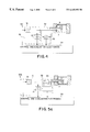
- FIG. 5 a shows another possible design of a high-frequency electronic system used to detect the direction of a predetermined, moving part within the circuit according to an embodiment of the present invention
- FIG. 5 b shows another possible design of a high-frequency electronic system used to detect the direction of a predetermined, moving part within the circuit according to an embodiment of the present invention
- FIG. 6 shows another possible design of a high-frequency electronic system used to measure the distance according to an embodiment of the present invention
- FIG. 1 shows a possible application of the proposed distance-measuring device, which can be used in a piston-rod cylinder run by a linear drive either hydraulically or pneumatically.
- a sensor arrangement 6 is situated axial-symmetrically to piston rod 2 in a bearing cap 4 for the piston rod 2 .
- this design is defined by the piston-rod 2 , the piston 11 , a cylinder wall 3 , and the bearing cap 4 .
- a coupling probe 7 which is part of the sensor device 6 , is integrated into the bearing cap 4 and is directed at the circuit 5 .
- conduits 13 integrated into the bearing cap 4 for the power supply wiring of the sensor arrangement. Those conduits end in a plug-in connection 9 on the periphery of the bearing cap 4 .
- FIG. 2 shows a frontal view of the bearing cap 4 . It shows the sensor arrangement 6 contained in the proposed distance-measuring device. The design shown in FIG. 2 has been developed for the use with a circular piston.
- the sensor arrangement 6 includes a ceramic disc 21 , which has the coupling probe 7 on its front side. The back side of the ceramic disc 21 serves as a carrier for the electronics elements.
- the transmitter-receiver lead and the coupling probe 7 are connected preferably through a galvanic coupling or an aperture coupling.
- a matching network 25 was included.
- the matching network is situated between the introductory point, which is predetermined by the contact 23 , and the coupling probe 7 .
- FIG. 3 shows the potential influence matching network 25 can have on a frequency distribution. It is obvious that matching network 25 doubles the range of frequencies that can be tuned, e.g. the half-width.
- the ceramic disc 21 does not necessarily have to extend around the piston-rod. It may also consist of a small, circular substrate, which is attached non-symmetrically to a section of the piston.
- the coupling probe may also consist of several, e.g. two, contacts and a piece of printed line on the front side of the substrate. The lead connects the two contacts.
- magnetic coupling probe 7 consists of a piece of coaxial lead; for higher frequencies a so-called semi-rigid lead is preferable.
- the coaxial lead is run mechanically through the bearing cap.
- the open internal-lead forms a small loop and is dissolved at the bearing cap and therefore short-circuited.
- the magnetic probe can be designed as a printed strip conductor.
- the wiring is run around the piston-rods star-shaped from the inside out.
- the contact wiring connects the electronics elements on the backside of the substrate with the printed strip conductor on the front side.
- the contact 23 is at the internal end of the printed strip conductor, at the external end the lead is connected to the cylinder casing.
- Further designs, e.g. including a slot coupling, are conceivable. Other than that, all possible variations can be used, with regard to the coaxial symmetry, like the electric coupling probe.
- FIG. 4 shows high-frequency electronics 30 and control and evaluation electronics 33 .
- the coupling probe 7 is controlled by an oscillator 31 , preferably a voltage-controlled oscillator (VCO.)
- VCO voltage-controlled oscillator
- the predetermined voltage is created by the control and evaluation electronics 33 through an ascent-control.
- the transmission signal is introduced into the circuit through a magnetic or an electric coupling probe 7 .
- a magnetic or an electric coupling probe 7 First, one measures the absolute distance between the absolute introductory point and the piston. To do this, the time delay of the transmission signal is measured and processed. The result is a correlation according to Equation 1.
- the frequency of the received transmission signal is lowered in mixer 35 .
- processing this signal provides the absolute distance between the introductory point and the position of the piston or a predetermined section of the circuit with an accuracy of the half-wavelength of the transmission signal.
- This procedure can be called seek-method.
- a continuous wave signal is coupled into the cylinder.
- a static wave forms.
- This static wave shifts with the movement of the piston. The shift can be measured by processing the phases of the signal, the frequency of which has been lowered. This method makes it possible to determine the distance to the piston with accuracy in the sub-millimeter range.
- the high-frequency electronics 30 are divided into a transmission branch 51 and a receiver branch 52 .
- the high-frequency electronics 30 consist of a voltage-controlled oscillator 31 (VCO) and one or more (frequency) dividers 37 .
- the frequency of the oscillator 31 is tuned to a value of, for example, between 4 and 6 GHz, through the predetermined voltage of a Varactor-diode.
- Part of the energy is resistively extracted from the transmission branch 51 and shunt through a frequency divider 37 , e.g. to 30 MHz, so that the transmission frequency is known at all times.
- the receiver branch 52 consists of a mixer 35 , which transforms the signal by mixing it with a transmission signal in the frequency range of up to a few kHz-signals. Since only a continuous wave signal is sent during the Track-Phase, the mixer 35 has to be a DC-coupled one.
- high-frequency electronics 30 A include an arrangement of detector-diodes replaces the mixer 35 shown in FIG. 4 .
- detector-diodes replaces the mixer 35 shown in FIG. 4 .
- the distance between the individual diodes derives from the following Equation 2:
- n 1, 2, . . .
- the frequency of the oscillator 31 is modulated, e.g. within a bandwidth of 15 GHz.
- the distance of the coupling probe 7 to the cylinder-piston can be determined by calculating a FFT (Fast-Fourier-Transformation) and by subsequently calculating the DFT (Discrete-Fourier-Transformation) of the video-signal. This method is accurate to the half-wavelength. Other methods are a simple zero-coefficient count or a minimum-count or a maximum-count.
- Length of the cylinder n ⁇ (Speed of Light/2) ⁇ frequency deviation
- the frequency of the VCO 31 is controlled through a micro-controller or through a discrete electronics system.
- a part of the transmission signal is extracted from the transmission branch 51 , for example resistively.
- the frequency of the transmission signal can be reduced by at least frequency divider 37 to a degree that makes it possible to determine the resulting frequency by using a simple frequency counter.
- the deviation between the actual frequency and the desired frequency of the oscillator 31 is regulated by changing the predetermined voltage at the oscillator 31 .
- the specific voltage is displayed through a digital/analog transformation. This procedure for determining the frequency-adjustment is called “static frequency-adjustment.”
- FIG. 5 b shows another possible method to determine a distance and to detect a direction at the same time.
- high frequency electronics 30 B include an In-Phase/Quadrature (IQ) detector used as a receiver instead of the mixer 35 (shown in FIG. 4) and an arrangement of detector-diodes 45 (shown in FIG. 5 a .)
- the IQ detector consists of two mixers 55 and 65 . The local oscillators of these mixers show a phase-misalignment of 90°.
- FIG. 6 shows high frequency electronics 30 C capable of a dynamic frequency-adjustment.
- the VCO-frequency which has been diverted by the frequency-divider 37 , does not constitute the total quantity. Instead, it is used in a frequency- and phase control and forms a loop.
- a direct digital synthesizer (DDS) 71 is tuned to a specific frequency by, for example, a micro-controller. As a reference variable, this frequency passes into the loop through a phase discriminator.
- the phase discriminator 73 distinguishes/splits the signal coming from the digital synthesizer 71 from the diverted frequency signal.
- the sensor switches to the Track-Mode. This not only increases the accuracy of the measuring but also makes possible the highly dynamic tracking of the piston in operation.
- a continuous wave signal is transmitted.
- a static wave forms in the cylinder.
- the change of the wave in the receiver can be evaluated/processed by the connected electronics system after its frequency has been lowered to the base-band, e.g. from 0 kHz to 100 kHz, by the IQ-detector described earlier, or an arrangement of detector-diodes 45 , or a mixer 35 .
- the Search-Mode is not necessary.
- micro-controller and the design of the cylinder allow for a large variety of possible electrical and mechanical models, as well as for the implementation of additional functions.
- the arrangement of electric connections can be places at any spot on the stationary parts of the cylinder.
- the internal supply takes place through special conduits in the profile of the casing.
- This interface may consist of LEC, LCD displays. It allows for the tuning of connections by Teach-In buttons/keys or a potentiometer.
- this interface can be located remotely from the cylinder. This improves the accessibility.
- the sensor-system used in the distance-measuring device enables additional functions. These include free configuration of outlets, additional direct over further components, e.g. connected valves or regulators, as well as a bus connection node. ‘Free configuration of outlets’ means that, for example, each circuit outlet can be modified as a failure message, for the external detection of broken cable, as a service-interval display, or as an analog-outlet freely definable characteristic.
- the electric connection should preferably be plug-in connection.
- an additional, modulated, bi-directional communication signal can be superimposed on the voltage-supply leads. This allows for a parameterization or an arrangement with external devices without further effort.
- Apart from this design one can conceive of a pure bus connection system. Ideally, this system should already be integrated through the pneumatic connections. Moreover, the wireless transmission of signals is possible.
- a remote, i.e. not integrated, processing system increases the applicability of the device significantly, particularly in the high- and low-temperature range.
- Strip conductors or high-frequency coaxial leads connect the coupling probe with the processing system. Consequently, there are no more active electronic components on or inside the cylinder; the device can be used easily in the high-temperature range.
- the proposed corresponding method for measuring a distance has another advantage in the field of volume measuring, in particular with regard to separating layers. If there are several liquids with different dielectric constants within the circuit, e.g. the diving tube of a tank, the border layer between the liquids can be determined easily.
- this method can be used frequently in oil tanks. Over time, condensed water forms on the bottom of the tank. It has to be removed without having to empty the tank.
Abstract
Description
Claims (22)
Applications Claiming Priority (7)
| Application Number | Priority Date | Filing Date | Title |
|---|---|---|---|
| DE19755648 | 1997-12-15 | ||
| DE19755648 | 1997-12-15 | ||
| DE19814448 | 1998-03-31 | ||
| DE19814448 | 1998-03-31 | ||
| DE19833220A DE19833220A1 (en) | 1997-12-15 | 1998-07-23 | Distance measuring device and method for determining a distance |
| DE19833220 | 1998-07-23 | ||
| PCT/DE1998/003674 WO1999031463A2 (en) | 1997-12-15 | 1998-12-15 | Distance measuring device and method for determining a distance |
Publications (1)
| Publication Number | Publication Date |
|---|---|
| US6445193B1 true US6445193B1 (en) | 2002-09-03 |
Family
ID=27218020
Family Applications (1)
| Application Number | Title | Priority Date | Filing Date |
|---|---|---|---|
| US09/581,388 Expired - Fee Related US6445193B1 (en) | 1997-12-15 | 1998-12-15 | Distance measuring device and method for determining a distance |
Country Status (5)
| Country | Link |
|---|---|
| US (1) | US6445193B1 (en) |
| EP (1) | EP1040316B1 (en) |
| DE (1) | DE59814105D1 (en) |
| ES (1) | ES2296351T3 (en) |
| WO (1) | WO1999031463A2 (en) |
Cited By (13)
| Publication number | Priority date | Publication date | Assignee | Title |
|---|---|---|---|---|
| WO2004053340A1 (en) * | 2002-12-11 | 2004-06-24 | Rosemount Inc. | Hydraulic piston position sensor |
| US20040239339A1 (en) * | 2003-03-07 | 2004-12-02 | Fred Bassali | Novel microwave measurement system for piston displacement |
| US20040263383A1 (en) * | 2003-06-27 | 2004-12-30 | Makita Corporation | Radar device and method of measuring distance and reflecting factor |
| EP1538424A1 (en) * | 2003-12-04 | 2005-06-08 | Festo AG & Co | Microwave based position measurement system for an electrodynamic direct drive |
| US20050139063A1 (en) * | 2002-06-07 | 2005-06-30 | Thomas Reininger | Contraction unit with position sensor device |
| US20050191027A1 (en) * | 2002-02-13 | 2005-09-01 | Gunther Trummer | Distance measuring device and method for determining a distance |
| US20060290368A1 (en) * | 2003-05-06 | 2006-12-28 | Scorpion Technologies Ag | Circuit board test device comprising contact needles which are driven in diagonally protruding manner |
| US20070035310A1 (en) * | 2005-08-11 | 2007-02-15 | Festo Ag & Co | Actuator device with a microwave position detecting device |
| US20090033545A1 (en) * | 2007-08-01 | 2009-02-05 | Pilcher Jr Michael Eugene | Wireless System Using Continuous Wave Phase Measurement for High-Precision Distance Measurement |
| US20110063160A1 (en) * | 2007-08-16 | 2011-03-17 | Guenther Trummer | Double piston rod |
| US20120019409A1 (en) * | 2008-11-14 | 2012-01-26 | Guenther Trummer | Distance measuring apparatus and method for calculating a distance in a conducting structure |
| US20170108104A1 (en) * | 2015-10-16 | 2017-04-20 | Meritor Heavy Vehicle Systems Cameri Spa | Differential Lock Actuator |
| US10634515B2 (en) | 2015-10-02 | 2020-04-28 | Liebherr-Elektronik Gmbh | Apparatus and method for the position determination of a cylinder piston |
Families Citing this family (7)
| Publication number | Priority date | Publication date | Assignee | Title |
|---|---|---|---|---|
| DE102004057769A1 (en) * | 2004-11-30 | 2006-06-01 | Mts Mikrowellen-Technologie Und Sensoren Gmbh | Distance measurement device with electronic analysis and sensor units comprises a conductor structure with a coupling block connecting a high-frequency transceiver via a wave guide to a coupling probe |
| DE102007009094B4 (en) * | 2007-02-24 | 2009-11-26 | Festo Ag & Co. Kg | Actuator with position measuring device |
| EP2017644B1 (en) | 2007-07-20 | 2010-01-13 | Festo AG & Co. KG | Method and measuring device for recording the piston position of a piston in a liquid cylinder via a microwave coupling sensor |
| EP2045619A1 (en) * | 2007-09-27 | 2009-04-08 | Festo AG & Co. KG | Fluid cylinder with a microwave position detecting assembly for the piston |
| DE102008064259A1 (en) | 2008-12-20 | 2010-07-01 | Festo Ag & Co. Kg | Fluidic cylinder with a microwave measuring arrangement and method for detecting at least one parameter |
| DE102013018808A1 (en) | 2013-11-11 | 2015-05-13 | Astyx Gmbh | Distance measuring device for determining a distance and method for determining the distance |
| DE102018212789A1 (en) | 2018-07-31 | 2020-02-06 | Astyx Gmbh | Device Connection structure between evaluation electronics and probe in cylinder systems |
Citations (5)
| Publication number | Priority date | Publication date | Assignee | Title |
|---|---|---|---|---|
| WO1993001470A1 (en) | 1991-07-05 | 1993-01-21 | Caterpillar Inc. | Multiplexed radio frequency linear position sensor system |
| US5325095A (en) | 1992-07-14 | 1994-06-28 | The United States Of America As Represented By The United States Department Of Energy | Stepped frequency ground penetrating radar |
| US5519326A (en) * | 1991-12-23 | 1996-05-21 | Caterpillar Inc. | Linear position sensor using a coaxial resonant cavity |
| US5596325A (en) | 1995-07-07 | 1997-01-21 | Nonlinear Technologies, Inc. | FM-CW radar transceiver |
| US5724041A (en) * | 1994-11-24 | 1998-03-03 | The Furukawa Electric Co., Ltd. | Spread spectrum radar device using pseudorandom noise signal for detection of an object |
Family Cites Families (1)
| Publication number | Priority date | Publication date | Assignee | Title |
|---|---|---|---|---|
| DE3236939C2 (en) * | 1982-10-06 | 1985-07-25 | Licentia Patent-Verwaltungs-Gmbh, 6000 Frankfurt | Arrangement for determining the top dead center of internal combustion engine pistons |
-
1998
- 1998-12-15 ES ES98966209T patent/ES2296351T3/en not_active Expired - Lifetime
- 1998-12-15 US US09/581,388 patent/US6445193B1/en not_active Expired - Fee Related
- 1998-12-15 DE DE59814105T patent/DE59814105D1/en not_active Expired - Lifetime
- 1998-12-15 WO PCT/DE1998/003674 patent/WO1999031463A2/en active IP Right Grant
- 1998-12-15 EP EP98966209A patent/EP1040316B1/en not_active Revoked
Patent Citations (5)
| Publication number | Priority date | Publication date | Assignee | Title |
|---|---|---|---|---|
| WO1993001470A1 (en) | 1991-07-05 | 1993-01-21 | Caterpillar Inc. | Multiplexed radio frequency linear position sensor system |
| US5519326A (en) * | 1991-12-23 | 1996-05-21 | Caterpillar Inc. | Linear position sensor using a coaxial resonant cavity |
| US5325095A (en) | 1992-07-14 | 1994-06-28 | The United States Of America As Represented By The United States Department Of Energy | Stepped frequency ground penetrating radar |
| US5724041A (en) * | 1994-11-24 | 1998-03-03 | The Furukawa Electric Co., Ltd. | Spread spectrum radar device using pseudorandom noise signal for detection of an object |
| US5596325A (en) | 1995-07-07 | 1997-01-21 | Nonlinear Technologies, Inc. | FM-CW radar transceiver |
Non-Patent Citations (1)
| Title |
|---|
| Annonymous, "Microwave Piston Position Detection", Research Disclosure, Kenneth Mason Publications Ltd. (Hampshire, England), No. 279, p. 435, (Jul. 20, 1987). |
Cited By (33)
| Publication number | Priority date | Publication date | Assignee | Title |
|---|---|---|---|---|
| US7095944B2 (en) * | 2002-02-13 | 2006-08-22 | Mikrowellen-Technologie Und Sensoren Gmbh | Distance measuring device and method for determining a distance |
| US20050191027A1 (en) * | 2002-02-13 | 2005-09-01 | Gunther Trummer | Distance measuring device and method for determining a distance |
| US20070003210A1 (en) * | 2002-02-13 | 2007-01-04 | Gunther Trummer | Distance measuring device and method for determining a distance |
| US7433573B2 (en) * | 2002-02-13 | 2008-10-07 | Astyx Gmbh | Distance measuring device and method for determining a distance |
| US7104182B2 (en) * | 2002-06-07 | 2006-09-12 | Festo Ag & Co. | Contractile unit having a position sensor means |
| US20050139063A1 (en) * | 2002-06-07 | 2005-06-30 | Thomas Reininger | Contraction unit with position sensor device |
| WO2004053340A1 (en) * | 2002-12-11 | 2004-06-24 | Rosemount Inc. | Hydraulic piston position sensor |
| CN1309963C (en) * | 2002-12-11 | 2007-04-11 | 罗斯蒙德公司 | Hydraulic piston position sensor |
| US20040239339A1 (en) * | 2003-03-07 | 2004-12-02 | Fred Bassali | Novel microwave measurement system for piston displacement |
| US7466144B2 (en) * | 2003-03-07 | 2008-12-16 | Fred Bassali | Microwave measurement system for piston displacement |
| US7098671B2 (en) * | 2003-03-07 | 2006-08-29 | Fred Bassali | Microwave measurement system for piston displacement |
| US20070170930A1 (en) * | 2003-03-07 | 2007-07-26 | Fred Bassali | Novel microwave measurement system for piston displacement |
| US20060290368A1 (en) * | 2003-05-06 | 2006-12-28 | Scorpion Technologies Ag | Circuit board test device comprising contact needles which are driven in diagonally protruding manner |
| US7336087B2 (en) * | 2003-05-06 | 2008-02-26 | Scorpion Technologies Ag | Circuit board test device comprising contact needles which are driven in diagonally protruding manner |
| US7009552B2 (en) * | 2003-06-27 | 2006-03-07 | Makita Corporation | Radar device and method of measuring distance and reflecting factor |
| US20040263383A1 (en) * | 2003-06-27 | 2004-12-30 | Makita Corporation | Radar device and method of measuring distance and reflecting factor |
| US7323798B2 (en) * | 2003-12-04 | 2008-01-29 | Festo Ag & Co. | Microwave displacement measurement system for an electrodynamic direct drive |
| US20050121985A1 (en) * | 2003-12-04 | 2005-06-09 | Festo Ag & Co | Microwave displacement measurement system for an electrodynamic direct drive |
| EP1538424A1 (en) * | 2003-12-04 | 2005-06-08 | Festo AG & Co | Microwave based position measurement system for an electrodynamic direct drive |
| US20070035310A1 (en) * | 2005-08-11 | 2007-02-15 | Festo Ag & Co | Actuator device with a microwave position detecting device |
| US7451684B2 (en) * | 2005-08-11 | 2008-11-18 | Festo Ag & Co. Kg | Actuator device with a microwave position detecting device |
| US20090033545A1 (en) * | 2007-08-01 | 2009-02-05 | Pilcher Jr Michael Eugene | Wireless System Using Continuous Wave Phase Measurement for High-Precision Distance Measurement |
| US7504992B2 (en) | 2007-08-01 | 2009-03-17 | Southwest Research Institute | Wireless system using continuous wave phase measurement for high-precision distance measurement |
| US8362788B2 (en) * | 2007-08-16 | 2013-01-29 | Astyx Gmbh | Double piston rod |
| US20110063160A1 (en) * | 2007-08-16 | 2011-03-17 | Guenther Trummer | Double piston rod |
| US20130113501A1 (en) * | 2007-08-16 | 2013-05-09 | Astyx Gmbh | Double piston rod |
| US9377289B2 (en) * | 2007-08-16 | 2016-06-28 | Astyx Gmbh | Double piston rod |
| US20120019409A1 (en) * | 2008-11-14 | 2012-01-26 | Guenther Trummer | Distance measuring apparatus and method for calculating a distance in a conducting structure |
| US9267823B2 (en) * | 2008-11-14 | 2016-02-23 | Astyx Gmbh | Distance measuring apparatus and method for calculating a distance in a conducting structure |
| US9625575B2 (en) | 2008-11-14 | 2017-04-18 | Astyx Gmbh | Distance measuring apparatus and method for calculating a distance in a conducting structure |
| US10634515B2 (en) | 2015-10-02 | 2020-04-28 | Liebherr-Elektronik Gmbh | Apparatus and method for the position determination of a cylinder piston |
| US20170108104A1 (en) * | 2015-10-16 | 2017-04-20 | Meritor Heavy Vehicle Systems Cameri Spa | Differential Lock Actuator |
| US9903457B2 (en) * | 2015-10-16 | 2018-02-27 | Meritor Heavy Vehicle Systems Cameri Spa | Differential lock actuator |
Also Published As
| Publication number | Publication date |
|---|---|
| WO1999031463A3 (en) | 1999-08-12 |
| ES2296351T3 (en) | 2008-04-16 |
| WO1999031463A2 (en) | 1999-06-24 |
| DE59814105D1 (en) | 2007-11-15 |
| EP1040316B1 (en) | 2007-10-03 |
| EP1040316A2 (en) | 2000-10-04 |
Similar Documents
| Publication | Publication Date | Title |
|---|---|---|
| US6445193B1 (en) | Distance measuring device and method for determining a distance | |
| EP2283382B1 (en) | High sensitivity frequency modulated radar level gauge system | |
| JP5684822B2 (en) | Digitally controlled UWB millimeter wave radar | |
| US7095944B2 (en) | Distance measuring device and method for determining a distance | |
| US6606904B2 (en) | Filling level gage | |
| US7589664B2 (en) | Circuit for multifrequency band radar level gauge | |
| US9371847B2 (en) | Distance measuring device and method for determining a distance, and a suitable reflective member | |
| US20090085794A1 (en) | Radar level gauge system | |
| Vogt et al. | Silo and tank vision: Applica? tions, challenges, and technical solutions for radar measurement of liquids and bulk solids in tanks and silos | |
| DE19833220A1 (en) | Distance measuring device and method for determining a distance | |
| US4978963A (en) | RF signal direction finding apparatus | |
| JPH09257909A (en) | Monostatic homodyne radar system | |
| US20190316951A1 (en) | Tank Multi-Level Measurement Using Through the Air Millimeter Wave Radar | |
| US7012437B2 (en) | Device for the determination and/or monitoring of the filling level of the charge in a container | |
| EP3811040A1 (en) | Radar level gauge | |
| Fericean et al. | Microwave displacement sensor for hydraulic devices | |
| US10534077B2 (en) | Proximity sensor and method for measuring the distance from an object | |
| US8072367B1 (en) | Organically reactive cell for underground sensing (ORCUS) and system | |
| FI91809C (en) | Method and apparatus for measuring the speed of a moving object using the Doppler offset of electromagnetic radiation | |
| EP3425351B1 (en) | Radar level gauge system having longitudinally open two-conductor probe, and method of assembly of the level gauge system | |
| EP3857183B1 (en) | System and method for determining level and density distribution | |
| EP0367487B1 (en) | RF signal direction finding apparatus | |
| CN215491512U (en) | Single antenna displacement measuring device | |
| Okubo et al. | Experimental verification of measurement principle in standing wave radar capable of measuring distances down to zero meters | |
| Rutkowski et al. | A planar microwave frequency discriminator |
Legal Events
| Date | Code | Title | Description |
|---|---|---|---|
| AS | Assignment |
Owner name: MIKROWELLEN-TECHNOLOGIE UND SENSOREN GMBH, GERMANY Free format text: ASSIGNMENT OF ASSIGNORS INTEREST;ASSIGNORS:TRUMMER, GUENTHER;SEITZ, ARMIN;NEUGEBAUER, ALFRED;AND OTHERS;REEL/FRAME:011197/0045 Effective date: 20000823 |
|
| AS | Assignment |
Owner name: MIKROWELLEN-TECHNOLOGIE UND SENSOREN GMBH, GERMANY Free format text: CORRECTIVE ASSIGNMENT TO ADD 2ND ASSIGNEE PREVIOUSLY OMITTED ON A DOCUMENT RECORDED ON REEL 011197, FRAME 0045;ASSIGNORS:TRUMMER, GUENTHER;SEITZ, ARMIN;NEUGEBAUER, ALFRED;AND OTHERS;REEL/FRAME:011616/0648 Effective date: 20000823 Owner name: FESTO AG & CO., GERMANY Free format text: CORRECTIVE ASSIGNMENT TO ADD 2ND ASSIGNEE PREVIOUSLY OMITTED ON A DOCUMENT RECORDED ON REEL 011197, FRAME 0045;ASSIGNORS:TRUMMER, GUENTHER;SEITZ, ARMIN;NEUGEBAUER, ALFRED;AND OTHERS;REEL/FRAME:011616/0648 Effective date: 20000823 |
|
| REMI | Maintenance fee reminder mailed | ||
| FPAY | Fee payment |
Year of fee payment: 4 |
|
| SULP | Surcharge for late payment | ||
| FEPP | Fee payment procedure |
Free format text: PAYOR NUMBER ASSIGNED (ORIGINAL EVENT CODE: ASPN); ENTITY STATUS OF PATENT OWNER: LARGE ENTITY |
|
| FPAY | Fee payment |
Year of fee payment: 8 |
|
| AS | Assignment |
Owner name: ASTYX GMBH, GERMANY Free format text: CHANGE OF NAME;ASSIGNOR:MIKROWELLEN-TECHNOLOGIE UND SENSOREN GMBH;REEL/FRAME:024823/0573 Effective date: 20060525 |
|
| REMI | Maintenance fee reminder mailed | ||
| LAPS | Lapse for failure to pay maintenance fees | ||
| STCH | Information on status: patent discontinuation |
Free format text: PATENT EXPIRED DUE TO NONPAYMENT OF MAINTENANCE FEES UNDER 37 CFR 1.362 |
|
| FP | Lapsed due to failure to pay maintenance fee |
Effective date: 20140903 |