US6454708B1 - Portable remote patient telemonitoring system using a memory card or smart card - Google Patents
Portable remote patient telemonitoring system using a memory card or smart card Download PDFInfo
- Publication number
- US6454708B1 US6454708B1 US09/591,597 US59159700A US6454708B1 US 6454708 B1 US6454708 B1 US 6454708B1 US 59159700 A US59159700 A US 59159700A US 6454708 B1 US6454708 B1 US 6454708B1
- Authority
- US
- United States
- Prior art keywords
- data
- health parameter
- parameter data
- monitoring station
- base station
- Prior art date
- Legal status (The legal status is an assumption and is not a legal conclusion. Google has not performed a legal analysis and makes no representation as to the accuracy of the status listed.)
- Expired - Fee Related, expires
Links
Images


Classifications
-
- A—HUMAN NECESSITIES
- A61—MEDICAL OR VETERINARY SCIENCE; HYGIENE
- A61B—DIAGNOSIS; SURGERY; IDENTIFICATION
- A61B5/00—Measuring for diagnostic purposes; Identification of persons
- A61B5/68—Arrangements of detecting, measuring or recording means, e.g. sensors, in relation to patient
- A61B5/6801—Arrangements of detecting, measuring or recording means, e.g. sensors, in relation to patient specially adapted to be attached to or worn on the body surface
- A61B5/683—Means for maintaining contact with the body
- A61B5/6831—Straps, bands or harnesses
-
- A—HUMAN NECESSITIES
- A61—MEDICAL OR VETERINARY SCIENCE; HYGIENE
- A61B—DIAGNOSIS; SURGERY; IDENTIFICATION
- A61B5/00—Measuring for diagnostic purposes; Identification of persons
- A61B5/0002—Remote monitoring of patients using telemetry, e.g. transmission of vital signals via a communication network
- A61B5/0015—Remote monitoring of patients using telemetry, e.g. transmission of vital signals via a communication network characterised by features of the telemetry system
- A61B5/0022—Monitoring a patient using a global network, e.g. telephone networks, internet
-
- A—HUMAN NECESSITIES
- A61—MEDICAL OR VETERINARY SCIENCE; HYGIENE
- A61B—DIAGNOSIS; SURGERY; IDENTIFICATION
- A61B5/00—Measuring for diagnostic purposes; Identification of persons
- A61B5/02—Detecting, measuring or recording pulse, heart rate, blood pressure or blood flow; Combined pulse/heart-rate/blood pressure determination; Evaluating a cardiovascular condition not otherwise provided for, e.g. using combinations of techniques provided for in this group with electrocardiography or electroauscultation; Heart catheters for measuring blood pressure
- A61B5/0205—Simultaneously evaluating both cardiovascular conditions and different types of body conditions, e.g. heart and respiratory condition
- A61B5/02055—Simultaneously evaluating both cardiovascular condition and temperature
-
- A—HUMAN NECESSITIES
- A61—MEDICAL OR VETERINARY SCIENCE; HYGIENE
- A61B—DIAGNOSIS; SURGERY; IDENTIFICATION
- A61B5/00—Measuring for diagnostic purposes; Identification of persons
- A61B5/74—Details of notification to user or communication with user or patient ; user input means
- A61B5/742—Details of notification to user or communication with user or patient ; user input means using visual displays
- A61B5/7435—Displaying user selection data, e.g. icons in a graphical user interface
-
- G—PHYSICS
- G16—INFORMATION AND COMMUNICATION TECHNOLOGY [ICT] SPECIALLY ADAPTED FOR SPECIFIC APPLICATION FIELDS
- G16H—HEALTHCARE INFORMATICS, i.e. INFORMATION AND COMMUNICATION TECHNOLOGY [ICT] SPECIALLY ADAPTED FOR THE HANDLING OR PROCESSING OF MEDICAL OR HEALTHCARE DATA
- G16H10/00—ICT specially adapted for the handling or processing of patient-related medical or healthcare data
- G16H10/60—ICT specially adapted for the handling or processing of patient-related medical or healthcare data for patient-specific data, e.g. for electronic patient records
- G16H10/65—ICT specially adapted for the handling or processing of patient-related medical or healthcare data for patient-specific data, e.g. for electronic patient records stored on portable record carriers, e.g. on smartcards, RFID tags or CD
-
- G—PHYSICS
- G16—INFORMATION AND COMMUNICATION TECHNOLOGY [ICT] SPECIALLY ADAPTED FOR SPECIFIC APPLICATION FIELDS
- G16H—HEALTHCARE INFORMATICS, i.e. INFORMATION AND COMMUNICATION TECHNOLOGY [ICT] SPECIALLY ADAPTED FOR THE HANDLING OR PROCESSING OF MEDICAL OR HEALTHCARE DATA
- G16H40/00—ICT specially adapted for the management or administration of healthcare resources or facilities; ICT specially adapted for the management or operation of medical equipment or devices
- G16H40/60—ICT specially adapted for the management or administration of healthcare resources or facilities; ICT specially adapted for the management or operation of medical equipment or devices for the operation of medical equipment or devices
- G16H40/67—ICT specially adapted for the management or administration of healthcare resources or facilities; ICT specially adapted for the management or operation of medical equipment or devices for the operation of medical equipment or devices for remote operation
-
- A—HUMAN NECESSITIES
- A61—MEDICAL OR VETERINARY SCIENCE; HYGIENE
- A61B—DIAGNOSIS; SURGERY; IDENTIFICATION
- A61B2560/00—Constructional details of operational features of apparatus; Accessories for medical measuring apparatus
- A61B2560/02—Operational features
- A61B2560/0204—Operational features of power management
- A61B2560/0209—Operational features of power management adapted for power saving
-
- A—HUMAN NECESSITIES
- A61—MEDICAL OR VETERINARY SCIENCE; HYGIENE
- A61B—DIAGNOSIS; SURGERY; IDENTIFICATION
- A61B2560/00—Constructional details of operational features of apparatus; Accessories for medical measuring apparatus
- A61B2560/04—Constructional details of apparatus
- A61B2560/0406—Constructional details of apparatus specially shaped apparatus housings
- A61B2560/0412—Low-profile patch shaped housings
-
- A—HUMAN NECESSITIES
- A61—MEDICAL OR VETERINARY SCIENCE; HYGIENE
- A61B—DIAGNOSIS; SURGERY; IDENTIFICATION
- A61B2560/00—Constructional details of operational features of apparatus; Accessories for medical measuring apparatus
- A61B2560/04—Constructional details of apparatus
- A61B2560/0475—Special features of memory means, e.g. removable memory cards
-
- A—HUMAN NECESSITIES
- A61—MEDICAL OR VETERINARY SCIENCE; HYGIENE
- A61B—DIAGNOSIS; SURGERY; IDENTIFICATION
- A61B5/00—Measuring for diagnostic purposes; Identification of persons
- A61B5/0002—Remote monitoring of patients using telemetry, e.g. transmission of vital signals via a communication network
- A61B5/0004—Remote monitoring of patients using telemetry, e.g. transmission of vital signals via a communication network characterised by the type of physiological signal transmitted
- A61B5/0006—ECG or EEG signals
-
- A—HUMAN NECESSITIES
- A61—MEDICAL OR VETERINARY SCIENCE; HYGIENE
- A61B—DIAGNOSIS; SURGERY; IDENTIFICATION
- A61B5/00—Measuring for diagnostic purposes; Identification of persons
- A61B5/103—Detecting, measuring or recording devices for testing the shape, pattern, colour, size or movement of the body or parts thereof, for diagnostic purposes
- A61B5/11—Measuring movement of the entire body or parts thereof, e.g. head or hand tremor, mobility of a limb
-
- A—HUMAN NECESSITIES
- A61—MEDICAL OR VETERINARY SCIENCE; HYGIENE
- A61B—DIAGNOSIS; SURGERY; IDENTIFICATION
- A61B5/00—Measuring for diagnostic purposes; Identification of persons
- A61B5/145—Measuring characteristics of blood in vivo, e.g. gas concentration, pH value; Measuring characteristics of body fluids or tissues, e.g. interstitial fluid, cerebral tissue
- A61B5/1455—Measuring characteristics of blood in vivo, e.g. gas concentration, pH value; Measuring characteristics of body fluids or tissues, e.g. interstitial fluid, cerebral tissue using optical sensors, e.g. spectral photometrical oximeters
-
- A—HUMAN NECESSITIES
- A61—MEDICAL OR VETERINARY SCIENCE; HYGIENE
- A61B—DIAGNOSIS; SURGERY; IDENTIFICATION
- A61B5/00—Measuring for diagnostic purposes; Identification of persons
- A61B5/72—Signal processing specially adapted for physiological signals or for diagnostic purposes
- A61B5/7232—Signal processing specially adapted for physiological signals or for diagnostic purposes involving compression of the physiological signal, e.g. to extend the signal recording period
-
- A—HUMAN NECESSITIES
- A61—MEDICAL OR VETERINARY SCIENCE; HYGIENE
- A61B—DIAGNOSIS; SURGERY; IDENTIFICATION
- A61B5/00—Measuring for diagnostic purposes; Identification of persons
- A61B5/74—Details of notification to user or communication with user or patient ; user input means
- A61B5/742—Details of notification to user or communication with user or patient ; user input means using visual displays
-
- Y—GENERAL TAGGING OF NEW TECHNOLOGICAL DEVELOPMENTS; GENERAL TAGGING OF CROSS-SECTIONAL TECHNOLOGIES SPANNING OVER SEVERAL SECTIONS OF THE IPC; TECHNICAL SUBJECTS COVERED BY FORMER USPC CROSS-REFERENCE ART COLLECTIONS [XRACs] AND DIGESTS
- Y02—TECHNOLOGIES OR APPLICATIONS FOR MITIGATION OR ADAPTATION AGAINST CLIMATE CHANGE
- Y02A—TECHNOLOGIES FOR ADAPTATION TO CLIMATE CHANGE
- Y02A90/00—Technologies having an indirect contribution to adaptation to climate change
- Y02A90/10—Information and communication technologies [ICT] supporting adaptation to climate change, e.g. for weather forecasting or climate simulation
-
- Y—GENERAL TAGGING OF NEW TECHNOLOGICAL DEVELOPMENTS; GENERAL TAGGING OF CROSS-SECTIONAL TECHNOLOGIES SPANNING OVER SEVERAL SECTIONS OF THE IPC; TECHNICAL SUBJECTS COVERED BY FORMER USPC CROSS-REFERENCE ART COLLECTIONS [XRACs] AND DIGESTS
- Y10—TECHNICAL SUBJECTS COVERED BY FORMER USPC
- Y10S—TECHNICAL SUBJECTS COVERED BY FORMER USPC CROSS-REFERENCE ART COLLECTIONS [XRACs] AND DIGESTS
- Y10S128/00—Surgery
- Y10S128/903—Radio telemetry
-
- Y—GENERAL TAGGING OF NEW TECHNOLOGICAL DEVELOPMENTS; GENERAL TAGGING OF CROSS-SECTIONAL TECHNOLOGIES SPANNING OVER SEVERAL SECTIONS OF THE IPC; TECHNICAL SUBJECTS COVERED BY FORMER USPC CROSS-REFERENCE ART COLLECTIONS [XRACs] AND DIGESTS
- Y10—TECHNICAL SUBJECTS COVERED BY FORMER USPC
- Y10S—TECHNICAL SUBJECTS COVERED BY FORMER USPC CROSS-REFERENCE ART COLLECTIONS [XRACs] AND DIGESTS
- Y10S128/00—Surgery
- Y10S128/904—Telephone telemetry
Definitions
- the present invention relates to a system and method for monitoring vital signs and capturing data from a patient remotely using telemonitoring techniques.
- the present invention is a low cost, patient-friendly, ambulatory monitoring system incorporating a low cost memory card or smart card for the remote electronic capture of noninvasive vital signs data including, e.g., full single or multiple lead ECG, respiration rate, SpO 2 , skin temperature, and blood pressure.
- An improved technique for testing the efficacy and safety of a drug and/or therapy is desired which does not require additional visits to the physician. It is desired to develop a technique for collecting data from a human subject at all times during a trial without requiring any visits to the physician's office, thereby eliminating the cost and inconvenience of visiting the physician's office for routine monitoring.
- an improved remote patient monitoring/management system is generally desired whereby useful vital signs data may be obtained from a patient without requiring frequent visits to the physician's office.
- Such remote monitoring/management is particularly desirable for home patient monitoring of patients with chronic illnesses such as congestive heart failure or for post-operative or out-patient monitoring.
- Prior art patient telemetry systems have had limited commercial success for a variety of reasons such as difficulty of use and cost.
- Remote patient monitoring techniques are generally known in which electrodes are placed on the patient to monitor the patient's vital signs and the captured data is transmitted to a remote display for monitoring the patient's condition.
- Remote monitoring systems are known which permit a doctor or nurse to monitor the conditions of several hospitalized patients from a central monitoring site in the hospital.
- sophisticated patient monitoring equipment is used to collect data from the patient, and the collected data is transmitted via wire to the central monitoring site in the hospital.
- wireless systems are problematic in the hospital setting because of the proximity of the respective patients and the amount of interference found in such a setting.
- Physiologic data such as electrocardiographic (ECG) data is collected by a sensor and transmitted by a VHF transmitter to a fixed VHF receiver RF transmitter coupled to the wiring system in the building.
- ECG electrocardiographic
- a RF receiver demodulator monitor is coupled to the building's wiring system at the nurse's station for receiving the physiologic data for patient monitoring and/or data recording.
- the patient requires a transmitter that is carried by the patient for sensing and transmitting the patient's ECG signal to a central base station via wireless link.
- a receiver recovers the original ECG signal from a few patients simultaneously for display.
- Each of the above-described telemetry systems is designed primarily for hospital use and include relatively expensive sensor arrays and processing devices for real-time patient monitoring and diagnosis.
- the real-time monitoring is generally used in an “alarm” mode to capture events, rather than to collect data over a period of time to determine trends which might indicate a more gradual deterioration or improvement in the patient's condition or to predict a forthcoming event.
- these systems require the patient to remain in close proximity to the base stations including the receivers.
- Segalowitz discloses a wireless vital signs monitoring system in U.S. Pat. Nos. 4,981,141; 5,168,874; 5,307,818; and 5,511,553 including aprecordial strip patch including a multi-layer flexible structure for telemetering data by radio frequency or single wire to hardware recording apparatus and a display monitor.
- Microsensors and conductive contact elements (CCEs) are mounted on the strip patch so as to permit simultaneous and continuous detection, processing and transmission of 12-lead ECG, cardiac output, respiration rate, peripheral blood oximetry, temperature of the patient, and ECG fetal heart monitoring via a single wavelength of radio frequency transmission.
- the precordial strip patch used by Segalowitz purportedly transmits vital signs data up to 50 meters, it requires a dual-stage operational amplifier chip, an encoder modulator chip, a wireless transmitter chip including an oscillator, and other costly components such as artificial intelligence software, sound and visual alarms, and a microprocessor.
- the precordial strip patch is relatively expensive to manufacture and operate.
- the emphasis of Segalowitz is on real-time monitoring and alerting of medical personnel to immediate medical needs of the patient.
- Platt et al. also disclose a sensor patch for wireless physiological monitoring of patients in U.S. Pat. No. 5,634,468.
- Platt et al. describe a sensor and system for monitoring ECG signals remotely from patients located in non-hospital sites.
- a sensor patch containing sensing electrodes, signal processing circuitry and radio or infra-red transmission circuitry is attached to the patient's body and preferably worn for at least a week before its power supply is exhausted and the sensor patch is thrown away.
- a receiver at a primary site in the vicinity of the patient receives the data transmitted by the sensor patch and stores the sensed data.
- the patient When the patient feels discomfort or concern, or if the portable unit sounds an alarm, the patient telephones the monitoring station and downloads the stored data from the portable unit via the standard voice telecommunications network.
- the downloaded ECG data is then monitored and analyzed at the monitoring station.
- the receiver in the proximity of the patient may be a portable unit carried around by the patient, where the portable unit includes a receiver, a processor for processing the received data to identify abnormalities, a memory for storing the sensed data, and circuitry for interfacing to a telephone line to send the ECG data signals to the monitoring station.
- the monitoring station decodes the received ECG signals and performs beat and rhythm analysis for classification of the ECG data. If an abnormal condition is discovered, medical personnel in the vicinity of the patient are contacted.
- Platt et al. may collect ECG data from the patient and process it at a remote monitoring station, the data is only collected when the patient initiates the data download. Otherwise, data is lost once the memory in the portable unit is full. No mechanism is provided for continuously collecting data, at all times, in a way which requires little or no patient action.
- Langer et al. disclose a telemetry system for monitoring the heart of a patient in which a patient station includes telemetering apparatus for transmitting the outputs of patient electrodes to a tele-link unit connected to a monitoring station by telephone lines.
- a patient station includes telemetering apparatus for transmitting the outputs of patient electrodes to a tele-link unit connected to a monitoring station by telephone lines.
- Langer et al. transmit ECG data to a central location.
- the Langer et al. system checks the ECG data for predetermined events and automatically calls the monitoring station when such events are detected.
- a similar telemetry system is described by Davis et al. in U.S. Pat. No.
- a telemonitoring system which collects vital signs data from a patient using an inexpensive device that permits the continuous collection of a patient's vital signs data with little or no patient action.
- a data management system is desired which permits the collected data to be reviewed and formatted for use in patient trials and the like. The present invention has been designed to meet these needs in the art.
- the present invention meets the above-mentioned needs in the prior art by providing a portable remote patient telemonitoring system which collects vital signs (health parameter) data from a patient using a disposable sensor device attached to the patient and stores the vital signs data on a memory card or a smart card that may be inserted into the sensor device for data collection and/or transmits the data to a portable data logger or base station unit for processing and storage.
- a memory card is used that stores the vital signs data and is removed and its contents downloaded to a monitoring device for performing processing and monitoring functions.
- the electronics of the disposable sensor device are provided on a removable smart card-type device that may or may not have memory for storing the collected vital signs data.
- the electronics on the smart card may or may not include transmission circuitry for transmitting the vital signs data to a nearby portable data logger or a base station unit.
- Each embodiment of the portable remote telemonitoring system in accordance with the invention is characterized by combinations of the following separate elements, each with different functions within the system.
- the first component is an adhesive, cordless, disposable sensor band with electrode patches, other sensors, and a connector dock for accepting a conventional memory card, such as an MMC memory card, for storing detected vital signs data, or a smart card that contains electronic circuitry and may or may not contain memory. Additional internal memory equivalent or discrete memory may also be available on the memory card or smart card.
- the smart card preferably includes the sensor band's electronics so that the cost of the disposable sensor band may be minimized.
- the sensor band is easy-to-use and is positioned on the patient by the patient. The sensor band is designed to be worn comfortably by the patient for 24 hours, at which time the sensor band may be discarded and replaced by a new sensor band.
- the memory card or smart card is ideally designed to store all vital signs data generated by the patient during that 24 hour period.
- the memory card or smart card is removed from the sensor band before the sensor band is discarded, and the memory card or smart card is either mailed or carried to a remote monitoring station or, more preferably, inserted into a base station which uploads the stored vital signs data to the remote monitoring station. Since the vital signs data is collected on a memory card or smart card received in the sensor band, the patient is free to move around freely while his or her vital signs are being monitored. Once the data stored on the memory card or smart card is uploaded, the memory card or smart card may be used again with another sensor band.
- the second component is a base station having a memory card/smart card reader for accepting the memory card or smart card, reading the vital signs data stored therein, and storing the vital signs data until the stored data is to be uploaded via conventional phone lines to a remote monitoring station.
- the base station may also be designed to capture additional clinical data, such as blood pressure data, to perform data checks, and to process the stored data.
- the base station connects the memory card or smart card, via modem and land or cellular telephone line, to the remote monitoring station. Connections for auxiliary sensors such as a blood pressure cuff extend the number of clinical parameters that can be captured.
- Patient safety is enhanced by the ability of the base station to compare clinical data, e.g. ECG, against given profiles and to indicate violation of preset limits when appropriate or when the base station is programmed to do so. Such violations could be indicated to the patient by audio and/or visual indicators.
- the third component is a remote monitoring station that allows the presentation and review of data (including event flags) forwarded by the sensor band and other sensors and simply requires a standard PC running, e.g., Windows NT.
- ECG analysis software and a user-friendly graphical user interface are provided to remotely analyze the transmitted data and to permit system maintenance and upkeep.
- the patient health parameter data collection and monitoring system of the invention is characterized by a sensor band having a sensor assembly for application to a subject, where the sensor assembly produces health parameter data indicative of values of at least one health parameter of the subject.
- the sensor band in accordance with the invention includes a connector that accepts a memory card, such as a low cost MMC memory card, that includes internal memory for storing the health parameter data produced by the sensor band, or a specially designed smart card that contains the signal processing circuitry (ADC, etc.) as well as any desired memory.
- ADC signal processing circuitry
- the memory card or smart card may be taken or mailed to a remote monitoring station for data download, or, conversely, the memory card or smart card may be inserted into a base station at the patient's location for uploading the health parameter data from the memory card or the smart card to the remote monitoring station via a telecommunications link.
- the remote monitoring station captures the vital signs data and stores it in a database for display and subsequent access.
- the remote monitoring station also processes the health parameter data for medical diagnosis or analysis.
- the remote monitoring station stores the health parameter data in the database with the vital signs data from a plurality of other patients.
- a user interface provides access to the vital signs data in the database for processing, medical diagnosis and/or analysis.
- the smart card also houses the sensor band's electronics so that the electronics may be reusable from one sensor band to the next.
- Such electronics may include a rechargeable power supply that is recharged when the memory card or smart card is inserted into the base station unit for data download.
- the power supply may reside on the sensor band (e.g., in the smart card/memory card connector) and be discarded with the disposable sensor band when the power supply is depleted.
- the sensor band measures full waveform single or multiple lead ECG, full waveform respiration, skin temperature, and motion and stores the measured data in the memory card or smart card.
- Auxiliary sensors are preferably provided at the base station, such auxiliary sensors including, e.g., a blood pressure cuff, a spirometer, and weight scales.
- the user interface at the remote monitoring station may contain full ECG analysis software covering waveform measurements, interval measurements, beat-typing and arrhythmia detection. “Event flags” also may be generated and indicated to the physician for high and low heart rate, high and low respiration rate, high and low temperature, high and low blood pressure or arrhythmias.
- the remote telemonitoring system of the invention is also designed to reduce both the length and the cost of clinical drug trials by providing versatility in data collection with respect to site (in-clinic or domiciliary), time, and volume, and to provide direct, electronic data capture.
- Additional applications include the monitoring of sleep apnea, diabetes, acute or sub-acute infection, asthma, and the like, as well as “remote nurse” applications which provide a live view of the patient's condition.
- the use of a memory card or such a smart card is not well-suited to real-time vital signs monitoring unless the smart card includes transmission circuitry.
- Such transmission circuitry is included in another embodiment of the invention whereby the smart card includes transmission circuitry for broadcasting the vital signs data to a portable data logger or base station unit for remote storage.
- the smart card may or may not contain memory for storing the vital signs data and may or may not include the sensor electronics.
- the inclusion of some memory on the smart card is preferred as it may act as a buffer in the event that the transmission channel with the portable data logger or base station unit is lost for some reason (e.g., the sensor band is out of range).
- FIG. 1 illustrates a presently preferred embodiment of the remote patient monitoring system in accordance with the invention.
- FIG. 2 illustrates a rear view (patient side) of a sensor band including electrodes and sensors for attachment to the patient's body for measuring vital signs data such as full waveform single or multiple lead ECG, full waveform chest respiration, SpO 2 , skin temperature, and motion using the techniques of the invention.
- vital signs data such as full waveform single or multiple lead ECG, full waveform chest respiration, SpO 2 , skin temperature, and motion using the techniques of the invention.
- FIG. 3 illustrates the user interface to the base station unit provided in accordance with the invention.
- FIG. 4A illustrates a remote monitoring embodiment in which a server is used for data acquisition from a plurality of patients and the acquired data is provided to client systems which are connected so as to access the acquired data for analysis.
- FIG. 4B illustrates a remote monitoring embodiment in which the end user has a server for data acquisition from a plurality of patients, where the end user accesses the server directly.
- FIG. 5A illustrates a general block diagram of the system electronics in accordance with a first embodiment whereby a memory card stores the vital signs data.
- FIG. 5B illustrates a general block diagram of the system electronics in accordance with a second embodiment whereby a smart card stores the vital signs data and also includes the sensor electronics.
- FIG. 5C illustrates a general block diagram of the system electronics in accordance with a third embodiment whereby the smart card includes reusable electronics for broadcasting the vital signs data to a personal data logger where the data is stored and/or retransmitted to the base station unit.
- FIG. 5D illustrates a general block diagram of the system electronics in accordance with a fourth embodiment whereby the smart card includes the sensor electronics in addition to the reusable electronics for broadcasting the vital signs data to a personal data logger.
- FIG. 6 illustrates the architecture of the software of the remote monitoring station.
- FIG. 7 illustrates a diagram of the top level uses of the remote monitoring station of the invention.
- FIG. 8 illustrates the modify case properties process implemented by the monitoring station of the invention.
- FIG. 9 illustrates the “review downloaded data from a patient” process implemented by the monitoring station of the invention.
- FIG. 10 illustrates the “review events” process implemented by the monitoring station of the invention.
- FIG. 11A illustrates the case home screen with the sessions available for the selected patient.
- FIG. 11B illustrates the case home screen listing the events which occurred for the selected patient during the selected time interval.
- FIG. 11C illustrates the monitoring setup change screen available for the selected patient.
- FIG. 11D illustrates the patient information listing the patient data for the selected patient.
- FIG. 11E illustrates the auxiliary sensors setup screen available for the selected patient.
- FIG. 11F illustrates the trend data screen for displaying auxiliary sensor data available for the selected patient.
- FIG. 12 illustrates the summary graphs for heart rate, respiration and temperature when the summary button is selected.
- FIGS. 1-12 A system and method with the above-mentioned beneficial features in accordance with a presently preferred exemplary embodiment of the invention will be described below with reference to FIGS. 1-12. It will be appreciated by those of ordinary skill in the art that the description given herein with respect to those figures is for exemplary purposes only and is not intended in any way to limit the scope of the invention. All questions regarding the scope of the invention may be resolved by referring to the appended claims.
- FIG. 1 A presently preferred embodiment of the remote patient telemoritoring system of the invention is illustrated in FIG. 1 .
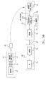
- the system of the invention comprises a disposable multi-parameter sensor band 10 , preferably worn on the patient's chest, for measuring patient vital signs (health parameters) and storing the measured vital signs data in a memory card/smart card 20 and/or transmitting the measured vital signs data to a portable data logger (not shown) carried by the patient, a base station unit 30 which receives the stored vital signs data from the memory card/smart card 20 and transmits the vital signs data over a telecommunications link 40 , and a remote monitoring station 50 which receives the vital signs data from the base station unit 30 via the telecommunications link 40 .
- a disposable multi-parameter sensor band 10 preferably worn on the patient's chest, for measuring patient vital signs (health parameters) and storing the measured vital signs data in a memory card/smart card 20 and/or transmitting the measured vital signs data to a portable data logger (
- the sensor band 10 is designed to extend across the patient's chest and includes electrodes and other sensors (not shown) which are situated so as to measure full waveform single or multiple lead ECG, full waveform chest respiration (using impedance and/or resistance bend sensor), skin temperature, and motion.
- ECG electronic cardiac record
- full waveform chest respiration using impedance and/or resistance bend sensor
- skin temperature skin temperature
- motion e.g., acoustic temperature
- other vital signs such as EEG and blood oxygenation
- Conventional blood oxygenation sensors placed on the finger, wrist, or ear may also provide data through a wire or wireless link to the sensor band 10 .
- the signal processing circuitry 12 receives the sensor data from traces 14 and a directly connected thermistor (not shown) and is powered by, e.g., an alkaline manganese battery pack (not shown) designed to permit the sensor band 10 to collect vital signs data for approximately 30 hours and to store the collected vital signs data in a memory card/smart card 20 connected to the signal processing circuitry 12 through a connector 13 ′ of the connector port 13 disposed atop the signal processing circuitry 12 so as to accept the memory card/smart card 20 .
- the smart card differs from the memory card in that it also includes the signal processing circuitry 12 whereby all the sensor band's electronics are on the smart card 20 .
- the smart card 20 is connected to a connector that is, in turn, connected directly to the traces 14 .
- the batteries for powering the smart card may be housed in the connector and discarded with the used sensor band 10 , or, alternatively, the smart card 20 may include rechargeable battery elements.
- the sensor band 10 is typically removed and disposed of every 24 hours and replaced by a new sensor band 10 .
- the serial number of that sensor band 10 is randomly generated and sent in a repeating cycle for easy tracking of the vital signs data stored in the memory card/smart card 20 .
- the sensor band 10 is designed such that the patient only has to prepare his or her skin, peel back a protective strip over the hydrogel and hydrocolloid adhesive layers which are, in turn, placed over the electrodes, signal processing circuitry 12 , and battery, and stick the sensor band 10 to the prepared skin in a position for measurement of the vital signs such as ECG.
- the sensor band 10 may be provided in a number of sizes sufficient to administer to infants as well as large adults.
- the “V” bend 15 is preferably located between the left and right chest sections so as to allow some movement of the sensor band 10 when it is attached to the chest.
- full waveform ECG data is collected at a 250 Hz sampling frequency from three electrodes: one electrode in portion 16 placed under the patient's left armpit, one electrode in a portion 17 on the right hand side of the chest, and one reference electrode in portion 18 on the left hand side of the chest.
- the ECG data is collected with a resolution of 10 bits.
- Full waveform respiration data is also collected at a 25 Hz sampling frequency using the trans-thoracic impedance method, with a 50 kHz continuous reciprocating current and two electrodes (force and sense) at the left hand side of the chest and two electrodes at the right hand side of the chest.
- the sense electrode on the right hand side of the chest is preferably the same as that used for ECG detection.
- the respiration data has a data resolution of 8 bits. Respiration data (with the same qualities except for 7 bit resolution) may also be collected using a printed carbon on flextrate resistance bend sensor 19 located on the left hand side of the chest.
- One or both methods of respiration measurement may be used for a given patient.
- Skin temperature data is collected at 25 Hz using a thermistor located in portion 16 under the armpit.
- the temperature range is 25 to 45 degrees C. with a reporting accuracy of +/ ⁇ 0.5 degree C., an output sampling frequency of 25 Hz, and data resolution of 6 bits.
- Motion data is collected at 25 Hz sampling frequency using impedance sensing across the chest using the same drive electrodes as those described for respiration above.
- the motion data has a data resolution of 6 bits.
- the motion data may be compared to the ECG waveform and/or respiration waveform to determine if the measured data has been corrupted by movement.
- additional data such as blood oxygen saturation data either from a finger or ear band or included within the chest sensor band 10 , may also be collected and provided to the sensor band 10 via a wired or wireless connection for storage on memory card/smart card 20 .
- Signal processing circuitry 12 preferably includes a microcontroller, such as an Atmel Atmega 103 microcontroller, to take and collect physiological measurements and to amplify, filter, and signal process the analog data from the sensors, perform analog to digital data conversion at 10 bit accuracy using an on-chip ADC (with subsequent reduction for all but the ECG signal), and then format the data stream into a predetermined format for storage in memory/smart card 20 or for transmission by a PIC microcontroller (not shown) to a transmitter of the smart card 20 at an appropriate data bit rate.
- a microcontroller such as an Atmel Atmega 103 microcontroller, to take and collect physiological measurements and to amplify, filter, and signal process the analog data from the sensors, perform analog to digital data conversion at 10 bit accuracy using an on-chip ADC (with subsequent reduction for all but the ECG signal), and then format the data stream into a predetermined format for storage in memory/smart card 20 or for transmission by a PIC microcontroller (not shown) to a transmitter of the smart
- a respiratory measurement and a battery voltage measurement are also made via the ADC every 4 msec., also at 10 bit resolution. However, only one reading of each of these parameters is needed every 40 msec; the remaining readings may be discarded.
- the functionality of the microcontroller(s) will vary depending upon whether the smart card is equipped only for data storage (and hence is a memory card) or is also equipped for data transmission.
- the micro-controller(s) of the signal processing circuitry 12 are mounted on a flexible or rigid PCB of the sensor band 10 , which also contains passive components (resistors, capacitors etc.), a crystal, batteries, and connections.
- the PCB is connected to a flexible substrate which has printed circuit traces 14 providing connections to the electrodes and the connector 13 ′. More details concerning the design and manufacture of the sensor band 10 can be found in U.S. patent application Ser. Nos. 09/292,159 and 09/292,157 also assigned to the present assignee.
- the signal processing circuitry 12 may be included in the smart card 20 so that the signal processing circuitry 12 may be reused from one sensor band 10 to the next.
- the signal processing circuitry 12 may also receive SpO 2 measurements from an external oximeter via the UART of the ATmega 103 and arrange the measurements into a predetermined format for transmission to a personal data logger 22 (described below).
- the signal processing circuitry 12 whether on the sensor band 10 or on the smart card 20 , also may monitor the status of its circuitry and/or the battery level and indicate in a transmitted message if there is a hardware fault or a low battery level.
- the ATmega 103 contains 4 k of RAM for use as a stack, data buffers, and variable storage and 128 k of programmable flash memory for program and constant storage.
- the ATmega 103 also contains 4 k of EEPROM to store configurable parameters used by any software implemented by the processing circuitry of the smart card 20 .
- a “memory” card differs from a “smart” card in that a memory card includes memory only, while a smart card also includes signal processing circuitry, such as an A/D converter and transmission circuitry and/or a rechargeable battery.
- signal processing circuitry such as an A/D converter and transmission circuitry and/or a rechargeable battery.
- the memory/smart card 20 to be able to store vital signs data for up to 30 hours it must be large enough to store up to several gigabytes using the sampling rates described herein and no data compression.
- data compression is used with a memory/smart card capable of holding at least 96 MB of compressed data so that selected data may be captured over a 24 hour period.
- larger or smaller memory devices may be used as desired in accordance with cost and availability and the availability of sufficient processing power for data compression.
- Base station unit 30 is powered by a selectable 110/230V mains power supply and includes a modem connection for a land telephone line or cellular link 40 .
- the modem is used to send data to a remote monitoring station 50 at a remote telemonitoring center, which may be a physician's office or a hospital.
- a remote telemonitoring center which may be a physician's office or a hospital.
- the patient will need to ensure that it is switched on and that the telephone line 40 is connected. Otherwise, the base station unit 30 operates automatically, with no further action required by the patient, other than the use of auxiliary sensors.
- a base station unit 30 can only receive vital signs data from a memory/smart card 20 .
- memory/smart cards from a plurality of patients may be inserted into the base station unit 30 to be read, and the vital signs data from each memory/smart card 20 may be separately stored based on patient identification information stored on the memory/smart card 20 with the vital signs data.
- a single base station unit 30 may service a facility such as a hospital.
- the base station unit 30 may include a liquid crystal display screen 31 which provides information regarding system operation and gives the patient guidance when stepping through the options for collecting data from an auxiliary sensor.
- a light 32 indicates that the base station unit 30 is receiving mains power.
- a similar light 33 may be used to indicate that the base station unit 30 is communicating with the remote monitoring station 50 via modem.
- An auxiliary sensor button 34 illuminates to indicate that an auxiliary sensor measurement is due, and the auxiliary sensor button 34 may be pushed to acknowledge when an auxiliary sensor measurement is about to be started and when it has been completed.
- a buzzer silence button 35 is preferably provided to silence the buzzer (not shown), which will sound to indicate that a message is to be read on the display screen 31 .
- a telephone hang-up button 36 preferably breaks the communication between the base station unit 30 and the remote monitoring station 50 when depressed so that normal use of a phone connected to the same telephone line either directly or via a base station port is enabled, e.g., in emergency situations.
- the base station unit 30 preferably includes the facility for the connection of a blood pressure sensor to a connector 37 or a spirometer or weigh scales to a connector 38 .
- the blood pressure sensor and spirometer are preferably standard commercially available units with standard RS232 digital data output streams.
- the base station unit 30 has electrical isolation to these units.
- other point in time sensors such as a blood glucose meter could be connected to either connector 37 or 38 .
- a memory/smart card reader 39 accepts memory/smart card 20 for reading the vital signs data stored thereon and, if rechargeable battery power is included on the memory/smart card 20 , for recharging the battery power.
- the base station unit 30 reads a memory/smart card 20 or its equivalent inserted into the memory/smart card reader 39 and stores all data received therefrom in an internal memory.
- the internal memory of the base station unit 30 is a hard disk memory, enabling storage of data until it is ready to be sent to the remote monitoring station 50 .
- a memory having the capability of storing several days (e.g., 7 days) of data is desired.
- the sensor data from the sensor band 10 is stored separately and aged independently in the memory of the base station unit 30 based on time stamps from the sensor band 10 that may be stored on the memory/smart card 20 to enable synchronization of the time stamps of the sensor band 10 and the base station unit 30 . All data is retained in the base station memory until either it is directed to be discarded by an instruction sent from the remote monitoring station 50 , or until the base station memory is full, at which point the earliest data is discarded first.
- the base station unit further contains software algorithms which enable the calculation of heart rate and respiration rate from the ECG and respiration signals, respectively.
- Such algorithms include artefact detection and filtering to ensure that a high quality reading is obtained.
- the algorithm for heart rate also includes a 50 Hz/60 Hz notch filter for removal of any mains noise.
- the base station may further contain a look-up table to convert signals received from the thermistor of the sensor band 10 into an accurate temperature reading.
- the base station unit 30 creates a summary of the collected data for transmission so as to minimize the duration of the transmission time to the remote monitoring station 50 . The contents of the summary may be specified in requests from the remote monitoring station 50 .
- the base station unit 30 may also include software which compares the various vital signs data signals received with pre-programmed thresholds for certain physiological variables.
- the base station unit 30 may look for threshold violations; however, the actual processing for determining whether an “event” has occurred is performed when processing the raw data at the remote monitoring station 50 . Where data points fall outside these threshold values for a certain period of time, the base station unit 30 may record an event condition. Events are preferably generated for high or low heart rate, high or low respiration rate, or high or low temperature. The inventors also contemplate that, in alternative embodiments, events could be generated for high or low blood pressure, ischaemic events, or arrhythmias.
- the buzzer on the base station unit 30 may be sounded and the buzzer silence button 35 may be illuminated.
- a warning message could also be displayed on display 31 . The buzzer and/or warning message would warn the patient to call his/her doctor to investigate an event which occurred that day, presumably without the patient's knowledge. Events will also be generated at the base station unit 30 if the memory of the base station unit 30 is full.
- the base station unit 30 is preferably programmable remotely from the remote monitoring station 50 via modem or, in an alternative embodiment, locally using a laptop or PC.
- the base station unit 30 would have an interface for the optional connection of a PC or notebook computer for the display of graphical data or for programming of the base station unit 30 .
- the local PC or laptop could also be used for a simple video link with the remote monitoring station 50 .
- programming of the base station unit 30 is password protected. Programming involves setting study start and stop times, setting thresholds and minimum breach times, setting pre-specified dial up times for the remote monitoring station 50 to download data, setting data collection times (e.g., 5 minutes every hour), and setting times for recording data from auxiliary sensors. In this manner, the physician may choose to collect only the required summary data and at intervals set by the physician. If, upon review of the summary data, additional detail is required, then the remote monitoring station 50 may request an immediate data upload containing the desired detail data, if available.
- the remote monitoring station 50 has the ability to automatically dial in to the base station unit 30 to download data at specified times. If the line for the base station unit 30 is busy, the remote monitoring station 50 may also have the automatic ability to try again after a pre-specified period.
- the base station unit 30 could initiate the dial-up for uploading the stored data.
- the data is downloaded in a binary TCP/IP compatible protocol, providing guaranteed transmission integrity over the link with the remote monitoring station 50 .
- the base station unit 30 has a plug-in for a normal telephone so that the patient is not required to have two telephone lines. Voice communications will take precedence over data communications, i.e. the patient will be able to interrupt a data download if he or she needs to make an urgent telephone call.
- Remote monitoring station 50 a physician or nurse has access to a normal PC connected by modem to the telephone line 40 .
- Physiological monitoring software is run on this PC or on a networked system to process the data received via the modem from the base station unit 30 .
- the received data will incorporate the serial number of the base station unit 30 , as well as the serial number of the sensor band 10 , to be used for historical data tracking purposes, should this be necessary.
- Remote monitoring station 50 may display continuous or non-continuous data, including events data, from a database or other electronic file for review by a physician.
- a server 60 may be located in the transmission lines 40 to permit data from a plurality of patients to be stored on the server 60 and provided to a plurality of remote monitoring stations 50 in a telemonitoring center or centers.
- a plurality of patients are monitored in accordance with the techniques of the invention and an operator at the telemonitoring center may configure studies and analyze data from many patients.
- the remote monitoring station 50 may be used to simply monitor a single patient or several patients from a single remote monitoring PC running the server 52 and physiological monitoring software.
- the operator of the remote monitoring station 50 will need to configure the system's software for the type of study, e.g. historical data viewing, viewing of summaries, etc.
- the operator will also need to remotely program the base station unit 30 to collect the desired data from the patient.
- the operator at the remote monitoring station 50 also may want to dial in to a particular base station unit 30 to check the status of a particular patient. In these instances, the operator will be able to view the vital signs data most recently uploaded from the memory/smart card 20 , even if such data is not otherwise scheduled to be downloaded by the base station unit 30 for a particular study.
- the operator also may download any data that has previously been stored at the accessed base station unit 30 .
- the operator will need to program a unique patient identifier at the start of a study so that data recordings can later be identified and so that patient data confidentiality may be maintained.
- the remote monitoring station 50 may display several scrolling traces and several numerical measures on a single screen at any time, with the operator able to configure which traces or measures he/she wishes to see.
- the operator will be able to choose from a number of time bases for the review of the most recently received or historical data. Some parameters (eg. temperature) could be shown as the latest numerical value only.
- the operator will also have the ability to define a data schedule enabling him/her to download selected samples of the continuous and auxiliary sensor data to the remote monitoring station 50 .
- a “recording session” for later download may be flagged, causing a block of data to be recorded containing all the parameters being monitored for several (e.g. ten) minutes leading up to the event and for its duration.
- a monitoring station 50 is provided as in the FIG. 4A or 4 B embodiments, the remote operator will be able to review data from a number of patients, with data being transmitted from a number of base station units 30 .
- events data could be sent first and could be viewed for any particular patient by the operator.
- the physiological monitoring software enables summaries of data to be viewed, e.g., traces of sample data points taken every 15 minutes for a particular parameter, and a display of events generated.
- the physiological monitoring software will enable the operator to look at data using a choice of time-bases and a horizontal scroll bar. Thus, the operator could review the uploaded summaries at the remote monitoring station 50 and determine if more detail is necessary.
- the physiological monitoring software contains software algorithms for the analysis of the ECG signal for standard single or multiple lead ECG waveform measurements, interval measurements, beat-typing and for arrhythmia detection. These algorithms preferably include artefact detection and filtering to ensure that a high quality reading is obtained. The algorithms preferably include a 50 Hz/60 Hz notch filter for removal of any mains noise and the above-mentioned 3 lead detection algorithm.
- the data is stored in a standard flat file format on the local hard disk, or in a separate location such as on a separate optical disk drive.
- all blocks of data stored are in a form that enables them to be exported from the physiological monitoring software in an HL7 compliant format.
- Each block of data stored may have a unique patient identifier, the sensor band and base station unit identification numbers, the date, and the time.
- Remote monitoring unit 50 may also perform other types of processing on the received ECG data such as heart rate variability analysis, atrial fibrillation detection, ST episode detection, QT analysis, and other flagging events.
- processing techniques may be used to detect disease states such as cardiac failure, hypertension, angina, ischaemia/coronary artery disease, peripheral vascular disease, acute and chronic respiratory insufficiency, history of recurrent arrhythmias, sub-acute patients, post-infarction patients, acute and recurrent febrile illnesses (including malaria, hepatitis, lymphoma, Hodgkin's disease, AIDS, tuberculosis) and the like, and such processing techniques are believed to be known to those skilled in the art.
- a first embodiment of the present invention stores the vital signs data on a memory/smart card 20 inserted into a memory card connector dock 13 on the sensor band 10 and then reads the stored data from the memory/smart card 20 using a memory/smart card reader 39 at a base station unit 30 .
- the smart card 20 includes transmission electronics for transmitting the vital signs data to the base station unit 30 or to a portable data logger carried by the patient for subsequent download to the base station unit 30 .
- the data stored in the base station unit 30 is then transmitted over conventional phone lines 40 or via a conventional wireless telecommunications link to the remote monitoring station 50 .
- FIG. 5A illustrates a general block diagram of the system electronics in accordance with a first embodiment of the invention. Alternative embodiments will be described below with respect to FIGS. 5B-5D.
- the sensor band 10 includes a plurality of sensors (e.g., electrodes) 62 which provide analog vital signs data via traces 14 to a microcontroller 64 for A/D conversion and signal conditioning.
- Microcontroller 64 also provides the necessary supply and drive signals to the electrodes 62 .
- a memory card connector dock 13 accepts the memory card 20 and includes a connector 13 ′ which allows the conditioned vital signs data 66 from the microcontroller 64 to be stored on the memory card 20 .
- Memory card 20 thus receives data from the microcontroller 64 including multiplexed sensor signal sample data.
- the sensor band 10 continuously stores the data 66 including vital signs data on the memory card 20 , and the contents of memory card 20 are later given/mailed to the operator of the monitoring station 50 or inserted into memory card reader 39 of the base station unit 30 for later uploading to the remote monitoring station 50 .
- base station unit 30 includes a processor 68 which preferably implements software algorithms 70 that calculate heart rate and respiration rate from the ECG and respiration signals, respectively.
- the received vital signs data is accumulated in memory 72 where it is stored until a remote monitoring station upload is initiated, at which time the stored data is uploaded over communications link 40 using modem 74 of the base station unit 30 and modem 76 of the remote monitoring station 50 .
- the vital signs data may be uploaded once per day in the early morning hours to minimize interference with normal telephone usage, uploaded several times per day, or once per week.
- Remote monitoring station 50 then processes and displays the received vital signs data using a conventional personal computer 78 , as will be described in more detail in the following section.
- communications link 40 is used to transfer the acquired patient vital signs data from the base station unit 30 to the remote monitoring station 50 and to transfer configuration information from the remote monitoring station 50 to the base station unit 30 .
- the base station unit 30 and remote monitoring station 50 communicate in a stream-based protocol implemented using TCP/IP sockets, where each data packet has a message start byte, bytes indicating total message length, a message command, and message contents.
- the data packets generally contain a data timestamp and ECG, respiration, temperature, motion, and bend data; however, data packets from the base station unit 30 may also contain weight, blood pressure, and spirometer readings from the auxiliary sensors.
- Other packet types may include heart rate, respiration rate, temperature and/or event data.
- a network connection must first be established between the two systems.
- the remote monitoring station 50 initiates connection to the base station unit 30 , and once the connection has been accepted, both ends of the communications link 40 will listen for commands.
- the protocol may be terminated by either end of the communications link 40 disconnecting its socket. Each command is unidirectional, and acknowledgment of any command is necessary.
- a command set of the protocol for communications between the base station unit 30 and the remote monitoring station 50 in the preferred embodiment of the invention will now be described.
- the following partial list of commands are used to implement the communications protocol over the communications link 40 .
- a SetConfig command from the remote monitoring station 50 sends any required configuration data to the base station unit 30 and may contain flags instructing the base station unit 30 to flush the databases of the base station unit 30 .
- An AckConfig command from the base station unit 30 acknowledges to the remote monitoring station 50 successful receipt of the SetConfig message.
- a DataRequest command from the remote monitoring station 50 requests that the base station unit 30 sends a specified time range of raw data to the remote monitoring station 50 .
- the data record type field within the command specifies the format that the remote monitoring station 50 will expect to be returned. In some cases, the same raw data may be requested in multiple formats. Only one request for data may be active at any one time.
- a DataRequestAbort command message from the remote monitoring station 50 causes all outstanding data requests to be aborted, including Event and Alarm data requests. This command should be sent before the remote monitoring station 50 terminates the communications link 40 .
- a ReturnComplete command is sent by the base station unit 30 to indicate that all data for the last data request has now been sent to the remote monitoring station 50 .
- a data request includes a request for threshold settings, session data, or events.
- a status field in this command indicates the reason for the base station unit 30 to stop transmission of Return records.
- a DataReturn command packet from the base station unit 30 contains data as requested via a DataRequest command. Different data record types will have different data sizes.
- a SetAlarm command from the remote monitoring station 50 is used to set up a threshold alarm monitor on the base station unit 30 .
- a duration parameter indicates for how many seconds the threshold must be exceeded before the alarm is triggered.
- a hysteresis parameter defines a boundary around the threshold that needs to be crossed before the alarm triggers or resets.
- An AlarmDataRequest command from the remote monitoring station 50 requests that the base station unit 30 send all alarms recorded between the Start and End times supplied. The data actually is returned as a series of “Alarm” commands, followed by a ReturnComplete message.
- a RemoveAlarm command from the remote monitoring station 50 causes the base station unit 30 to stop monitoring for the specified alarm. This command can only be used to stop monitoring for an alarm that was configured using the SetAlarm command.
- An Alarm command packet from the base station unit 30 encapsulates an alarm and returns an Alarm ID to the remote monitoring station after the SetAlarm message.
- a SetEventMeasurement command message from the remote monitoring station 50 requests that the base station unit 30 makes an auxiliary measurement. If the alert time is outside the range defined by the start and end times, no user alert is sent. If a periodic flag is set, the measurements are made daily, and the date portion of the start, end, and alert times are ignored.
- An EventReading command from the base station unit 30 contains the results of a scheduled auxiliary measurement, as requested by the SetEventMeasurement command. Data valid flags are used to indicate the nature of the data contained in the measurement.
- An EventDataRequest command message packet from the remote monitoring station 50 contains a request for event data specified for the specified time range.
- the response is a series of EventReading command packets followed by a single ReturnComplete command.
- a TestRequest command is sent by either end of the communications link 40 and is used to test the link between the two systems.
- a TestRequest command should result in a TestResponse packet within 3 seconds in a preferred embodiment.
- TestResponse command packet is sent in response to the TestRequest command packet and may include a copy of the data accompanying the TestRequest message.
- the memory card 20 may be mailed or returned to the remote monitoring station 50 for reading at the remote monitoring station 50 .
- the memory/smart card 20 may function as an on-body data logger preferably having enough memory to last 24 hours (i.e., until the sensor band 10 is changed). This embodiment stores the collected sensor data locally on the memory/smart card 20 for downloading to the base station 30 upon completion of the daily monitoring session. Another memory/smart card 20 would be used with the next sensor band 10 while the contents of the first memory/smart card 20 are being downloaded. This embodiment simplifies the downstream electronics and removes the need for any form of wireless communications between units, thereby providing a fully ambulatory system with no range limitations.
- the embodiment of FIG. 5A also precludes an option for real-time monitoring and thus does not provide a “live view” of the patient's data from the remote monitoring station 50 .
- the embodiment of FIG. 5A also reduces the ability to check sensor location, thus requiring users to verify the addition of additional views prior to monitoring.
- the signal processing circuitry 12 including microcontroller 64 and the associated battery/power components may be included on the smart card 20 ′ as shown in FIG. 5 B.
- the signal processing circuitry 12 as well as the memory of the smart card 20 ′ may be reused by respective sensor bands 10 ′, thereby minimizing the cost of the disposable sensor bands 10 ′.
- the battery/power components need not be on the smart card 20 ′ but may be included in the sensor band 10 ′.
- This embodiment also has the same benefits and detriments as the embodiment of FIG. 5A except that it has the added benefit that all electronics are reusable, thereby minimizing cost of the disposable sensor band 10 ′.
- the signal processing circuitry 12 may be included on the smart card 20 ′′ along with microcontroller circuits and transmitter elements that transmit the vital signs data over a one or two-way communications path 73 to a nearby portable data logger 22 of the type described in commonly owned U.S. patent application Ser. No. 09/292,405, filed even date herewith.
- the personal data logger 22 in turn communicates over one or two-way communications path 75 with radio module 76 of the abase station unit 30 .
- the base station unit 30 in this embodiment may also have a memory/smart card reader 39 as in the embodiments of FIGS. 5A and 5B.
- the signal processing circuitry including microcontroller 64 and the associated battery/power components may be included on the smart card 20 ′′′ along with the signal transmission circuitry as shown in FIG. 5 D.
- the embodiment of FIG. 5D is otherwise the same as the embodiment of FIG. 5 C.
- the battery/power components need not be on the smart card 20 ′′′ but may be included in the sensor band 10 ′.
- the smart cards 20 ′′ and 20 ′′′ enable a one-way wireless limited range transmitter for transmitting vital signs data from the sensor band 10 to a personal data logger 22 kept on or near the patient (typically within 10-15 meters).
- a base station unit 30 is not required, these embodiments also have the option of adding the base station unit 30 for applications requiring the use of auxiliary sensors and/or remote access to the vital signs data (i.e., two-way transmission for the acquisition of live data).
- the electronics on the smart card 20 ′′ or 20 ′′′ allow the electronics on the smart card 20 ′′ or 20 ′′′ to be minimized to a much smaller weight and area (approximately 12 square centimeters and 30 grams in an exemplary embodiment) but requires the addition of the portable data logger 22 to store the vital signs data.
- the portable data logger 22 operates as a miniature portable base station but must be carried by the patient if the patient wishes to go further than 15 meters from a dock in the base station unit 30 adapted to accept the portable data logger 22 for data download as described in the afore-mentioned related application.
- Off the shelf wireless technology options may be used for the wireless transmissions.
- a simple FM transmitter using the low power unlicensed band of 868 MHz/916 MHz is used to provide a two-channel system to allow some flexibility in using systems in close proximity (30 meters) as in a hospital setting. Because of the reduction on space and power constraints in the portable data logger 22 , it is further possible to increase the functionality of the portable data logger 22 to include basic heart, respiration, and pulse oximetry calculations and an LCD display for display to the patient of the patient's vital signs data waveforms in real-time.
- the data storage requirements of the system are significant, with uncompressed data storage of 24 hours of vital signs data requiring around 140 Mbytes at the sampling rates described herein.
- Data compression is preferably used; however, data compression is limited to small rations such as 1.5 to 1 due to the processing power required of the sensor band electronics or the electronics of the portable data logger 22 . Accordingly, it is currently contemplated that at least 96 Mbytes will be required for the memory card 20 or smart card 20 ′ in the embodiments of FIGS. 5A and 5B or for the portable data logger 22 in the embodiment of FIGS. 5C and 5D.
- the portable data logger 22 could include a digital signal processing (DSP) unit which could allow for a much higher level of compression with a corresponding cost saving in memory size.
- DSP digital signal processing
- the transmission circuitry of the smart card 20 ′′ or 20 ′′′ preferably inserts an identifier stored in an onboard EEPROM in order to identify the source of origin of the transmitted vital signs data.
- a session number may also be included in each transmitted data packet for use by the personal data logger 22 to differentiate between monitoring sessions.
- FIG. 6 illustrates the functional or software architecture of the remote monitoring station 50 .
- remote monitoring station 50 is utilized by a health care professional to evaluate the vital signs data received from one or more patients and to perform control functions and maintenance functions necessary for system operation.
- FIG. 6 illustrates an embodiment of FIG. 4B in which the remote monitoring station 50 includes a server 52 for managing the processing of the vital signs data received from the base station units 30 .
- a similar functional arrangement would be utilized for implementing the embodiment of FIG. 4A except that the server would be located in a separate physical unit or at a remote location.
- the remote monitoring station 50 maintains a database 100 of patient data received from each patient taking part in a study using the techniques of the invention.
- the patient data includes a patient number which is unique for possibly linking to other patient information systems and a telephone number for the patient's base station unit 30 .
- additional information is maintained for each patient case which is linked to the patient information. Such information may include current medications taken by the patient, current diagnosis information, base station ID, settings used to obtain data from the base station unit 30 and auxiliary sensors, and the like.
- the software of the remote monitoring station 50 maintains the patient database 110 and allows the operator to access such data for analysis and processing.
- database manager 80 manages all interactions with the patient database 110 .
- Database manager 80 runs as a continuous background process to ensure that data can always be stored on arrival.
- the main interface is with the database management system used for the patient database 110 ; all other interfaces involve extraction of information from the patient database 110 .
- Schedule manager 82 is responsible for all interactions with the base station unit 30 and, like the database manager 80 , runs continuously as a background process. Since information about the required schedules for patient studies is stored in the patient database 110 , the schedule manager 82 must obtain all relevant schedule information from the database manager 80 . Similarly, the schedule manager 82 passes all data to be stored (i.e. case session data, case alarm data) to the database manager 80 for storage in the patient database 110 . The schedule manager 82 interfaces with the rest of the system through the database manager 80 . The schedule manager 82 also needs to interface to any modems used to connect to base station units 30 . Schedule manager 82 further implements the base station-remote monitoring station communications protocol described in the previous section.
- the main user interface 84 provides all normal user interaction with the remote monitoring station 50 .
- the user interface 84 has no customization or set-up options; all such functionality is provided by the system maintenance user interface 86 .
- User interface 84 is designed to interface with the user manager 90 , which maintains current state information and the like. However, some components may interact via different routes for efficiency if this is felt necessary (e.g. the schedule manager 82 may interface directly).
- the user interface 84 embeds instances of the graphics control process 92 for controlling the display of graphical data.
- the system maintenance user interface 86 provides control over any configurable parameters.
- an interface to the audit log 88 is provided from the system maintenance user interface 86 so that the operator may view the audit log.
- settings that cause changes in visual elements e.g. graphs
- System maintenance user interface 86 also interfaces with the user manager 90 which maintains state information and the like.
- User manager 90 maintains state information about a single client user session.
- the coupling of user manager 90 to user interface 84 depends on the implementation methods actually used.
- user manager 90 obtains a user name and password from the user and then activates either the user interface 84 or the system maintenance user interface 86 depending on the privilege level of the user.
- User preferences and other settings are read from the system settings object 100 .
- the user manager 90 also accepts connections from graphics objects 92 and supplies the necessary graphical data on demand.
- the security system 94 maintains a secure database of user names and passwords used to access the system. There are two levels of user: user and administrator, which are mutually exclusive. In the preferred embodiment, the security system 94 maintains the user database files in an encrypted format. The user manager 90 validates users via password database 96 before continuing using a query to the security system 94 .
- an ECG analyzer 98 is provided to analyze in one second chunks any ECG signals passed to it.
- the processed data is output in a form that can be stored back in the patient database 110
- the ECG analyzer 98 processes data as a complete session.
- ECG analyzer 98 preferably interfaces to the database manager 80 to perform the ECG analysis and to flag events in the vital signs data as it is uploaded.
- the ECG analyzer 98 performs arrhythmia analysis by searching for ventricular fibrillation (VF) and/or typing QRS complexes as normal, ventricular ectopic beat (VEB), SVEB, or artefact.
- ST analysis may also be performed to check for ST segment elevation, depression, and the like.
- ECG analyzer 98 the operator may choose to upload additional patient data around the arrhythmia event, send a warning message to the patient via the communications link 40 to the bases station unit 30 to cause a buzzer on the base station unit 30 to sound, or the patient may be called in for evaluation. Generally, since the review is typically performed several hours after the data is collected, the event is noted and the patient is contacted off-line.
- Scheduling of downloads, and actual data downloads may well occur at different times.
- a system may be managing many patients, yet only has access to a single phone line. Therefore, this aspect of the system will behave independently from the user interface.
- download schedule manager 82 will use the case properties to download data from the patient base station units 30 .
- the information that the user can specify for a patient's schedule is as follows:
- Monitoring days The days of the week on which monitoring is to occur Monitoring times Either 4 specific times of day that monitoring will occur, or a periodic interval (e.g. 6 hours) and a starting time. Monitoring How long to monitor per session duration Download days The days of the week on which downloads are to be performed Download time The time at which a download should be performed
- the download schedule manager 82 should be aware of the download bandwidth available to it, so that estimates of download times can be presented to the user. This can be refined based on actual data transfer times experienced by the system.
- the download schedule manager 82 will support multiple modems. If multiple downloads are scheduled for the same time, the download schedule manager 82 will order them and perform downloads sequentially (or in parallel if multiple modems are present). Any downloads that fail should be moved to the end of the queue, and retried up to 3 times before failure is reported. Also, any downloads requested immediately by the user preferably will take priority over previously scheduled events, and the user warned of this fact. However, if the data requested does not exist on the base station unit 30 , the fact will be audited, and an event raised for that patient, which would be reviewable with all other events on request. If the download is happening interactively, the user will also be notified with a message on the display screen of the remote monitoring station 50 .
- any data download shall not cause data to be removed from the base station unit 30 such that the same or additional data could be downloaded more than once if necessary (e.g, in the event of a hard disk failure on the remote monitoring station 50 or in the case of a patient informing a physician that he or she felt poorly during the monitoring period at a time for which the data was not scheduled to be downloaded).
- ECG analysis may be performed automatically upon data download, if appropriate.
- the following types of event can be set by the remote monitoring station 50 to be flagged by the base station units 30 :
- the above events will be stored on the base station unit 30 , and new events will be downloaded whenever the remote monitoring unit 50 and base station unit 30 connect.
- BP threshold Both systolic and diastolic, high and low VEB frequency as calculated Tachycardia Onset and finish Bradycardia Onset and finish Ventricular Onset and finish Tachycardia (VT) Ventricular Onset and finish Fibrillation (VF) Asystole Onset and finish
- ECG for both full analysis and heart rate calculation
- respiration either respiration or bend channels, to produce a measurement of respiration rate
- audit log 88 (FIG. 6) separate from the patient database 110 . Clearing the audit log 88 will only be possible by administrator level users.
- a checksum based on file size and modification date is kept in the system configuration, preferably encrypted. If on software start up, the checksum does not match the file, the software should refuse to start until reset by a user with privileged access. In other words, the software will not start until the password is entered. This event will then be logged into the audit log 88 .
- the audit log 88 will consist of entries showing the type of entry, time of occurrence, and the name of the user causing the auditable event (where appropriate). Other event-specific information may optionally be added.
- FIG. 7 illustrates a diagram of the top level uses of the remote monitoring station 50 of the invention. As illustrated, such uses include: adding a new patient to be monitored (creating a new patient case), modifying case properties, closing a patient case, downloading data immediately, reviewing downloaded data from a patient, reviewing events, performing system maintenance, and shutting down/logging off the remote monitoring station 50 .
- the use cases and the user interface of the remote monitoring station 50 used for implementing such use cases will be described in this section.
- the remote monitoring station's software communicates with the base station unit 30 via the base station/remote monitoring station protocol described above.
- the user is prompted to enter the new patient information, with access to all fields in the patient database 110 .
- the user is prompted to either try again, create a new case for that patient or go to Modify Case Properties to modify the current case for that patient. If the patient has closed cases, the option is also given to re-open a case.
- the patient information is added to the patient database 110 if the patient is a new patient, and the case information is also added to the patient database 110 .
- the user modifies any of the entries in the patient or case record, except the Patient Number and any auto-generated ID fields used to link databases together.
- This page offers the option to have a look at the current status of the patient.
- the download properties are entered, with about 3 common defaults accessible from a simple interface, and the current settings (if any) displayed. Some types of download schedules actually result in multiple download instructions being generated, e.g. for downloading 5 minutes per hour over the course of a 24 hour period, with the actual download saved up for a later time. Preferably, download properties are validated, and any conflicts resolved (e.g. if an impossible amount of download time is required). The download properties are then sent to the download scheduler 82 . Since some downloads may take an extended period of time, it is desirable that an estimate of the online expected time should be presented when setting download schedules.
- a page showing all possible event types is presented. If none has been set for the current case, all events default to OFF. Each type of event has default parameters that are supplied when it is activated. The events set for this patient case is saved in the patient database 10 with other download information. Changes to the alarm set are audited. Also, each event has associated with it a property that determines if any associated data for a given event is to be downloaded; this specifies the number of minutes data before and after the event to be acquired. This is determined by the remote monitoring station 50 , so that the decision to download a session corresponding to an event is made only once an event has arrived at the remote monitoring station 50 .
- the following auxiliary sensors are supported by the base station unit 30 : blood pressure (systolic, diastolic and mean), spirometry (FEV1 and PEF), and weight. Measurements are set on an case by case basis; a typical scenario might require 4 measurements per day. A measurement window is defined outside of which the measurement is not made. Optionally an alert point (in minutes before the end of the measurement period) is selectable, which causes the patient to be reminded by the buzzer of the base station unit 30 . When multiple measurements are required during the same time window, the order in which the patient is required to make measurements is controllable.
- the user selects a patient case.
- the user selects the time range of data to download. The user should be warned if this download would conflict with any others currently scheduled or taking place.
- FIG. 9 illustrates this use case and its associated subtasks, each of which will be described in turn.
- the default display shows ECG, respiration, motion and bend data, with numerical values for heart rate (HR), respiration rate (RR) and temperature.
- HR heart rate
- RR respiration rate
- the raw data channels are filtered for display purposes only (filtered data is not stored), and the display time base is selected from 5 seconds, 10 seconds, 20 seconds or 25 mm/sec. Any gaps in the data are shown as gaps in the graphs.
- System maintenance allows scales to be changed, traces to be added or removed, and colors to be changed.
- the user has controls to change the time base, to scroll backwards or forwards through the data, to pause the display, to stop monitoring and disconnect from the base station unit 30 , and to print the current screen.
- User controls include the option of turning the above dynamic scrolling on and off.
- data is shown as a page of graphs from the whole session, showing HR, RR, and temperature.
- the display time base is selectable from 30 minutes, 1 hour, 3 hours, 6 hours, 12 hours and 24 hours. Where the session is smaller than some of these ranges, not all options are available (e.g. 24 hour time base is not available for a 1 hour session). Any gaps in the data are shown as gaps in the graphs. Also, system maintenance allows scales to be changed, traces to be added or removed, and colors to be changed. In addition, the display is interactive, so that selecting a region of the graph allows access to the raw data for that section. This happens in such a way that returning to the summary view is simple (perhaps bringing up a separate window for the raw data, for example).
- ECG analysis has not already been performed at the time of data download, the user is asked to confirm if ECG analysis should be performed immediately.
- the entire patient session is sent to the ECG analyzer 98 , and the progress through analysis is reported to the user by way of a progress bar. Once completed, the results of the analysis are saved to the session record.
- the analysis options outlined in the following use cases are presented to the user. By default the summary report should be shown when analysis is complete.
- the user is offered the ability to display a histogram of R-R intervals in the analyzed data.
- a template display is provided which displays a page with the top 12 beat types, including the number of each type and the percent of total beats.
- the beats shown are one actual beat from the raw data, including its time.
- the user is permitted to navigate forwards and backwards through the different occurrences of that beat type in the raw data.
- the user may go to the section of data corresponding to a given beat; such a display is in the “full disclosure” format where a trace is displayed with the same basic properties as the raw data graphs.
- the ECG trace is labeled with all classified beats and rhythms identified by the ECG analyzer 98.
- a summary report of the results of ECG analysis is generated. The user has simple access to print out a report.
- the ST/QT/VEB graph of ST Level, QT Interval, and VEB frequency and heart rate, plotted against time for the entire session may be available.
- This routine displays a graph of data acquired from the auxiliary sensors at the base station unit 30 . If no data exists for one of the auxiliary sensor types, no axes are drawn for that sensor. Graphs plotted are blood pressure (with systolic, diastolic and mean plotted on the same set of axes), FEV1 and PEF (highest of three readings plotted on different axes) and weight. All data points for a given series are joined by lines. Time base range is selectable between 1 week, 1 month, 3 months and 6 months.
- FIG. 10 illustrates an analysis of the applicable alarms.
- This report is the simplest and lists, in a text based form, the events that have occurred in the specified period. Information listed includes the time the event was triggered, the type of event, and the cause of the event (e.g. high threshold triggered). The only customization is the ability to selectively show event of a particular type or all events. The default is to show all events.
- the data associated with it From a given event, it is possible to go to the data associated with it. For certain events, the data will have automatically been downloaded with the event itself; for others, the data may be included in an already downloaded session. In the remaining case, where there is no data associated with an event, the user is prompted to download the associated data.
- This report shows a histogram spanning the selected time period, showing the number of events of each type that occurred.
- the histogram columns are determined by the events selected for the patient. Threshold events will give rise to 2 columns each, one for high trigger, the other for low trigger.
- This report shows a graph plotting the total number of events per 15-minute interval against time.
- the graph is interactive in that selecting a point on the graph will open up a histogram, but with the data taken only from the selected 15-minute period.
- the user logs in by entering a valid user name and password into a log in screen. Unless the user is a technician desiring to perform system maintenance, the user also ensures that the option “I want to monitor patient data” is selected.
- the user selects a patient using a choose patient screen. A patient can be found by using the patient number, study code, patient initials, or any combination of these by entering the data and selecting a “Find” button. If the user desires to see a list of all patients, the user selects a “Select from all patients” button. On the other hand, if the user wishes to work with a new patient who has no record in the system, the user selects an “Add new patient” button.
- the user will be given a warning message. If the search resulted in just one patient, then the patient information will be shown in the “Case Home Screen” described below. However, if the search resulted in more than one patient, then the user will be shown a list of patients. The user selects the desired patient from the list and clicks on a “View selected patient” button. If the desired patient is not in the list, the user may select a “Go Back” button to try another search.
- the case home screen 120 is divided into three areas: a portion 122 providing information relating to the currently selected patient and study case, a portion 124 listing a number of tabs that allow the user to look at various different configurations as well as to select different sessions of data, and a portion 126 including buttons for allowing the user to print various screens, download the patient data, and to change the currently selected patient.
- the user selects one of the tabs in portion 122 .
- the user Upon selecting the “Sessions” tab, the user sees the boxes 128 and 130 of FIG. 11A. A list of days with sessions available is displayed in box 128 , and a list of different times of the sessions is shown in box 130 . The user selects a day from box 128 and one of the corresponding session times from box 130 . The user then selects the “View selected session” button 132 , and the session data is then loaded and displayed to the user.
- FIG. 11B illustrates the events screen 134 which appears when the “Events” tab is selected.
- the events screen 134 lists the events that have occurred over a period of time. The use may select what type of event is shown (or elect to show all events) and over what period of time the events are to be collected. The user also receives an indication of when the last download of patient data occurred. To view the monitored data associated with an event, the user selects the event from the list and selects the “View data for event” button 136 . The data is then loaded and displayed to the user.
- FIG. 11C illustrates the monitoring screen 138 which appears when the “Monitoring Setup” tab is selected.
- Monitoring screen 138 gives a number of configuration options which allow the user to change the way in which the selected patient is monitored.
- the top half of the monitoring screen 138 allows the user to change when and for how long the patient is monitored, including which days, the time of day, and for how long the patient will be monitored. The user may select up to 4 fixed times in which to monitor or elect to monitor on a periodic basis, such as every 6 hours.
- the next part of the monitoring screen 138 allows the user to configure the time of day that the application will automatically call the patient's base station unit 30 to download the patient data from the base station unit 30 to the remote monitoring station 50 .
- the bottom part of screen 138 allows the user to setup which events should be monitored and the thresholds for these events. The user may also configure how much data on either side of the event should be downloaded in the next scheduled download.
- CRFs electronic case record forms
- An electronic CRF would dictate a schedule for the patient's therapy via setup of the base station unit 30 by the remote monitoring station 50 .
- the specified vital signs data could then be collected and inserted into the electronic CRF for management of a drug trial's results and submission of the results for FDA approval and the like, as necessary.
- FIG. 11D illustrates the patient information screen 140 that appears when the “Patient Information” tab is selected.
- Patient information screen 140 displays all information relating to the patient and permits the patient information to be updated.
- the patient phone number is the telephone number that the application will use to call the base station unit for downloading the monitored data.
- FIG. 11E illustrates the auxiliary sensors screen 142 that appears when the “Auxiliary Sensors” tab is selected.
- Auxiliary sensors screen 142 displays a number of configuration options that allow the user to change the way in which the auxiliary sensor measurements are taken at the base station unit 30 .
- the top part of the auxiliary sensors screen 142 allows the user to setup on which days the auxiliary sensor measurements are taken, while the rest of the auxiliary sensors screen 142 allows the user to configure up to 8 different measurements to be taken each day.
- the user simply selects “Active” in the checkbox and then specifies the time period in which the measurement must be taken.
- the user may also tell the base station unit 30 to alert the patient by selecting the “Alert from” checkbox and specify the time at which this alert should take place. As noted above, the alert may be a light and buzzer on the base station unit 30 .
- the user selects the type of measurement from the list of available auxiliary sensors (e.g. blood pressure) to be used during the measurement.
- FIG. 11F illustrates the trend data screen 144 that appears when the “Trend Data” tab is selected.
- Trend data screen 144 displays the readings taken from the auxiliary sensors during the study case. The layout varies depending on which auxiliary sensors are in use for a given patient.
- the user is given the option of printing a report for the currently selected tab, to download data immediately from the base station unit 30 , to change patients, or to exit.
- the session data is loaded into a session view screen 146 of the type illustrated in FIG. 12 .
- the session view screen 146 provides session information and allows the user to change the session to be viewed, provides a set of tabs 148 from which to select to view either raw, summary or ECG data, and provides buttons 150 to allow the user to print various screens and to close the session view screen 146 .
- FIG. 12 illustrates the summary graphs for heart rate, respiration and temperature when the summary button is selected and provides a way for the user to look at the data over a larger range of time (i.e., hours instead of minutes).
- Scroll bar 152 allows the user to move the cursor along the graph and to view the graph at different time scales.
- the user may manipulate the cursor with a mouse to move the cursor along the graph.
- Scroll bar 152 also allows the user to view the graphs at different times.
- the user may select the “Raw Data” tab to review raw data over a smaller range of time or select the “ECG Analysis” tab to view the ECG analysis data for the current session. The user may select from among the types of ECG analysis available, and the system will display the analysis report.
- the present invention provides more data, earlier, and at a lower cost than current telemonitoring systems.
- the ability to monitor the patient continuously for several days means that parameters such as duration of drug effect, drug-drug interactions and safety, which are difficult to measure/monitor at present, may now be measured in a domiciliary setting thereby optimizing drug or other therapies.
- the system of the invention permits closed loop control of drug presentation to the patient, whereby the physician may directly monitor the effects of adjusting drug dosages.
- the system is designed to be very user-friendly, both from the patient's and the physician's perspectives, offering substantial advantages in patient compliance as compared to current telemetric monitoring methods.
- a memory card 20 or smart card 20 ′ without transmission circuitry in accordance with the invention is not conducive to real-time monitoring
- the use of a memory/smart card 20 is particularly well suited to non-real-time monitoring as when monitoring the effects of a new medication on a patient, monitoring the progress of disease in a patient over time, and the like.
- a system similar to that described in the parent application, U.S. patent application Ser. No. 09/292,405 would be preferred.
Abstract
Description
| Monitoring days | The days of the week on which monitoring is to occur |
| Monitoring times | Either 4 specific times of day that monitoring will |
| occur, or a periodic interval (e.g. 6 hours) and a | |
| starting time. | |
| Monitoring | How long to monitor per session |
| duration | |
| Download days | The days of the week on which downloads are to be |
| performed | |
| Download time | The time at which a download should be performed |
| Temperature threshold | Both high and low, plus an optional time before |
| trigger value | |
| HR threshold | Both high and low, plus an optional time before |
| trigger value | |
| RR threshold | Both high and low, plus an optional time before |
| trigger value | |
| Data not available | Data has been requested by the |
| station | |
| 50 that does not exist on the | |
| station unit | |
| 30 | |
| BP threshold | Both systolic and diastolic, high and low | ||
| VEB frequency | as calculated | ||
| Tachycardia | Onset and finish | ||
| Bradycardia | Onset and finish | ||
| Ventricular | Onset and finish | ||
| Tachycardia (VT) | |||
| Ventricular | Onset and finish | ||
| Fibrillation (VF) | |||
| Asystole | Onset and finish | ||
| 1. | Addition of a patient case; |
| 2. | Closing a patient case; |
| 3. | Re-opening a case; |
| 4. | Modification of case properties; |
| 5. | Session download; |
| 6. | Events triggered; |
| 7. | Setting/changing of event settings; |
| 8. | Failures to connect to |
| 9. | Errors reported by a |
| 10. | Audit log tampering; |
| 11. | Data export/import; |
| 12. | Data back-up/restoration/archiving; and |
| 13. | Adding/removing users. |
Claims (78)
Priority Applications (3)
| Application Number | Priority Date | Filing Date | Title |
|---|---|---|---|
| US09/591,597 US6454708B1 (en) | 1999-04-15 | 2000-06-09 | Portable remote patient telemonitoring system using a memory card or smart card |
| AU64061/01A AU6406101A (en) | 2000-06-09 | 2001-06-08 | Portable remote patient telemonitoring system using a memory card or smart card |
| PCT/GB2001/002526 WO2001093756A2 (en) | 2000-06-09 | 2001-06-08 | Portable remote patient telemonitoring system using a memory card or smart card |
Applications Claiming Priority (2)
| Application Number | Priority Date | Filing Date | Title |
|---|---|---|---|
| US09/292,405 US6416471B1 (en) | 1999-04-15 | 1999-04-15 | Portable remote patient telemonitoring system |
| US09/591,597 US6454708B1 (en) | 1999-04-15 | 2000-06-09 | Portable remote patient telemonitoring system using a memory card or smart card |
Related Parent Applications (1)
| Application Number | Title | Priority Date | Filing Date |
|---|---|---|---|
| US09/292,405 Continuation-In-Part US6416471B1 (en) | 1999-04-15 | 1999-04-15 | Portable remote patient telemonitoring system |
Publications (1)
| Publication Number | Publication Date |
|---|---|
| US6454708B1 true US6454708B1 (en) | 2002-09-24 |
Family
ID=24367099
Family Applications (1)
| Application Number | Title | Priority Date | Filing Date |
|---|---|---|---|
| US09/591,597 Expired - Fee Related US6454708B1 (en) | 1999-04-15 | 2000-06-09 | Portable remote patient telemonitoring system using a memory card or smart card |
Country Status (3)
| Country | Link |
|---|---|
| US (1) | US6454708B1 (en) |
| AU (1) | AU6406101A (en) |
| WO (1) | WO2001093756A2 (en) |
Cited By (403)
| Publication number | Priority date | Publication date | Assignee | Title |
|---|---|---|---|---|
| US20020046278A1 (en) * | 2000-07-17 | 2002-04-18 | Roy Hays | Method and system for global log on in a distributed system |
| US20020059300A1 (en) * | 2000-07-11 | 2002-05-16 | Fuji Photo Film Co., Ltd. | System, method and recording medium for centralized management of medical images |
| US20020165462A1 (en) * | 2000-12-29 | 2002-11-07 | Westbrook Philip R. | Sleep apnea risk evaluation |
| US20020178275A1 (en) * | 2001-03-14 | 2002-11-28 | Hein Trent R. | Algorithm for prioritization of event datum in generic asynchronous telemetric streams |
| US20020180605A1 (en) * | 1997-11-11 | 2002-12-05 | Ozguz Volkan H. | Wearable biomonitor with flexible thinned integrated circuit |
| US20030003976A1 (en) * | 2001-06-19 | 2003-01-02 | Sony Corporation | Memory card, personal digital assistant, information processing method, recording medium, and program |
| US20030037065A1 (en) * | 2001-07-30 | 2003-02-20 | Alena Svab | Method and apparatus for using medical ID smart card |
| US20030048131A1 (en) * | 2001-08-28 | 2003-03-13 | Cord-Heinrich Kohsiek | Circuit arrangement for demodulating signals |
| US20030055682A1 (en) * | 2001-09-17 | 2003-03-20 | Kabushiki Kaisha Cosmo Japan | Remote medical system |
| US20030069755A1 (en) * | 2001-09-26 | 2003-04-10 | Klaus Abraham-Fuchs | System for devising treatment plans |
| US20030101077A1 (en) * | 2001-10-26 | 2003-05-29 | Daniel Wohl | System for storing patient data |
| US20030105405A1 (en) * | 2001-06-18 | 2003-06-05 | Galen Peter M. | Multi-parameter acquisition of ECG and related physiologic data employing multi-parameter sensor and conventional ECG lead conductors, and enabled for remote operational management communication |
| US20030105403A1 (en) * | 2001-07-17 | 2003-06-05 | Gmp Companies, Inc. | Wireless ECG System |
| US20030144581A1 (en) * | 1999-02-12 | 2003-07-31 | Cygnus, Inc. | Devices and methods for frequent measurement of an analyte present in a biological system |
| US6605038B1 (en) | 2000-06-16 | 2003-08-12 | Bodymedia, Inc. | System for monitoring health, wellness and fitness |
| US6697870B1 (en) * | 2000-01-28 | 2004-02-24 | Networks Associates Technology, Inc. | Method and apparatus for real-time protocol analysis using an auto-throttling front end process |
| US6711524B2 (en) * | 2000-01-10 | 2004-03-23 | Filterwerk Mann & Hummel Gmbh | Method and apparatus for monitoring service-intensive replaceable parts in an assembly |
| US20040078215A1 (en) * | 2000-11-22 | 2004-04-22 | Recare, Inc. | Systems and methods for documenting medical findings of a physical examination |
| US20040122701A1 (en) * | 2000-11-22 | 2004-06-24 | Dahlin Michael D. | Systems and methods for integrating disease management into a physician workflow |
| US20040123667A1 (en) * | 2002-08-01 | 2004-07-01 | Mcgrath William R. | Remote-sensing method and device |
| US20040131070A1 (en) * | 2003-01-08 | 2004-07-08 | Gary Rogalski | System and method to facilitate simultaneous transmission of voice and data between a PC and remote telephony device |
| US20040143652A1 (en) * | 2003-01-17 | 2004-07-22 | Sbc Properties, L.P. | System and method for handling digital content delivery to portable devices |
| US20040152961A1 (en) * | 2001-05-07 | 2004-08-05 | Sven-Erik Carlson | Device for monitoring a patient |
| EP1452130A2 (en) * | 2003-02-28 | 2004-09-01 | Tanita Corporation | Storage device and biological data acquiring apparatus, and a data transmitter |
| US20040172296A1 (en) * | 2002-12-03 | 2004-09-02 | Recare, Inc. | Data structures for context based rule application |
| US20040172294A1 (en) * | 2000-11-22 | 2004-09-02 | Recare, Inc. | Integrated virtual consultant |
| US20040172306A1 (en) * | 2002-12-02 | 2004-09-02 | Recare, Inc. | Medical data entry interface |
| US20040172295A1 (en) * | 2002-12-03 | 2004-09-02 | Recare, Inc. | Electronic prescription system |
| DE10313837A1 (en) * | 2003-03-31 | 2004-10-14 | Paul Hartmann Ag | Body function measurement device to be carried/worn on the body of a person or animal for recording physiological body function parameters has a data store and an interchangeable battery |
| US20040203961A1 (en) * | 2002-04-11 | 2004-10-14 | Sined S.R.L. | Method and apparatus for remote transmission of data, information and instructions between remote patients and specialized personnel |
| US20040215738A1 (en) * | 2003-03-27 | 2004-10-28 | Ever-Up Technology Co., Ltd. | Modulated network integrating system |
| US20040230229A1 (en) * | 2003-04-11 | 2004-11-18 | Lovett Eric G. | Hybrid transthoracic/intrathoracic cardiac stimulation devices and methods |
| US20040230109A1 (en) * | 2003-05-13 | 2004-11-18 | Gme Rechte Und Beteiligungen Gmbh | Apparatus and method for detecting atrial fibrillation |
| US20050017864A1 (en) * | 2001-04-17 | 2005-01-27 | Alexandre Tsoukalis | System for monitoring medical parameters |
| US20050043894A1 (en) * | 2003-08-22 | 2005-02-24 | Fernandez Dennis S. | Integrated biosensor and simulation system for diagnosis and therapy |
| US20050075535A1 (en) * | 2003-05-16 | 2005-04-07 | Marc Shapiro | Data entry system for an endoscopic examination |
| US20050096513A1 (en) * | 1997-11-11 | 2005-05-05 | Irvine Sensors Corporation | Wearable biomonitor with flexible thinned integrated circuit |
| US20050107672A1 (en) * | 2000-11-22 | 2005-05-19 | Recare, Inc. | System and method for external input of disease management algorithm |
| US20050113655A1 (en) * | 2003-11-26 | 2005-05-26 | Hull Drue A. | Wireless pulse oximeter configured for web serving, remote patient monitoring and method of operation |
| US20050119708A1 (en) * | 2003-04-11 | 2005-06-02 | Paul Haefner | Subcutaneous cardiac signal discrimination employing non-electrophysiologic signal |
| US20050131288A1 (en) * | 2003-08-15 | 2005-06-16 | Turner Christopher T. | Flexible, patient-worn, integrated, self-contained sensor systems for the acquisition and monitoring of physiologic data |
| US20050154325A1 (en) * | 2002-03-29 | 2005-07-14 | Koninklijke Philips Electronics | Sudden cardiac arrest monitoring system |
| US20050192841A1 (en) * | 2000-09-01 | 2005-09-01 | Roy Hays | Method and system for collecting information before user registration |
| US6941163B2 (en) | 2000-08-18 | 2005-09-06 | Cygnus, Inc. | Formulation and manipulation of databases of analyte and associated values |
| US20050236003A1 (en) * | 2004-04-16 | 2005-10-27 | Meader Charles R | Apnea nipple and oral airway and mandibular advancement device |
| US20050273362A1 (en) * | 2004-06-02 | 2005-12-08 | Catalis, Inc. | Method and system for generating medical narrative |
| US20050273363A1 (en) * | 2004-06-02 | 2005-12-08 | Catalis, Inc. | System and method for management of medical and encounter data |
| US20050273890A1 (en) * | 2003-11-25 | 2005-12-08 | Flaherty J C | Neural interface system and method for neural control of multiple devices |
| US20050277288A1 (en) * | 1997-11-11 | 2005-12-15 | Volkan Ozguz | Stackable semiconductor chip layer comprising prefabricated trench interconnect vias |
| US20050277819A1 (en) * | 2002-01-08 | 2005-12-15 | Kiani Massi E | Physiological sensor combination |
| US20060007796A1 (en) * | 2004-06-23 | 2006-01-12 | Pekka Merilainen | Method and a device for recording signals |
| US6987965B2 (en) * | 2000-04-18 | 2006-01-17 | Motorola, Inc. | Programmable wireless electrode system for medical monitoring |
| US20060022938A1 (en) * | 2004-08-02 | 2006-02-02 | Allen Paul G | Time-lapsing mirror |
| US20060025696A1 (en) * | 2004-05-25 | 2006-02-02 | Kurzweil Raymond C | Cooperative processing with mobile monitoring device and computer system |
| US20060028452A1 (en) * | 2004-08-05 | 2006-02-09 | Allen Paul G | Cosmetic enhancement mirror |
| US20060030765A1 (en) * | 2000-08-31 | 2006-02-09 | David Swedlow | Oximeter sensor with digital memory encoding patient data |
| US20060029273A1 (en) * | 2004-08-03 | 2006-02-09 | Catalis, Inc. | Physician communication system |
| US20060031097A1 (en) * | 2004-08-09 | 2006-02-09 | Catalis, Inc. | Practice management system |
| US20060036137A1 (en) * | 2004-08-13 | 2006-02-16 | John Lewicke | Patient monitoring apparatus |
| WO2006017497A2 (en) * | 2004-08-02 | 2006-02-16 | Searete Llc | Time-lapsing data methods and systems |
| US20060036185A1 (en) * | 2004-08-14 | 2006-02-16 | Lewicke John A | Patient monitoring system with blood pressure measurement capacity |
| US20060055809A1 (en) * | 2004-09-15 | 2006-03-16 | Jung Edward K | Multi-angle mirror |
| US20060074709A1 (en) * | 2004-09-29 | 2006-04-06 | Mcallister John | Method for providing a remote diagnostic |
| US20060072798A1 (en) * | 2004-09-27 | 2006-04-06 | Allen Paul G | Medical overlay mirror |
| US20060112050A1 (en) * | 2000-10-17 | 2006-05-25 | Catalis, Inc. | Systems and methods for adaptive medical decision support |
| US20060136137A1 (en) * | 2004-12-21 | 2006-06-22 | Cerner Innovation, Inc. | Computerized system and method for safely transfusing blood products |
| US20060149588A1 (en) * | 2004-12-29 | 2006-07-06 | Hauck Arthur J | Computerized system and method for documenting patient vital signs during blood product administration and transfusion |
| US20060167367A1 (en) * | 2004-12-23 | 2006-07-27 | James Stanczak | Method and system for collecting data on a plurality of patients |
| US20060178909A1 (en) * | 2004-12-21 | 2006-08-10 | Cerner Innovation, Inc. | System and method for automatically notifying a blood bank database of blood product administration and transfusion |
| US20060189924A1 (en) * | 2005-02-24 | 2006-08-24 | Blakley Daniel R | Method of making a patient monitor |
| US20060187024A1 (en) * | 2005-02-08 | 2006-08-24 | Kouros Azimi | Portable security system |
| US20060195486A1 (en) * | 2005-02-25 | 2006-08-31 | Sony Corporation | File management apparatus and method, program therefore, and recording medium |
| EP1702649A1 (en) | 2005-03-15 | 2006-09-20 | Weinmann Geräte für Medizin GmbH & Co. KG | Basis station and modul used in health care, especially first aid |
| US20060217932A1 (en) * | 2005-03-22 | 2006-09-28 | Vercnocke Geoffrey A | System and method for regulating alcohol consumption |
| US7117035B2 (en) | 2003-04-11 | 2006-10-03 | Cardiac Pacemakers, Inc. | Subcutaneous cardiac stimulation system with patient activity sensing |
| US20060233666A1 (en) * | 2005-04-15 | 2006-10-19 | Agamatrix, Inc. | Visual display for meter testing bodily fluids |
| US20070040545A1 (en) * | 2003-06-05 | 2007-02-22 | Kiyoaki Takiguchi | Distance detection system |
| US20070060802A1 (en) * | 2003-05-08 | 2007-03-15 | Nejhdeh Ghevondian | Patient monitor |
| WO2007041946A1 (en) * | 2005-10-08 | 2007-04-19 | Chang-An Chou | Physiological signal collecting and monitoring device and system |
| US20070123760A1 (en) * | 2005-11-15 | 2007-05-31 | Bernd Scholler | Signal transmitter and control circuit for a physiological variable |
| WO2007079530A1 (en) | 2006-01-12 | 2007-07-19 | Mycrolab Pty Ltd | New instrumentation systems and methods |
| US20070208232A1 (en) * | 2006-03-03 | 2007-09-06 | Physiowave Inc. | Physiologic monitoring initialization systems and methods |
| US20070208233A1 (en) * | 2006-03-03 | 2007-09-06 | Physiowave Inc. | Integrated physiologic monitoring systems and methods |
| US20070208262A1 (en) * | 2006-03-03 | 2007-09-06 | Kovacs Gregory T | Dual-mode physiologic monitoring systems and methods |
| US20070225611A1 (en) * | 2006-02-06 | 2007-09-27 | Kumar Uday N | Non-invasive cardiac monitor and methods of using continuously recorded cardiac data |
| US20070232935A1 (en) * | 2003-07-31 | 2007-10-04 | Maria Adamczyk | Systems, methods, and devices for health monitoring |
| US20070263563A1 (en) * | 2006-05-15 | 2007-11-15 | Omnimedics Corporation | Power efficient communication system |
| US7302294B2 (en) | 2003-04-11 | 2007-11-27 | Cardiac Pacemakers, Inc. | Subcutaneous cardiac sensing and stimulation system employing blood sensor |
| US20070294360A1 (en) * | 2006-06-15 | 2007-12-20 | International Business Machines Corporation | Method and apparatus for localized adaptation of client devices based on correlation or learning at remote server |
| US20080004907A1 (en) * | 2000-07-06 | 2008-01-03 | C. Gresham Bayne | Method for clinician house calls utilizing portable computing and communications equipment |
| US20080001721A1 (en) * | 2006-06-30 | 2008-01-03 | Fujitsu Limited | Reader/writer and data communication method |
| US20080001851A1 (en) * | 2006-06-28 | 2008-01-03 | Searete Llc | Cosmetic enhancement mirror |
| US20080021355A1 (en) * | 2006-05-10 | 2008-01-24 | Hill-Rom Services, Inc. | Data handling for high frequency chest wall oscillation system |
| US20080045832A1 (en) * | 2002-08-01 | 2008-02-21 | Mcgrath William R | Remote-sensing method and device |
| US20080076969A1 (en) * | 2006-08-29 | 2008-03-27 | Ulrich Kraft | Methods for modifying control software of electronic medical devices |
| US20080082659A1 (en) * | 2006-10-02 | 2008-04-03 | Patrick Haslehurst | Method and system for analysis of medical data |
| US20080088579A1 (en) * | 2004-08-02 | 2008-04-17 | Searete Llc, A Limited Liability Corporation Of The State Of Delaware | Time-lapsing mirror |
| US20080091464A1 (en) * | 2000-11-22 | 2008-04-17 | Catalis, Inc. | Systems and methods for disease management algorithm integration |
| US20080114220A1 (en) * | 2006-11-10 | 2008-05-15 | Triage Wireless, Inc. | Two-part patch sensor for monitoring vital signs |
| US20080129689A1 (en) * | 2004-09-15 | 2008-06-05 | Searete Llc, A Limited Liability Corporation Of The States Of Delaware | Multi-angle mirror |
| US20080130148A1 (en) * | 2004-08-02 | 2008-06-05 | Searete Llc, A Limited Liability Corporation Of The State Of Delaware | Time-lapsing mirror |
| US20080136789A1 (en) * | 2004-08-02 | 2008-06-12 | Allen Paul G | Cosmetic enhancement mirror |
| US20080154645A1 (en) * | 2006-12-25 | 2008-06-26 | Tanita Corporation | Health data generating method, health data generation apparatus therefor, user terminal therefor, and computer-readable recording medium therefor |
| US7429966B2 (en) | 2004-08-05 | 2008-09-30 | Searete, Llc | Cosmetic enhancement mirror |
| US20080281165A1 (en) * | 2007-05-09 | 2008-11-13 | Raghu Rai | system and method for acquiring and transferring data to a remote server |
| US20080300503A1 (en) * | 2007-06-04 | 2008-12-04 | In Kwang Lee | Method and system of monitoring respiratory signal by radio |
| US20090051544A1 (en) * | 2007-08-20 | 2009-02-26 | Ali Niknejad | Wearable User Interface Device, System, and Method of Use |
| US20090054737A1 (en) * | 2007-08-24 | 2009-02-26 | Surendar Magar | Wireless physiological sensor patches and systems |
| US7497371B1 (en) | 2003-10-30 | 2009-03-03 | Sparks John T | Secure commercial transactions system |
| US20090063185A1 (en) * | 2007-08-30 | 2009-03-05 | Fego Precision Industrial Co., Ltd. | System for integrating and managing health related information |
| WO2009036329A1 (en) | 2007-09-14 | 2009-03-19 | Corventis, Inc. | Multi-sensor patient monitor to detect impending cardiac decompensation |
| US20090102747A1 (en) * | 2004-08-02 | 2009-04-23 | Jung Edward K Y | Multi-angle mirror |
| US20090115889A1 (en) * | 2004-08-02 | 2009-05-07 | Jung Edward K Y | Multi-angle mirror |
| US20090118596A1 (en) * | 2002-04-16 | 2009-05-07 | Carematix, Inc. | Method and Apparatus for Remotely Monitoring the Condition of a Patient |
| US20090171163A1 (en) * | 2007-12-31 | 2009-07-02 | Mates John W | Modular medical devices |
| US20090184164A1 (en) * | 2004-10-26 | 2009-07-23 | Sparks John T | Secure Commercial Transactions System |
| US20090216134A1 (en) * | 2005-04-28 | 2009-08-27 | Kaz Usa, Inc. | Sphygmomanometer |
| US20090228448A1 (en) * | 2006-06-22 | 2009-09-10 | Koninklijke Philips Electronics N.V. | Method of collecting data |
| US20090231124A1 (en) * | 2004-11-12 | 2009-09-17 | Koninklijke Philips Electronics, N.V. | Method for automatic association devices to a patient and concurrent creation of a patient record |
| US20090240528A1 (en) * | 2008-03-21 | 2009-09-24 | Computerized Screening, Inc. | Community based managed health kiosk and prescription dispensement system |
| US7636072B2 (en) | 2004-08-02 | 2009-12-22 | Searete Llc | Cosmetic enhancement mirror |
| US20090322513A1 (en) * | 2008-06-27 | 2009-12-31 | Franklin Dun-Jen Hwang | Medical emergency alert system and method |
| US20100016681A1 (en) * | 2008-07-15 | 2010-01-21 | Charles Jr Harry K | Apparatus and Methods for Monitoring Physiological Functions |
| US20100049006A1 (en) * | 2006-02-24 | 2010-02-25 | Surendar Magar | Medical signal processing system with distributed wireless sensors |
| US20100063365A1 (en) * | 2005-04-14 | 2010-03-11 | Hidalgo Limited | Apparatus and System for Monitoring |
| US20100063846A1 (en) * | 2008-09-11 | 2010-03-11 | Ravi Shakamuri | System and method for storage and dissemination of personal health information |
| US7679581B2 (en) | 2004-08-02 | 2010-03-16 | Searete Llc | Medical overlay mirror |
| US7689437B1 (en) | 2000-06-16 | 2010-03-30 | Bodymedia, Inc. | System for monitoring health, wellness and fitness |
| US20100094158A1 (en) * | 2006-09-19 | 2010-04-15 | Kristian Solem | Estimation of propensity to symptomatic hypotension |
| US7698909B2 (en) | 2002-10-01 | 2010-04-20 | Nellcor Puritan Bennett Llc | Headband with tension indicator |
| US7715916B2 (en) | 2003-04-11 | 2010-05-11 | Cardiac Pacemakers, Inc. | Multi-parameter arrhythmia discrimination |
| US20100156598A1 (en) * | 2008-12-18 | 2010-06-24 | Leung Ting Kwok | Rfid medical devices and systems for reading physiological parameter |
| US20100160746A1 (en) * | 2006-06-01 | 2010-06-24 | Hmicro, Inc. A Delaware Corporation | Integrated Mobile Healthcare System for Cardiac Care |
| US20100169108A1 (en) * | 2008-12-31 | 2010-07-01 | Microsoft Corporation | Distributed networks used for health-based data collection |
| US20100168605A1 (en) * | 2005-08-08 | 2010-07-01 | Koninklijke Philips Electronics, N.V. | Method and apparatus for medical measurement and communication |
| US7787946B2 (en) | 2003-08-18 | 2010-08-31 | Cardiac Pacemakers, Inc. | Patient monitoring, diagnosis, and/or therapy systems and methods |
| US7809420B2 (en) | 2003-06-25 | 2010-10-05 | Nellcor Puritan Bennett Llc | Hat-based oximeter sensor |
| WO2010112815A1 (en) | 2009-03-30 | 2010-10-07 | Danmedical Ltd | Medical apparatus |
| US20100253505A1 (en) * | 2007-10-18 | 2010-10-07 | Chang-An Chou | Physiological homecare system |
| US7810359B2 (en) | 2002-10-01 | 2010-10-12 | Nellcor Puritan Bennett Llc | Headband with tension indicator |
| EP2264452A1 (en) | 2003-10-15 | 2010-12-22 | Inverness Medical Limited | Meter and Text Sensor Bank Incorporating Re-Writable Memory |
| US7876289B2 (en) | 2004-08-02 | 2011-01-25 | The Invention Science Fund I, Llc | Medical overlay mirror |
| US20110019824A1 (en) * | 2007-10-24 | 2011-01-27 | Hmicro, Inc. | Low power radiofrequency (rf) communication systems for secure wireless patch initialization and methods of use |
| US7887493B2 (en) | 2003-09-18 | 2011-02-15 | Cardiac Pacemakers, Inc. | Implantable device employing movement sensing for detecting sleep-related disorders |
| US7901368B2 (en) | 2005-01-06 | 2011-03-08 | Braingate Co., Llc | Neurally controlled patient ambulation system |
| US7933642B2 (en) | 2001-07-17 | 2011-04-26 | Rud Istvan | Wireless ECG system |
| US7938782B2 (en) | 2003-08-18 | 2011-05-10 | Cardiac Pacemakers, Inc. | Prediction of disordered breathing |
| US20110112418A1 (en) * | 2008-03-10 | 2011-05-12 | Koninklijke Philips Electronics N.V. | Ecg monitoring system with configurable alarm limits |
| US20110154419A1 (en) * | 2009-12-18 | 2011-06-23 | Electronics And Telecommunications Research Institute | Apparatus and method for providing remote medical services and open iptv platform apparatus |
| US20110160601A1 (en) * | 2009-12-30 | 2011-06-30 | Yang Wang | Wire Free Self-Contained Single or Multi-Lead Ambulatory ECG Recording and Analyzing Device, System and Method Thereof |
| US20110166937A1 (en) * | 2010-01-05 | 2011-07-07 | Searete Llc | Media output with micro-impulse radar feedback of physiological response |
| US20110166940A1 (en) * | 2010-01-05 | 2011-07-07 | Searete Llc | Micro-impulse radar detection of a human demographic and delivery of targeted media content |
| US7979122B2 (en) | 2003-04-11 | 2011-07-12 | Cardiac Pacemakers, Inc. | Implantable sudden cardiac death prevention device with reduced programmable feature set |
| US7996071B2 (en) | 2003-04-11 | 2011-08-09 | Cardiac Pacemakers, Inc. | Biopotential signal source separation using source impedances |
| US8002553B2 (en) | 2003-08-18 | 2011-08-23 | Cardiac Pacemakers, Inc. | Sleep quality data collection and evaluation |
| US8029443B2 (en) | 2003-07-15 | 2011-10-04 | Abbott Diabetes Care Inc. | Glucose measuring device integrated into a holster for a personal area network device |
| US8095209B2 (en) | 2005-01-06 | 2012-01-10 | Braingate Co., Llc | Biological interface system with gated control signal |
| US20120016255A1 (en) * | 2010-07-15 | 2012-01-19 | Tanita Corporation | Respiration characteristic analysis apparatus and respiration characteristic analysis system |
| US20120016254A1 (en) * | 2010-07-15 | 2012-01-19 | Tanita Corporation | Respiration characteristic analysis apparatus and respiration characteristic analysis system |
| US20120023555A1 (en) * | 2010-07-21 | 2012-01-26 | Danieli Gavriel Putterman | Wireless environmental monitoring of goods |
| US8116841B2 (en) | 2007-09-14 | 2012-02-14 | Corventis, Inc. | Adherent device with multiple physiological sensors |
| US8115635B2 (en) | 2005-02-08 | 2012-02-14 | Abbott Diabetes Care Inc. | RF tag on test strips, test strip vials and boxes |
| US20120083705A1 (en) * | 2010-09-30 | 2012-04-05 | Shelten Gee Jao Yuen | Activity Monitoring Systems and Methods of Operating Same |
| US8157731B2 (en) | 2002-10-09 | 2012-04-17 | Bodymedia, Inc. | Method and apparatus for auto journaling of continuous or discrete body states utilizing physiological and/or contextual parameters |
| US20120116202A1 (en) * | 2010-01-05 | 2012-05-10 | Searete Llc | Surveillance of stress conditions of persons using micro-impulse radar |
| US8249686B2 (en) | 2007-09-14 | 2012-08-21 | Corventis, Inc. | Adherent device for sleep disordered breathing |
| US8257274B2 (en) | 2008-09-25 | 2012-09-04 | Nellcor Puritan Bennett Llc | Medical sensor and technique for using the same |
| US8275635B2 (en) | 2007-02-16 | 2012-09-25 | Bodymedia, Inc. | Integration of lifeotypes with devices and systems |
| US20120274498A1 (en) * | 2011-04-29 | 2012-11-01 | Searete Llc | Personal electronic device providing enhanced user environmental awareness |
| US20120278134A1 (en) * | 2011-03-03 | 2012-11-01 | The Cleveland Clinic Foundation | System and method for operational and behavioral business intelligence |
| US20120274502A1 (en) * | 2011-04-29 | 2012-11-01 | Searete Llc | Personal electronic device with a micro-impulse radar |
| US8335992B2 (en) | 2009-12-04 | 2012-12-18 | Nellcor Puritan Bennett Llc | Visual indication of settings changes on a ventilator graphical user interface |
| EP2540215A2 (en) | 2006-03-03 | 2013-01-02 | Physiowave Inc. | Physiologic monitoring systems and methods |
| US8364220B2 (en) | 2008-09-25 | 2013-01-29 | Covidien Lp | Medical sensor and technique for using the same |
| US8369936B2 (en) | 2003-09-12 | 2013-02-05 | Bodymedia, Inc. | Wearable apparatus for measuring heart-related parameters and deriving human status parameters from sensed physiological and contextual parameters |
| US8398546B2 (en) | 2000-06-16 | 2013-03-19 | Bodymedia, Inc. | System for monitoring and managing body weight and other physiological conditions including iterative and personalized planning, intervention and reporting capability |
| US8403845B2 (en) | 1999-10-18 | 2013-03-26 | Bodymedia, Inc. | Wearable human physiological and environmental data sensors and reporting system therefor |
| US8412317B2 (en) | 2008-04-18 | 2013-04-02 | Corventis, Inc. | Method and apparatus to measure bioelectric impedance of patient tissue |
| US8412297B2 (en) | 2003-10-01 | 2013-04-02 | Covidien Lp | Forehead sensor placement |
| US8443294B2 (en) | 2009-12-18 | 2013-05-14 | Covidien Lp | Visual indication of alarms on a ventilator graphical user interface |
| US8453645B2 (en) | 2006-09-26 | 2013-06-04 | Covidien Lp | Three-dimensional waveform display for a breathing assistance system |
| US8460243B2 (en) | 2003-06-10 | 2013-06-11 | Abbott Diabetes Care Inc. | Glucose measuring module and insulin pump combination |
| US8460189B2 (en) | 2007-09-14 | 2013-06-11 | Corventis, Inc. | Adherent cardiac monitor with advanced sensing capabilities |
| US8460223B2 (en) | 2006-03-15 | 2013-06-11 | Hill-Rom Services Pte. Ltd. | High frequency chest wall oscillation system |
| US8515535B2 (en) | 2005-02-28 | 2013-08-20 | Cardiac Pacemakers, Inc. | Implantable cardiac device with dyspnea measurement |
| US8515515B2 (en) | 2009-03-25 | 2013-08-20 | Covidien Lp | Medical sensor with compressible light barrier and technique for using the same |
| US8535222B2 (en) | 2002-12-04 | 2013-09-17 | Cardiac Pacemakers, Inc. | Sleep detection using an adjustable threshold |
| US8538503B2 (en) | 2010-05-12 | 2013-09-17 | Irhythm Technologies, Inc. | Device features and design elements for long-term adhesion |
| CN103315735A (en) * | 2013-05-22 | 2013-09-25 | 西安交通大学 | Underwear-like wearable life information acquisition system |
| US8555881B2 (en) | 1997-03-14 | 2013-10-15 | Covidien Lp | Ventilator breath display and graphic interface |
| US8597198B2 (en) | 2006-04-21 | 2013-12-03 | Covidien Lp | Work of breathing display for a ventilation system |
| US8606356B2 (en) | 2003-09-18 | 2013-12-10 | Cardiac Pacemakers, Inc. | Autonomic arousal detection system and method |
| US8606526B1 (en) | 2002-10-18 | 2013-12-10 | Dennis Sunga Fernandez | Pharmaco-genomic mutation labeling |
| WO2014021873A1 (en) * | 2012-07-31 | 2014-02-06 | Draeger Medical Systems, Inc. | Portable patient monitoring system profile switchover |
| US8663106B2 (en) | 2002-08-22 | 2014-03-04 | Bodymedia, Inc. | Non-invasive temperature monitoring device |
| US8684925B2 (en) | 2007-09-14 | 2014-04-01 | Corventis, Inc. | Injectable device for physiological monitoring |
| US20140095007A1 (en) * | 2005-09-30 | 2014-04-03 | Colin Angle | Companion robot for personal interaction |
| US8718752B2 (en) | 2008-03-12 | 2014-05-06 | Corventis, Inc. | Heart failure decompensation prediction based on cardiac rhythm |
| US8781548B2 (en) | 2009-03-31 | 2014-07-15 | Covidien Lp | Medical sensor with flexible components and technique for using the same |
| US8784293B2 (en) * | 2008-10-07 | 2014-07-22 | Advanced Brain Monitoring, Inc. | Systems and methods for optimization of sleep and post-sleep performance |
| US8790259B2 (en) | 2009-10-22 | 2014-07-29 | Corventis, Inc. | Method and apparatus for remote detection and monitoring of functional chronotropic incompetence |
| US20140222521A1 (en) * | 2013-02-07 | 2014-08-07 | Ibms, Llc | Intelligent management and compliance verification in distributed work flow environments |
| US20140221766A1 (en) * | 2001-07-26 | 2014-08-07 | Mindray Ds Usa, Inc. | Patient-worn medical monitoring device |
| US20140222522A1 (en) * | 2013-02-07 | 2014-08-07 | Ibms, Llc | Intelligent management and compliance verification in distributed work flow environments |
| US8803366B2 (en) | 2013-03-04 | 2014-08-12 | Hello Inc. | Telemetry system with wireless power receiver and monitoring devices |
| US8814792B2 (en) | 2010-07-27 | 2014-08-26 | Carefusion 303, Inc. | System and method for storing and forwarding data from a vital-signs monitor |
| US20140249430A1 (en) * | 2003-11-04 | 2014-09-04 | Goverment of the United States, as Represented by the Secretary of the Army | Life sign detection and health state assessment system |
| WO2013155196A3 (en) * | 2012-04-11 | 2014-10-16 | Impak Health, Llc | Ecard ecg monitor |
| US8870791B2 (en) | 2006-03-23 | 2014-10-28 | Michael E. Sabatino | Apparatus for acquiring, processing and transmitting physiological sounds |
| US8897868B2 (en) | 2007-09-14 | 2014-11-25 | Medtronic, Inc. | Medical device automatic start-up upon contact to patient tissue |
| US20140375428A1 (en) * | 2012-03-05 | 2014-12-25 | Fitbit, Inc. | Near Field Communication System, and Method of Operating Same |
| US20140375452A1 (en) | 2010-09-30 | 2014-12-25 | Fitbit, Inc. | Methods and Systems for Metrics Analysis and Interactive Rendering, Including Events Having Combined Activity and Location Information |
| US8924878B2 (en) | 2009-12-04 | 2014-12-30 | Covidien Lp | Display and access to settings on a ventilator graphical user interface |
| US8932217B2 (en) | 2005-01-13 | 2015-01-13 | Welch Allyn, Inc. | Vital signs monitor |
| US8951190B2 (en) * | 2005-09-28 | 2015-02-10 | Zin Technologies, Inc. | Transfer function control for biometric monitoring system |
| US8961414B2 (en) | 2000-06-16 | 2015-02-24 | Aliphcom | Apparatus for monitoring health, wellness and fitness |
| US8961413B2 (en) | 2000-06-16 | 2015-02-24 | Bodymedia, Inc. | Wireless communications device and personal monitor |
| US8965498B2 (en) | 2010-04-05 | 2015-02-24 | Corventis, Inc. | Method and apparatus for personalized physiologic parameters |
| US20150094559A1 (en) * | 2013-09-27 | 2015-04-02 | Covidien Lp | Modular physiological sensing patch |
| US9017255B2 (en) | 2010-07-27 | 2015-04-28 | Carefusion 303, Inc. | System and method for saving battery power in a patient monitoring system |
| US9019149B2 (en) | 2010-01-05 | 2015-04-28 | The Invention Science Fund I, Llc | Method and apparatus for measuring the motion of a person |
| US9024814B2 (en) | 2010-01-05 | 2015-05-05 | The Invention Science Fund I, Llc | Tracking identities of persons using micro-impulse radar |
| CN104586375A (en) * | 2013-10-30 | 2015-05-06 | 吕晓东 | Sphygmomanometer |
| US20150156749A1 (en) * | 2008-02-06 | 2015-06-04 | Hmicro, Inc. | Wireless communications systems using multiple radios |
| US9055925B2 (en) | 2010-07-27 | 2015-06-16 | Carefusion 303, Inc. | System and method for reducing false alarms associated with vital-signs monitoring |
| US9055791B2 (en) | 2013-03-04 | 2015-06-16 | Hello Inc. | Wearable device with overlapping ends coupled by magnets operating with a selectable strength |
| CN104720792A (en) * | 2015-04-14 | 2015-06-24 | 曲迎军 | Electrocardiogram measuring device |
| US9069067B2 (en) | 2010-09-17 | 2015-06-30 | The Invention Science Fund I, Llc | Control of an electronic apparatus using micro-impulse radar |
| FR3017228A1 (en) * | 2014-02-06 | 2015-08-07 | Pierre Henri Cadet | INFORMATION PROCESSING DEVICE HAVING PHYSIOLOGICAL (S) DATA SENSOR (S) |
| US9103899B2 (en) | 2011-04-29 | 2015-08-11 | The Invention Science Fund I, Llc | Adaptive control of a personal electronic device responsive to a micro-impulse radar |
| US9119925B2 (en) | 2009-12-04 | 2015-09-01 | Covidien Lp | Quick initiation of respiratory support via a ventilator user interface |
| US9151834B2 (en) | 2011-04-29 | 2015-10-06 | The Invention Science Fund I, Llc | Network and personal electronic devices operatively coupled to micro-impulse radars |
| US9149189B2 (en) | 2013-03-04 | 2015-10-06 | Hello, Inc. | User or patient monitoring methods using one or more analysis tools |
| US9155373B2 (en) | 2004-08-02 | 2015-10-13 | Invention Science Fund I, Llc | Medical overlay mirror |
| US9155469B2 (en) | 2007-10-24 | 2015-10-13 | Hmicro, Inc. | Methods and apparatus to retrofit wired healthcare and fitness systems for wireless operation |
| US9159223B2 (en) | 2013-03-04 | 2015-10-13 | Hello, Inc. | User monitoring device configured to be in communication with an emergency response system or team |
| US20150289808A1 (en) * | 2000-06-16 | 2015-10-15 | Bodymedia, Inc. | System for monitoring and presenting health, wellness, nutrition and fitness data with feedback and coaching engine and activity detection |
| US9168001B2 (en) | 2002-08-22 | 2015-10-27 | Bodymedia, Inc. | Adhesively mounted apparatus for determining physiological and contextual status |
| US9173670B2 (en) | 2013-04-08 | 2015-11-03 | Irhythm Technologies, Inc. | Skin abrader |
| US9204798B2 (en) | 2013-03-04 | 2015-12-08 | Hello, Inc. | System for monitoring health, wellness and fitness with feedback |
| US9262588B2 (en) | 2009-12-18 | 2016-02-16 | Covidien Lp | Display of respiratory data graphs on a ventilator graphical user interface |
| US20160051155A1 (en) * | 2014-08-19 | 2016-02-25 | Kuo-Yuan Chang | Patient vital signs monitoring system and vital signs monitor |
| US20160066818A1 (en) * | 2014-09-09 | 2016-03-10 | Intel Corporation | Orthotic sensor device |
| US9298882B2 (en) | 2013-03-04 | 2016-03-29 | Hello Inc. | Methods using patient monitoring devices with unique patient IDs and a telemetry system |
| US9320435B2 (en) | 2013-03-04 | 2016-04-26 | Hello Inc. | Patient monitoring systems and messages that send alerts to patients |
| US9330561B2 (en) | 2013-03-04 | 2016-05-03 | Hello Inc. | Remote communication systems and methods for communicating with a building gateway control to control building systems and elements |
| US9339188B2 (en) | 2013-03-04 | 2016-05-17 | James Proud | Methods from monitoring health, wellness and fitness with feedback |
| US9345404B2 (en) | 2013-03-04 | 2016-05-24 | Hello Inc. | Mobile device that monitors an individuals activities, behaviors, habits or health parameters |
| US9345403B2 (en) | 2013-03-04 | 2016-05-24 | Hello Inc. | Wireless monitoring system with activity manager for monitoring user activity |
| US9357929B2 (en) | 2010-07-27 | 2016-06-07 | Carefusion 303, Inc. | System and method for monitoring body temperature of a person |
| US9357922B2 (en) | 2013-03-04 | 2016-06-07 | Hello Inc. | User or patient monitoring systems with one or more analysis tools |
| US9361572B2 (en) | 2013-03-04 | 2016-06-07 | Hello Inc. | Wearable device with magnets positioned at opposing ends and overlapped from one side to another |
| US9367793B2 (en) | 2013-03-04 | 2016-06-14 | Hello Inc. | Wearable device with magnets distanced from exterior surfaces of the wearable device |
| US9392939B2 (en) | 2013-03-04 | 2016-07-19 | Hello Inc. | Methods using a monitoring device to monitor individual activities, behaviors or habit information and communicate with a database with corresponding individual base information for comparison |
| US9398854B2 (en) | 2013-03-04 | 2016-07-26 | Hello Inc. | System with a monitoring device that monitors individual activities, behaviors or habit information and communicates with a database with corresponding individual base information for comparison |
| US9406220B2 (en) | 2013-03-04 | 2016-08-02 | Hello Inc. | Telemetry system with tracking receiver devices |
| US9411936B2 (en) | 2007-09-14 | 2016-08-09 | Medtronic Monitoring, Inc. | Dynamic pairing of patients to data collection gateways |
| US9424508B2 (en) | 2013-03-04 | 2016-08-23 | Hello Inc. | Wearable device with magnets having first and second polarities |
| US9420856B2 (en) | 2013-03-04 | 2016-08-23 | Hello Inc. | Wearable device with adjacent magnets magnetized in different directions |
| US9420952B2 (en) | 2010-07-27 | 2016-08-23 | Carefusion 303, Inc. | Temperature probe suitable for axillary reading |
| US9420857B2 (en) | 2013-03-04 | 2016-08-23 | Hello Inc. | Wearable device with interior frame |
| US9427190B1 (en) | 2013-06-21 | 2016-08-30 | Hello Inc. | Systems using lifestyle database analysis to provide feedback |
| US9432091B2 (en) | 2013-03-04 | 2016-08-30 | Hello Inc. | Telemetry system with wireless power receiver and monitoring devices |
| US9427189B2 (en) | 2013-03-04 | 2016-08-30 | Hello Inc. | Monitoring system and device with sensors that are responsive to skin pigmentation |
| US9430938B2 (en) | 2013-03-04 | 2016-08-30 | Hello Inc. | Monitoring device with selectable wireless communication |
| US9427160B2 (en) | 2013-03-04 | 2016-08-30 | Hello Inc. | Wearable device with overlapping ends coupled by magnets positioned in the wearable device by an undercut |
| US9436903B2 (en) | 2013-03-04 | 2016-09-06 | Hello Inc. | Wearable device with magnets with a defined distance between adjacent magnets |
| US9445651B2 (en) | 2013-03-04 | 2016-09-20 | Hello Inc. | Wearable device with overlapping ends coupled by magnets |
| US9451897B2 (en) | 2009-12-14 | 2016-09-27 | Medtronic Monitoring, Inc. | Body adherent patch with electronics for physiologic monitoring |
| US9498137B2 (en) | 2014-08-07 | 2016-11-22 | PhysioWave, Inc. | Multi-function fitness scale with display |
| US9530089B2 (en) | 2013-03-04 | 2016-12-27 | Hello Inc. | Wearable device with overlapping ends coupled by magnets of a selected width, length and depth |
| US9526422B2 (en) | 2013-03-04 | 2016-12-27 | Hello Inc. | System for monitoring individuals with a monitoring device, telemetry system, activity manager and a feedback system |
| US9532716B2 (en) | 2013-03-04 | 2017-01-03 | Hello Inc. | Systems using lifestyle database analysis to provide feedback |
| US9542531B2 (en) | 2005-09-28 | 2017-01-10 | Ztech, Inc. | Modular biometric monitoring system |
| US9546898B2 (en) | 2014-06-12 | 2017-01-17 | PhysioWave, Inc. | Fitness testing scale |
| US9549680B2 (en) | 2014-06-12 | 2017-01-24 | PhysioWave, Inc. | Impedance measurement devices, systems, and methods |
| US9553486B2 (en) | 2013-03-04 | 2017-01-24 | Hello Inc. | Monitoring system and device with sensors that is remotely powered |
| US9568354B2 (en) | 2014-06-12 | 2017-02-14 | PhysioWave, Inc. | Multifunction scale with large-area display |
| US9582748B2 (en) | 2013-03-04 | 2017-02-28 | Hello Inc. | Base charging station for monitoring device |
| US9585620B2 (en) | 2010-07-27 | 2017-03-07 | Carefusion 303, Inc. | Vital-signs patch having a flexible attachment to electrodes |
| WO2017042350A1 (en) * | 2015-09-11 | 2017-03-16 | INSERM (Institut National de la Santé et de la Recherche Médicale) | Method and system for monitoring ventilatory parameter |
| US9597004B2 (en) | 2014-10-31 | 2017-03-21 | Irhythm Technologies, Inc. | Wearable monitor |
| US9615215B2 (en) | 2010-09-30 | 2017-04-04 | Fitbit, Inc. | Methods and systems for classification of geographic locations for tracked activity |
| US9610030B2 (en) | 2015-01-23 | 2017-04-04 | Hello Inc. | Room monitoring device and sleep analysis methods |
| US9615792B2 (en) | 2010-07-27 | 2017-04-11 | Carefusion 303, Inc. | System and method for conserving battery power in a patient monitoring system |
| US9634921B2 (en) | 2013-03-04 | 2017-04-25 | Hello Inc. | Wearable device coupled by magnets positioned in a frame in an interior of the wearable device with at least one electronic circuit |
| US9639170B2 (en) | 2010-09-30 | 2017-05-02 | Fitbit, Inc. | Motion-activated display of messages on an activity monitoring device |
| US9646481B2 (en) | 2010-09-30 | 2017-05-09 | Fitbit, Inc. | Alarm setting and interfacing with gesture contact interfacing controls |
| US9658066B2 (en) | 2010-09-30 | 2017-05-23 | Fitbit, Inc. | Methods and systems for geo-location optimized tracking and updating for events having combined activity and location information |
| US9662015B2 (en) | 2013-03-04 | 2017-05-30 | Hello Inc. | System or device with wearable devices having one or more sensors with assignment of a wearable device user identifier to a wearable device user |
| US9672754B2 (en) | 2010-09-30 | 2017-06-06 | Fitbit, Inc. | Methods and systems for interactive goal setting and recommender using events having combined activity and location information |
| US9669262B2 (en) | 2010-09-30 | 2017-06-06 | Fitbit, Inc. | Method and systems for processing social interactive data and sharing of tracked activity associated with locations |
| US9681836B2 (en) | 2012-04-23 | 2017-06-20 | Cyberonics, Inc. | Methods, systems and apparatuses for detecting seizure and non-seizure states |
| US20170172413A1 (en) * | 2015-12-21 | 2017-06-22 | Medtronic Monitoring, Inc. | System and method to flag arrhythmia episodes for urgent review |
| US9692844B2 (en) | 2010-09-30 | 2017-06-27 | Fitbit, Inc. | Methods, systems and devices for automatic linking of activity tracking devices to user devices |
| US9693696B2 (en) | 2014-08-07 | 2017-07-04 | PhysioWave, Inc. | System with user-physiological data updates |
| US9704209B2 (en) | 2013-03-04 | 2017-07-11 | Hello Inc. | Monitoring system and device with sensors and user profiles based on biometric user information |
| US20170196472A1 (en) * | 2013-09-25 | 2017-07-13 | Bardy Diagnostics, Inc. | System And Method For Physiological Data Processing And Delivery |
| US9712629B2 (en) | 2010-09-30 | 2017-07-18 | Fitbit, Inc. | Tracking user physical activity with multiple devices |
| US9730025B2 (en) | 2010-09-30 | 2017-08-08 | Fitbit, Inc. | Calendar integration methods and systems for presentation of events having combined activity and location information |
| US9728059B2 (en) | 2013-01-15 | 2017-08-08 | Fitbit, Inc. | Sedentary period detection utilizing a wearable electronic device |
| US9730619B2 (en) | 2010-09-30 | 2017-08-15 | Fitbit, Inc. | Methods, systems and devices for linking user devices to activity tracking devices |
| US9737214B2 (en) | 2013-03-04 | 2017-08-22 | Hello Inc. | Wireless monitoring of patient exercise and lifestyle |
| US9763581B2 (en) | 2003-04-23 | 2017-09-19 | P Tech, Llc | Patient monitoring apparatus and method for orthosis and other devices |
| US9778280B2 (en) | 2010-09-30 | 2017-10-03 | Fitbit, Inc. | Methods and systems for identification of event data having combined activity and location information of portable monitoring devices |
| US9788735B2 (en) | 2002-03-25 | 2017-10-17 | Masimo Corporation | Body worn mobile medical patient monitor |
| US9795323B2 (en) | 2010-09-30 | 2017-10-24 | Fitbit, Inc. | Methods and systems for generation and rendering interactive events having combined activity and location information |
| US9801547B2 (en) | 2010-09-30 | 2017-10-31 | Fitbit, Inc. | Portable monitoring devices for processing applications and processing analysis of physiological conditions of a user associated with the portable monitoring device |
| US9819754B2 (en) | 2010-09-30 | 2017-11-14 | Fitbit, Inc. | Methods, systems and devices for activity tracking device data synchronization with computing devices |
| EP3251587A1 (en) * | 2016-05-30 | 2017-12-06 | Comarch Healthcare Spólka Akcyjna | Ecg monitoring system |
| US9848776B2 (en) | 2013-03-04 | 2017-12-26 | Hello Inc. | Methods using activity manager for monitoring user activity |
| US9901274B2 (en) | 2013-09-25 | 2018-02-27 | Bardy Diagnostics, Inc. | Electrocardiography patch |
| US9950129B2 (en) | 2014-10-27 | 2018-04-24 | Covidien Lp | Ventilation triggering using change-point detection |
| US9949662B2 (en) | 2014-06-12 | 2018-04-24 | PhysioWave, Inc. | Device and method having automatic user recognition and obtaining impedance-measurement signals |
| US9955911B2 (en) | 2013-09-25 | 2018-05-01 | Bardy Diagnostics, Inc. | Electrocardiography and respiratory monitor recorder |
| US9955888B2 (en) | 2013-09-25 | 2018-05-01 | Bardy Diagnostics, Inc. | Ambulatory electrocardiography monitor recorder optimized for internal signal processing |
| US9993166B1 (en) | 2013-06-21 | 2018-06-12 | Fitbit, Inc. | Monitoring device using radar and measuring motion with a non-contact device |
| US10001557B2 (en) * | 2013-03-13 | 2018-06-19 | Oki Electric Industry Co., Ltd. | State recognizing device, state recognizing method, and recording medium |
| US10004451B1 (en) | 2013-06-21 | 2018-06-26 | Fitbit, Inc. | User monitoring system |
| US10004406B2 (en) | 2010-09-30 | 2018-06-26 | Fitbit, Inc. | Portable monitoring devices for processing applications and processing analysis of physiological conditions of a user associated with the portable monitoring device |
| US10004415B2 (en) | 2013-09-25 | 2018-06-26 | Bardy Diagnostics, Inc. | Extended wear electrocardiography patch |
| US10009581B2 (en) | 2015-01-02 | 2018-06-26 | Fitbit, Inc. | Room monitoring device |
| US10045709B2 (en) | 2013-09-25 | 2018-08-14 | Bardy Diagnostics, Inc. | System and method for facilitating a cardiac rhythm disorder diagnosis with the aid of a digital computer |
| US10058290B1 (en) | 2013-06-21 | 2018-08-28 | Fitbit, Inc. | Monitoring device with voice interaction |
| US10100968B1 (en) | 2017-06-12 | 2018-10-16 | Irobot Corporation | Mast systems for autonomous mobile robots |
| US10111601B2 (en) | 2013-09-25 | 2018-10-30 | Bardy Diagnostics, Inc. | Extended wear electrocardiography monitor optimized for capturing low amplitude cardiac action potential propagation |
| US10123703B2 (en) | 2015-10-05 | 2018-11-13 | Bardy Diagnostics, Inc. | Health monitoring apparatus with wireless capabilities for initiating a patient treatment with the aid of a digital computer |
| US10130273B2 (en) | 2014-06-12 | 2018-11-20 | PhysioWave, Inc. | Device and method having automatic user-responsive and user-specific physiological-meter platform |
| US10154793B2 (en) | 2013-09-25 | 2018-12-18 | Bardy Diagnostics, Inc. | Extended wear electrocardiography patch with wire contact surfaces |
| US10165946B2 (en) | 2013-09-25 | 2019-01-01 | Bardy Diagnostics, Inc. | Computer-implemented system and method for providing a personal mobile device-triggered medical intervention |
| US10172534B2 (en) | 2013-09-25 | 2019-01-08 | Bardy Diagnostics, Inc. | Remote interfacing electrocardiography patch |
| US20190015048A1 (en) * | 2017-07-14 | 2019-01-17 | Welch Allyn, Inc. | Physical parameter measuring |
| US10215619B1 (en) | 2016-09-06 | 2019-02-26 | PhysioWave, Inc. | Scale-based time synchrony |
| US10232156B2 (en) | 2015-01-28 | 2019-03-19 | Chrono Therapeutics Inc. | Drug delivery methods and systems |
| US10251575B2 (en) | 2013-09-25 | 2019-04-09 | Bardy Diagnostics, Inc. | Wearable electrocardiography and physiology monitoring ensemble |
| US10251576B2 (en) | 2013-09-25 | 2019-04-09 | Bardy Diagnostics, Inc. | System and method for ECG data classification for use in facilitating diagnosis of cardiac rhythm disorders with the aid of a digital computer |
| US10258738B2 (en) | 2004-09-13 | 2019-04-16 | Chrono Therapeutics Inc. | Biosynchronous transdermal drug delivery for longevity, anti-aging, fatigue management, obesity, weight loss, weight management, delivery of nutraceuticals, and the treatment of hyperglycemia, alzheimer's disease, sleep disorders, parkinson's disease, AIDs, epilepsy, attention deficit disorder, nicotine addiction, cancer, headache and pain control, asthma, angina, hypertension, depression, cold, flu and the like |
| US10264992B2 (en) | 2013-09-25 | 2019-04-23 | Bardy Diagnostics, Inc. | Extended wear sewn electrode electrocardiography monitor |
| US10271754B2 (en) | 2013-01-24 | 2019-04-30 | Irhythm Technologies, Inc. | Physiological monitoring device |
| US10362967B2 (en) | 2012-07-09 | 2019-07-30 | Covidien Lp | Systems and methods for missed breath detection and indication |
| US10390772B1 (en) | 2016-05-04 | 2019-08-27 | PhysioWave, Inc. | Scale-based on-demand care system |
| US10395055B2 (en) | 2015-11-20 | 2019-08-27 | PhysioWave, Inc. | Scale-based data access control methods and apparatuses |
| US10398334B2 (en) | 2013-09-25 | 2019-09-03 | Bardy Diagnostics, Inc. | Self-authenticating electrocardiography monitoring circuit |
| US10433748B2 (en) | 2013-09-25 | 2019-10-08 | Bardy Diagnostics, Inc. | Extended wear electrocardiography and physiological sensor monitor |
| US10433751B2 (en) | 2013-09-25 | 2019-10-08 | Bardy Diagnostics, Inc. | System and method for facilitating a cardiac rhythm disorder diagnosis based on subcutaneous cardiac monitoring data |
| US10436630B2 (en) | 2015-11-20 | 2019-10-08 | PhysioWave, Inc. | Scale-based user-physiological data hierarchy service apparatuses and methods |
| US10463269B2 (en) | 2013-09-25 | 2019-11-05 | Bardy Diagnostics, Inc. | System and method for machine-learning-based atrial fibrillation detection |
| US10471611B2 (en) | 2016-01-15 | 2019-11-12 | Irobot Corporation | Autonomous monitoring robot systems |
| USD866199S1 (en) | 2018-04-18 | 2019-11-12 | Owlet Baby Care, Inc. | Fabric electrode assembly |
| USD866987S1 (en) | 2018-04-18 | 2019-11-19 | Owlet Baby Care, Inc. | Fabric electrode assembly |
| US10499812B2 (en) | 2013-09-25 | 2019-12-10 | Bardy Diagnostics, Inc. | System and method for applying a uniform dynamic gain over cardiac data with the aid of a digital computer |
| US10499837B2 (en) | 2012-08-25 | 2019-12-10 | Owlet Baby Care, Inc. | Wireless infant health monitor |
| US10553306B2 (en) | 2015-11-20 | 2020-02-04 | PhysioWave, Inc. | Scaled-based methods and apparatuses for automatically updating patient profiles |
| USD877482S1 (en) | 2017-01-30 | 2020-03-10 | Owlet Baby Care, Inc. | Infant sock |
| US10624552B2 (en) | 2013-09-25 | 2020-04-21 | Bardy Diagnostics, Inc. | Method for constructing physiological electrode assembly with integrated flexile wire components |
| US10624551B2 (en) | 2013-09-25 | 2020-04-21 | Bardy Diagnostics, Inc. | Insertable cardiac monitor for use in performing long term electrocardiographic monitoring |
| US10653686B2 (en) | 2011-07-06 | 2020-05-19 | Parkinson's Institute | Compositions and methods for treatment of symptoms in parkinson's disease patients |
| US10667711B1 (en) | 2013-09-25 | 2020-06-02 | Bardy Diagnostics, Inc. | Contact-activated extended wear electrocardiography and physiological sensor monitor recorder |
| US10679516B2 (en) | 2015-03-12 | 2020-06-09 | Morningside Venture Investments Limited | Craving input and support system |
| US10700774B2 (en) | 2012-06-22 | 2020-06-30 | Fitbit, Inc. | Adaptive data transfer using bluetooth |
| US10716764B2 (en) | 2003-10-27 | 2020-07-21 | Morningside Venture Investments Limited | Transdermal drug delivery method and system |
| US10736531B2 (en) | 2013-09-25 | 2020-08-11 | Bardy Diagnostics, Inc. | Subcutaneous insertable cardiac monitor optimized for long term, low amplitude electrocardiographic data collection |
| US10736529B2 (en) | 2013-09-25 | 2020-08-11 | Bardy Diagnostics, Inc. | Subcutaneous insertable electrocardiography monitor |
| US10799137B2 (en) | 2013-09-25 | 2020-10-13 | Bardy Diagnostics, Inc. | System and method for facilitating a cardiac rhythm disorder diagnosis with the aid of a digital computer |
| US10806360B2 (en) | 2013-09-25 | 2020-10-20 | Bardy Diagnostics, Inc. | Extended wear ambulatory electrocardiography and physiological sensor monitor |
| US10820801B2 (en) | 2013-09-25 | 2020-11-03 | Bardy Diagnostics, Inc. | Electrocardiography monitor configured for self-optimizing ECG data compression |
| US10842426B2 (en) * | 2014-08-19 | 2020-11-24 | Kuo-Yuan Chang | Vital sign monitoring apparatus |
| US10888239B2 (en) | 2013-09-25 | 2021-01-12 | Bardy Diagnostics, Inc. | Remote interfacing electrocardiography patch |
| US10923217B2 (en) | 2015-11-20 | 2021-02-16 | PhysioWave, Inc. | Condition or treatment assessment methods and platform apparatuses |
| US10945671B2 (en) | 2015-06-23 | 2021-03-16 | PhysioWave, Inc. | Determining physiological parameters using movement detection |
| US10951597B2 (en) * | 2016-01-20 | 2021-03-16 | Medicom Technologies, Inc. | Methods and systems for transferring secure data and facilitating new client acquisitions |
| US10953192B2 (en) | 2017-05-18 | 2021-03-23 | Advanced Brain Monitoring, Inc. | Systems and methods for detecting and managing physiological patterns |
| US10963417B2 (en) | 2004-06-04 | 2021-03-30 | Abbott Diabetes Care Inc. | Systems and methods for managing diabetes care data |
| US10983945B2 (en) | 2010-09-30 | 2021-04-20 | Fitbit, Inc. | Method of data synthesis |
| US10980483B2 (en) | 2015-11-20 | 2021-04-20 | PhysioWave, Inc. | Remote physiologic parameter determination methods and platform apparatuses |
| WO2021094274A1 (en) | 2019-11-13 | 2021-05-20 | F. Hoffmann-La Roche Ag | Adjustment method for an analytical determination of an analyte in a bodily fluid |
| US11027053B2 (en) * | 2009-05-20 | 2021-06-08 | Baxter International Inc. | Method for pairing a dialysis machine with peripheral devices |
| CN112955970A (en) * | 2018-10-31 | 2021-06-11 | 爱尔康公司 | System and method for utilizing medical system data |
| US11083371B1 (en) | 2020-02-12 | 2021-08-10 | Irhythm Technologies, Inc. | Methods and systems for processing data via an executable file on a monitor to reduce the dimensionality of the data and encrypting the data being transmitted over the wireless network |
| US11096579B2 (en) | 2019-07-03 | 2021-08-24 | Bardy Diagnostics, Inc. | System and method for remote ECG data streaming in real-time |
| US11110595B2 (en) | 2018-12-11 | 2021-09-07 | Irobot Corporation | Mast systems for autonomous mobile robots |
| US11116451B2 (en) | 2019-07-03 | 2021-09-14 | Bardy Diagnostics, Inc. | Subcutaneous P-wave centric insertable cardiac monitor with energy harvesting capabilities |
| US11185379B2 (en) * | 2019-01-10 | 2021-11-30 | Verily Life Sciences Llc | Comprehensive messaging system for robotic surgical systems |
| US11202603B1 (en) * | 2007-06-08 | 2021-12-21 | Cleveland Medical Devices Inc. | Method and device for sleep analysis |
| US11213237B2 (en) | 2013-09-25 | 2022-01-04 | Bardy Diagnostics, Inc. | System and method for secure cloud-based physiological data processing and delivery |
| US11243093B2 (en) | 2010-09-30 | 2022-02-08 | Fitbit, Inc. | Methods, systems and devices for generating real-time activity data updates to display devices |
| US11246523B1 (en) | 2020-08-06 | 2022-02-15 | Irhythm Technologies, Inc. | Wearable device with conductive traces and insulator |
| US11285306B2 (en) | 2017-01-06 | 2022-03-29 | Morningside Venture Investments Limited | Transdermal drug delivery devices and methods |
| US11298065B2 (en) | 2018-12-13 | 2022-04-12 | Owlet Baby Care, Inc. | Fetal heart rate extraction within a processor constrained environment |
| US11324441B2 (en) | 2013-09-25 | 2022-05-10 | Bardy Diagnostics, Inc. | Electrocardiography and respiratory monitor |
| US20220142576A1 (en) * | 2019-03-21 | 2022-05-12 | Icentia Inc. | Method of extracting physiological data from a wearabale physiological data acquirer and docking station therefore |
| US11350864B2 (en) | 2020-08-06 | 2022-06-07 | Irhythm Technologies, Inc. | Adhesive physiological monitoring device |
| US11432724B1 (en) | 2006-06-16 | 2022-09-06 | Cleveland Medical Devices Inc. | Wireless data acquisition system with novel features |
| US11452914B2 (en) | 2006-01-09 | 2022-09-27 | Nike, Inc. | Apparatus, systems, and methods for gathering and processing biometric and biomechanical data |
| US11478188B1 (en) * | 2007-06-08 | 2022-10-25 | Cleveland Medical Devices Inc. | Method and device for in-home sleep and signal analysis |
| US11517260B2 (en) | 2016-04-01 | 2022-12-06 | Owlet Baby Care, Inc. | Fetal health data monitoring |
| US11534089B2 (en) | 2011-02-28 | 2022-12-27 | Abbott Diabetes Care Inc. | Devices, systems, and methods associated with analyte monitoring devices and devices incorporating the same |
| US11561126B2 (en) | 2015-11-20 | 2023-01-24 | PhysioWave, Inc. | Scale-based user-physiological heuristic systems |
| US11596779B2 (en) | 2018-05-29 | 2023-03-07 | Morningside Venture Investments Limited | Drug delivery methods and systems |
| US11672934B2 (en) | 2020-05-12 | 2023-06-13 | Covidien Lp | Remote ventilator adjustment |
| US11678830B2 (en) | 2017-12-05 | 2023-06-20 | Bardy Diagnostics, Inc. | Noise-separating cardiac monitor |
| US11696681B2 (en) | 2019-07-03 | 2023-07-11 | Bardy Diagnostics Inc. | Configurable hardware platform for physiological monitoring of a living body |
| US11723575B2 (en) | 2013-09-25 | 2023-08-15 | Bardy Diagnostics, Inc. | Electrocardiography patch |
Families Citing this family (33)
| Publication number | Priority date | Publication date | Assignee | Title |
|---|---|---|---|---|
| ES2185488B1 (en) * | 2001-06-13 | 2005-02-01 | Grupo It Deusto, S.L. | EQUIPMENT AND SYSTEM FOR DETECTION AND MONITORING OF CARDIOVASCULAR DISEASES OF A PATIENT BY MOBILE TECHNOLOGY. |
| AU2003245157A1 (en) * | 2002-06-20 | 2004-01-06 | Andromed Inc. | Telehealth system and method |
| US20060129356A1 (en) * | 2003-05-21 | 2006-06-15 | Jms Co., Ltd. | Data collection system and data collection method |
| US7801611B2 (en) | 2004-06-03 | 2010-09-21 | Cardiac Pacemakers, Inc. | System and method for providing communications between a physically secure programmer and an external device using a cellular network |
| WO2006005169A1 (en) * | 2004-07-09 | 2006-01-19 | Telemedic Inc | Vital sign monitoring system and method |
| US8560041B2 (en) | 2004-10-04 | 2013-10-15 | Braingate Co., Llc | Biological interface system |
| WO2006066583A1 (en) * | 2004-12-23 | 2006-06-29 | Novo Nordisk A/S | Method and device for enhanced determination of patterns in data related to at least one physiological condition of a user |
| US7991461B2 (en) | 2005-01-06 | 2011-08-02 | Braingate Co., Llc | Patient training routine for biological interface system |
| WO2006076175A2 (en) | 2005-01-10 | 2006-07-20 | Cyberkinetics Neurotechnology Systems, Inc. | Biological interface system with patient training apparatus |
| WO2006078432A2 (en) | 2005-01-18 | 2006-07-27 | Cyberkinetics Neurotechnology Systems, Inc. | Biological interface system with automated configuration |
| DE102005019750A1 (en) | 2005-04-28 | 2006-11-09 | Braun Gmbh | Device and method for the administration, archiving and / or evaluation of blood pressure data |
| US7438223B2 (en) * | 2005-08-12 | 2008-10-21 | Pharma-Smart Llc | Rechargeable smart card blood pressure recording method and apparatus |
| FR2899458B1 (en) * | 2006-04-10 | 2009-05-01 | Alain Henri Bernard Chemla | BIOMEDICAL DATA COLLECTION FACILITY AND MEASUREMENT OF BIOLOGICAL CONSTANTS BY INDIVIDUAL MEASURING DEVICES |
| US8892196B2 (en) * | 2006-07-06 | 2014-11-18 | Los Angeles Biomedial Research Institute At Harbor-Ucla Medical Center | Device and method for screening congenital heart disease |
| US8660630B2 (en) | 2006-12-27 | 2014-02-25 | Los Angeles Biomedical Research Institute At Harbor-Ucla Medical Center | ECG leads system for newborn ECG screening |
| US8369924B1 (en) | 2006-12-27 | 2013-02-05 | Los Angeles Biomedical Research Institute At Harbor-Ucla Medical Center | ECG leads system for newborn ECG screening |
| WO2009023432A2 (en) * | 2007-08-09 | 2009-02-19 | Juvent Inc. | Method and apparatus for ultrasound therapy |
| US20100145159A1 (en) * | 2008-12-10 | 2010-06-10 | General Electric Company | Method and system for configuring a monitoring device |
| US9655518B2 (en) | 2009-03-27 | 2017-05-23 | Braemar Manufacturing, Llc | Ambulatory and centralized processing of a physiological signal |
| US20100268120A1 (en) * | 2009-04-20 | 2010-10-21 | Morten Eriksen | Coil System and Method for Obtaining Volumetric Physiological Measurements |
| WO2011063294A2 (en) * | 2009-11-19 | 2011-05-26 | Abbott Diabetes Care Inc. | Method and system for analyte data transmission and report generation |
| JP2013539991A (en) * | 2010-06-17 | 2013-10-31 | カード ガード サイエンティフィック サヴァイヴァル リミテッド | Method and system for monitoring sleep and other physiological conditions |
| WO2012142432A1 (en) | 2011-04-15 | 2012-10-18 | Mrn Partners Llp | Remote health monitoring system |
| CN103040460B (en) * | 2011-10-17 | 2015-06-10 | 深圳迈瑞生物医疗电子股份有限公司 | Monitor and monitoring parameter display method thereof |
| CN103340616A (en) * | 2013-07-08 | 2013-10-09 | 贵州森威商贸有限公司 | Self-service blood pressure measurement system |
| CN106937867A (en) * | 2016-01-04 | 2017-07-11 | 南京理工大学 | A kind of home-use multi-parameter monitor |
| US9968274B2 (en) | 2016-04-29 | 2018-05-15 | Infobionic, Inc. | Systems and methods for processing ECG data |
| USD794807S1 (en) | 2016-04-29 | 2017-08-15 | Infobionic, Inc. | Health monitoring device with a display |
| USD794805S1 (en) | 2016-04-29 | 2017-08-15 | Infobionic, Inc. | Health monitoring device with a button |
| USD794806S1 (en) | 2016-04-29 | 2017-08-15 | Infobionic, Inc. | Health monitoring device |
| IT201600091326A1 (en) * | 2016-09-09 | 2018-03-09 | Medicaltech S R L | ELECTROMEDICAL EQUIPMENT AND RELATED SETTING METHOD |
| CN109064712A (en) * | 2018-09-07 | 2018-12-21 | 重庆医科大学 | A kind of monitoring warning device and method for early warning for the monitoring of the elderly's sleep heart rate |
| CN109893105A (en) * | 2019-03-01 | 2019-06-18 | 林和 | Intelligent portable medical instrument |
Citations (121)
| Publication number | Priority date | Publication date | Assignee | Title |
|---|---|---|---|---|
| US2298125A (en) | 1942-10-06 | Diagnostic aid | ||
| CH293560A (en) | 1951-07-28 | 1953-09-30 | Rolf Dr Glatt | Installation for electrocardiography. |
| US2660165A (en) | 1950-06-16 | 1953-11-24 | Sanborn Company | Electrical calibration system |
| US3212496A (en) | 1962-08-21 | 1965-10-19 | United Aircraft Corp | Molecular physiological monitoring system |
| US3409007A (en) | 1965-11-26 | 1968-11-05 | Lockheed Aircraft Corp | Body electrode support garment |
| US3572316A (en) | 1968-02-23 | 1971-03-23 | Chromalloy American Corp | Physiological signal monitoring system |
| US3572322A (en) | 1968-10-11 | 1971-03-23 | Hoffmann La Roche | Transducer assembly |
| US3603881A (en) | 1968-03-01 | 1971-09-07 | Del Mar Eng Lab | Frequency shift telemetry system with both radio and wire transmission paths |
| US3757778A (en) | 1971-01-13 | 1973-09-11 | Comprehensive Health Testing L | Electrocardiograph lead distribution and contact testing apparatus |
| US3848582A (en) | 1972-07-10 | 1974-11-19 | Medical Res Labor Inc | Portable electrocardiographic signal apparatus |
| US3858576A (en) | 1973-05-23 | 1975-01-07 | Sachs Elektronik Kg Hugo | Portable electrocardioscope |
| US3882277A (en) | 1972-04-20 | 1975-05-06 | American Optical Corp | Electrocardiographic telemetry and telephone transmission link system |
| US3902478A (en) | 1971-01-07 | 1975-09-02 | Francis Konopasek | Disaster alarm |
| US3908641A (en) | 1974-06-07 | 1975-09-30 | Birtcher Corp | Electrocardiograph with improved stylus control circuits |
| US3943918A (en) | 1971-12-02 | 1976-03-16 | Tel-Pac, Inc. | Disposable physiological telemetric device |
| US3986498A (en) | 1975-09-08 | 1976-10-19 | Videodetics Corporation | Remote ECG monitoring system |
| US4023564A (en) | 1976-01-26 | 1977-05-17 | Spacelabs, Inc. | Arrhythmia detector |
| US4082087A (en) | 1977-02-07 | 1978-04-04 | Isis Medical Instruments | Body contact electrode structure for deriving electrical signals due to physiological activity |
| US4121575A (en) | 1976-10-05 | 1978-10-24 | Harold Mills | Devices for rapid placement and recording of ECG precordial leads in patients |
| US4121573A (en) | 1973-10-04 | 1978-10-24 | Goebel Fixture Co. | Wireless cardiac monitoring system and electrode-transmitter therefor |
| US4122843A (en) | 1977-08-10 | 1978-10-31 | Electro-Technics, Inc. | Electrode system for a heart rate monitor |
| US4141351A (en) | 1977-09-12 | 1979-02-27 | Motorola, Inc. | ECG electrode impedance checking system as for emergency medical service |
| US4202344A (en) | 1976-10-05 | 1980-05-13 | Harold Mills | Electrocardiograph electrodes and associated assemblies |
| US4233987A (en) | 1978-08-18 | 1980-11-18 | Alfred Feingold | Curvilinear electrocardiograph electrode strip |
| US4249538A (en) | 1978-10-24 | 1981-02-10 | Toshimitsu Musha | Electronic clinic apparatus |
| US4319241A (en) | 1978-11-01 | 1982-03-09 | Medimetric Company | Telemetering system for operating room and the like |
| GB2003276B (en) | 1977-08-29 | 1982-03-31 | Karz A | Continuous electrocardiogram monitoring method and system for cardiac patients |
| US4328814A (en) | 1980-06-04 | 1982-05-11 | The Kendall Company | Precordial ECG strip |
| US4353372A (en) | 1980-02-11 | 1982-10-12 | Bunker Ramo Corporation | Medical cable set and electrode therefor |
| US4356486A (en) | 1978-11-01 | 1982-10-26 | Medimetric Company | Telemetering system for operating room and the like |
| US4494553A (en) | 1981-04-01 | 1985-01-22 | F. William Carr | Vital signs monitor |
| US4522211A (en) | 1979-12-06 | 1985-06-11 | C. R. Bard, Inc. | Medical electrode construction |
| US4593284A (en) | 1984-03-14 | 1986-06-03 | Medtronic, Inc. | Analog and digital signal transmitter |
| US4606352A (en) | 1984-07-13 | 1986-08-19 | Purdue Research Foundation | Personal electrocardiogram monitor |
| US4622979A (en) | 1984-03-02 | 1986-11-18 | Cardiac Monitoring, Inc. | User-worn apparatus for monitoring and recording electrocardiographic data and method of operation |
| EP0212278A2 (en) | 1985-07-23 | 1987-03-04 | Charles J. Policastro | Apparatus for monitoring storing and transmitting detected physiological information |
| US4658831A (en) | 1984-06-18 | 1987-04-21 | Pacific Communications, Inc. | Telemetry system and method for transmission of ECG signals with heart pacer signals and loose lead detection |
| US4662378A (en) | 1984-10-30 | 1987-05-05 | Wendl Thomis | Device for monitoring body signals |
| US4709704A (en) | 1984-03-06 | 1987-12-01 | The Kendall Company | Monitoring device for bio-signals |
| US4742831A (en) | 1985-11-21 | 1988-05-10 | Siemens-Pacesetter, Inc. | Selection and isolation apparatus for use with ECG device |
| US4763660A (en) | 1985-12-10 | 1988-08-16 | Cherne Industries, Inc. | Flexible and disposable electrode belt device |
| US4784162A (en) | 1986-09-23 | 1988-11-15 | Advanced Medical Technologies | Portable, multi-channel, physiological data monitoring system |
| GB2207579A (en) | 1986-10-31 | 1989-02-01 | Tom Bach | ECG telemetry system |
| US4827943A (en) | 1986-09-23 | 1989-05-09 | Advanced Medical Technologies, Inc. | Portable, multi-channel, physiological data monitoring system |
| US4852572A (en) | 1987-03-30 | 1989-08-01 | Fukuda Denshi Co., Ltd. | Multi-electrode type electrocardiographic electrode structure |
| US4893632A (en) | 1988-04-13 | 1990-01-16 | Siemens Aktiengesellschaft | Method and apparatus for comparing waveform shapes of time-varying signals |
| US4909260A (en) | 1987-12-03 | 1990-03-20 | American Health Products, Inc. | Portable belt monitor of physiological functions and sensors therefor |
| US4926868A (en) | 1987-04-15 | 1990-05-22 | Larsen Lawrence E | Method and apparatus for cardiac hemodynamic monitor |
| US4955381A (en) | 1988-08-26 | 1990-09-11 | Cardiotronics, Inc. | Multi-pad, multi-function electrode |
| US4957109A (en) | 1988-08-22 | 1990-09-18 | Cardiac Spectrum Technologies, Inc. | Electrocardiograph system |
| US4967748A (en) | 1987-10-06 | 1990-11-06 | Leonard Bloom | O2 level responsive system for and method of treating a malfunctioning heart |
| US4967749A (en) | 1987-10-06 | 1990-11-06 | Leonard Bloom | Hemodynamically responsive system for and method of treating a malfunctioning heart |
| US4974607A (en) | 1987-08-20 | 1990-12-04 | Satoru Miwa | System for centralized management of medical data |
| US4981141A (en) | 1989-02-15 | 1991-01-01 | Jacob Segalowitz | Wireless electrocardiographic monitoring system |
| US4984572A (en) | 1988-08-18 | 1991-01-15 | Leonard Bloom | Hemodynamically responsive system for and method of treating a malfunctioning heart |
| US4986270A (en) | 1987-10-06 | 1991-01-22 | Leonard Bloom | Hemodynamically responsive system for and method of treating a malfunctioning heart |
| US5027816A (en) | 1987-10-06 | 1991-07-02 | Leonard Bloom | Hemodynamically responsive system for and method of treating a malfunctioning heart |
| US5038782A (en) | 1986-12-16 | 1991-08-13 | Sam Technology, Inc. | Electrode system for brain wave detection |
| US5050612A (en) | 1989-09-12 | 1991-09-24 | Matsumura Kenneth N | Device for computer-assisted monitoring of the body |
| US5069215A (en) | 1989-02-06 | 1991-12-03 | Arzco Medical Electronics, Inc. | Multiple electrode affixable sheet |
| US5078134A (en) | 1988-04-25 | 1992-01-07 | Lifecor, Inc. | Portable device for sensing cardiac function and automatically delivering electrical therapy |
| US5080099A (en) | 1988-08-26 | 1992-01-14 | Cardiotronics, Inc. | Multi-pad, multi-function electrode |
| US5163429A (en) | 1987-10-06 | 1992-11-17 | Leonard Bloom | Hemodynamically responsive system for treating a malfunctioning heart |
| US5168874A (en) | 1989-02-15 | 1992-12-08 | Jacob Segalowitz | Wireless electrode structure for use in patient monitoring system |
| US5199433A (en) | 1989-02-06 | 1993-04-06 | Arzco Medical Systems, Inc. | Esophageal recording/pacing catheter with thermistor and cardiac imaging transceiver |
| US5214939A (en) | 1991-11-25 | 1993-06-01 | Carrier Corporation | Variable area refrigerant expansion device having a flexible orifice |
| US5224485A (en) | 1991-05-28 | 1993-07-06 | Hewlett-Packard Company | Portable data acquisition unit |
| US5228449A (en) | 1991-01-22 | 1993-07-20 | Athanasios G. Christ | System and method for detecting out-of-hospital cardiac emergencies and summoning emergency assistance |
| US5269301A (en) | 1987-10-06 | 1993-12-14 | Leonard Bloom | Multimode system for monitoring and treating a malfunctioning heart |
| EP0479857B1 (en) | 1989-06-29 | 1993-12-15 | Freiherr von Nettelhorst, Herwig, Dipl.-Ing. | Sensor for mechanical forces generated by the animal or human body |
| US5279305A (en) | 1992-08-06 | 1994-01-18 | Pedifutures, Inc. | Electroencephalograph incorporating at least one wireless link |
| US5307818A (en) | 1989-02-15 | 1994-05-03 | Jacob Segalowitz | Wireless electrocardiographic and monitoring system and wireless electrode assemblies for same |
| US5307817A (en) | 1989-01-27 | 1994-05-03 | Medese Ag | Biotelemetry method for the transmission of bioelectric potential defferences, and a device for the transmission of ECG signals |
| US5343860A (en) | 1989-02-06 | 1994-09-06 | Arzco Medical Systems, Inc. | Esophageal recording/pacing catheter with thermistor and cardiac imaging transceiver |
| US5348008A (en) | 1991-11-25 | 1994-09-20 | Somnus Corporation | Cardiorespiratory alert system |
| US5372125A (en) | 1993-08-13 | 1994-12-13 | Ludlow Corporation | Positive locking biomedical electrode and connector system |
| US5373852A (en) | 1993-06-25 | 1994-12-20 | The Regents Of The University Of California | Monitoring uterine contractions by radiotelemetric transmission |
| US5394882A (en) | 1993-07-21 | 1995-03-07 | Respironics, Inc. | Physiological monitoring system |
| US5431171A (en) | 1993-06-25 | 1995-07-11 | The Regents Of The University Of California | Monitoring fetal characteristics by radiotelemetric transmission |
| US5456682A (en) | 1991-11-08 | 1995-10-10 | Ep Technologies, Inc. | Electrode and associated systems using thermally insulated temperature sensing elements |
| US5458124A (en) | 1994-02-08 | 1995-10-17 | Stanko; Bruce E. | Electrocardiographic signal monitoring system |
| US5462051A (en) | 1994-08-31 | 1995-10-31 | Colin Corporation | Medical communication system |
| US5465715A (en) | 1993-08-13 | 1995-11-14 | Ludlow Corporation | Positive locking biomedical electrode and connector system |
| US5511553A (en) | 1989-02-15 | 1996-04-30 | Segalowitz; Jacob | Device-system and method for monitoring multiple physiological parameters (MMPP) continuously and simultaneously |
| US5522396A (en) | 1992-05-12 | 1996-06-04 | Cardiac Telecom Corporation | Method and system for monitoring the heart of a patient |
| US5544661A (en) | 1994-01-13 | 1996-08-13 | Charles L. Davis | Real time ambulatory patient monitor |
| US5549113A (en) | 1992-11-09 | 1996-08-27 | I Am Fine, Inc. | Apparatus and method for remote monitoring of physiological parameters |
| FR2679675B1 (en) | 1991-07-24 | 1996-09-20 | Bertin & Cie | METHOD AND DEVICE FOR ACQUIRING AND PROCESSING PHYSIOLOGICAL OR BIOLOGICAL DATA RELATING TO THE HEALTH OF A PATIENT. |
| US5558638A (en) | 1993-04-30 | 1996-09-24 | Healthdyne, Inc. | Patient monitor and support system |
| EP0458883B1 (en) | 1989-02-15 | 1996-11-13 | SEGALOWITZ, Jacob | Wireless electrocardiographic monitoring system |
| US5579001A (en) | 1994-10-20 | 1996-11-26 | Hewlett-Packard Co. | Paging-based backchannel in a medical telemetry system |
| US5579775A (en) | 1994-10-20 | 1996-12-03 | Hewlett-Packard Company | Dynamic control of a patient monitoring system |
| DE19536204A1 (en) | 1995-07-26 | 1997-01-30 | Mc Medical Card Systems Gmbh | Patient-related data transmission and storage system for medical institutions - includes IC-card containing patient-specific, emergency-relevant data and medication data |
| EP0760244A1 (en) | 1995-08-30 | 1997-03-05 | International Business Machines Corporation | Linear pump |
| EP0761160A1 (en) | 1995-08-09 | 1997-03-12 | Noboru Akasaka | Medical system for patients-at-home |
| US5617871A (en) | 1993-11-02 | 1997-04-08 | Quinton Instrument Company | Spread spectrum telemetry of physiological signals |
| EP0770349A1 (en) | 1995-09-19 | 1997-05-02 | Noboru Akasaka | Apparatus for monitoring patients |
| US5634468A (en) | 1992-04-03 | 1997-06-03 | Micromedical Industries Limited | Sensor patch and system for physiological monitoring |
| EP0719108B1 (en) | 1993-09-04 | 1997-06-11 | Marcus Besson | Wireless medical diagnosis and monitoring equipment |
| US5652570A (en) | 1994-05-19 | 1997-07-29 | Lepkofker; Robert | Individual location system |
| US5670944A (en) | 1993-09-14 | 1997-09-23 | Myllymaeki; Matti | Body-held monitoring device for physical condition |
| EP0796590A1 (en) | 1996-03-19 | 1997-09-24 | Siemens Medical Systems, Inc. | Network connectivity for a portable patient monitor |
| EP0796589A1 (en) | 1996-03-19 | 1997-09-24 | Siemens Medical Systems, Inc. | Method and apparatus for automatic configuration of a network node |
| US5678545A (en) | 1995-05-04 | 1997-10-21 | Stratbucker; Robert A. | Anisotropic adhesive multiple electrode system, and method of use |
| EP0598016B1 (en) | 1991-08-07 | 1997-10-29 | Ultramind International Limited | Apparatus for monitoring psychophysiological condition |
| US5682902A (en) | 1995-10-16 | 1997-11-04 | Hewlett-Packard Company | ECG pace pulse detection and processing |
| US5687717A (en) * | 1996-08-06 | 1997-11-18 | Tremont Medical, Inc. | Patient monitoring system with chassis mounted or remotely operable modules and portable computer |
| US5687734A (en) | 1994-10-20 | 1997-11-18 | Hewlett-Packard Company | Flexible patient monitoring system featuring a multiport transmitter |
| US5701894A (en) * | 1995-11-09 | 1997-12-30 | Del Mar Avionics | Modular physiological computer-recorder |
| EP0617914B1 (en) | 1993-03-31 | 1998-09-30 | Siemens Medical Systems, Inc. | Apparatus and method for providing dual output signals in a telemetry transmitter |
| US5852290A (en) * | 1995-08-04 | 1998-12-22 | Thomson Consumer Electronics, Inc. | Smart-card based access control system with improved security |
| US5891044A (en) | 1992-10-06 | 1999-04-06 | Gw Scientific, Inc. | Detection of abnormal and induction of normal heart rate variability |
| US5919141A (en) | 1994-11-15 | 1999-07-06 | Life Sensing Instrument Company, Inc. | Vital sign remote monitoring device |
| EP0959607A2 (en) | 1998-05-19 | 1999-11-24 | Eastman Kodak Company | Home health care system |
| US6089459A (en) * | 1992-06-16 | 2000-07-18 | Smartdiskette Gmbh | Smart diskette device adaptable to receive electronic medium |
| US6093146A (en) * | 1998-06-05 | 2000-07-25 | Matsushita Electric Works, Ltd. | Physiological monitoring |
| US6148233A (en) * | 1997-03-07 | 2000-11-14 | Cardiac Science, Inc. | Defibrillation system having segmented electrodes |
| US6150921A (en) * | 1996-10-17 | 2000-11-21 | Pinpoint Corporation | Article tracking system |
| US6198394B1 (en) * | 1996-12-05 | 2001-03-06 | Stephen C. Jacobsen | System for remote monitoring of personnel |
| US6275681B1 (en) * | 1998-04-16 | 2001-08-14 | Motorola, Inc. | Wireless electrostatic charging and communicating system |
| US6324211B1 (en) * | 1998-04-24 | 2001-11-27 | Micron Technology, Inc. | Interrogators communication systems communication methods and methods of processing a communication signal |
Family Cites Families (1)
| Publication number | Priority date | Publication date | Assignee | Title |
|---|---|---|---|---|
| US6416471B1 (en) * | 1999-04-15 | 2002-07-09 | Nexan Limited | Portable remote patient telemonitoring system |
-
2000
- 2000-06-09 US US09/591,597 patent/US6454708B1/en not_active Expired - Fee Related
-
2001
- 2001-06-08 WO PCT/GB2001/002526 patent/WO2001093756A2/en active Application Filing
- 2001-06-08 AU AU64061/01A patent/AU6406101A/en not_active Abandoned
Patent Citations (125)
| Publication number | Priority date | Publication date | Assignee | Title |
|---|---|---|---|---|
| US2298125A (en) | 1942-10-06 | Diagnostic aid | ||
| US2660165A (en) | 1950-06-16 | 1953-11-24 | Sanborn Company | Electrical calibration system |
| CH293560A (en) | 1951-07-28 | 1953-09-30 | Rolf Dr Glatt | Installation for electrocardiography. |
| US3212496A (en) | 1962-08-21 | 1965-10-19 | United Aircraft Corp | Molecular physiological monitoring system |
| US3409007A (en) | 1965-11-26 | 1968-11-05 | Lockheed Aircraft Corp | Body electrode support garment |
| US3572316A (en) | 1968-02-23 | 1971-03-23 | Chromalloy American Corp | Physiological signal monitoring system |
| US3603881A (en) | 1968-03-01 | 1971-09-07 | Del Mar Eng Lab | Frequency shift telemetry system with both radio and wire transmission paths |
| US3572322A (en) | 1968-10-11 | 1971-03-23 | Hoffmann La Roche | Transducer assembly |
| US3902478A (en) | 1971-01-07 | 1975-09-02 | Francis Konopasek | Disaster alarm |
| US3757778A (en) | 1971-01-13 | 1973-09-11 | Comprehensive Health Testing L | Electrocardiograph lead distribution and contact testing apparatus |
| US3943918A (en) | 1971-12-02 | 1976-03-16 | Tel-Pac, Inc. | Disposable physiological telemetric device |
| US3882277A (en) | 1972-04-20 | 1975-05-06 | American Optical Corp | Electrocardiographic telemetry and telephone transmission link system |
| US3848582A (en) | 1972-07-10 | 1974-11-19 | Medical Res Labor Inc | Portable electrocardiographic signal apparatus |
| US3858576A (en) | 1973-05-23 | 1975-01-07 | Sachs Elektronik Kg Hugo | Portable electrocardioscope |
| US4121573A (en) | 1973-10-04 | 1978-10-24 | Goebel Fixture Co. | Wireless cardiac monitoring system and electrode-transmitter therefor |
| US3908641A (en) | 1974-06-07 | 1975-09-30 | Birtcher Corp | Electrocardiograph with improved stylus control circuits |
| US3986498A (en) | 1975-09-08 | 1976-10-19 | Videodetics Corporation | Remote ECG monitoring system |
| US4023564A (en) | 1976-01-26 | 1977-05-17 | Spacelabs, Inc. | Arrhythmia detector |
| US4121575A (en) | 1976-10-05 | 1978-10-24 | Harold Mills | Devices for rapid placement and recording of ECG precordial leads in patients |
| US4202344A (en) | 1976-10-05 | 1980-05-13 | Harold Mills | Electrocardiograph electrodes and associated assemblies |
| US4082087A (en) | 1977-02-07 | 1978-04-04 | Isis Medical Instruments | Body contact electrode structure for deriving electrical signals due to physiological activity |
| US4122843A (en) | 1977-08-10 | 1978-10-31 | Electro-Technics, Inc. | Electrode system for a heart rate monitor |
| GB2003276B (en) | 1977-08-29 | 1982-03-31 | Karz A | Continuous electrocardiogram monitoring method and system for cardiac patients |
| US4141351A (en) | 1977-09-12 | 1979-02-27 | Motorola, Inc. | ECG electrode impedance checking system as for emergency medical service |
| US4233987A (en) | 1978-08-18 | 1980-11-18 | Alfred Feingold | Curvilinear electrocardiograph electrode strip |
| US4249538A (en) | 1978-10-24 | 1981-02-10 | Toshimitsu Musha | Electronic clinic apparatus |
| US4319241A (en) | 1978-11-01 | 1982-03-09 | Medimetric Company | Telemetering system for operating room and the like |
| US4356486A (en) | 1978-11-01 | 1982-10-26 | Medimetric Company | Telemetering system for operating room and the like |
| US4522211A (en) | 1979-12-06 | 1985-06-11 | C. R. Bard, Inc. | Medical electrode construction |
| US4353372A (en) | 1980-02-11 | 1982-10-12 | Bunker Ramo Corporation | Medical cable set and electrode therefor |
| US4328814A (en) | 1980-06-04 | 1982-05-11 | The Kendall Company | Precordial ECG strip |
| US4494553A (en) | 1981-04-01 | 1985-01-22 | F. William Carr | Vital signs monitor |
| US4622979A (en) | 1984-03-02 | 1986-11-18 | Cardiac Monitoring, Inc. | User-worn apparatus for monitoring and recording electrocardiographic data and method of operation |
| US4709704A (en) | 1984-03-06 | 1987-12-01 | The Kendall Company | Monitoring device for bio-signals |
| US4593284A (en) | 1984-03-14 | 1986-06-03 | Medtronic, Inc. | Analog and digital signal transmitter |
| US4658831A (en) | 1984-06-18 | 1987-04-21 | Pacific Communications, Inc. | Telemetry system and method for transmission of ECG signals with heart pacer signals and loose lead detection |
| US4606352A (en) | 1984-07-13 | 1986-08-19 | Purdue Research Foundation | Personal electrocardiogram monitor |
| US4662378A (en) | 1984-10-30 | 1987-05-05 | Wendl Thomis | Device for monitoring body signals |
| EP0212278A2 (en) | 1985-07-23 | 1987-03-04 | Charles J. Policastro | Apparatus for monitoring storing and transmitting detected physiological information |
| US4742831A (en) | 1985-11-21 | 1988-05-10 | Siemens-Pacesetter, Inc. | Selection and isolation apparatus for use with ECG device |
| US4763660A (en) | 1985-12-10 | 1988-08-16 | Cherne Industries, Inc. | Flexible and disposable electrode belt device |
| US4784162A (en) | 1986-09-23 | 1988-11-15 | Advanced Medical Technologies | Portable, multi-channel, physiological data monitoring system |
| US4827943A (en) | 1986-09-23 | 1989-05-09 | Advanced Medical Technologies, Inc. | Portable, multi-channel, physiological data monitoring system |
| GB2207579A (en) | 1986-10-31 | 1989-02-01 | Tom Bach | ECG telemetry system |
| US5038782A (en) | 1986-12-16 | 1991-08-13 | Sam Technology, Inc. | Electrode system for brain wave detection |
| US4852572A (en) | 1987-03-30 | 1989-08-01 | Fukuda Denshi Co., Ltd. | Multi-electrode type electrocardiographic electrode structure |
| US4926868A (en) | 1987-04-15 | 1990-05-22 | Larsen Lawrence E | Method and apparatus for cardiac hemodynamic monitor |
| US4974607A (en) | 1987-08-20 | 1990-12-04 | Satoru Miwa | System for centralized management of medical data |
| US4986270A (en) | 1987-10-06 | 1991-01-22 | Leonard Bloom | Hemodynamically responsive system for and method of treating a malfunctioning heart |
| US4967748A (en) | 1987-10-06 | 1990-11-06 | Leonard Bloom | O2 level responsive system for and method of treating a malfunctioning heart |
| US4967749A (en) | 1987-10-06 | 1990-11-06 | Leonard Bloom | Hemodynamically responsive system for and method of treating a malfunctioning heart |
| US5269301A (en) | 1987-10-06 | 1993-12-14 | Leonard Bloom | Multimode system for monitoring and treating a malfunctioning heart |
| US5163429A (en) | 1987-10-06 | 1992-11-17 | Leonard Bloom | Hemodynamically responsive system for treating a malfunctioning heart |
| US5027816A (en) | 1987-10-06 | 1991-07-02 | Leonard Bloom | Hemodynamically responsive system for and method of treating a malfunctioning heart |
| US4909260A (en) | 1987-12-03 | 1990-03-20 | American Health Products, Inc. | Portable belt monitor of physiological functions and sensors therefor |
| US4893632A (en) | 1988-04-13 | 1990-01-16 | Siemens Aktiengesellschaft | Method and apparatus for comparing waveform shapes of time-varying signals |
| US5078134A (en) | 1988-04-25 | 1992-01-07 | Lifecor, Inc. | Portable device for sensing cardiac function and automatically delivering electrical therapy |
| US4984572A (en) | 1988-08-18 | 1991-01-15 | Leonard Bloom | Hemodynamically responsive system for and method of treating a malfunctioning heart |
| US4957109A (en) | 1988-08-22 | 1990-09-18 | Cardiac Spectrum Technologies, Inc. | Electrocardiograph system |
| US5080099A (en) | 1988-08-26 | 1992-01-14 | Cardiotronics, Inc. | Multi-pad, multi-function electrode |
| US4955381A (en) | 1988-08-26 | 1990-09-11 | Cardiotronics, Inc. | Multi-pad, multi-function electrode |
| US5307817A (en) | 1989-01-27 | 1994-05-03 | Medese Ag | Biotelemetry method for the transmission of bioelectric potential defferences, and a device for the transmission of ECG signals |
| US5343860A (en) | 1989-02-06 | 1994-09-06 | Arzco Medical Systems, Inc. | Esophageal recording/pacing catheter with thermistor and cardiac imaging transceiver |
| US5199433A (en) | 1989-02-06 | 1993-04-06 | Arzco Medical Systems, Inc. | Esophageal recording/pacing catheter with thermistor and cardiac imaging transceiver |
| US5069215A (en) | 1989-02-06 | 1991-12-03 | Arzco Medical Electronics, Inc. | Multiple electrode affixable sheet |
| EP0458883B1 (en) | 1989-02-15 | 1996-11-13 | SEGALOWITZ, Jacob | Wireless electrocardiographic monitoring system |
| US4981141A (en) | 1989-02-15 | 1991-01-01 | Jacob Segalowitz | Wireless electrocardiographic monitoring system |
| US5168874A (en) | 1989-02-15 | 1992-12-08 | Jacob Segalowitz | Wireless electrode structure for use in patient monitoring system |
| US5511553A (en) | 1989-02-15 | 1996-04-30 | Segalowitz; Jacob | Device-system and method for monitoring multiple physiological parameters (MMPP) continuously and simultaneously |
| US5307818A (en) | 1989-02-15 | 1994-05-03 | Jacob Segalowitz | Wireless electrocardiographic and monitoring system and wireless electrode assemblies for same |
| EP0479857B1 (en) | 1989-06-29 | 1993-12-15 | Freiherr von Nettelhorst, Herwig, Dipl.-Ing. | Sensor for mechanical forces generated by the animal or human body |
| US5050612A (en) | 1989-09-12 | 1991-09-24 | Matsumura Kenneth N | Device for computer-assisted monitoring of the body |
| US5228449A (en) | 1991-01-22 | 1993-07-20 | Athanasios G. Christ | System and method for detecting out-of-hospital cardiac emergencies and summoning emergency assistance |
| US5224485A (en) | 1991-05-28 | 1993-07-06 | Hewlett-Packard Company | Portable data acquisition unit |
| FR2679675B1 (en) | 1991-07-24 | 1996-09-20 | Bertin & Cie | METHOD AND DEVICE FOR ACQUIRING AND PROCESSING PHYSIOLOGICAL OR BIOLOGICAL DATA RELATING TO THE HEALTH OF A PATIENT. |
| EP0598016B1 (en) | 1991-08-07 | 1997-10-29 | Ultramind International Limited | Apparatus for monitoring psychophysiological condition |
| US5456682A (en) | 1991-11-08 | 1995-10-10 | Ep Technologies, Inc. | Electrode and associated systems using thermally insulated temperature sensing elements |
| US5353793A (en) | 1991-11-25 | 1994-10-11 | Oishi-Kogyo Company | Sensor apparatus |
| US5564429A (en) | 1991-11-25 | 1996-10-15 | Vitalscan, Inc. | Method of identifying valid signal-carrying channels in a cardiorespiratory alert system |
| US5214939A (en) | 1991-11-25 | 1993-06-01 | Carrier Corporation | Variable area refrigerant expansion device having a flexible orifice |
| US5348008A (en) | 1991-11-25 | 1994-09-20 | Somnus Corporation | Cardiorespiratory alert system |
| US5634468A (en) | 1992-04-03 | 1997-06-03 | Micromedical Industries Limited | Sensor patch and system for physiological monitoring |
| US5522396A (en) | 1992-05-12 | 1996-06-04 | Cardiac Telecom Corporation | Method and system for monitoring the heart of a patient |
| US6089459A (en) * | 1992-06-16 | 2000-07-18 | Smartdiskette Gmbh | Smart diskette device adaptable to receive electronic medium |
| US5279305A (en) | 1992-08-06 | 1994-01-18 | Pedifutures, Inc. | Electroencephalograph incorporating at least one wireless link |
| US5891044A (en) | 1992-10-06 | 1999-04-06 | Gw Scientific, Inc. | Detection of abnormal and induction of normal heart rate variability |
| US5549113A (en) | 1992-11-09 | 1996-08-27 | I Am Fine, Inc. | Apparatus and method for remote monitoring of physiological parameters |
| EP0617914B1 (en) | 1993-03-31 | 1998-09-30 | Siemens Medical Systems, Inc. | Apparatus and method for providing dual output signals in a telemetry transmitter |
| US5558638A (en) | 1993-04-30 | 1996-09-24 | Healthdyne, Inc. | Patient monitor and support system |
| US5373852A (en) | 1993-06-25 | 1994-12-20 | The Regents Of The University Of California | Monitoring uterine contractions by radiotelemetric transmission |
| US5538005A (en) | 1993-06-25 | 1996-07-23 | The Regents Of The University Of California | B'method for monitoring fetal characteristics by radiotelemetric transmission |
| US5431171A (en) | 1993-06-25 | 1995-07-11 | The Regents Of The University Of California | Monitoring fetal characteristics by radiotelemetric transmission |
| US5394882A (en) | 1993-07-21 | 1995-03-07 | Respironics, Inc. | Physiological monitoring system |
| US5465715A (en) | 1993-08-13 | 1995-11-14 | Ludlow Corporation | Positive locking biomedical electrode and connector system |
| US5372125A (en) | 1993-08-13 | 1994-12-13 | Ludlow Corporation | Positive locking biomedical electrode and connector system |
| EP0719108B1 (en) | 1993-09-04 | 1997-06-11 | Marcus Besson | Wireless medical diagnosis and monitoring equipment |
| US5670944A (en) | 1993-09-14 | 1997-09-23 | Myllymaeki; Matti | Body-held monitoring device for physical condition |
| US5617871A (en) | 1993-11-02 | 1997-04-08 | Quinton Instrument Company | Spread spectrum telemetry of physiological signals |
| US5544661A (en) | 1994-01-13 | 1996-08-13 | Charles L. Davis | Real time ambulatory patient monitor |
| US5458124A (en) | 1994-02-08 | 1995-10-17 | Stanko; Bruce E. | Electrocardiographic signal monitoring system |
| US5652570A (en) | 1994-05-19 | 1997-07-29 | Lepkofker; Robert | Individual location system |
| US5462051A (en) | 1994-08-31 | 1995-10-31 | Colin Corporation | Medical communication system |
| US5687734A (en) | 1994-10-20 | 1997-11-18 | Hewlett-Packard Company | Flexible patient monitoring system featuring a multiport transmitter |
| US5579001A (en) | 1994-10-20 | 1996-11-26 | Hewlett-Packard Co. | Paging-based backchannel in a medical telemetry system |
| US5579775A (en) | 1994-10-20 | 1996-12-03 | Hewlett-Packard Company | Dynamic control of a patient monitoring system |
| US5919141A (en) | 1994-11-15 | 1999-07-06 | Life Sensing Instrument Company, Inc. | Vital sign remote monitoring device |
| US5678545A (en) | 1995-05-04 | 1997-10-21 | Stratbucker; Robert A. | Anisotropic adhesive multiple electrode system, and method of use |
| DE19536204A1 (en) | 1995-07-26 | 1997-01-30 | Mc Medical Card Systems Gmbh | Patient-related data transmission and storage system for medical institutions - includes IC-card containing patient-specific, emergency-relevant data and medication data |
| US5852290A (en) * | 1995-08-04 | 1998-12-22 | Thomson Consumer Electronics, Inc. | Smart-card based access control system with improved security |
| EP0761160A1 (en) | 1995-08-09 | 1997-03-12 | Noboru Akasaka | Medical system for patients-at-home |
| EP0760244A1 (en) | 1995-08-30 | 1997-03-05 | International Business Machines Corporation | Linear pump |
| EP0770349A1 (en) | 1995-09-19 | 1997-05-02 | Noboru Akasaka | Apparatus for monitoring patients |
| US5682902A (en) | 1995-10-16 | 1997-11-04 | Hewlett-Packard Company | ECG pace pulse detection and processing |
| US5701894A (en) * | 1995-11-09 | 1997-12-30 | Del Mar Avionics | Modular physiological computer-recorder |
| EP0796590A1 (en) | 1996-03-19 | 1997-09-24 | Siemens Medical Systems, Inc. | Network connectivity for a portable patient monitor |
| EP0796589A1 (en) | 1996-03-19 | 1997-09-24 | Siemens Medical Systems, Inc. | Method and apparatus for automatic configuration of a network node |
| US5687717A (en) * | 1996-08-06 | 1997-11-18 | Tremont Medical, Inc. | Patient monitoring system with chassis mounted or remotely operable modules and portable computer |
| US6150921A (en) * | 1996-10-17 | 2000-11-21 | Pinpoint Corporation | Article tracking system |
| US6198394B1 (en) * | 1996-12-05 | 2001-03-06 | Stephen C. Jacobsen | System for remote monitoring of personnel |
| US6148233A (en) * | 1997-03-07 | 2000-11-14 | Cardiac Science, Inc. | Defibrillation system having segmented electrodes |
| US6275681B1 (en) * | 1998-04-16 | 2001-08-14 | Motorola, Inc. | Wireless electrostatic charging and communicating system |
| US6324211B1 (en) * | 1998-04-24 | 2001-11-27 | Micron Technology, Inc. | Interrogators communication systems communication methods and methods of processing a communication signal |
| EP0959607A2 (en) | 1998-05-19 | 1999-11-24 | Eastman Kodak Company | Home health care system |
| US6014432A (en) | 1998-05-19 | 2000-01-11 | Eastman Kodak Company | Home health care system |
| US6093146A (en) * | 1998-06-05 | 2000-07-25 | Matsushita Electric Works, Ltd. | Physiological monitoring |
Non-Patent Citations (6)
| Title |
|---|
| "Biomedical Telectrodes: Compact transmitters would eliminate the need for wires to monitors," Nasa TechBrief, Lyndon B. Johnson Space Center, Houston, Texas, Feb. 1990, 1 page. |
| "Microcomputer-based Telemetry System for ECG Monitoring," Proceedings of the Ninth Annual Conference of the IEEE Engineering in Medicine and Biology Society, The Boston Plaza Hotel, Boston, MA, Nov. 13-16, 1987, vol. 3 of 4, 2 pages. |
| U.S. patent application Ser. No. 09/292,157, filed Apr. 15, 1999. |
| U.S. patent application Ser. No. 09/292,159, filed Apr. 15, 1999. |
| U.S. patent application Ser. No. 09/292,405, filed Apr. 15, 1999. |
| U.S. patent application Ser. No. 09/590,996, filed Jun. 9, 2000. |
Cited By (763)
| Publication number | Priority date | Publication date | Assignee | Title |
|---|---|---|---|---|
| US8555882B2 (en) | 1997-03-14 | 2013-10-15 | Covidien Lp | Ventilator breath display and graphic user interface |
| US8555881B2 (en) | 1997-03-14 | 2013-10-15 | Covidien Lp | Ventilator breath display and graphic interface |
| US7786562B2 (en) | 1997-11-11 | 2010-08-31 | Volkan Ozguz | Stackable semiconductor chip layer comprising prefabricated trench interconnect vias |
| US20020180605A1 (en) * | 1997-11-11 | 2002-12-05 | Ozguz Volkan H. | Wearable biomonitor with flexible thinned integrated circuit |
| US20050277288A1 (en) * | 1997-11-11 | 2005-12-15 | Volkan Ozguz | Stackable semiconductor chip layer comprising prefabricated trench interconnect vias |
| US20100291735A1 (en) * | 1997-11-11 | 2010-11-18 | Volkan Ozguz | Stackable semiconductor chip layer comprising prefabricated trench interconnect vias |
| US20050096513A1 (en) * | 1997-11-11 | 2005-05-05 | Irvine Sensors Corporation | Wearable biomonitor with flexible thinned integrated circuit |
| US20030144581A1 (en) * | 1999-02-12 | 2003-07-31 | Cygnus, Inc. | Devices and methods for frequent measurement of an analyte present in a biological system |
| US7163511B2 (en) | 1999-02-12 | 2007-01-16 | Animas Technologies, Llc | Devices and methods for frequent measurement of an analyte present in a biological system |
| US8403845B2 (en) | 1999-10-18 | 2013-03-26 | Bodymedia, Inc. | Wearable human physiological and environmental data sensors and reporting system therefor |
| US6711524B2 (en) * | 2000-01-10 | 2004-03-23 | Filterwerk Mann & Hummel Gmbh | Method and apparatus for monitoring service-intensive replaceable parts in an assembly |
| US6697870B1 (en) * | 2000-01-28 | 2004-02-24 | Networks Associates Technology, Inc. | Method and apparatus for real-time protocol analysis using an auto-throttling front end process |
| US6987965B2 (en) * | 2000-04-18 | 2006-01-17 | Motorola, Inc. | Programmable wireless electrode system for medical monitoring |
| US8961413B2 (en) | 2000-06-16 | 2015-02-24 | Bodymedia, Inc. | Wireless communications device and personal monitor |
| US6605038B1 (en) | 2000-06-16 | 2003-08-12 | Bodymedia, Inc. | System for monitoring health, wellness and fitness |
| US8398546B2 (en) | 2000-06-16 | 2013-03-19 | Bodymedia, Inc. | System for monitoring and managing body weight and other physiological conditions including iterative and personalized planning, intervention and reporting capability |
| US7689437B1 (en) | 2000-06-16 | 2010-03-30 | Bodymedia, Inc. | System for monitoring health, wellness and fitness |
| US20150289808A1 (en) * | 2000-06-16 | 2015-10-15 | Bodymedia, Inc. | System for monitoring and presenting health, wellness, nutrition and fitness data with feedback and coaching engine and activity detection |
| US20150289809A1 (en) * | 2000-06-16 | 2015-10-15 | Bodymedia, Inc. | System for monitoring and presenting health, wellness and fitness data with feedback and coaching engine |
| US20150289799A1 (en) * | 2000-06-16 | 2015-10-15 | Bodymedia, Inc. | System for monitoring and presenting health, wellness and fitness trend data with activity detection and feedback and coaching engine |
| US8073707B2 (en) | 2000-06-16 | 2011-12-06 | Bodymedia, Inc. | System for detecting, monitoring, and reporting an individual's physiological or contextual status |
| US8961414B2 (en) | 2000-06-16 | 2015-02-24 | Aliphcom | Apparatus for monitoring health, wellness and fitness |
| US9033875B2 (en) | 2000-06-16 | 2015-05-19 | Bodymedia, Inc. | Multi-sensor system, device, and method for deriving human status information |
| US8117046B2 (en) * | 2000-07-06 | 2012-02-14 | Cary Gresham Bayne | Method for clinician house calls utilizing portable computing and communications equipment |
| US20080004907A1 (en) * | 2000-07-06 | 2008-01-03 | C. Gresham Bayne | Method for clinician house calls utilizing portable computing and communications equipment |
| US20020059300A1 (en) * | 2000-07-11 | 2002-05-16 | Fuji Photo Film Co., Ltd. | System, method and recording medium for centralized management of medical images |
| US20020046278A1 (en) * | 2000-07-17 | 2002-04-18 | Roy Hays | Method and system for global log on in a distributed system |
| US6941163B2 (en) | 2000-08-18 | 2005-09-06 | Cygnus, Inc. | Formulation and manipulation of databases of analyte and associated values |
| US8185178B2 (en) * | 2000-08-31 | 2012-05-22 | Tyco Healthcare Group Lp | Oximeter sensor with digital memory encoding patient data |
| US20060030765A1 (en) * | 2000-08-31 | 2006-02-09 | David Swedlow | Oximeter sensor with digital memory encoding patient data |
| US20050192841A1 (en) * | 2000-09-01 | 2005-09-01 | Roy Hays | Method and system for collecting information before user registration |
| US20060112050A1 (en) * | 2000-10-17 | 2006-05-25 | Catalis, Inc. | Systems and methods for adaptive medical decision support |
| US20090125322A9 (en) * | 2000-11-22 | 2009-05-14 | Recare, Inc. | Integrated virtual consultant |
| US20040078215A1 (en) * | 2000-11-22 | 2004-04-22 | Recare, Inc. | Systems and methods for documenting medical findings of a physical examination |
| US8712791B2 (en) | 2000-11-22 | 2014-04-29 | Catalis, Inc. | Systems and methods for documenting medical findings of a physical examination |
| US20040122701A1 (en) * | 2000-11-22 | 2004-06-24 | Dahlin Michael D. | Systems and methods for integrating disease management into a physician workflow |
| US8301462B2 (en) | 2000-11-22 | 2012-10-30 | Catalis, Inc. | Systems and methods for disease management algorithm integration |
| US20080091464A1 (en) * | 2000-11-22 | 2008-04-17 | Catalis, Inc. | Systems and methods for disease management algorithm integration |
| US20050107672A1 (en) * | 2000-11-22 | 2005-05-19 | Recare, Inc. | System and method for external input of disease management algorithm |
| US20040172294A1 (en) * | 2000-11-22 | 2004-09-02 | Recare, Inc. | Integrated virtual consultant |
| US20020165462A1 (en) * | 2000-12-29 | 2002-11-07 | Westbrook Philip R. | Sleep apnea risk evaluation |
| US7297119B2 (en) | 2000-12-29 | 2007-11-20 | Ares Medical, Inc. | Sleep apnea risk evaluation |
| US20050027207A1 (en) * | 2000-12-29 | 2005-02-03 | Westbrook Philip R. | Sleep apnea risk evaluation |
| US6811538B2 (en) * | 2000-12-29 | 2004-11-02 | Ares Medical, Inc. | Sleep apnea risk evaluation |
| US7075894B2 (en) * | 2001-03-14 | 2006-07-11 | Fair Isaac Corporation | Algorithm for prioritization of event datum in generic asynchronous telemetric streams |
| US20020178275A1 (en) * | 2001-03-14 | 2002-11-28 | Hein Trent R. | Algorithm for prioritization of event datum in generic asynchronous telemetric streams |
| US20050017864A1 (en) * | 2001-04-17 | 2005-01-27 | Alexandre Tsoukalis | System for monitoring medical parameters |
| US7161484B2 (en) * | 2001-04-17 | 2007-01-09 | Micrel Medical Devices S.A. | System for monitoring medical parameters |
| US20040152961A1 (en) * | 2001-05-07 | 2004-08-05 | Sven-Erik Carlson | Device for monitoring a patient |
| US7065397B2 (en) * | 2001-06-18 | 2006-06-20 | Inovise Medical, Inc. | Multi-parameter acquisition of ECG and related physiologic data employing multi-parameter sensor and conventional ECG lead conductors, and enabled for remote operational management communication |
| US20030105405A1 (en) * | 2001-06-18 | 2003-06-05 | Galen Peter M. | Multi-parameter acquisition of ECG and related physiologic data employing multi-parameter sensor and conventional ECG lead conductors, and enabled for remote operational management communication |
| US20030003976A1 (en) * | 2001-06-19 | 2003-01-02 | Sony Corporation | Memory card, personal digital assistant, information processing method, recording medium, and program |
| US8255041B2 (en) | 2001-07-17 | 2012-08-28 | Lifesync Corporation | Wireless ECG system |
| US20030105403A1 (en) * | 2001-07-17 | 2003-06-05 | Gmp Companies, Inc. | Wireless ECG System |
| US7933642B2 (en) | 2001-07-17 | 2011-04-26 | Rud Istvan | Wireless ECG system |
| US9149228B2 (en) * | 2001-07-26 | 2015-10-06 | Shenzhen Mindray Bio-Medical Electronics Co. Ltd. | Patient-worn medical monitoring device |
| US20140221766A1 (en) * | 2001-07-26 | 2014-08-07 | Mindray Ds Usa, Inc. | Patient-worn medical monitoring device |
| US20030037065A1 (en) * | 2001-07-30 | 2003-02-20 | Alena Svab | Method and apparatus for using medical ID smart card |
| US20030048131A1 (en) * | 2001-08-28 | 2003-03-13 | Cord-Heinrich Kohsiek | Circuit arrangement for demodulating signals |
| US20030055682A1 (en) * | 2001-09-17 | 2003-03-20 | Kabushiki Kaisha Cosmo Japan | Remote medical system |
| US20030069755A1 (en) * | 2001-09-26 | 2003-04-10 | Klaus Abraham-Fuchs | System for devising treatment plans |
| US20030101077A1 (en) * | 2001-10-26 | 2003-05-29 | Daniel Wohl | System for storing patient data |
| US20050277819A1 (en) * | 2002-01-08 | 2005-12-15 | Kiani Massi E | Physiological sensor combination |
| US9364181B2 (en) * | 2002-01-08 | 2016-06-14 | Masimo Corporation | Physiological sensor combination |
| US10219706B2 (en) | 2002-03-25 | 2019-03-05 | Masimo Corporation | Physiological measurement device |
| US9872623B2 (en) | 2002-03-25 | 2018-01-23 | Masimo Corporation | Arm mountable portable patient monitor |
| US11484205B2 (en) | 2002-03-25 | 2022-11-01 | Masimo Corporation | Physiological measurement device |
| US10335033B2 (en) | 2002-03-25 | 2019-07-02 | Masimo Corporation | Physiological measurement device |
| US9795300B2 (en) | 2002-03-25 | 2017-10-24 | Masimo Corporation | Wearable portable patient monitor |
| US10869602B2 (en) | 2002-03-25 | 2020-12-22 | Masimo Corporation | Physiological measurement communications adapter |
| US10213108B2 (en) | 2002-03-25 | 2019-02-26 | Masimo Corporation | Arm mountable portable patient monitor |
| US9788735B2 (en) | 2002-03-25 | 2017-10-17 | Masimo Corporation | Body worn mobile medical patient monitor |
| US20050154325A1 (en) * | 2002-03-29 | 2005-07-14 | Koninklijke Philips Electronics | Sudden cardiac arrest monitoring system |
| US20040203961A1 (en) * | 2002-04-11 | 2004-10-14 | Sined S.R.L. | Method and apparatus for remote transmission of data, information and instructions between remote patients and specialized personnel |
| US20090118596A1 (en) * | 2002-04-16 | 2009-05-07 | Carematix, Inc. | Method and Apparatus for Remotely Monitoring the Condition of a Patient |
| US7811234B2 (en) | 2002-08-01 | 2010-10-12 | California Institute Of Technology | Remote-sensing method and device |
| US7272431B2 (en) | 2002-08-01 | 2007-09-18 | California Institute Of Technology | Remote-sensing method and device |
| US20040123667A1 (en) * | 2002-08-01 | 2004-07-01 | Mcgrath William R. | Remote-sensing method and device |
| US20080045832A1 (en) * | 2002-08-01 | 2008-02-21 | Mcgrath William R | Remote-sensing method and device |
| US8663106B2 (en) | 2002-08-22 | 2014-03-04 | Bodymedia, Inc. | Non-invasive temperature monitoring device |
| US9204806B2 (en) | 2002-08-22 | 2015-12-08 | Bodymedia, Inc. | Apparatus using temperature data to make predictions about an individual |
| US9168001B2 (en) | 2002-08-22 | 2015-10-27 | Bodymedia, Inc. | Adhesively mounted apparatus for determining physiological and contextual status |
| US7810359B2 (en) | 2002-10-01 | 2010-10-12 | Nellcor Puritan Bennett Llc | Headband with tension indicator |
| US7698909B2 (en) | 2002-10-01 | 2010-04-20 | Nellcor Puritan Bennett Llc | Headband with tension indicator |
| US8452367B2 (en) | 2002-10-01 | 2013-05-28 | Covidien Lp | Forehead sensor placement |
| US7899509B2 (en) | 2002-10-01 | 2011-03-01 | Nellcor Puritan Bennett Llc | Forehead sensor placement |
| US7822453B2 (en) | 2002-10-01 | 2010-10-26 | Nellcor Puritan Bennett Llc | Forehead sensor placement |
| US8157731B2 (en) | 2002-10-09 | 2012-04-17 | Bodymedia, Inc. | Method and apparatus for auto journaling of continuous or discrete body states utilizing physiological and/or contextual parameters |
| US20140213856A1 (en) * | 2002-10-09 | 2014-07-31 | Bodymedia, Inc. | System for automatic journaling of a user's context |
| US20140213857A1 (en) * | 2002-10-09 | 2014-07-31 | Bodymedia, Inc. | System for automatic journaling of a user's context |
| US9454639B1 (en) | 2002-10-18 | 2016-09-27 | Dennis Fernandez | Pharmaco-genomic mutation labeling |
| US9740817B1 (en) | 2002-10-18 | 2017-08-22 | Dennis Sunga Fernandez | Apparatus for biological sensing and alerting of pharmaco-genomic mutation |
| US9384323B1 (en) | 2002-10-18 | 2016-07-05 | Dennis S. Fernandez | Pharmaco-genomic mutation labeling |
| US8606526B1 (en) | 2002-10-18 | 2013-12-10 | Dennis Sunga Fernandez | Pharmaco-genomic mutation labeling |
| US9582637B1 (en) | 2002-10-18 | 2017-02-28 | Dennis Sunga Fernandez | Pharmaco-genomic mutation labeling |
| US20040172306A1 (en) * | 2002-12-02 | 2004-09-02 | Recare, Inc. | Medical data entry interface |
| US20040172295A1 (en) * | 2002-12-03 | 2004-09-02 | Recare, Inc. | Electronic prescription system |
| US20040172296A1 (en) * | 2002-12-03 | 2004-09-02 | Recare, Inc. | Data structures for context based rule application |
| US8956295B2 (en) | 2002-12-04 | 2015-02-17 | Cardiac Pacemakers, Inc. | Sleep detection using an adjustable threshold |
| US8535222B2 (en) | 2002-12-04 | 2013-09-17 | Cardiac Pacemakers, Inc. | Sleep detection using an adjustable threshold |
| US20040131070A1 (en) * | 2003-01-08 | 2004-07-08 | Gary Rogalski | System and method to facilitate simultaneous transmission of voice and data between a PC and remote telephony device |
| US20040143652A1 (en) * | 2003-01-17 | 2004-07-22 | Sbc Properties, L.P. | System and method for handling digital content delivery to portable devices |
| CN1322409C (en) * | 2003-02-28 | 2007-06-20 | 株式会社百利达 | Storage device and biological data acquiring apparatus, and a data transmitter |
| US20040199777A1 (en) * | 2003-02-28 | 2004-10-07 | Tanita Corporation | Storage device for biological data acquiring apparatus, biological data acquiring apparatus using storage device, data transmitter, storage device having data transmitter, and biological data acquiring apparatus using storage device having data transmitter |
| EP1452130A3 (en) * | 2003-02-28 | 2004-10-13 | Tanita Corporation | Storage device and biological data acquiring apparatus, and a data transmitter |
| EP1452130A2 (en) * | 2003-02-28 | 2004-09-01 | Tanita Corporation | Storage device and biological data acquiring apparatus, and a data transmitter |
| EP1529486A3 (en) * | 2003-02-28 | 2005-10-05 | Tanita Corporation | Storage device and biological data acquiring apparatus, and a data transmitter |
| US20040215738A1 (en) * | 2003-03-27 | 2004-10-28 | Ever-Up Technology Co., Ltd. | Modulated network integrating system |
| DE10313837A1 (en) * | 2003-03-31 | 2004-10-14 | Paul Hartmann Ag | Body function measurement device to be carried/worn on the body of a person or animal for recording physiological body function parameters has a data store and an interchangeable battery |
| US8843196B2 (en) | 2003-04-11 | 2014-09-23 | Cardiac Pacemakers, Inc. | Subcutaneous cardiac sensing and stimulation system |
| US7979122B2 (en) | 2003-04-11 | 2011-07-12 | Cardiac Pacemakers, Inc. | Implantable sudden cardiac death prevention device with reduced programmable feature set |
| US20040230229A1 (en) * | 2003-04-11 | 2004-11-18 | Lovett Eric G. | Hybrid transthoracic/intrathoracic cardiac stimulation devices and methods |
| US9655540B2 (en) | 2003-04-11 | 2017-05-23 | Cardiac Pacemakers, Inc. | Subcutaneous cardiac signal discrimination employing non-electrophysiologic signal |
| US7302294B2 (en) | 2003-04-11 | 2007-11-27 | Cardiac Pacemakers, Inc. | Subcutaneous cardiac sensing and stimulation system employing blood sensor |
| US7715916B2 (en) | 2003-04-11 | 2010-05-11 | Cardiac Pacemakers, Inc. | Multi-parameter arrhythmia discrimination |
| US7996071B2 (en) | 2003-04-11 | 2011-08-09 | Cardiac Pacemakers, Inc. | Biopotential signal source separation using source impedances |
| US7117035B2 (en) | 2003-04-11 | 2006-10-03 | Cardiac Pacemakers, Inc. | Subcutaneous cardiac stimulation system with patient activity sensing |
| US20050119708A1 (en) * | 2003-04-11 | 2005-06-02 | Paul Haefner | Subcutaneous cardiac signal discrimination employing non-electrophysiologic signal |
| US8024039B2 (en) | 2003-04-11 | 2011-09-20 | Cardiac Pacemakers, Inc. | Subcutaneous cardiac sensing and stimulation system employing blood sensor |
| US7865233B2 (en) | 2003-04-11 | 2011-01-04 | Cardiac Pacemakers, Inc. | Subcutaneous cardiac signal discrimination employing non-electrophysiologic signal |
| US9763581B2 (en) | 2003-04-23 | 2017-09-19 | P Tech, Llc | Patient monitoring apparatus and method for orthosis and other devices |
| US8945007B2 (en) * | 2003-05-08 | 2015-02-03 | University Of Technology, Sydney | Patient monitor |
| US20070060802A1 (en) * | 2003-05-08 | 2007-03-15 | Nejhdeh Ghevondian | Patient monitor |
| US20040230109A1 (en) * | 2003-05-13 | 2004-11-18 | Gme Rechte Und Beteiligungen Gmbh | Apparatus and method for detecting atrial fibrillation |
| US7353057B2 (en) * | 2003-05-13 | 2008-04-01 | Gme Rechte Und Beteiligungen Gmbh | Apparatus and method for detecting atrial fibrillation |
| US20050075535A1 (en) * | 2003-05-16 | 2005-04-07 | Marc Shapiro | Data entry system for an endoscopic examination |
| US20070040545A1 (en) * | 2003-06-05 | 2007-02-22 | Kiyoaki Takiguchi | Distance detection system |
| US8314619B2 (en) * | 2003-06-05 | 2012-11-20 | Sony Corporation | Distance detection system |
| US8460243B2 (en) | 2003-06-10 | 2013-06-11 | Abbott Diabetes Care Inc. | Glucose measuring module and insulin pump combination |
| US7877126B2 (en) | 2003-06-25 | 2011-01-25 | Nellcor Puritan Bennett Llc | Hat-based oximeter sensor |
| US7877127B2 (en) | 2003-06-25 | 2011-01-25 | Nellcor Puritan Bennett Llc | Hat-based oximeter sensor |
| US7813779B2 (en) | 2003-06-25 | 2010-10-12 | Nellcor Puritan Bennett Llc | Hat-based oximeter sensor |
| US7809420B2 (en) | 2003-06-25 | 2010-10-05 | Nellcor Puritan Bennett Llc | Hat-based oximeter sensor |
| US7979102B2 (en) | 2003-06-25 | 2011-07-12 | Nellcor Puritan Bennett Llc | Hat-based oximeter sensor |
| US8029443B2 (en) | 2003-07-15 | 2011-10-04 | Abbott Diabetes Care Inc. | Glucose measuring device integrated into a holster for a personal area network device |
| US10736581B2 (en) | 2003-07-31 | 2020-08-11 | At&T Intellectual Property I, L.P. | Monitoring of health |
| US20070232935A1 (en) * | 2003-07-31 | 2007-10-04 | Maria Adamczyk | Systems, methods, and devices for health monitoring |
| US8795171B2 (en) * | 2003-07-31 | 2014-08-05 | At&T Intellectual Property I, L.P. | Systems, methods, and devices for health monitoring |
| US20050131288A1 (en) * | 2003-08-15 | 2005-06-16 | Turner Christopher T. | Flexible, patient-worn, integrated, self-contained sensor systems for the acquisition and monitoring of physiologic data |
| US7938782B2 (en) | 2003-08-18 | 2011-05-10 | Cardiac Pacemakers, Inc. | Prediction of disordered breathing |
| US7787946B2 (en) | 2003-08-18 | 2010-08-31 | Cardiac Pacemakers, Inc. | Patient monitoring, diagnosis, and/or therapy systems and methods |
| US8915741B2 (en) | 2003-08-18 | 2014-12-23 | Cardiac Pacemakers, Inc. | Sleep quality data collection and evaluation |
| US8002553B2 (en) | 2003-08-18 | 2011-08-23 | Cardiac Pacemakers, Inc. | Sleep quality data collection and evaluation |
| US20090248450A1 (en) * | 2003-08-22 | 2009-10-01 | Fernandez Dennis S | Integrated Biosensor and Simulation System for Diagnosis and Therapy |
| US8346482B2 (en) | 2003-08-22 | 2013-01-01 | Fernandez Dennis S | Integrated biosensor and simulation system for diagnosis and therapy |
| US8364413B2 (en) | 2003-08-22 | 2013-01-29 | Fernandez Dennis S | Integrated biosensor and simulation system for diagnosis and therapy |
| US10878936B2 (en) | 2003-08-22 | 2020-12-29 | Dennis Sunga Fernandez | Integrated biosensor and simulation system for diagnosis and therapy |
| US20050043894A1 (en) * | 2003-08-22 | 2005-02-24 | Fernandez Dennis S. | Integrated biosensor and simulation system for diagnosis and therapy |
| US8374796B2 (en) | 2003-08-22 | 2013-02-12 | Dennis S. Fernandez | Integrated biosensor and simulation system for diagnosis and therapy |
| US9110836B1 (en) | 2003-08-22 | 2015-08-18 | Dennis Sunga Fernandez | Integrated biosensor and simulation system for diagnosis and therapy |
| US8370068B1 (en) | 2003-08-22 | 2013-02-05 | Fernandez Dennis S | Integrated biosensor and simulation system for diagnosis therapy |
| US8364411B2 (en) | 2003-08-22 | 2013-01-29 | Dennis Fernandez | Integrated biosensor and stimulation system for diagnosis and therapy |
| US20070106333A1 (en) * | 2003-08-22 | 2007-05-10 | Fernandez Dennis S | Integrated biosensor and simulation system for diagnosis and therapy |
| US9111026B1 (en) | 2003-08-22 | 2015-08-18 | Dennis Sunga Fernandez | Integrated biosensor and simulation system for diagnosis and therapy |
| US8370071B2 (en) | 2003-08-22 | 2013-02-05 | Fernandez Dennis S | Integrated biosensor and simulation system for diagnosis and therapy |
| US20090198451A1 (en) * | 2003-08-22 | 2009-08-06 | Fernandez Dennis S | Integrated Biosensor and Simulation System for Diagnosis and Therapy |
| US20090198450A1 (en) * | 2003-08-22 | 2009-08-06 | Fernandez Dennis S | Integrated Biosensor and Simulation System for Diagnosis and Therapy |
| US20090204379A1 (en) * | 2003-08-22 | 2009-08-13 | Fernandez Dennis S | Integrated Biosensor and Simulation System for Diagnosis and Therapy |
| US8370078B2 (en) | 2003-08-22 | 2013-02-05 | Fernandez Dennis S | Integrated biosensor and simulation system for diagnosis and therapy |
| US20090222215A1 (en) * | 2003-08-22 | 2009-09-03 | Fernandez Dennis S | Integrated Biosensor and Simulation System for Diagnosis and Therapy |
| US9719147B1 (en) | 2003-08-22 | 2017-08-01 | Dennis Sunga Fernandez | Integrated biosensor and simulation systems for diagnosis and therapy |
| US8370073B2 (en) | 2003-08-22 | 2013-02-05 | Fernandez Dennis S | Integrated biosensor and simulation system for diagnosis and therapy |
| US8370072B2 (en) | 2003-08-22 | 2013-02-05 | Fernandez Dennis S | Integrated biosensor and simulation system for diagnosis and therapy |
| US8370070B2 (en) | 2003-08-22 | 2013-02-05 | Fernandez Dennis S | Integrated biosensor and simulation system for diagnosis and therapy |
| US20060178841A1 (en) * | 2003-08-22 | 2006-08-10 | Fernandez Dennis S | Integrated biosensor and simulation system for diagnosis and therapy |
| US20090253587A1 (en) * | 2003-08-22 | 2009-10-08 | Fernandez Dennis S | Integrated Biosensor and Simulation System for Diagnosis and Therapy |
| US20080077375A1 (en) * | 2003-08-22 | 2008-03-27 | Fernandez Dennis S | Integrated Biosensor and Simulation System for Diagnosis and Therapy |
| US20060253259A1 (en) * | 2003-08-22 | 2006-11-09 | Fernandez Dennis S | Integrated biosensor and simulation system for diagnosis and therapy |
| US8423298B2 (en) | 2003-08-22 | 2013-04-16 | Dennis S. Fernandez | Integrated biosensor and simulation system for diagnosis and therapy |
| US8369936B2 (en) | 2003-09-12 | 2013-02-05 | Bodymedia, Inc. | Wearable apparatus for measuring heart-related parameters and deriving human status parameters from sensed physiological and contextual parameters |
| US7887493B2 (en) | 2003-09-18 | 2011-02-15 | Cardiac Pacemakers, Inc. | Implantable device employing movement sensing for detecting sleep-related disorders |
| US8606356B2 (en) | 2003-09-18 | 2013-12-10 | Cardiac Pacemakers, Inc. | Autonomic arousal detection system and method |
| US8657756B2 (en) | 2003-09-18 | 2014-02-25 | Cardiac Pacemakers, Inc. | Implantable device employing movement sensing for detecting sleep-related disorders |
| US8412297B2 (en) | 2003-10-01 | 2013-04-02 | Covidien Lp | Forehead sensor placement |
| EP2264452A1 (en) | 2003-10-15 | 2010-12-22 | Inverness Medical Limited | Meter and Text Sensor Bank Incorporating Re-Writable Memory |
| US10716764B2 (en) | 2003-10-27 | 2020-07-21 | Morningside Venture Investments Limited | Transdermal drug delivery method and system |
| US7497371B1 (en) | 2003-10-30 | 2009-03-03 | Sparks John T | Secure commercial transactions system |
| US20140249430A1 (en) * | 2003-11-04 | 2014-09-04 | Goverment of the United States, as Represented by the Secretary of the Army | Life sign detection and health state assessment system |
| US9687195B2 (en) * | 2003-11-04 | 2017-06-27 | The United States Of America As Represented By The Secretary Of The Army | Life sign detection and health state assessment system |
| US20050273890A1 (en) * | 2003-11-25 | 2005-12-08 | Flaherty J C | Neural interface system and method for neural control of multiple devices |
| US20050113655A1 (en) * | 2003-11-26 | 2005-05-26 | Hull Drue A. | Wireless pulse oximeter configured for web serving, remote patient monitoring and method of operation |
| US20050236003A1 (en) * | 2004-04-16 | 2005-10-27 | Meader Charles R | Apnea nipple and oral airway and mandibular advancement device |
| US8983587B2 (en) | 2004-05-25 | 2015-03-17 | Medicomp, Inc. | Cooperative processing with mobile monitoring device and computer system |
| US20060025696A1 (en) * | 2004-05-25 | 2006-02-02 | Kurzweil Raymond C | Cooperative processing with mobile monitoring device and computer system |
| US7715905B2 (en) * | 2004-05-25 | 2010-05-11 | United Therapeutics Corporation | Cooperative processing with mobile monitoring device and computer system |
| US20050273363A1 (en) * | 2004-06-02 | 2005-12-08 | Catalis, Inc. | System and method for management of medical and encounter data |
| US20150154359A1 (en) * | 2004-06-02 | 2015-06-04 | Catalis, Inc. | Method and system for generating medical narrative |
| US20050273362A1 (en) * | 2004-06-02 | 2005-12-08 | Catalis, Inc. | Method and system for generating medical narrative |
| US11182332B2 (en) | 2004-06-04 | 2021-11-23 | Abbott Diabetes Care Inc. | Systems and methods for managing diabetes care data |
| US11507530B2 (en) | 2004-06-04 | 2022-11-22 | Abbott Diabetes Care Inc. | Systems and methods for managing diabetes care data |
| US10963417B2 (en) | 2004-06-04 | 2021-03-30 | Abbott Diabetes Care Inc. | Systems and methods for managing diabetes care data |
| US20060007796A1 (en) * | 2004-06-23 | 2006-01-12 | Pekka Merilainen | Method and a device for recording signals |
| US20060088227A1 (en) * | 2004-08-02 | 2006-04-27 | Allen Paul G | Time-lapsing data methods and systems |
| US7663571B2 (en) | 2004-08-02 | 2010-02-16 | Searete Llc | Time-lapsing mirror |
| US20060022938A1 (en) * | 2004-08-02 | 2006-02-02 | Allen Paul G | Time-lapsing mirror |
| WO2006017497A3 (en) * | 2004-08-02 | 2006-06-08 | Searete Llc | Time-lapsing data methods and systems |
| US20080088579A1 (en) * | 2004-08-02 | 2008-04-17 | Searete Llc, A Limited Liability Corporation Of The State Of Delaware | Time-lapsing mirror |
| WO2006017497A2 (en) * | 2004-08-02 | 2006-02-16 | Searete Llc | Time-lapsing data methods and systems |
| US7283106B2 (en) | 2004-08-02 | 2007-10-16 | Searete, Llc | Time-lapsing mirror |
| US7692606B2 (en) | 2004-08-02 | 2010-04-06 | Searete Llc | Medical overlay mirror |
| US20080130148A1 (en) * | 2004-08-02 | 2008-06-05 | Searete Llc, A Limited Liability Corporation Of The State Of Delaware | Time-lapsing mirror |
| US7688283B2 (en) | 2004-08-02 | 2010-03-30 | Searete Llc | Multi-angle mirror |
| US7683858B2 (en) | 2004-08-02 | 2010-03-23 | Searete Llc | Cosmetic enhancement mirror |
| US7679581B2 (en) | 2004-08-02 | 2010-03-16 | Searete Llc | Medical overlay mirror |
| US7679580B2 (en) | 2004-08-02 | 2010-03-16 | Searete Llc | Time-lapsing mirror |
| US20090016585A1 (en) * | 2004-08-02 | 2009-01-15 | Searete Llc | Time-lapsing data methods and systems |
| US7671823B2 (en) | 2004-08-02 | 2010-03-02 | Searete Llc | Multi-angle mirror |
| US7259732B2 (en) | 2004-08-02 | 2007-08-21 | Searete Llc | Cosmetic enhancement mirror |
| US7657125B2 (en) | 2004-08-02 | 2010-02-02 | Searete Llc | Time-lapsing data methods and systems |
| US7876289B2 (en) | 2004-08-02 | 2011-01-25 | The Invention Science Fund I, Llc | Medical overlay mirror |
| US7636072B2 (en) | 2004-08-02 | 2009-12-22 | Searete Llc | Cosmetic enhancement mirror |
| US20080136789A1 (en) * | 2004-08-02 | 2008-06-12 | Allen Paul G | Cosmetic enhancement mirror |
| US9155373B2 (en) | 2004-08-02 | 2015-10-13 | Invention Science Fund I, Llc | Medical overlay mirror |
| US7952537B2 (en) | 2004-08-02 | 2011-05-31 | The Invention Science Fund I, Llc | Medical overlay mirror |
| US8831300B2 (en) | 2004-08-02 | 2014-09-09 | The Invention Science Fund I, Llc | Time-lapsing data methods and systems |
| US20090102747A1 (en) * | 2004-08-02 | 2009-04-23 | Jung Edward K Y | Multi-angle mirror |
| US20070013612A1 (en) * | 2004-08-02 | 2007-01-18 | Searete Llc | Cosmetic enhancement mirror |
| US20090115889A1 (en) * | 2004-08-02 | 2009-05-07 | Jung Edward K Y | Multi-angle mirror |
| US20060029273A1 (en) * | 2004-08-03 | 2006-02-09 | Catalis, Inc. | Physician communication system |
| US7133003B2 (en) | 2004-08-05 | 2006-11-07 | Searete Llc | Cosmetic enhancement mirror |
| US7429966B2 (en) | 2004-08-05 | 2008-09-30 | Searete, Llc | Cosmetic enhancement mirror |
| US20060028452A1 (en) * | 2004-08-05 | 2006-02-09 | Allen Paul G | Cosmetic enhancement mirror |
| US20060031097A1 (en) * | 2004-08-09 | 2006-02-09 | Catalis, Inc. | Practice management system |
| US20060036137A1 (en) * | 2004-08-13 | 2006-02-16 | John Lewicke | Patient monitoring apparatus |
| US7438687B2 (en) | 2004-08-14 | 2008-10-21 | Nova Technology Corporation | Patient monitoring system with blood pressure measurement capacity |
| US20060036185A1 (en) * | 2004-08-14 | 2006-02-16 | Lewicke John A | Patient monitoring system with blood pressure measurement capacity |
| US10258738B2 (en) | 2004-09-13 | 2019-04-16 | Chrono Therapeutics Inc. | Biosynchronous transdermal drug delivery for longevity, anti-aging, fatigue management, obesity, weight loss, weight management, delivery of nutraceuticals, and the treatment of hyperglycemia, alzheimer's disease, sleep disorders, parkinson's disease, AIDs, epilepsy, attention deficit disorder, nicotine addiction, cancer, headache and pain control, asthma, angina, hypertension, depression, cold, flu and the like |
| US11471424B2 (en) | 2004-09-13 | 2022-10-18 | Morningside Venture Investments Limited | Biosynchronous transdermal drug delivery |
| US10258778B2 (en) | 2004-09-13 | 2019-04-16 | Chrono Therapeutics Inc. | Biosynchronous transdermal drug delivery for longevity, anti-aging, fatigue management, obesity, weight loss, weight management, delivery of nutraceuticals, and the treatment of hyperglycemia, alzheimer's disease, sleep disorders, parkinson's disease, aids, epilepsy, attention deficit disorder, nicotine addiction, cancer, headache and pain control, asthma, angina, hypertension, depression, cold, flu and the like |
| US20080129689A1 (en) * | 2004-09-15 | 2008-06-05 | Searete Llc, A Limited Liability Corporation Of The States Of Delaware | Multi-angle mirror |
| US7714804B2 (en) | 2004-09-15 | 2010-05-11 | Searete Llc | Multi-angle mirror |
| US20060055809A1 (en) * | 2004-09-15 | 2006-03-16 | Jung Edward K | Multi-angle mirror |
| US7705800B2 (en) | 2004-09-15 | 2010-04-27 | Searete Llc | Multi-angle mirror |
| US7259731B2 (en) | 2004-09-27 | 2007-08-21 | Searete Llc | Medical overlay mirror |
| US20060072798A1 (en) * | 2004-09-27 | 2006-04-06 | Allen Paul G | Medical overlay mirror |
| WO2006034588A1 (en) * | 2004-09-29 | 2006-04-06 | Phd Medical Inc. | Method for providing a remote diagnostic |
| US20060074709A1 (en) * | 2004-09-29 | 2006-04-06 | Mcallister John | Method for providing a remote diagnostic |
| US8152059B2 (en) | 2004-10-26 | 2012-04-10 | Sparks John T | Secure commercial transactions system |
| US20090184164A1 (en) * | 2004-10-26 | 2009-07-23 | Sparks John T | Secure Commercial Transactions System |
| US20090231124A1 (en) * | 2004-11-12 | 2009-09-17 | Koninklijke Philips Electronics, N.V. | Method for automatic association devices to a patient and concurrent creation of a patient record |
| US8058986B2 (en) * | 2004-11-12 | 2011-11-15 | Koninklijke Philips Electronics N.V. | Method for automatic association devices to a patient and concurrent creation of a patient record |
| US20090112631A1 (en) * | 2004-12-21 | 2009-04-30 | Cerner Innovation, Inc. | System and method for automatically notifying a blood bank database of blood product administration and transfusion |
| US20060136137A1 (en) * | 2004-12-21 | 2006-06-22 | Cerner Innovation, Inc. | Computerized system and method for safely transfusing blood products |
| US20060178909A1 (en) * | 2004-12-21 | 2006-08-10 | Cerner Innovation, Inc. | System and method for automatically notifying a blood bank database of blood product administration and transfusion |
| US8005622B2 (en) | 2004-12-21 | 2011-08-23 | Cerner Innovation, Inc. | Computerized system and method for safely transfusing blood products |
| US8204694B2 (en) | 2004-12-21 | 2012-06-19 | Cerner Innovation, Inc. | System and method for automatically notifying a blood bank database of blood product administration and transfusion |
| US20060167367A1 (en) * | 2004-12-23 | 2006-07-27 | James Stanczak | Method and system for collecting data on a plurality of patients |
| US20060149588A1 (en) * | 2004-12-29 | 2006-07-06 | Hauck Arthur J | Computerized system and method for documenting patient vital signs during blood product administration and transfusion |
| US8032306B2 (en) * | 2004-12-29 | 2011-10-04 | Cerner Innovation, Inc. | Computerized system and method for documenting patient vital signs during blood product administration and transfusion |
| US7901368B2 (en) | 2005-01-06 | 2011-03-08 | Braingate Co., Llc | Neurally controlled patient ambulation system |
| US8095209B2 (en) | 2005-01-06 | 2012-01-10 | Braingate Co., Llc | Biological interface system with gated control signal |
| US8932217B2 (en) | 2005-01-13 | 2015-01-13 | Welch Allyn, Inc. | Vital signs monitor |
| US10165950B2 (en) | 2005-01-13 | 2019-01-01 | Welch Allyn, Inc. | Vital signs monitor |
| US8115635B2 (en) | 2005-02-08 | 2012-02-14 | Abbott Diabetes Care Inc. | RF tag on test strips, test strip vials and boxes |
| US20060187024A1 (en) * | 2005-02-08 | 2006-08-24 | Kouros Azimi | Portable security system |
| US8223021B2 (en) | 2005-02-08 | 2012-07-17 | Abbott Diabetes Care Inc. | RF tag on test strips, test strip vials and boxes |
| US8542122B2 (en) | 2005-02-08 | 2013-09-24 | Abbott Diabetes Care Inc. | Glucose measurement device and methods using RFID |
| US8358210B2 (en) | 2005-02-08 | 2013-01-22 | Abbott Diabetes Care Inc. | RF tag on test strips, test strip vials and boxes |
| US8390455B2 (en) | 2005-02-08 | 2013-03-05 | Abbott Diabetes Care Inc. | RF tag on test strips, test strip vials and boxes |
| US7814324B2 (en) | 2005-02-24 | 2010-10-12 | Hewlett-Packard Development Company, L.P. | Method of making a patient monitor |
| US20060189924A1 (en) * | 2005-02-24 | 2006-08-24 | Blakley Daniel R | Method of making a patient monitor |
| US20060195486A1 (en) * | 2005-02-25 | 2006-08-31 | Sony Corporation | File management apparatus and method, program therefore, and recording medium |
| US7882161B2 (en) * | 2005-02-25 | 2011-02-01 | Sony Corporation | File management apparatus and method, program therefore, and recording medium |
| US8954146B2 (en) | 2005-02-28 | 2015-02-10 | Cardiac Pacemakers, Inc. | Implantable cardiac device with dyspnea measurement |
| US8515535B2 (en) | 2005-02-28 | 2013-08-20 | Cardiac Pacemakers, Inc. | Implantable cardiac device with dyspnea measurement |
| US9277885B2 (en) | 2005-02-28 | 2016-03-08 | Cardiac Pacemakers, Inc. | Implantable cardiac device with dyspnea measurement |
| US8750992B2 (en) | 2005-02-28 | 2014-06-10 | Cardiac Pacemakers, Inc. | Implantable cardiac device with dyspnea measurement |
| EP1702649A1 (en) | 2005-03-15 | 2006-09-20 | Weinmann Geräte für Medizin GmbH & Co. KG | Basis station and modul used in health care, especially first aid |
| US20060217932A1 (en) * | 2005-03-22 | 2006-09-28 | Vercnocke Geoffrey A | System and method for regulating alcohol consumption |
| US7287687B2 (en) | 2005-03-22 | 2007-10-30 | I.C.A.R.D., L.L.C. | System and method for regulating alcohol consumption |
| US20100063365A1 (en) * | 2005-04-14 | 2010-03-11 | Hidalgo Limited | Apparatus and System for Monitoring |
| US20060233666A1 (en) * | 2005-04-15 | 2006-10-19 | Agamatrix, Inc. | Visual display for meter testing bodily fluids |
| US20090216134A1 (en) * | 2005-04-28 | 2009-08-27 | Kaz Usa, Inc. | Sphygmomanometer |
| CN101184434B (en) * | 2005-04-28 | 2011-02-09 | Kaz欧洲有限公司 | Sphygmomanometer |
| US20100168605A1 (en) * | 2005-08-08 | 2010-07-01 | Koninklijke Philips Electronics, N.V. | Method and apparatus for medical measurement and communication |
| US8951190B2 (en) * | 2005-09-28 | 2015-02-10 | Zin Technologies, Inc. | Transfer function control for biometric monitoring system |
| US9542531B2 (en) | 2005-09-28 | 2017-01-10 | Ztech, Inc. | Modular biometric monitoring system |
| US10661433B2 (en) | 2005-09-30 | 2020-05-26 | Irobot Corporation | Companion robot for personal interaction |
| US9878445B2 (en) * | 2005-09-30 | 2018-01-30 | Irobot Corporation | Displaying images from a robot |
| US20140095007A1 (en) * | 2005-09-30 | 2014-04-03 | Colin Angle | Companion robot for personal interaction |
| WO2007041946A1 (en) * | 2005-10-08 | 2007-04-19 | Chang-An Chou | Physiological signal collecting and monitoring device and system |
| US20080243020A1 (en) * | 2005-10-08 | 2008-10-02 | Chang-An Chou | Physiological Signal Collecting And Monitoring Device And System |
| US20070123760A1 (en) * | 2005-11-15 | 2007-05-31 | Bernd Scholler | Signal transmitter and control circuit for a physiological variable |
| US11717185B2 (en) | 2006-01-09 | 2023-08-08 | Nike, Inc. | Apparatus, systems, and methods for gathering and processing biometric and biomechanical data |
| US11819324B2 (en) | 2006-01-09 | 2023-11-21 | Nike, Inc. | Apparatus, systems, and methods for gathering and processing biometric and biomechanical data |
| US11653856B2 (en) * | 2006-01-09 | 2023-05-23 | Nike, Inc. | Apparatus, systems, and methods for gathering and processing biometric and biomechanical data |
| US11452914B2 (en) | 2006-01-09 | 2022-09-27 | Nike, Inc. | Apparatus, systems, and methods for gathering and processing biometric and biomechanical data |
| WO2007079530A1 (en) | 2006-01-12 | 2007-07-19 | Mycrolab Pty Ltd | New instrumentation systems and methods |
| US20070255153A1 (en) * | 2006-02-06 | 2007-11-01 | Kumar Uday N | Non-invasive cardiac monitor and methods of using continuously recorded cardiac data |
| US20070225611A1 (en) * | 2006-02-06 | 2007-09-27 | Kumar Uday N | Non-invasive cardiac monitor and methods of using continuously recorded cardiac data |
| US8244335B2 (en) | 2006-02-06 | 2012-08-14 | The Board Of Trustees Of The Leland Stanford Junior University | Non-invasive cardiac monitor and methods of using continuously recorded cardiac data |
| US8150502B2 (en) | 2006-02-06 | 2012-04-03 | The Board Of Trustees Of The Leland Stanford Junior University | Non-invasive cardiac monitor and methods of using continuously recorded cardiac data |
| US20070249946A1 (en) * | 2006-02-06 | 2007-10-25 | Kumar Uday N | Non-invasive cardiac monitor and methods of using continuously recorded cardiac data |
| US8160682B2 (en) | 2006-02-06 | 2012-04-17 | The Board Of Trustees Of The Leland Stanford Junior University | Non-invasive cardiac monitor and methods of using continuously recorded cardiac data |
| US20100049006A1 (en) * | 2006-02-24 | 2010-02-25 | Surendar Magar | Medical signal processing system with distributed wireless sensors |
| US20070208262A1 (en) * | 2006-03-03 | 2007-09-06 | Kovacs Gregory T | Dual-mode physiologic monitoring systems and methods |
| US20160029905A1 (en) * | 2006-03-03 | 2016-02-04 | PhysioWave, Inc. | Physiologic monitoring systems and methods |
| US8200320B2 (en) | 2006-03-03 | 2012-06-12 | PhysioWave, Inc. | Integrated physiologic monitoring systems and methods |
| EP2540215A2 (en) | 2006-03-03 | 2013-01-02 | Physiowave Inc. | Physiologic monitoring systems and methods |
| US7668588B2 (en) | 2006-03-03 | 2010-02-23 | PhysioWave, Inc. | Dual-mode physiologic monitoring systems and methods |
| US20070208232A1 (en) * | 2006-03-03 | 2007-09-06 | Physiowave Inc. | Physiologic monitoring initialization systems and methods |
| US20070208233A1 (en) * | 2006-03-03 | 2007-09-06 | Physiowave Inc. | Integrated physiologic monitoring systems and methods |
| US11110028B2 (en) | 2006-03-15 | 2021-09-07 | Hill-Rom Services Pte. Ltd. | High frequency chest wall oscillation system |
| US9968511B2 (en) | 2006-03-15 | 2018-05-15 | Hill-Rom Services Pte. Ltd. | High frequency chest wall oscillation system |
| US8460223B2 (en) | 2006-03-15 | 2013-06-11 | Hill-Rom Services Pte. Ltd. | High frequency chest wall oscillation system |
| US8920343B2 (en) | 2006-03-23 | 2014-12-30 | Michael Edward Sabatino | Apparatus for acquiring and processing of physiological auditory signals |
| US11357471B2 (en) | 2006-03-23 | 2022-06-14 | Michael E. Sabatino | Acquiring and processing acoustic energy emitted by at least one organ in a biological system |
| US8870791B2 (en) | 2006-03-23 | 2014-10-28 | Michael E. Sabatino | Apparatus for acquiring, processing and transmitting physiological sounds |
| US8597198B2 (en) | 2006-04-21 | 2013-12-03 | Covidien Lp | Work of breathing display for a ventilation system |
| US10582880B2 (en) | 2006-04-21 | 2020-03-10 | Covidien Lp | Work of breathing display for a ventilation system |
| US20080021355A1 (en) * | 2006-05-10 | 2008-01-24 | Hill-Rom Services, Inc. | Data handling for high frequency chest wall oscillation system |
| US8052626B2 (en) | 2006-05-10 | 2011-11-08 | Hill-Rom Services Pte. Ltd. | Data handling for high frequency chest wall oscillation system |
| US8663138B2 (en) | 2006-05-10 | 2014-03-04 | Hill-Rom Services, Pte. Ltd. | Data handling for high frequency chest wall oscillation system |
| US7522574B2 (en) * | 2006-05-15 | 2009-04-21 | Omni Medics Corporation | Power efficient communication system |
| WO2007136535A3 (en) * | 2006-05-15 | 2008-10-02 | Omnimedics Corp | Power efficient communication system |
| WO2007136535A2 (en) * | 2006-05-15 | 2007-11-29 | Omnimedics Corporation | Power efficient communication system |
| US20070263563A1 (en) * | 2006-05-15 | 2007-11-15 | Omnimedics Corporation | Power efficient communication system |
| US20100160746A1 (en) * | 2006-06-01 | 2010-06-24 | Hmicro, Inc. A Delaware Corporation | Integrated Mobile Healthcare System for Cardiac Care |
| US20080222246A1 (en) * | 2006-06-15 | 2008-09-11 | International Business Machines Corporation | Method and Apparatus for Localized Adaptation of Client Devices Based on Correlation or Learning at Remote Server |
| US20070294360A1 (en) * | 2006-06-15 | 2007-12-20 | International Business Machines Corporation | Method and apparatus for localized adaptation of client devices based on correlation or learning at remote server |
| US8775573B2 (en) | 2006-06-15 | 2014-07-08 | International Business Machines Corporarion | Method and apparatus for localized adaptation of client devices based on correlation or learning at remote server |
| US11432724B1 (en) | 2006-06-16 | 2022-09-06 | Cleveland Medical Devices Inc. | Wireless data acquisition system with novel features |
| EP2035987B1 (en) * | 2006-06-22 | 2017-11-08 | Koninklijke Philips N.V. | Method of collecting data |
| US20090228448A1 (en) * | 2006-06-22 | 2009-09-10 | Koninklijke Philips Electronics N.V. | Method of collecting data |
| RU2441280C2 (en) * | 2006-06-22 | 2012-01-27 | Конинклейке Филипс Электроникс Н.В. | Method of data collection |
| US8762400B2 (en) * | 2006-06-22 | 2014-06-24 | Koninklijke Philips N.V. | Method of collecting data |
| US20080001851A1 (en) * | 2006-06-28 | 2008-01-03 | Searete Llc | Cosmetic enhancement mirror |
| JP2008009826A (en) * | 2006-06-30 | 2008-01-17 | Fujitsu Ltd | Reader/writer and data communication method |
| US7940161B2 (en) * | 2006-06-30 | 2011-05-10 | Fujitsu Limited | Reader/writer and data communication method |
| US20080001721A1 (en) * | 2006-06-30 | 2008-01-03 | Fujitsu Limited | Reader/writer and data communication method |
| US20080076969A1 (en) * | 2006-08-29 | 2008-03-27 | Ulrich Kraft | Methods for modifying control software of electronic medical devices |
| US20100094158A1 (en) * | 2006-09-19 | 2010-04-15 | Kristian Solem | Estimation of propensity to symptomatic hypotension |
| US8831717B2 (en) * | 2006-09-19 | 2014-09-09 | Gambro Lundia Ab | Estimation of propensity to symptomatic hypotension |
| US8453645B2 (en) | 2006-09-26 | 2013-06-04 | Covidien Lp | Three-dimensional waveform display for a breathing assistance system |
| US20080082659A1 (en) * | 2006-10-02 | 2008-04-03 | Patrick Haslehurst | Method and system for analysis of medical data |
| US7788343B2 (en) | 2006-10-02 | 2010-08-31 | Patrick Haselhurst | Method and system for analysis of medical data |
| US8449469B2 (en) * | 2006-11-10 | 2013-05-28 | Sotera Wireless, Inc. | Two-part patch sensor for monitoring vital signs |
| US20080114220A1 (en) * | 2006-11-10 | 2008-05-15 | Triage Wireless, Inc. | Two-part patch sensor for monitoring vital signs |
| US20080154645A1 (en) * | 2006-12-25 | 2008-06-26 | Tanita Corporation | Health data generating method, health data generation apparatus therefor, user terminal therefor, and computer-readable recording medium therefor |
| EP1938747A1 (en) * | 2006-12-25 | 2008-07-02 | Tanita Corporation | Health data generating method, health data generation apparatus therefor, user terminal therefor, and user terminal program therefor |
| US8566120B2 (en) | 2006-12-25 | 2013-10-22 | Tanita Corporation | Health data generating method, health data generation apparatus therefor, user terminal therefor, and computer-readable recording medium therefor |
| US8382590B2 (en) | 2007-02-16 | 2013-02-26 | Bodymedia, Inc. | Entertainment, gaming and interactive spaces based on lifeotypes |
| US8275635B2 (en) | 2007-02-16 | 2012-09-25 | Bodymedia, Inc. | Integration of lifeotypes with devices and systems |
| US20080281165A1 (en) * | 2007-05-09 | 2008-11-13 | Raghu Rai | system and method for acquiring and transferring data to a remote server |
| US20080300503A1 (en) * | 2007-06-04 | 2008-12-04 | In Kwang Lee | Method and system of monitoring respiratory signal by radio |
| US7828742B2 (en) * | 2007-06-04 | 2010-11-09 | Chungbuk National University | Method and system of monitoring respiratory signal by radio |
| US20100249632A1 (en) * | 2007-06-04 | 2010-09-30 | Chungbuk National University Industry Academic Cooperation Foundation | Method and system of monitoring respiratory signal by radio |
| US11883189B1 (en) * | 2007-06-08 | 2024-01-30 | Cleveland Medical Devices Inc. | Method and device for in-home sleep and signal analysis |
| US11202603B1 (en) * | 2007-06-08 | 2021-12-21 | Cleveland Medical Devices Inc. | Method and device for sleep analysis |
| US11484255B1 (en) * | 2007-06-08 | 2022-11-01 | Cleveland Medical Devices Inc. | Method and device for sleep analysis |
| US11576610B1 (en) * | 2007-06-08 | 2023-02-14 | Cleveland Medical Devices Inc. | Method and device for sleep analysis |
| US11478188B1 (en) * | 2007-06-08 | 2022-10-25 | Cleveland Medical Devices Inc. | Method and device for in-home sleep and signal analysis |
| US11602305B1 (en) * | 2007-06-08 | 2023-03-14 | Cleveland Medical Devices Inc. | System for in-home sleep and signal analysis |
| US11395623B1 (en) * | 2007-06-08 | 2022-07-26 | Cleveland Medical Devices Inc. | Method and device for sleep analysis |
| US11317856B1 (en) * | 2007-06-08 | 2022-05-03 | Cleveland Medical Devices Inc. | Method and device for sleep analysis |
| US20090051544A1 (en) * | 2007-08-20 | 2009-02-26 | Ali Niknejad | Wearable User Interface Device, System, and Method of Use |
| US9046919B2 (en) | 2007-08-20 | 2015-06-02 | Hmicro, Inc. | Wearable user interface device, system, and method of use |
| US20090054737A1 (en) * | 2007-08-24 | 2009-02-26 | Surendar Magar | Wireless physiological sensor patches and systems |
| US8926509B2 (en) | 2007-08-24 | 2015-01-06 | Hmicro, Inc. | Wireless physiological sensor patches and systems |
| US20090063185A1 (en) * | 2007-08-30 | 2009-03-05 | Fego Precision Industrial Co., Ltd. | System for integrating and managing health related information |
| US8591430B2 (en) | 2007-09-14 | 2013-11-26 | Corventis, Inc. | Adherent device for respiratory monitoring |
| US8116841B2 (en) | 2007-09-14 | 2012-02-14 | Corventis, Inc. | Adherent device with multiple physiological sensors |
| US10028699B2 (en) | 2007-09-14 | 2018-07-24 | Medtronic Monitoring, Inc. | Adherent device for sleep disordered breathing |
| US8374688B2 (en) | 2007-09-14 | 2013-02-12 | Corventis, Inc. | System and methods for wireless body fluid monitoring |
| US9538960B2 (en) | 2007-09-14 | 2017-01-10 | Medtronic Monitoring, Inc. | Injectable physiological monitoring system |
| US9770182B2 (en) | 2007-09-14 | 2017-09-26 | Medtronic Monitoring, Inc. | Adherent device with multiple physiological sensors |
| WO2009036329A1 (en) | 2007-09-14 | 2009-03-19 | Corventis, Inc. | Multi-sensor patient monitor to detect impending cardiac decompensation |
| US8897868B2 (en) | 2007-09-14 | 2014-11-25 | Medtronic, Inc. | Medical device automatic start-up upon contact to patient tissue |
| US10599814B2 (en) | 2007-09-14 | 2020-03-24 | Medtronic Monitoring, Inc. | Dynamic pairing of patients to data collection gateways |
| US9411936B2 (en) | 2007-09-14 | 2016-08-09 | Medtronic Monitoring, Inc. | Dynamic pairing of patients to data collection gateways |
| US9186089B2 (en) | 2007-09-14 | 2015-11-17 | Medtronic Monitoring, Inc. | Injectable physiological monitoring system |
| US9579020B2 (en) | 2007-09-14 | 2017-02-28 | Medtronic Monitoring, Inc. | Adherent cardiac monitor with advanced sensing capabilities |
| US8460189B2 (en) | 2007-09-14 | 2013-06-11 | Corventis, Inc. | Adherent cardiac monitor with advanced sensing capabilities |
| US8790257B2 (en) | 2007-09-14 | 2014-07-29 | Corventis, Inc. | Multi-sensor patient monitor to detect impending cardiac decompensation |
| US8684925B2 (en) | 2007-09-14 | 2014-04-01 | Corventis, Inc. | Injectable device for physiological monitoring |
| US8285356B2 (en) | 2007-09-14 | 2012-10-09 | Corventis, Inc. | Adherent device with multiple physiological sensors |
| US10405809B2 (en) | 2007-09-14 | 2019-09-10 | Medtronic Monitoring, Inc | Injectable device for physiological monitoring |
| US8249686B2 (en) | 2007-09-14 | 2012-08-21 | Corventis, Inc. | Adherent device for sleep disordered breathing |
| US20100253505A1 (en) * | 2007-10-18 | 2010-10-07 | Chang-An Chou | Physiological homecare system |
| US20110019824A1 (en) * | 2007-10-24 | 2011-01-27 | Hmicro, Inc. | Low power radiofrequency (rf) communication systems for secure wireless patch initialization and methods of use |
| US9155469B2 (en) | 2007-10-24 | 2015-10-13 | Hmicro, Inc. | Methods and apparatus to retrofit wired healthcare and fitness systems for wireless operation |
| US10284923B2 (en) | 2007-10-24 | 2019-05-07 | Lifesignals, Inc. | Low power radiofrequency (RF) communication systems for secure wireless patch initialization and methods of use |
| US20090171163A1 (en) * | 2007-12-31 | 2009-07-02 | Mates John W | Modular medical devices |
| US20150156749A1 (en) * | 2008-02-06 | 2015-06-04 | Hmicro, Inc. | Wireless communications systems using multiple radios |
| US20170264338A1 (en) * | 2008-02-06 | 2017-09-14 | Hmicro, Inc. | Wireless communications systems using multiple radios |
| US9595996B2 (en) * | 2008-02-06 | 2017-03-14 | Hmicro, Inc. | Wireless communications systems using multiple radios |
| US9277534B2 (en) * | 2008-02-06 | 2016-03-01 | Hmicro, Inc. | Wireless communications systems using multiple radios |
| CN102083364B (en) * | 2008-03-10 | 2013-11-13 | 皇家飞利浦电子股份有限公司 | ECG monitoring system with configurable alarm limit |
| US8290574B2 (en) * | 2008-03-10 | 2012-10-16 | Koninklijke Philips Electronics N.V. | ECG monitoring system with configurable alarm limits |
| CN102083364A (en) * | 2008-03-10 | 2011-06-01 | 皇家飞利浦电子股份有限公司 | ECG monitoring system with configurable alarm limit |
| US20110112418A1 (en) * | 2008-03-10 | 2011-05-12 | Koninklijke Philips Electronics N.V. | Ecg monitoring system with configurable alarm limits |
| US8718752B2 (en) | 2008-03-12 | 2014-05-06 | Corventis, Inc. | Heart failure decompensation prediction based on cardiac rhythm |
| US9743844B2 (en) | 2008-03-21 | 2017-08-29 | Computerized Screening, Inc. | Community based managed health kiosk and prescription dispensement system |
| US20090240527A1 (en) * | 2008-03-21 | 2009-09-24 | Computerized Screening, Inc. | Community based managed health kiosk system |
| US20090240528A1 (en) * | 2008-03-21 | 2009-09-24 | Computerized Screening, Inc. | Community based managed health kiosk and prescription dispensement system |
| US9668667B2 (en) | 2008-04-18 | 2017-06-06 | Medtronic Monitoring, Inc. | Method and apparatus to measure bioelectric impedance of patient tissue |
| US8412317B2 (en) | 2008-04-18 | 2013-04-02 | Corventis, Inc. | Method and apparatus to measure bioelectric impedance of patient tissue |
| US20090322513A1 (en) * | 2008-06-27 | 2009-12-31 | Franklin Dun-Jen Hwang | Medical emergency alert system and method |
| US9486139B2 (en) | 2008-07-15 | 2016-11-08 | The Johns Hopkins University | Garment for monitoring physiological functions and method of use thereof |
| US20100016681A1 (en) * | 2008-07-15 | 2010-01-21 | Charles Jr Harry K | Apparatus and Methods for Monitoring Physiological Functions |
| US8758241B2 (en) * | 2008-07-15 | 2014-06-24 | The Johns Hopkins University | Electronic module with keyed connection to a wearable garment for monitoring physiological functions and method of use |
| US20100063846A1 (en) * | 2008-09-11 | 2010-03-11 | Ravi Shakamuri | System and method for storage and dissemination of personal health information |
| US8257274B2 (en) | 2008-09-25 | 2012-09-04 | Nellcor Puritan Bennett Llc | Medical sensor and technique for using the same |
| US8364220B2 (en) | 2008-09-25 | 2013-01-29 | Covidien Lp | Medical sensor and technique for using the same |
| US20140303428A1 (en) * | 2008-10-07 | 2014-10-09 | Advanced Brain Monitoring, Inc. | Systems and methods for optimization of sleep and post-sleep performance |
| US8932199B2 (en) * | 2008-10-07 | 2015-01-13 | Advanced Brain Monitoring, Inc. | Systems and methods for optimization of sleep and post-sleep performance |
| US8784293B2 (en) * | 2008-10-07 | 2014-07-22 | Advanced Brain Monitoring, Inc. | Systems and methods for optimization of sleep and post-sleep performance |
| US20100156598A1 (en) * | 2008-12-18 | 2010-06-24 | Leung Ting Kwok | Rfid medical devices and systems for reading physiological parameter |
| US20100169108A1 (en) * | 2008-12-31 | 2010-07-01 | Microsoft Corporation | Distributed networks used for health-based data collection |
| US8515515B2 (en) | 2009-03-25 | 2013-08-20 | Covidien Lp | Medical sensor with compressible light barrier and technique for using the same |
| WO2010112815A1 (en) | 2009-03-30 | 2010-10-07 | Danmedical Ltd | Medical apparatus |
| US10146912B2 (en) | 2009-03-30 | 2018-12-04 | DanMedical Ltd. | Medical apparatus |
| US8781548B2 (en) | 2009-03-31 | 2014-07-15 | Covidien Lp | Medical sensor with flexible components and technique for using the same |
| US11752245B2 (en) | 2009-05-20 | 2023-09-12 | Baxter International Inc. | System and method for automated collection of dialysis data |
| US11027053B2 (en) * | 2009-05-20 | 2021-06-08 | Baxter International Inc. | Method for pairing a dialysis machine with peripheral devices |
| US10779737B2 (en) | 2009-10-22 | 2020-09-22 | Medtronic Monitoring, Inc. | Method and apparatus for remote detection and monitoring of functional chronotropic incompetence |
| US8790259B2 (en) | 2009-10-22 | 2014-07-29 | Corventis, Inc. | Method and apparatus for remote detection and monitoring of functional chronotropic incompetence |
| US9615757B2 (en) | 2009-10-22 | 2017-04-11 | Medtronic Monitoring, Inc. | Method and apparatus for remote detection and monitoring of functional chronotropic incompetence |
| US9119925B2 (en) | 2009-12-04 | 2015-09-01 | Covidien Lp | Quick initiation of respiratory support via a ventilator user interface |
| US8924878B2 (en) | 2009-12-04 | 2014-12-30 | Covidien Lp | Display and access to settings on a ventilator graphical user interface |
| US8335992B2 (en) | 2009-12-04 | 2012-12-18 | Nellcor Puritan Bennett Llc | Visual indication of settings changes on a ventilator graphical user interface |
| US9451897B2 (en) | 2009-12-14 | 2016-09-27 | Medtronic Monitoring, Inc. | Body adherent patch with electronics for physiologic monitoring |
| US8499252B2 (en) | 2009-12-18 | 2013-07-30 | Covidien Lp | Display of respiratory data graphs on a ventilator graphical user interface |
| US9262588B2 (en) | 2009-12-18 | 2016-02-16 | Covidien Lp | Display of respiratory data graphs on a ventilator graphical user interface |
| US20110154419A1 (en) * | 2009-12-18 | 2011-06-23 | Electronics And Telecommunications Research Institute | Apparatus and method for providing remote medical services and open iptv platform apparatus |
| US8830297B2 (en) * | 2009-12-18 | 2014-09-09 | Electronics And Telecommunications Research Institute | Apparatus and method for providing remote medical services via an API and an open IPTV platform apparatus |
| US8443294B2 (en) | 2009-12-18 | 2013-05-14 | Covidien Lp | Visual indication of alarms on a ventilator graphical user interface |
| US20110160601A1 (en) * | 2009-12-30 | 2011-06-30 | Yang Wang | Wire Free Self-Contained Single or Multi-Lead Ambulatory ECG Recording and Analyzing Device, System and Method Thereof |
| US9024814B2 (en) | 2010-01-05 | 2015-05-05 | The Invention Science Fund I, Llc | Tracking identities of persons using micro-impulse radar |
| US20120116202A1 (en) * | 2010-01-05 | 2012-05-10 | Searete Llc | Surveillance of stress conditions of persons using micro-impulse radar |
| US9019149B2 (en) | 2010-01-05 | 2015-04-28 | The Invention Science Fund I, Llc | Method and apparatus for measuring the motion of a person |
| US8884813B2 (en) * | 2010-01-05 | 2014-11-11 | The Invention Science Fund I, Llc | Surveillance of stress conditions of persons using micro-impulse radar |
| US20110166940A1 (en) * | 2010-01-05 | 2011-07-07 | Searete Llc | Micro-impulse radar detection of a human demographic and delivery of targeted media content |
| US20110166937A1 (en) * | 2010-01-05 | 2011-07-07 | Searete Llc | Media output with micro-impulse radar feedback of physiological response |
| US9173615B2 (en) | 2010-04-05 | 2015-11-03 | Medtronic Monitoring, Inc. | Method and apparatus for personalized physiologic parameters |
| US8965498B2 (en) | 2010-04-05 | 2015-02-24 | Corventis, Inc. | Method and apparatus for personalized physiologic parameters |
| US8538503B2 (en) | 2010-05-12 | 2013-09-17 | Irhythm Technologies, Inc. | Device features and design elements for long-term adhesion |
| US11141091B2 (en) | 2010-05-12 | 2021-10-12 | Irhythm Technologies, Inc. | Device features and design elements for long-term adhesion |
| US10405799B2 (en) | 2010-05-12 | 2019-09-10 | Irhythm Technologies, Inc. | Device features and design elements for long-term adhesion |
| US10517500B2 (en) | 2010-05-12 | 2019-12-31 | Irhythm Technologies, Inc. | Device features and design elements for long-term adhesion |
| US9241649B2 (en) | 2010-05-12 | 2016-01-26 | Irhythm Technologies, Inc. | Device features and design elements for long-term adhesion |
| US8560046B2 (en) | 2010-05-12 | 2013-10-15 | Irhythm Technologies, Inc. | Device features and design elements for long-term adhesion |
| US20120016255A1 (en) * | 2010-07-15 | 2012-01-19 | Tanita Corporation | Respiration characteristic analysis apparatus and respiration characteristic analysis system |
| US20120016254A1 (en) * | 2010-07-15 | 2012-01-19 | Tanita Corporation | Respiration characteristic analysis apparatus and respiration characteristic analysis system |
| US20120023555A1 (en) * | 2010-07-21 | 2012-01-26 | Danieli Gavriel Putterman | Wireless environmental monitoring of goods |
| US9357929B2 (en) | 2010-07-27 | 2016-06-07 | Carefusion 303, Inc. | System and method for monitoring body temperature of a person |
| US20170143264A1 (en) * | 2010-07-27 | 2017-05-25 | Carefusion 303, Inc. | Vital-signs patch having a strain relief |
| US9585620B2 (en) | 2010-07-27 | 2017-03-07 | Carefusion 303, Inc. | Vital-signs patch having a flexible attachment to electrodes |
| US11083415B2 (en) * | 2010-07-27 | 2021-08-10 | Carefusion 303, Inc. | Vital-signs patch having a strain relief |
| US11311239B2 (en) | 2010-07-27 | 2022-04-26 | Carefusion 303, Inc. | System and method for storing and forwarding data from a vital-signs monitor |
| US11090011B2 (en) | 2010-07-27 | 2021-08-17 | Carefusion 303, Inc. | System and method for reducing false alarms associated with vital-signs monitoring |
| US11264131B2 (en) | 2010-07-27 | 2022-03-01 | Carefusion 303, Inc. | System and method for saving battery power in a patient monitoring system |
| US9615792B2 (en) | 2010-07-27 | 2017-04-11 | Carefusion 303, Inc. | System and method for conserving battery power in a patient monitoring system |
| US8814792B2 (en) | 2010-07-27 | 2014-08-26 | Carefusion 303, Inc. | System and method for storing and forwarding data from a vital-signs monitor |
| US9420952B2 (en) | 2010-07-27 | 2016-08-23 | Carefusion 303, Inc. | Temperature probe suitable for axillary reading |
| US9017255B2 (en) | 2010-07-27 | 2015-04-28 | Carefusion 303, Inc. | System and method for saving battery power in a patient monitoring system |
| US9055925B2 (en) | 2010-07-27 | 2015-06-16 | Carefusion 303, Inc. | System and method for reducing false alarms associated with vital-signs monitoring |
| US9069067B2 (en) | 2010-09-17 | 2015-06-30 | The Invention Science Fund I, Llc | Control of an electronic apparatus using micro-impulse radar |
| US10004406B2 (en) | 2010-09-30 | 2018-06-26 | Fitbit, Inc. | Portable monitoring devices for processing applications and processing analysis of physiological conditions of a user associated with the portable monitoring device |
| US9692844B2 (en) | 2010-09-30 | 2017-06-27 | Fitbit, Inc. | Methods, systems and devices for automatic linking of activity tracking devices to user devices |
| US11243093B2 (en) | 2010-09-30 | 2022-02-08 | Fitbit, Inc. | Methods, systems and devices for generating real-time activity data updates to display devices |
| US20120083705A1 (en) * | 2010-09-30 | 2012-04-05 | Shelten Gee Jao Yuen | Activity Monitoring Systems and Methods of Operating Same |
| US10008090B2 (en) | 2010-09-30 | 2018-06-26 | Fitbit, Inc. | Methods and systems for metrics analysis and interactive rendering, including events having combined activity and location information |
| US11676717B2 (en) | 2010-09-30 | 2023-06-13 | Fitbit, Inc. | Portable monitoring devices and methods of operating same |
| US8868377B2 (en) | 2010-09-30 | 2014-10-21 | Fitbit, Inc. | Portable monitoring devices and methods of operating same |
| US9795323B2 (en) | 2010-09-30 | 2017-10-24 | Fitbit, Inc. | Methods and systems for generation and rendering interactive events having combined activity and location information |
| US11806109B2 (en) | 2010-09-30 | 2023-11-07 | Fitbit, Inc. | Methods and systems for metrics analysis and interactive rendering, including events having combined activity and location information |
| US10126998B2 (en) | 2010-09-30 | 2018-11-13 | Fitbit, Inc. | Motion-activated display of messages on an activity monitoring device |
| US9730619B2 (en) | 2010-09-30 | 2017-08-15 | Fitbit, Inc. | Methods, systems and devices for linking user devices to activity tracking devices |
| US10983945B2 (en) | 2010-09-30 | 2021-04-20 | Fitbit, Inc. | Method of data synthesis |
| US10546480B2 (en) | 2010-09-30 | 2020-01-28 | Fitbit, Inc. | Methods and systems for metrics analysis and interactive rendering, including events having combined activity and location information |
| US11350829B2 (en) | 2010-09-30 | 2022-06-07 | Fitbit, Inc. | Portable monitoring devices for processing applications and processing analysis of physiological conditions of a user associated with the portable monitoring device |
| US9801547B2 (en) | 2010-09-30 | 2017-10-31 | Fitbit, Inc. | Portable monitoring devices for processing applications and processing analysis of physiological conditions of a user associated with the portable monitoring device |
| US9730025B2 (en) | 2010-09-30 | 2017-08-08 | Fitbit, Inc. | Calendar integration methods and systems for presentation of events having combined activity and location information |
| US10588519B2 (en) | 2010-09-30 | 2020-03-17 | Fitbit, Inc. | Portable monitoring devices for processing applications and processing analysis of physiological conditions of a user associated with the portable monitoring device |
| US8543185B2 (en) | 2010-09-30 | 2013-09-24 | Fitbit, Inc. | Activity monitoring systems and methods of operating same |
| US10856744B2 (en) | 2010-09-30 | 2020-12-08 | Fitbit, Inc. | Portable monitoring devices and methods of operating same |
| US10838675B2 (en) | 2010-09-30 | 2020-11-17 | Fitbit, Inc. | Motion-activated display of messages on an activity monitoring device |
| US9712629B2 (en) | 2010-09-30 | 2017-07-18 | Fitbit, Inc. | Tracking user physical activity with multiple devices |
| US9167991B2 (en) | 2010-09-30 | 2015-10-27 | Fitbit, Inc. | Portable monitoring devices and methods of operating same |
| US9615215B2 (en) | 2010-09-30 | 2017-04-04 | Fitbit, Inc. | Methods and systems for classification of geographic locations for tracked activity |
| US9778280B2 (en) | 2010-09-30 | 2017-10-03 | Fitbit, Inc. | Methods and systems for identification of event data having combined activity and location information of portable monitoring devices |
| US8386008B2 (en) * | 2010-09-30 | 2013-02-26 | Fitbit, Inc. | Activity monitoring systems and methods of operating same |
| US9819754B2 (en) | 2010-09-30 | 2017-11-14 | Fitbit, Inc. | Methods, systems and devices for activity tracking device data synchronization with computing devices |
| US9629558B2 (en) | 2010-09-30 | 2017-04-25 | Fitbit, Inc. | Portable monitoring devices and methods of operating same |
| US9113823B2 (en) | 2010-09-30 | 2015-08-25 | Fitbit, Inc. | Portable monitoring devices and methods of operating same |
| US9639170B2 (en) | 2010-09-30 | 2017-05-02 | Fitbit, Inc. | Motion-activated display of messages on an activity monitoring device |
| US9646481B2 (en) | 2010-09-30 | 2017-05-09 | Fitbit, Inc. | Alarm setting and interfacing with gesture contact interfacing controls |
| US20140375452A1 (en) | 2010-09-30 | 2014-12-25 | Fitbit, Inc. | Methods and Systems for Metrics Analysis and Interactive Rendering, Including Events Having Combined Activity and Location Information |
| US9669262B2 (en) | 2010-09-30 | 2017-06-06 | Fitbit, Inc. | Method and systems for processing social interactive data and sharing of tracked activity associated with locations |
| US9658066B2 (en) | 2010-09-30 | 2017-05-23 | Fitbit, Inc. | Methods and systems for geo-location optimized tracking and updating for events having combined activity and location information |
| US9672754B2 (en) | 2010-09-30 | 2017-06-06 | Fitbit, Inc. | Methods and systems for interactive goal setting and recommender using events having combined activity and location information |
| US11534089B2 (en) | 2011-02-28 | 2022-12-27 | Abbott Diabetes Care Inc. | Devices, systems, and methods associated with analyte monitoring devices and devices incorporating the same |
| US20120278134A1 (en) * | 2011-03-03 | 2012-11-01 | The Cleveland Clinic Foundation | System and method for operational and behavioral business intelligence |
| US20120274502A1 (en) * | 2011-04-29 | 2012-11-01 | Searete Llc | Personal electronic device with a micro-impulse radar |
| US20150185315A1 (en) * | 2011-04-29 | 2015-07-02 | Searete Llc | Personal electronic device with a micro-impulse radar |
| US9103899B2 (en) | 2011-04-29 | 2015-08-11 | The Invention Science Fund I, Llc | Adaptive control of a personal electronic device responsive to a micro-impulse radar |
| US9151834B2 (en) | 2011-04-29 | 2015-10-06 | The Invention Science Fund I, Llc | Network and personal electronic devices operatively coupled to micro-impulse radars |
| US8884809B2 (en) * | 2011-04-29 | 2014-11-11 | The Invention Science Fund I, Llc | Personal electronic device providing enhanced user environmental awareness |
| US9164167B2 (en) * | 2011-04-29 | 2015-10-20 | The Invention Science Fund I, Llc | Personal electronic device with a micro-impulse radar |
| US9000973B2 (en) * | 2011-04-29 | 2015-04-07 | The Invention Science Fund I, Llc | Personal electronic device with a micro-impulse radar |
| US20120274498A1 (en) * | 2011-04-29 | 2012-11-01 | Searete Llc | Personal electronic device providing enhanced user environmental awareness |
| US10653686B2 (en) | 2011-07-06 | 2020-05-19 | Parkinson's Institute | Compositions and methods for treatment of symptoms in parkinson's disease patients |
| US20140375428A1 (en) * | 2012-03-05 | 2014-12-25 | Fitbit, Inc. | Near Field Communication System, and Method of Operating Same |
| US9307351B2 (en) | 2012-03-05 | 2016-04-05 | Fitbit, Inc. | Near field communication system, and method of operating same |
| US10135934B2 (en) | 2012-03-05 | 2018-11-20 | Fitbit, Inc. | Near field communication system, and method of operating same |
| US9538317B2 (en) | 2012-03-05 | 2017-01-03 | Fitbit, Inc. | Near field communication system, and method of operating same |
| US9143203B2 (en) * | 2012-03-05 | 2015-09-22 | Fitbit, Inc. | Near field communication system, and method of operating same |
| WO2013155196A3 (en) * | 2012-04-11 | 2014-10-16 | Impak Health, Llc | Ecard ecg monitor |
| US9681836B2 (en) | 2012-04-23 | 2017-06-20 | Cyberonics, Inc. | Methods, systems and apparatuses for detecting seizure and non-seizure states |
| US10700774B2 (en) | 2012-06-22 | 2020-06-30 | Fitbit, Inc. | Adaptive data transfer using bluetooth |
| US10362967B2 (en) | 2012-07-09 | 2019-07-30 | Covidien Lp | Systems and methods for missed breath detection and indication |
| US11642042B2 (en) | 2012-07-09 | 2023-05-09 | Covidien Lp | Systems and methods for missed breath detection and indication |
| WO2014021873A1 (en) * | 2012-07-31 | 2014-02-06 | Draeger Medical Systems, Inc. | Portable patient monitoring system profile switchover |
| US9489816B2 (en) | 2012-07-31 | 2016-11-08 | Drägerwerk AG & Co. KGaA | Portable patient monitoring system profile switchover |
| CN104619245A (en) * | 2012-07-31 | 2015-05-13 | 德尔格医疗有限责任公司 | Portable patient monitoring system profile switchover |
| USRE49079E1 (en) | 2012-08-25 | 2022-05-24 | Owlet Baby Care, Inc. | Wireless infant health monitor |
| US10499837B2 (en) | 2012-08-25 | 2019-12-10 | Owlet Baby Care, Inc. | Wireless infant health monitor |
| US11129534B2 (en) | 2013-01-15 | 2021-09-28 | Fitbit, Inc. | Sedentary period detection utilizing a wearable electronic device |
| US9728059B2 (en) | 2013-01-15 | 2017-08-08 | Fitbit, Inc. | Sedentary period detection utilizing a wearable electronic device |
| US10497246B2 (en) | 2013-01-15 | 2019-12-03 | Fitbit, Inc. | Sedentary period detection utilizing a wearable electronic device |
| US10271754B2 (en) | 2013-01-24 | 2019-04-30 | Irhythm Technologies, Inc. | Physiological monitoring device |
| US11051738B2 (en) | 2013-01-24 | 2021-07-06 | Irhythm Technologies, Inc. | Physiological monitoring device |
| US10555683B2 (en) | 2013-01-24 | 2020-02-11 | Irhythm Technologies, Inc. | Physiological monitoring device |
| US11627902B2 (en) | 2013-01-24 | 2023-04-18 | Irhythm Technologies, Inc. | Physiological monitoring device |
| US20140222521A1 (en) * | 2013-02-07 | 2014-08-07 | Ibms, Llc | Intelligent management and compliance verification in distributed work flow environments |
| US20140222522A1 (en) * | 2013-02-07 | 2014-08-07 | Ibms, Llc | Intelligent management and compliance verification in distributed work flow environments |
| US9438044B2 (en) | 2013-03-04 | 2016-09-06 | Hello Inc. | Method using wearable device with unique user ID and telemetry system in communication with one or more social networks |
| US9432091B2 (en) | 2013-03-04 | 2016-08-30 | Hello Inc. | Telemetry system with wireless power receiver and monitoring devices |
| US9569719B2 (en) | 2013-03-04 | 2017-02-14 | Hello Inc. | Wearable device with magnets having first and second polarities |
| US8850421B2 (en) | 2013-03-04 | 2014-09-30 | Hello Inc. | Telemetry system with remote firmware updates or repair for remote monitoring devices when the monitoring device is not in use by the user |
| US9553486B2 (en) | 2013-03-04 | 2017-01-24 | Hello Inc. | Monitoring system and device with sensors that is remotely powered |
| US9582748B2 (en) | 2013-03-04 | 2017-02-28 | Hello Inc. | Base charging station for monitoring device |
| US9542685B2 (en) | 2013-03-04 | 2017-01-10 | Hello Inc. | Wearable device made with silicone rubber and electronic components |
| US9634921B2 (en) | 2013-03-04 | 2017-04-25 | Hello Inc. | Wearable device coupled by magnets positioned in a frame in an interior of the wearable device with at least one electronic circuit |
| US9756403B2 (en) | 2013-03-04 | 2017-09-05 | Hello Inc. | Monitoring device with selectable wireless communication |
| US9055791B2 (en) | 2013-03-04 | 2015-06-16 | Hello Inc. | Wearable device with overlapping ends coupled by magnets operating with a selectable strength |
| US9149189B2 (en) | 2013-03-04 | 2015-10-06 | Hello, Inc. | User or patient monitoring methods using one or more analysis tools |
| US8803366B2 (en) | 2013-03-04 | 2014-08-12 | Hello Inc. | Telemetry system with wireless power receiver and monitoring devices |
| US9532716B2 (en) | 2013-03-04 | 2017-01-03 | Hello Inc. | Systems using lifestyle database analysis to provide feedback |
| US9526422B2 (en) | 2013-03-04 | 2016-12-27 | Hello Inc. | System for monitoring individuals with a monitoring device, telemetry system, activity manager and a feedback system |
| US9530089B2 (en) | 2013-03-04 | 2016-12-27 | Hello Inc. | Wearable device with overlapping ends coupled by magnets of a selected width, length and depth |
| US9501735B2 (en) | 2013-03-04 | 2016-11-22 | Hello Inc. | Wearable device made with silicone rubber and electronic components |
| US9655558B2 (en) | 2013-03-04 | 2017-05-23 | Hello Inc. | Monitoring system and device with sensors that are responsive to skin pigmentation |
| US9462856B2 (en) | 2013-03-04 | 2016-10-11 | Hello Inc. | Wearable device with magnets sealed in a wearable device structure |
| US9159223B2 (en) | 2013-03-04 | 2015-10-13 | Hello, Inc. | User monitoring device configured to be in communication with an emergency response system or team |
| US9737214B2 (en) | 2013-03-04 | 2017-08-22 | Hello Inc. | Wireless monitoring of patient exercise and lifestyle |
| US9848776B2 (en) | 2013-03-04 | 2017-12-26 | Hello Inc. | Methods using activity manager for monitoring user activity |
| US9445651B2 (en) | 2013-03-04 | 2016-09-20 | Hello Inc. | Wearable device with overlapping ends coupled by magnets |
| US9436903B2 (en) | 2013-03-04 | 2016-09-06 | Hello Inc. | Wearable device with magnets with a defined distance between adjacent magnets |
| US9662015B2 (en) | 2013-03-04 | 2017-05-30 | Hello Inc. | System or device with wearable devices having one or more sensors with assignment of a wearable device user identifier to a wearable device user |
| US9427160B2 (en) | 2013-03-04 | 2016-08-30 | Hello Inc. | Wearable device with overlapping ends coupled by magnets positioned in the wearable device by an undercut |
| US9704209B2 (en) | 2013-03-04 | 2017-07-11 | Hello Inc. | Monitoring system and device with sensors and user profiles based on biometric user information |
| US9427053B2 (en) | 2013-03-04 | 2016-08-30 | Hello Inc. | Wearable device with magnets magnetized through their widths or thickness |
| US9430938B2 (en) | 2013-03-04 | 2016-08-30 | Hello Inc. | Monitoring device with selectable wireless communication |
| US9427189B2 (en) | 2013-03-04 | 2016-08-30 | Hello Inc. | Monitoring system and device with sensors that are responsive to skin pigmentation |
| US9582749B2 (en) | 2013-03-04 | 2017-02-28 | Hello Inc. | Wearable device with adjacent magnets magnetized in different directions |
| US9204798B2 (en) | 2013-03-04 | 2015-12-08 | Hello, Inc. | System for monitoring health, wellness and fitness with feedback |
| US9420857B2 (en) | 2013-03-04 | 2016-08-23 | Hello Inc. | Wearable device with interior frame |
| US9420856B2 (en) | 2013-03-04 | 2016-08-23 | Hello Inc. | Wearable device with adjacent magnets magnetized in different directions |
| US9298882B2 (en) | 2013-03-04 | 2016-03-29 | Hello Inc. | Methods using patient monitoring devices with unique patient IDs and a telemetry system |
| US9425627B2 (en) | 2013-03-04 | 2016-08-23 | Hello Inc. | Telemetry system with remote firmware updates |
| US9424508B2 (en) | 2013-03-04 | 2016-08-23 | Hello Inc. | Wearable device with magnets having first and second polarities |
| US9414651B2 (en) | 2013-03-04 | 2016-08-16 | Hello Inc. | Wearable device with overlapping ends coupled by magnets operating in a temperature range of 200° F. to 400° F. |
| US9406220B2 (en) | 2013-03-04 | 2016-08-02 | Hello Inc. | Telemetry system with tracking receiver devices |
| US9398854B2 (en) | 2013-03-04 | 2016-07-26 | Hello Inc. | System with a monitoring device that monitors individual activities, behaviors or habit information and communicates with a database with corresponding individual base information for comparison |
| US9392939B2 (en) | 2013-03-04 | 2016-07-19 | Hello Inc. | Methods using a monitoring device to monitor individual activities, behaviors or habit information and communicate with a database with corresponding individual base information for comparison |
| US9380941B2 (en) | 2013-03-04 | 2016-07-05 | Hello Inc. | Patient monitoring systems and messages that send alerts to patients |
| US9367793B2 (en) | 2013-03-04 | 2016-06-14 | Hello Inc. | Wearable device with magnets distanced from exterior surfaces of the wearable device |
| US9361572B2 (en) | 2013-03-04 | 2016-06-07 | Hello Inc. | Wearable device with magnets positioned at opposing ends and overlapped from one side to another |
| US8810430B2 (en) | 2013-03-04 | 2014-08-19 | Hello Inc. | System using wearable device with unique user ID and telemetry system |
| US9357922B2 (en) | 2013-03-04 | 2016-06-07 | Hello Inc. | User or patient monitoring systems with one or more analysis tools |
| US9345403B2 (en) | 2013-03-04 | 2016-05-24 | Hello Inc. | Wireless monitoring system with activity manager for monitoring user activity |
| US9345404B2 (en) | 2013-03-04 | 2016-05-24 | Hello Inc. | Mobile device that monitors an individuals activities, behaviors, habits or health parameters |
| US9339188B2 (en) | 2013-03-04 | 2016-05-17 | James Proud | Methods from monitoring health, wellness and fitness with feedback |
| US9330561B2 (en) | 2013-03-04 | 2016-05-03 | Hello Inc. | Remote communication systems and methods for communicating with a building gateway control to control building systems and elements |
| US9320434B2 (en) | 2013-03-04 | 2016-04-26 | Hello Inc. | Patient monitoring systems and messages that send alerts to patients only when the patient is awake |
| US9320435B2 (en) | 2013-03-04 | 2016-04-26 | Hello Inc. | Patient monitoring systems and messages that send alerts to patients |
| US10001557B2 (en) * | 2013-03-13 | 2018-06-19 | Oki Electric Industry Co., Ltd. | State recognizing device, state recognizing method, and recording medium |
| US9173670B2 (en) | 2013-04-08 | 2015-11-03 | Irhythm Technologies, Inc. | Skin abrader |
| US9451975B2 (en) | 2013-04-08 | 2016-09-27 | Irhythm Technologies, Inc. | Skin abrader |
| CN103315735A (en) * | 2013-05-22 | 2013-09-25 | 西安交通大学 | Underwear-like wearable life information acquisition system |
| US9427190B1 (en) | 2013-06-21 | 2016-08-30 | Hello Inc. | Systems using lifestyle database analysis to provide feedback |
| US10058290B1 (en) | 2013-06-21 | 2018-08-28 | Fitbit, Inc. | Monitoring device with voice interaction |
| US10004451B1 (en) | 2013-06-21 | 2018-06-26 | Fitbit, Inc. | User monitoring system |
| US9993166B1 (en) | 2013-06-21 | 2018-06-12 | Fitbit, Inc. | Monitoring device using radar and measuring motion with a non-contact device |
| US9993197B2 (en) | 2013-06-21 | 2018-06-12 | Fitbit, Inc. | Patient monitoring systems and messages that send alerts to patients only when the patient is awake |
| US10278603B2 (en) | 2013-09-25 | 2019-05-07 | Bardy Diagnostics, Inc. | System and method for secure physiological data acquisition and storage |
| US10004415B2 (en) | 2013-09-25 | 2018-06-26 | Bardy Diagnostics, Inc. | Extended wear electrocardiography patch |
| US11445966B2 (en) | 2013-09-25 | 2022-09-20 | Bardy Diagnostics, Inc. | Extended wear electrocardiography and physiological sensor monitor |
| US11918364B2 (en) | 2013-09-25 | 2024-03-05 | Bardy Diagnostics, Inc. | Extended wear ambulatory electrocardiography and physiological sensor monitor |
| US10463269B2 (en) | 2013-09-25 | 2019-11-05 | Bardy Diagnostics, Inc. | System and method for machine-learning-based atrial fibrillation detection |
| US11445962B2 (en) | 2013-09-25 | 2022-09-20 | Bardy Diagnostics, Inc. | Ambulatory electrocardiography monitor |
| US11826151B2 (en) | 2013-09-25 | 2023-11-28 | Bardy Diagnostics, Inc. | System and method for physiological data classification for use in facilitating diagnosis |
| US11445969B2 (en) | 2013-09-25 | 2022-09-20 | Bardy Diagnostics, Inc. | System and method for event-centered display of subcutaneous cardiac monitoring data |
| US10478083B2 (en) | 2013-09-25 | 2019-11-19 | Bardy Diagnostics, Inc. | Extended wear ambulatory electrocardiography and physiological sensor monitor |
| US10433751B2 (en) | 2013-09-25 | 2019-10-08 | Bardy Diagnostics, Inc. | System and method for facilitating a cardiac rhythm disorder diagnosis based on subcutaneous cardiac monitoring data |
| US10499812B2 (en) | 2013-09-25 | 2019-12-10 | Bardy Diagnostics, Inc. | System and method for applying a uniform dynamic gain over cardiac data with the aid of a digital computer |
| US10433743B1 (en) * | 2013-09-25 | 2019-10-08 | Bardy Diagnostics, Inc. | Method for secure physiological data acquisition and storage |
| US10433748B2 (en) | 2013-09-25 | 2019-10-08 | Bardy Diagnostics, Inc. | Extended wear electrocardiography and physiological sensor monitor |
| US10398334B2 (en) | 2013-09-25 | 2019-09-03 | Bardy Diagnostics, Inc. | Self-authenticating electrocardiography monitoring circuit |
| US11445970B2 (en) | 2013-09-25 | 2022-09-20 | Bardy Diagnostics, Inc. | System and method for neural-network-based atrial fibrillation detection with the aid of a digital computer |
| US11793441B2 (en) | 2013-09-25 | 2023-10-24 | Bardy Diagnostics, Inc. | Electrocardiography patch |
| US10561328B2 (en) | 2013-09-25 | 2020-02-18 | Bardy Diagnostics, Inc. | Multipart electrocardiography monitor optimized for capturing low amplitude cardiac action potential propagation |
| US10561326B2 (en) | 2013-09-25 | 2020-02-18 | Bardy Diagnostics, Inc. | Monitor recorder optimized for electrocardiographic potential processing |
| US11786159B2 (en) | 2013-09-25 | 2023-10-17 | Bardy Diagnostics, Inc. | Self-authenticating electrocardiography and physiological sensor monitor |
| US11445964B2 (en) | 2013-09-25 | 2022-09-20 | Bardy Diagnostics, Inc. | System for electrocardiographic potentials processing and acquisition |
| US9901274B2 (en) | 2013-09-25 | 2018-02-27 | Bardy Diagnostics, Inc. | Electrocardiography patch |
| US11744513B2 (en) | 2013-09-25 | 2023-09-05 | Bardy Diagnostics, Inc. | Electrocardiography and respiratory monitor |
| US10602977B2 (en) | 2013-09-25 | 2020-03-31 | Bardy Diagnostics, Inc. | Electrocardiography and respiratory monitor |
| US10624552B2 (en) | 2013-09-25 | 2020-04-21 | Bardy Diagnostics, Inc. | Method for constructing physiological electrode assembly with integrated flexile wire components |
| US10624551B2 (en) | 2013-09-25 | 2020-04-21 | Bardy Diagnostics, Inc. | Insertable cardiac monitor for use in performing long term electrocardiographic monitoring |
| US10631748B2 (en) | 2013-09-25 | 2020-04-28 | Bardy Diagnostics, Inc. | Extended wear electrocardiography patch with wire interconnects |
| US11445908B2 (en) | 2013-09-25 | 2022-09-20 | Bardy Diagnostics, Inc. | Subcutaneous electrocardiography monitor configured for self-optimizing ECG data compression |
| US10278606B2 (en) | 2013-09-25 | 2019-05-07 | Bardy Diagnostics, Inc. | Ambulatory electrocardiography monitor optimized for capturing low amplitude cardiac action potential propagation |
| US11445967B2 (en) | 2013-09-25 | 2022-09-20 | Bardy Diagnostics, Inc. | Electrocardiography patch |
| US10667711B1 (en) | 2013-09-25 | 2020-06-02 | Bardy Diagnostics, Inc. | Contact-activated extended wear electrocardiography and physiological sensor monitor recorder |
| US11445907B2 (en) | 2013-09-25 | 2022-09-20 | Bardy Diagnostics, Inc. | Ambulatory encoding monitor recorder optimized for rescalable encoding and method of use |
| US10271756B2 (en) | 2013-09-25 | 2019-04-30 | Bardy Diagnostics, Inc. | Monitor recorder optimized for electrocardiographic signal processing |
| US10265015B2 (en) | 2013-09-25 | 2019-04-23 | Bardy Diagnostics, Inc. | Monitor recorder optimized for electrocardiography and respiratory data acquisition and processing |
| US10736531B2 (en) | 2013-09-25 | 2020-08-11 | Bardy Diagnostics, Inc. | Subcutaneous insertable cardiac monitor optimized for long term, low amplitude electrocardiographic data collection |
| US10736532B2 (en) | 2013-09-25 | 2020-08-11 | Bardy Diagnotics, Inc. | System and method for facilitating a cardiac rhythm disorder diagnosis with the aid of a digital computer |
| US10264992B2 (en) | 2013-09-25 | 2019-04-23 | Bardy Diagnostics, Inc. | Extended wear sewn electrode electrocardiography monitor |
| US10736529B2 (en) | 2013-09-25 | 2020-08-11 | Bardy Diagnostics, Inc. | Subcutaneous insertable electrocardiography monitor |
| US10251576B2 (en) | 2013-09-25 | 2019-04-09 | Bardy Diagnostics, Inc. | System and method for ECG data classification for use in facilitating diagnosis of cardiac rhythm disorders with the aid of a digital computer |
| US10799137B2 (en) | 2013-09-25 | 2020-10-13 | Bardy Diagnostics, Inc. | System and method for facilitating a cardiac rhythm disorder diagnosis with the aid of a digital computer |
| US10806360B2 (en) | 2013-09-25 | 2020-10-20 | Bardy Diagnostics, Inc. | Extended wear ambulatory electrocardiography and physiological sensor monitor |
| US11445965B2 (en) | 2013-09-25 | 2022-09-20 | Bardy Diagnostics, Inc. | Subcutaneous insertable cardiac monitor optimized for long-term electrocardiographic monitoring |
| US10813567B2 (en) | 2013-09-25 | 2020-10-27 | Bardy Diagnostics, Inc. | System and method for composite display of subcutaneous cardiac monitoring data |
| US10813568B2 (en) | 2013-09-25 | 2020-10-27 | Bardy Diagnostics, Inc. | System and method for classifier-based atrial fibrillation detection with the aid of a digital computer |
| US10820801B2 (en) | 2013-09-25 | 2020-11-03 | Bardy Diagnostics, Inc. | Electrocardiography monitor configured for self-optimizing ECG data compression |
| US10251575B2 (en) | 2013-09-25 | 2019-04-09 | Bardy Diagnostics, Inc. | Wearable electrocardiography and physiology monitoring ensemble |
| US11457852B2 (en) | 2013-09-25 | 2022-10-04 | Bardy Diagnostics, Inc. | Multipart electrocardiography monitor |
| US10849523B2 (en) | 2013-09-25 | 2020-12-01 | Bardy Diagnostics, Inc. | System and method for ECG data classification for use in facilitating diagnosis of cardiac rhythm disorders |
| US20170196472A1 (en) * | 2013-09-25 | 2017-07-13 | Bardy Diagnostics, Inc. | System And Method For Physiological Data Processing And Delivery |
| US11723575B2 (en) | 2013-09-25 | 2023-08-15 | Bardy Diagnostics, Inc. | Electrocardiography patch |
| US9955911B2 (en) | 2013-09-25 | 2018-05-01 | Bardy Diagnostics, Inc. | Electrocardiography and respiratory monitor recorder |
| US11324441B2 (en) | 2013-09-25 | 2022-05-10 | Bardy Diagnostics, Inc. | Electrocardiography and respiratory monitor |
| US10888239B2 (en) | 2013-09-25 | 2021-01-12 | Bardy Diagnostics, Inc. | Remote interfacing electrocardiography patch |
| US11701044B2 (en) | 2013-09-25 | 2023-07-18 | Bardy Diagnostics, Inc. | Electrocardiography patch |
| US11701045B2 (en) | 2013-09-25 | 2023-07-18 | Bardy Diagnostics, Inc. | Expended wear ambulatory electrocardiography monitor |
| US10939841B2 (en) | 2013-09-25 | 2021-03-09 | Bardy Diagnostics, Inc. | Wearable electrocardiography and physiology monitoring ensemble |
| US9955888B2 (en) | 2013-09-25 | 2018-05-01 | Bardy Diagnostics, Inc. | Ambulatory electrocardiography monitor recorder optimized for internal signal processing |
| US11272872B2 (en) | 2013-09-25 | 2022-03-15 | Bardy Diagnostics, Inc. | Expended wear ambulatory electrocardiography and physiological sensor monitor |
| US11678832B2 (en) | 2013-09-25 | 2023-06-20 | Bardy Diagnostics, Inc. | System and method for atrial fibrillation detection in non-noise ECG data with the aid of a digital computer |
| US11678799B2 (en) | 2013-09-25 | 2023-06-20 | Bardy Diagnostics, Inc. | Subcutaneous electrocardiography monitor configured for test-based data compression |
| US10172534B2 (en) | 2013-09-25 | 2019-01-08 | Bardy Diagnostics, Inc. | Remote interfacing electrocardiography patch |
| US10165946B2 (en) | 2013-09-25 | 2019-01-01 | Bardy Diagnostics, Inc. | Computer-implemented system and method for providing a personal mobile device-triggered medical intervention |
| US9955885B2 (en) * | 2013-09-25 | 2018-05-01 | Bardy Diagnostics, Inc. | System and method for physiological data processing and delivery |
| US11006883B2 (en) | 2013-09-25 | 2021-05-18 | Bardy Diagnostics, Inc. | Extended wear electrocardiography and physiological sensor monitor |
| US11660037B2 (en) | 2013-09-25 | 2023-05-30 | Bardy Diagnostics, Inc. | System for electrocardiographic signal acquisition and processing |
| US11013446B2 (en) | 2013-09-25 | 2021-05-25 | Bardy Diagnostics, Inc. | System for secure physiological data acquisition and delivery |
| US10154793B2 (en) | 2013-09-25 | 2018-12-18 | Bardy Diagnostics, Inc. | Extended wear electrocardiography patch with wire contact surfaces |
| US11660035B2 (en) | 2013-09-25 | 2023-05-30 | Bardy Diagnostics, Inc. | Insertable cardiac monitor |
| US11051743B2 (en) | 2013-09-25 | 2021-07-06 | Bardy Diagnostics, Inc. | Electrocardiography patch |
| US11051754B2 (en) | 2013-09-25 | 2021-07-06 | Bardy Diagnostics, Inc. | Electrocardiography and respiratory monitor |
| US11445961B2 (en) | 2013-09-25 | 2022-09-20 | Bardy Diagnostics, Inc. | Self-authenticating electrocardiography and physiological sensor monitor |
| US11653868B2 (en) | 2013-09-25 | 2023-05-23 | Bardy Diagnostics, Inc. | Subcutaneous insertable cardiac monitor optimized for electrocardiographic (ECG) signal acquisition |
| US11653870B2 (en) | 2013-09-25 | 2023-05-23 | Bardy Diagnostics, Inc. | System and method for display of subcutaneous cardiac monitoring data |
| US10111601B2 (en) | 2013-09-25 | 2018-10-30 | Bardy Diagnostics, Inc. | Extended wear electrocardiography monitor optimized for capturing low amplitude cardiac action potential propagation |
| US11213237B2 (en) | 2013-09-25 | 2022-01-04 | Bardy Diagnostics, Inc. | System and method for secure cloud-based physiological data processing and delivery |
| US11103173B2 (en) | 2013-09-25 | 2021-08-31 | Bardy Diagnostics, Inc. | Electrocardiography patch |
| US11653869B2 (en) | 2013-09-25 | 2023-05-23 | Bardy Diagnostics, Inc. | Multicomponent electrocardiography monitor |
| US10045709B2 (en) | 2013-09-25 | 2018-08-14 | Bardy Diagnostics, Inc. | System and method for facilitating a cardiac rhythm disorder diagnosis with the aid of a digital computer |
| US11647941B2 (en) | 2013-09-25 | 2023-05-16 | Bardy Diagnostics, Inc. | System and method for facilitating a cardiac rhythm disorder diagnosis with the aid of a digital computer |
| US11647939B2 (en) | 2013-09-25 | 2023-05-16 | Bardy Diagnostics, Inc. | System and method for facilitating a cardiac rhythm disorder diagnosis with the aid of a digital computer |
| US11179087B2 (en) | 2013-09-25 | 2021-11-23 | Bardy Diagnostics, Inc. | System for facilitating a cardiac rhythm disorder diagnosis with the aid of a digital computer |
| US20150094559A1 (en) * | 2013-09-27 | 2015-04-02 | Covidien Lp | Modular physiological sensing patch |
| CN104586375A (en) * | 2013-10-30 | 2015-05-06 | 吕晓东 | Sphygmomanometer |
| FR3017228A1 (en) * | 2014-02-06 | 2015-08-07 | Pierre Henri Cadet | INFORMATION PROCESSING DEVICE HAVING PHYSIOLOGICAL (S) DATA SENSOR (S) |
| EP2905710A1 (en) * | 2014-02-06 | 2015-08-12 | Ricard, Philippe | Device for processing information provided with one or more physiological data sensors |
| US9943241B2 (en) | 2014-06-12 | 2018-04-17 | PhysioWave, Inc. | Impedance measurement devices, systems, and methods |
| US9949662B2 (en) | 2014-06-12 | 2018-04-24 | PhysioWave, Inc. | Device and method having automatic user recognition and obtaining impedance-measurement signals |
| US9546898B2 (en) | 2014-06-12 | 2017-01-17 | PhysioWave, Inc. | Fitness testing scale |
| US9549680B2 (en) | 2014-06-12 | 2017-01-24 | PhysioWave, Inc. | Impedance measurement devices, systems, and methods |
| US10451473B2 (en) | 2014-06-12 | 2019-10-22 | PhysioWave, Inc. | Physiological assessment scale |
| US9568354B2 (en) | 2014-06-12 | 2017-02-14 | PhysioWave, Inc. | Multifunction scale with large-area display |
| US10130273B2 (en) | 2014-06-12 | 2018-11-20 | PhysioWave, Inc. | Device and method having automatic user-responsive and user-specific physiological-meter platform |
| US9498137B2 (en) | 2014-08-07 | 2016-11-22 | PhysioWave, Inc. | Multi-function fitness scale with display |
| US9693696B2 (en) | 2014-08-07 | 2017-07-04 | PhysioWave, Inc. | System with user-physiological data updates |
| US20160051155A1 (en) * | 2014-08-19 | 2016-02-25 | Kuo-Yuan Chang | Patient vital signs monitoring system and vital signs monitor |
| US10842426B2 (en) * | 2014-08-19 | 2020-11-24 | Kuo-Yuan Chang | Vital sign monitoring apparatus |
| US10070816B2 (en) * | 2014-09-09 | 2018-09-11 | Intel Corporation | Orthotic sensor device |
| US20160066818A1 (en) * | 2014-09-09 | 2016-03-10 | Intel Corporation | Orthotic sensor device |
| US9950129B2 (en) | 2014-10-27 | 2018-04-24 | Covidien Lp | Ventilation triggering using change-point detection |
| US10940281B2 (en) | 2014-10-27 | 2021-03-09 | Covidien Lp | Ventilation triggering |
| US11712174B2 (en) | 2014-10-27 | 2023-08-01 | Covidien Lp | Ventilation triggering |
| US9597004B2 (en) | 2014-10-31 | 2017-03-21 | Irhythm Technologies, Inc. | Wearable monitor |
| US11756684B2 (en) | 2014-10-31 | 2023-09-12 | Irhythm Technologies, Inc. | Wearable monitor |
| US9955887B2 (en) | 2014-10-31 | 2018-05-01 | Irhythm Technologies, Inc. | Wearable monitor |
| US10813565B2 (en) | 2014-10-31 | 2020-10-27 | Irhythm Technologies, Inc. | Wearable monitor |
| US11605458B2 (en) | 2014-10-31 | 2023-03-14 | Irhythm Technologies, Inc | Wearable monitor |
| US10098559B2 (en) | 2014-10-31 | 2018-10-16 | Irhythm Technologies, Inc. | Wearable monitor with arrhythmia burden evaluation |
| US10667712B2 (en) | 2014-10-31 | 2020-06-02 | Irhythm Technologies, Inc. | Wearable monitor |
| US11289197B1 (en) | 2014-10-31 | 2022-03-29 | Irhythm Technologies, Inc. | Wearable monitor |
| US10299691B2 (en) | 2014-10-31 | 2019-05-28 | Irhythm Technologies, Inc. | Wearable monitor with arrhythmia burden evaluation |
| US10009581B2 (en) | 2015-01-02 | 2018-06-26 | Fitbit, Inc. | Room monitoring device |
| US9610030B2 (en) | 2015-01-23 | 2017-04-04 | Hello Inc. | Room monitoring device and sleep analysis methods |
| US10232156B2 (en) | 2015-01-28 | 2019-03-19 | Chrono Therapeutics Inc. | Drug delivery methods and systems |
| US11400266B2 (en) | 2015-01-28 | 2022-08-02 | Morningside Venture Investments Limited | Drug delivery methods and systems |
| US10679516B2 (en) | 2015-03-12 | 2020-06-09 | Morningside Venture Investments Limited | Craving input and support system |
| CN104720792A (en) * | 2015-04-14 | 2015-06-24 | 曲迎军 | Electrocardiogram measuring device |
| US10945671B2 (en) | 2015-06-23 | 2021-03-16 | PhysioWave, Inc. | Determining physiological parameters using movement detection |
| WO2017042350A1 (en) * | 2015-09-11 | 2017-03-16 | INSERM (Institut National de la Santé et de la Recherche Médicale) | Method and system for monitoring ventilatory parameter |
| US10390700B2 (en) | 2015-10-05 | 2019-08-27 | Bardy Diagnostics, Inc. | Health monitoring apparatus for initiating a treatment of a patient based on physiological data with the aid of a digital computer |
| US10123703B2 (en) | 2015-10-05 | 2018-11-13 | Bardy Diagnostics, Inc. | Health monitoring apparatus with wireless capabilities for initiating a patient treatment with the aid of a digital computer |
| US10869601B2 (en) | 2015-10-05 | 2020-12-22 | Bardy Diagnostics, Inc. | System and method for patient medical care initiation based on physiological monitoring data with the aid of a digital computer |
| US10923217B2 (en) | 2015-11-20 | 2021-02-16 | PhysioWave, Inc. | Condition or treatment assessment methods and platform apparatuses |
| US10436630B2 (en) | 2015-11-20 | 2019-10-08 | PhysioWave, Inc. | Scale-based user-physiological data hierarchy service apparatuses and methods |
| US10553306B2 (en) | 2015-11-20 | 2020-02-04 | PhysioWave, Inc. | Scaled-based methods and apparatuses for automatically updating patient profiles |
| US10395055B2 (en) | 2015-11-20 | 2019-08-27 | PhysioWave, Inc. | Scale-based data access control methods and apparatuses |
| US10980483B2 (en) | 2015-11-20 | 2021-04-20 | PhysioWave, Inc. | Remote physiologic parameter determination methods and platform apparatuses |
| US11561126B2 (en) | 2015-11-20 | 2023-01-24 | PhysioWave, Inc. | Scale-based user-physiological heuristic systems |
| US20170172413A1 (en) * | 2015-12-21 | 2017-06-22 | Medtronic Monitoring, Inc. | System and method to flag arrhythmia episodes for urgent review |
| US10321823B2 (en) * | 2015-12-21 | 2019-06-18 | Medtronic Monitoring, Inc. | System and method to flag arrhythmia episodes for urgent review |
| US11662722B2 (en) | 2016-01-15 | 2023-05-30 | Irobot Corporation | Autonomous monitoring robot systems |
| US10471611B2 (en) | 2016-01-15 | 2019-11-12 | Irobot Corporation | Autonomous monitoring robot systems |
| US10951597B2 (en) * | 2016-01-20 | 2021-03-16 | Medicom Technologies, Inc. | Methods and systems for transferring secure data and facilitating new client acquisitions |
| US11517260B2 (en) | 2016-04-01 | 2022-12-06 | Owlet Baby Care, Inc. | Fetal health data monitoring |
| US10390772B1 (en) | 2016-05-04 | 2019-08-27 | PhysioWave, Inc. | Scale-based on-demand care system |
| EP3251587A1 (en) * | 2016-05-30 | 2017-12-06 | Comarch Healthcare Spólka Akcyjna | Ecg monitoring system |
| US10215619B1 (en) | 2016-09-06 | 2019-02-26 | PhysioWave, Inc. | Scale-based time synchrony |
| US11285306B2 (en) | 2017-01-06 | 2022-03-29 | Morningside Venture Investments Limited | Transdermal drug delivery devices and methods |
| USD877482S1 (en) | 2017-01-30 | 2020-03-10 | Owlet Baby Care, Inc. | Infant sock |
| US11850060B2 (en) | 2017-05-18 | 2023-12-26 | Advanced Brain Monitoring, Inc. | Systems and methods for detecting and managing physiological patterns |
| US10953192B2 (en) | 2017-05-18 | 2021-03-23 | Advanced Brain Monitoring, Inc. | Systems and methods for detecting and managing physiological patterns |
| US10458593B2 (en) | 2017-06-12 | 2019-10-29 | Irobot Corporation | Mast systems for autonomous mobile robots |
| US10100968B1 (en) | 2017-06-12 | 2018-10-16 | Irobot Corporation | Mast systems for autonomous mobile robots |
| US10905376B2 (en) * | 2017-07-14 | 2021-02-02 | Welch Allyn, Inc. | Physical parameter measuring |
| US20190015048A1 (en) * | 2017-07-14 | 2019-01-17 | Welch Allyn, Inc. | Physical parameter measuring |
| US11678830B2 (en) | 2017-12-05 | 2023-06-20 | Bardy Diagnostics, Inc. | Noise-separating cardiac monitor |
| USD866987S1 (en) | 2018-04-18 | 2019-11-19 | Owlet Baby Care, Inc. | Fabric electrode assembly |
| USD866199S1 (en) | 2018-04-18 | 2019-11-12 | Owlet Baby Care, Inc. | Fabric electrode assembly |
| US11596779B2 (en) | 2018-05-29 | 2023-03-07 | Morningside Venture Investments Limited | Drug delivery methods and systems |
| CN112955970A (en) * | 2018-10-31 | 2021-06-11 | 爱尔康公司 | System and method for utilizing medical system data |
| US11110595B2 (en) | 2018-12-11 | 2021-09-07 | Irobot Corporation | Mast systems for autonomous mobile robots |
| US11298065B2 (en) | 2018-12-13 | 2022-04-12 | Owlet Baby Care, Inc. | Fetal heart rate extraction within a processor constrained environment |
| US11185379B2 (en) * | 2019-01-10 | 2021-11-30 | Verily Life Sciences Llc | Comprehensive messaging system for robotic surgical systems |
| US20220142576A1 (en) * | 2019-03-21 | 2022-05-12 | Icentia Inc. | Method of extracting physiological data from a wearabale physiological data acquirer and docking station therefore |
| US11678798B2 (en) | 2019-07-03 | 2023-06-20 | Bardy Diagnostics Inc. | System and method for remote ECG data streaming in real-time |
| US11116451B2 (en) | 2019-07-03 | 2021-09-14 | Bardy Diagnostics, Inc. | Subcutaneous P-wave centric insertable cardiac monitor with energy harvesting capabilities |
| US11096579B2 (en) | 2019-07-03 | 2021-08-24 | Bardy Diagnostics, Inc. | System and method for remote ECG data streaming in real-time |
| US11696681B2 (en) | 2019-07-03 | 2023-07-11 | Bardy Diagnostics Inc. | Configurable hardware platform for physiological monitoring of a living body |
| US11653880B2 (en) | 2019-07-03 | 2023-05-23 | Bardy Diagnostics, Inc. | System for cardiac monitoring with energy-harvesting-enhanced data transfer capabilities |
| WO2021094274A1 (en) | 2019-11-13 | 2021-05-20 | F. Hoffmann-La Roche Ag | Adjustment method for an analytical determination of an analyte in a bodily fluid |
| US11925469B2 (en) | 2020-02-12 | 2024-03-12 | Irhythm Technologies, Inc. | Non-invasive cardiac monitor and methods of using recorded cardiac data to infer a physiological characteristic of a patient |
| US11382555B2 (en) | 2020-02-12 | 2022-07-12 | Irhythm Technologies, Inc. | Non-invasive cardiac monitor and methods of using recorded cardiac data to infer a physiological characteristic of a patient |
| US11375941B2 (en) | 2020-02-12 | 2022-07-05 | Irhythm Technologies, Inc. | Methods and systems for processing data via an executable file on a monitor to reduce the dimensionality of the data and encrypting the data being transmitted over the wireless network |
| US11253185B2 (en) | 2020-02-12 | 2022-02-22 | Irhythm Technologies, Inc. | Methods and systems for processing data via an executable file on a monitor to reduce the dimensionality of the data and encrypting the data being transmitted over the wireless network |
| US11253186B2 (en) | 2020-02-12 | 2022-02-22 | Irhythm Technologies, Inc. | Methods and systems for processing data via an executable file on a monitor to reduce the dimensionality of the data and encrypting the data being transmitted over the wireless network |
| US11246524B2 (en) | 2020-02-12 | 2022-02-15 | Irhythm Technologies, Inc. | Non-invasive cardiac monitor and methods of using recorded cardiac data to infer a physiological characteristic of a patient |
| US11497432B2 (en) | 2020-02-12 | 2022-11-15 | Irhythm Technologies, Inc. | Methods and systems for processing data via an executable file on a monitor to reduce the dimensionality of the data and encrypting the data being transmitted over the wireless |
| US11083371B1 (en) | 2020-02-12 | 2021-08-10 | Irhythm Technologies, Inc. | Methods and systems for processing data via an executable file on a monitor to reduce the dimensionality of the data and encrypting the data being transmitted over the wireless network |
| US11672934B2 (en) | 2020-05-12 | 2023-06-13 | Covidien Lp | Remote ventilator adjustment |
| US11337632B2 (en) | 2020-08-06 | 2022-05-24 | Irhythm Technologies, Inc. | Electrical components for physiological monitoring device |
| US11350864B2 (en) | 2020-08-06 | 2022-06-07 | Irhythm Technologies, Inc. | Adhesive physiological monitoring device |
| US11806150B2 (en) | 2020-08-06 | 2023-11-07 | Irhythm Technologies, Inc. | Wearable device with bridge portion |
| US11751789B2 (en) | 2020-08-06 | 2023-09-12 | Irhythm Technologies, Inc. | Wearable device with conductive traces and insulator |
| US11504041B2 (en) | 2020-08-06 | 2022-11-22 | Irhythm Technologies, Inc. | Electrical components for physiological monitoring device |
| US11350865B2 (en) | 2020-08-06 | 2022-06-07 | Irhythm Technologies, Inc. | Wearable device with bridge portion |
| US11589792B1 (en) | 2020-08-06 | 2023-02-28 | Irhythm Technologies, Inc. | Wearable device with bridge portion |
| US11399760B2 (en) | 2020-08-06 | 2022-08-02 | Irhythm Technologies, Inc. | Wearable device with conductive traces and insulator |
| US11246523B1 (en) | 2020-08-06 | 2022-02-15 | Irhythm Technologies, Inc. | Wearable device with conductive traces and insulator |
Also Published As
| Publication number | Publication date |
|---|---|
| WO2001093756A3 (en) | 2002-05-16 |
| WO2001093756A2 (en) | 2001-12-13 |
| AU6406101A (en) | 2001-12-17 |
Similar Documents
| Publication | Publication Date | Title |
|---|---|---|
| US6454708B1 (en) | Portable remote patient telemonitoring system using a memory card or smart card | |
| US6416471B1 (en) | Portable remote patient telemonitoring system | |
| US8838217B2 (en) | System and apparatus for providing diagnosis and personalized abnormalities alerts and for providing adaptive responses in clinical trials | |
| US9183351B2 (en) | Mobile system with network-distributed data processing for biomedical applications | |
| US9142117B2 (en) | Systems and methods for storing, analyzing, retrieving and displaying streaming medical data | |
| US7761261B2 (en) | Portable wireless gateway for remote medical examination | |
| EP0553372B1 (en) | Method and system for monitoring vital signs | |
| US20040204635A1 (en) | Devices and methods for the annotation of physiological data with associated observational data | |
| US20060167367A1 (en) | Method and system for collecting data on a plurality of patients | |
| US20080221399A1 (en) | Monitor for measuring vital signs and rendering video images | |
| US20150012290A1 (en) | Electronic health journal | |
| WO2002078540A1 (en) | Patient monitoring and recording systems | |
| EP0978080A1 (en) | Cyber medicine disease management | |
| US20020147409A1 (en) | Long term atrial fibrillation monitor | |
| US20230049776A1 (en) | Handling of age transmitted data in medical device system | |
| JP3071596B2 (en) | Home therapy support system | |
| JP3076001B2 (en) | Home therapy support system | |
| JP3076002B2 (en) | Home therapy support system |
Legal Events
| Date | Code | Title | Description |
|---|---|---|---|
| AS | Assignment |
Owner name: NEXAN TELEMED LIMITED, UNITED KINGDOM Free format text: ASSIGNMENT OF ASSIGNORS INTEREST;ASSIGNORS:FERGUSON, PETER;KUMAR, HARPAL;LAY, GRAHAM;AND OTHERS;REEL/FRAME:011163/0800;SIGNING DATES FROM 20000904 TO 20000911 |
|
| AS | Assignment |
Owner name: NEXAN LIMITED, UNITED KINGDOM Free format text: CHANGE OF NAME;ASSIGNOR:NEXAN TELEMED LIMITED;REEL/FRAME:011792/0629 Effective date: 20001108 |
|
| CC | Certificate of correction | ||
| FPAY | Fee payment |
Year of fee payment: 4 |
|
| AS | Assignment |
Owner name: CLEARPATH PARTNERS, LLC, GEORGIA Free format text: ASSIGNMENT OF ASSIGNORS INTEREST;ASSIGNOR:NEXAN, INC.;REEL/FRAME:017388/0676 Effective date: 20060227 |
|
| AS | Assignment |
Owner name: NEXAN, INC., GEORGIA Free format text: CHANGE OF NAME;ASSIGNOR:CARDIO-PULMONARY SOLUTIONS, INC.;REEL/FRAME:021794/0049 Effective date: 20030702 |
|
| FPAY | Fee payment |
Year of fee payment: 8 |
|
| REMI | Maintenance fee reminder mailed | ||
| LAPS | Lapse for failure to pay maintenance fees | ||
| STCH | Information on status: patent discontinuation |
Free format text: PATENT EXPIRED DUE TO NONPAYMENT OF MAINTENANCE FEES UNDER 37 CFR 1.362 |
|
| FP | Lapsed due to failure to pay maintenance fee |
Effective date: 20140924 |