US6456745B1 - Method and apparatus for re-sizing and zooming images by operating directly on their digital transforms - Google Patents
Method and apparatus for re-sizing and zooming images by operating directly on their digital transforms Download PDFInfo
- Publication number
- US6456745B1 US6456745B1 US09/154,227 US15422798A US6456745B1 US 6456745 B1 US6456745 B1 US 6456745B1 US 15422798 A US15422798 A US 15422798A US 6456745 B1 US6456745 B1 US 6456745B1
- Authority
- US
- United States
- Prior art keywords
- image
- array
- transform
- modified
- domain
- Prior art date
- Legal status (The legal status is an assumption and is not a legal conclusion. Google has not performed a legal analysis and makes no representation as to the accuracy of the status listed.)
- Expired - Lifetime
Links
Images


Classifications
-
- G—PHYSICS
- G06—COMPUTING; CALCULATING OR COUNTING
- G06T—IMAGE DATA PROCESSING OR GENERATION, IN GENERAL
- G06T3/00—Geometric image transformation in the plane of the image
- G06T3/40—Scaling the whole image or part thereof
- G06T3/4084—Transform-based scaling, e.g. FFT domain scaling
Definitions
- This invention relates to video signal processing and more particularly to a method and system for re-sizing images and zooming into and out of images in a way that makes use of non-spatial interpretations of the images.
- Images can be imported into digital systems using opto-electronic transducing devices, such as video cameras and computer scanning devices. Also, images can be created within digital systems using a variety of computer software programs, such as drawing and animation programs. Images are commonly represented and stored in digital systems as arrays of digital numbers.
- Images are typically displayed on a suitable display device, such as the cathode ray tube (“CRT”) of a television or computer monitor, as a two-dimensional spatial representation on the surface of the display device.
- a suitable display device such as the cathode ray tube (“CRT”) of a television or computer monitor
- CTR cathode ray tube
- a series of slightly different images can be displayed in rapid temporal sequence in order to create the perception of smooth motion as, for example, in the case of television image sequences.
- Pixels are relatively small localized fixed regions on the surface of the image display device. Displayed images are often composed of many thousands of pixels, wherein each pixel has attributes of size, shape, intensity and color. Objects within displayed images are represented by groups of pixels. Generally, the pixels are sufficiently close to each other on the surface of the display device to ensure that when the displayed image is viewed from a sufficient distance objects are perceived to have the same characteristics of shape, texture, edges and shading as similar objects in the real world.
- Pixels are often, but not always, arranged on the surface of the display in the form of a rectangular grid consisting of uniform rows and columns of pixels.
- the horizontal and vertical spatial resolutions of an image are determined by the average number of pixels per unit of distance in the horizontal direction along the rows of pixels and in the vertical direction along the columns of pixels.
- the spatial resolution determines the minimum distance at which an image must be viewed so that the human vision system (“HVS”) perceives objects within the image and not the individual pixels.
- HVS human vision system
- the spatial resolution of a displayed image can be increased by increasing the horizontal resolution and the vertical resolution.
- a high resolution image will yield a more natural looking approximation of an original real world image than a low resolution image.
- the quality of the image results from the HVS's perception of the lines and edges within displayed images. In low resolution images, the lines and edges are often perceived to be jagged because of the staircase effect caused by rectangular-shaped pixels in the displayed image.
- the finite resolution of the displayed image is a major factor limiting the faithfulness by which objects may be represented.
- a digital image is a set of numbers where each number corresponds to a pixel of the displayed image.
- a displayed image might consist of 512 by 640 pixels where each pixel is characterized by a range of possible luminous intensities and colors. If we decompose the color of each pixel into its primary colors of red (“R”), blue (“B”) and green (“G”), then the displayed image may be numerically represented as the combination of the R, B and G component images.
- R red
- B blue
- G green
- Each of the R, B and G component images is a monochromatic image in which each pixel is characterized only by a digital number representing the luminous intensity of the pixel.
- a displayed image consisting of a rectangular array of pixels, may therefore be represented as three monochromatic component images, each of which may be represented in digital form as a corresponding rectangular array of numbers.
- An image display device has a fixed viewing area which is usually a rectangular viewing screen. Images displayed on the viewing screen often completely fill the viewing screen. Re-sizing of the image means that the image is re-displayed on the viewing screen in such a way that the image is perceived by the HVS to have been horizontally or vertically stretched or compressed.
- the ratio of the horizontal size of the image after re-sizing to the horizontal size before re-sizing is the horizontal scaling factor.
- the vertical scaling factor is the ratio of the vertical size of the image after re-sizing to the vertical size before re-sizing. Scaling factors greater than unity represent stretching and scaling factors less than unity represent shrinking of a displayed image.
- the aspect ratio of a displayed image is the ratio of its width to its height. If the image is resized using equal horizontal and vertical scaling factors, then the resized image will have the same aspect ratio as the original. By using equal horizontal and vertical scaling factors, objects will grow or shrink without changing their shapes and the re-sizing operation will be perceived by the HVS as having caused all objects within the image to have moved closer to or farther away from the viewer.
- Resized images may exceed the dimensions of the viewing screen. Thus, some parts of the resized image may lie outside of the viewing screen and may not be visible.
- a cropped image is that portion of the image that is displayed in the viewing screen.
- Zooming is the re-sizing of a set of digitized images or displayed images to create the perception in the HVS that objects within the displayed image are growing or shrinking with time. Zooming creates the illusion that the distances between the viewer and the objects in the displayed image are growing or shrinking.
- Smooth zooming is zooming such that the scaling factors increase or decrease sufficiently slowly over the set of displayed images to create the perception in the HVS that objects within the displayed image are growing or shrinking continuously with time during the process of zooming.
- a smooth zoom in the zoom-in mode can be achieved in 11 successive frames having scale factors, relative to the first frame, of 1.0, 1.1, 1.2 . . . 1.8, 1.9 and 2.0, resulting in the final scaling factor of 2.
- Prior art methods for re-sizing and zooming digitized images operate directly on the numbers which represent each of the pixels in the displayed image. That is, they operate in the spatial domain.
- One prior art method of re-sizing images is the pixel replication method which uses integer scale factors.
- the pixel replication method simply copies each pixel some integer number of times in both the horizontal and vertical directions. For example, with a scaling factor of 3, each pixel of the original image is replicated to form a corresponding 3 ⁇ 3 square of pixels in the resized image.
- a primary disadvantage of pixel replication methods is that the jagged staircase effects of the pixelization increase in proportion to the scaling factor. Thus, pixel replication introduces significant and often unacceptable distortion of the image after re-sizing.
- a further disadvantage of the pixel replication method is that it is limited to enlarging images by integer scaling factors. Therefore, it cannot be used to reduce the size of the image, nor can it be used to re-size an image by non-integer scale factors, such as 1.1, 1.2, etc., as required for smooth zooming operations.
- Another prior art method is the pixel sub-sampling method, which is used to reduce the size of images using scaling factors that are the reciprocals of integers, such as 1 ⁇ 2, 1 ⁇ 3 or 1 ⁇ 4.
- This method implements the scaling factor 1/Q in the horizontal or vertical directions, where Q is an integer, by retaining only one of every Q numbers, or pixels, in the digital image in the respective directions.
- the pixel sub-sampling method creates undesirable distortions in displayed images. Such distortions lead to the loss of edge definition in objects and are noticeable by the HVS in displayed images that are resized using this method, especially for large values of Q.
- the required smoothed image is often obtained by means of a two-dimensional spatial domain low-pass filtering operation that effectively smooths out the spatial intensity variations in the digitized image.
- Two-dimensional spatial domain low-pass filtering methods vary in sophistication depending upon the level of distortion that can be tolerated in the displayed image.
- Simple spatial domain weighted averaging of regional pixels can be used to smooth the intensity variations
- More complicated spatial domain filtering methods smooth each number in each row and column of the resized digital image. This may require hundreds of multiplication and addition operations to be performed on each pixel, which may lead to millions of operations for each resized image. For example, if an image of size 512 ⁇ 512 is resized to 4096 ⁇ 4096 (scaling factor of 8) by pixel replication and a smoothing operation requiring 100 multiplication operations per pixel is employed on the resized image, then the total number of multiplication operations that is required for smoothing each resized image is 4096 ⁇ 4096 ⁇ 100. This results in over 1,600,000,000 multiplication operations per resized image.
- the prior art methods for the spatial domain reduction of distortion due to pixel replication involves the use of extensive hardware and software resources that operate on a pixel by pixel basis.
- a two-dimensional low-pass filtering operation is performed on the image prior to sub-sampling to smooth out the intensity variations.
- This spatial domain smoothing method has the effect of pre-distorting the image to minimize the distortion effects in the resized image following pixel sub-sampling.
- the effect of this smoothing operation is to blur many objects in the image so that their sharp edges are no longer distinct after pixel sub-sampling.
- the required spatial domain filtering operations like those used in pixel replication, vary in sophistication and complexity. When simple weighted averaging is used to achieve this filtering, it is often necessary to use hundreds of multiplication and addition operations per pixel.
- Panning is the cropping of a set of digitized images or displayed images to create the perception in the HVS that all objects within the displayed image are uniformly translated between any two adjacent images in the displayed sequence of images.
- Smooth panning is panning such that displacements of objects in successive displayed images are sufficiently small to create the perception in the HVS that all objects within the displayed image are moving continuously with time in the displayed sequence of images.
- Image compression is the process by which digital images are represented by a fewer number of bits of information. Image compression allows images to be stored in fewer bits of digital memory and thereby reduces the size of computer files that are required for storing images. Image compression also allows the compressed version of digital images to be transmitted over communication channels at a faster rate than uncompressed images.
- Compressed versions of spatial domain images must be decompressed prior to display.
- Most image compression methods employ mathematical techniques that transform the spatial domain representation of the image to a corresponding transform domain version of the image that is more suitable for compression.
- the transform domain version typically employs data that has the mathematical property that it is significantly less correlated than the data in the spatial domain which is a desirable property for subsequent compression.
- compression methods including quantization and coding, are routinely employed to compress the transform domain version of the image.
- the decompression process attempts to recover the original transform domain version in which case the compression-decompression process is said to be lossless.
- the decompression algorithms often recovers only an approximation to the original spatial domain image, and the process is said to be lossy.
- transform domain versions of images do not necessarily contain data that corresponds to spatial domain pixels and therefore may not be operated upon by the above mentioned prior art re-sizing and zooming methods to achieve re-sizing and zooming of displayed images.
- DCT discrete cosine transform
- IDCT inverse discrete cosine transform
- the present invention provides a method of re-sizing a spatial domain image by modifying the transform domain method that is used to transform the transform domain version of the image to the spatial domain version of the image.
- By modifying the transform domain method there is no need to perform further pixel-by-pixel image re-sizing, zooming or panning operations on the image in the spatial domain.
- the detrimental effects caused by re-sizing an image in the spatial domain such as jagged edges, blurring, aliasing or other image degradations, are reduced in the present invention.
- the standard transform method which transforms the image from the transform domain to the spatial domain, is modified. Transformation of the transform domain image, using the Modified Transform Method, produces an altered spatial domain image. These modifications to the transform operation are performed by the Modified Transform Method in such a way as to achieve desirable re-sizing or zooming effects in the altered spatial domain image after transformation.
- the re-sized spatial domain image can be achieved by modifying a large number of transformation methods, such as the Inverse Discrete Cosine Transform method, the Inverse Discrete Fourier Transform method and the Inverse Discrete Wavelet Transform method.
- the invention can be applied to the block images (that is, blocks) used in standard image compression techniques, such as MPEG or JPEG.
- An additional technical advantage of the invention is to provide for modification of digital images without using extensive hardware and software resources. Re-sizing and zooming modification of the spatial domain representation of an image requires expensive and time consuming pixel-by-pixel processing.
- the spatial domain images created by the Modified Transformation Method are in their re-sized or zoomed form and are capable of being displayed without further modification or processing.
- FIG. 1A is a representation of the transformation of an image from the spatial domain to a transform domain and is referred to herein as a ⁇ -Transform Method
- FIG. 1B is a representation of the transformation of an image from a transform domain to the spatial domain and is referred to herein as a ⁇ -Transform Method
- FIG. 2 shows the results of performing a ⁇ -Transform Method, a ⁇ -Transform Method and a Modified ⁇ -Transform Method
- FIG. 3 shows a Modified ⁇ -Transform Method using an augmented transform domain image
- FIG. 4A shows a resized image which is too large for the display window
- FIG. 4B shows the resized image of FIG. 4A cropped to fit the display window
- FIG. 4C shows the resized image of FIG. 4A cropped to fit some sub-portion of the display window
- FIG. 5A shows the resized image divided into discrete blocks
- FIG. 5B shows a display window moving with respect to the blocks of the resized image of FIG. 5A
- FIG. 6 illustrates enlarging a digital image using the method of the present invention
- FIG. 7 illustrates shrinking a digital image using the method of the present invention
- FIG. 8 shows a television viewing system having viewer control.
- a digital image is an array of digital numbers wherein each digital number in the array represents a corresponding pixel of the displayed image.
- Both the digital image and its displayed version are spatial-domain images and may be represented mathematically by a real-valued function x(n 1 ,n 2 ) where n 1 and n 2 are non-negative integers that point to the number in the n 1 th column and n 2 th row of the digital image array, as shown in FIG. 1 A.
- n 1 and n 2 point to the corresponding displayed pixel, for a rectangular digital image of size N 1 columns by N 2 rows, 0 ⁇ n 1 ⁇ (N 1 ⁇ 1) and 0 ⁇ n 2 ⁇ (N 2 ⁇ 1).
- the spatial-domain is referred to as D 10 in FIG. 1 A and contains the digital image 14 .
- n 1 ,n 2 ⁇ D The spatial-domain is referred to as D 10 in FIG. 1 A and contains the digital image 14 .
- the present invention provides a method of re-sizing a digital image x(n 1 ,n 2 ) to create a re-sized version xr(n 1 ,n 2 ) of the digital image by modifying a Transform Domain Method.
- this invention further provides methods for zooming and panning of digital images and thereby of displayed images.
- the Method may be used to achieve re-sizing, panning and zooming without operating directly on the spatial domain image.
- a set of mathematical operations that transforms a spatial-domain digital image x(n 1 ,n 2 ) to a transform domain version ⁇ [(n 1 ,n 2 )] of the image is referred to as a ⁇ -Transform Method if the transform domain data ⁇ [x(n 1 ,n 2 )] does not have a one-to-one correspondence with spatial pixels in the spatial domain image x(n 1 ,n 2 ).
- a set of mathematical operations that transforms a transform-domain version of an image to a spatial domain version of the image is referred to as a ⁇ -Transform Method.
- the ⁇ -Transform Method may be applied to the transform domain version of an image ⁇ [x(n 1 ,n 2 )] to obtain the spatial-domain image ⁇ [ ⁇ [x(n 1 ,n 2 )]].
- FIG. 1A where the transform operation 16 is shown yielding a transform-domain representation X(k 1 ,k 2 ) of the digital image x(n 1 ,n 2 ).
- X(k 1 ,k 2 ) 18 is of size K 1 ⁇ K 2 and the transform-domain ⁇ D 12 is shown.
- the basis function b(k 1 ,k 2 ,n 1 ,n 2 ) is independent of the digital image x(n 1 ,n 2 ), but it does depend on the type of transform that is selected. For example, the Discrete Fourier Transform and the family of Discrete Cosine Transforms have different and particular basis functions. Also, the basis functions of the Discrete Fourier Transform and the Inverse Fourier Transform are different.
- the transform-domain image X(k 1 ,k 2 ) is an image that is not usually viewed or displayed because the values of a transform-domain image X(k 1 ,k 2 ) do not correspond to pixels in the displayed version of the digital image.
- ⁇ -Transform Methods that operate on transform domain images to transform them from the transform domain to the spatial-domain.
- a re-sized displayed image is achieved by operating on the spatial-domain digital image, employing methods that operate on each number in the spatial-domain array of the digital image 14 ′ in FIG. 1 B.
- the result of these prior art methods is that a very large number of arithmetic operations are required to avoid undesirable jagged edges and other image distortions that result from the down-sampling and up-sampling operations which are required by spatial domain re-sizing.
- the present re-sizing ,invention avoids the requirements for spatial-domain operations on each number in the spatial-domain array x(n 1 ,n 2 ) 14 ′ and also avoids the need for the associated spatial-domain smoothing operations.
- the present invention is to modify the ⁇ -Transform Method and is therefore referred to as the Modified ⁇ -Transform Method.
- the Modified ⁇ -Transform Method Upon applying the Modified ⁇ -Transform Method to the transform-domain image X(k 1 ,k 2 ) the required re-sized spatial-domain digital image xr(n 1 ,n 2 ) is created and may be displayed.
- FIG. 2 illustrates the operation of the preferred embodiment of the re-sizing method of the present invention.
- Image x(n 1 ,n 2 ) 22 represents the spatial-domain digital image prior to re-sizing.
- Images 22 , 24 and 34 may be entire displayed images or sub-image regions of the displayed image. If the sub-image region is spatially-rectangular, it is an image-block or block.
- the transform-domain image X(k 1 ,k 2 ) 24 is in the transform domain ⁇ D .
- a Modified ⁇ -Transform Method 36 is applied to the transform domain image X(k 1 ,k 2 ) 24 to create the re-sized spatial-domain digital image xr(n 1 ,n 2 ) 34 where the Modified ⁇ -Transform Method is written
- the Modified ⁇ -Transform Method is any set of modifying operations ⁇ MOD[X(k 1 ,k 2 )] on any data or algorithms of the unmodified ⁇ -Transform Method ⁇ [X(k 1 ,k 2 )] that causes the image xr(n 1 ,n 2 ) 34 to be a predetermined re-sized version of the digital image x(n 1 ,n 2 ) 22 .
- Such operations include, but are not limited to, changing the size of the data array X(k 1 ,k 2 ) 24 by augmenting the array with additional data and also include, but are not limited to, modifying the parameters of the transformation, such as its basis functions.
- the data points of the transform-domain image X(k 1 ,k 2 ) 24 may be complex numbers, depending on the selected ⁇ -Transform Method.
- b MOD (k 1 ,k 2 ,n 1 ,n 2 ) are the modified basis functions and s 1 and s 2 are real numbers that are called the horizontal and vertical scaling factors, respectively.
- the basis functions are modified as part of the Modified ⁇ -Transform Method.
- the above scaling of the basis functions causes the re-sized image xr(n 1 ,n 2 ) 34 to be stretched in the horizontal direction relative to x(n 1 ,n 2 ) 22 .
- the re-sized image xr(n 1 ,n 2 ) 34 is shrunk in the horizontal direction relative to x(n 1 ,n 2 ) 22 .
- s 2 achieves stretching or shrinking of xr(n 1 ,n 2 ) 34 in the vertical direction, depending on whether s 2 is greater or less than unity.
- a further modification to the ⁇ -Transform Method related to re-sizing images, for the case when s 1 and s 2 are greater than unity, is to increase the size of the transform-domain image X(k 1 ,k 2 ) 24 by generating additional synthetic data points so that the overall size of the augmented transform-domain image X(k 1 ,k 2 ) 24 and the re-sized spatial domain image xr(n 1 ,n 2 ) 34 are predetermined.
- the original array of data points C 11 30 A of the ⁇ -Transform Method is augmented by additional generated arrays C 12 30 B, C 21 30 C and C 22 30 D of synthetic data points that serve to modify and increase the size of the transform-domain image X(k 1 ,k 2 ) 24 and create the modified transform-domain image X AUG (k 1 ,k 2 ) 32 .
- the synthetic data in the additional generated arrays C 12 30 B, C 21 30 C, and C 22 30 D may be generated by means of operations on the data points in C 11 30 A or by some other means or they may be set to zero value.
- the sizes of rectangular arrays C 12 30 B, C 21 30 C, and C 22 30 D may be chosen so that the number of rows P 1 of 32 satisfies
- P 1,2 ⁇ 12 for the size of the image-block xr(n 1 ,n 2 ) 34 .
- s 1 N 1 is an integer
- the number of columns P 1 of image 32 may be chosen equal to s 1 N 1
- s 2 N 2 is an integer then the number of rows P 2 of image 32 may be chosen equal to s 2 N 2 .
- the transform-domain image 32 is referred to as the Augmented Transform Domain Image and denoted X AUG (k 1 ,k 2 ).
- the Augmented Transform Domain image X AUG (k 1 ,k 2 ) 32 of transform domain data is transformed using a Modified ⁇ -Transform which employs the modified basis functions b MOD (k 1 ,k 2 ,n l ,n 2 ).
- the data array C 11 30 A represents the array of X(k 1 ,k 2 ) 24 and is of size 128 ⁇ 128 for the unmodified Inverse Discrete Cosine Transform.
- the total re-sized and displayed image could be composed of many such re-sized image blocks.
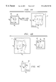
- FIG. 4A illustrates the case when image 42 is re-sized such that the re-sized image xr(n 1 ,n 2 ) 44 is too large for the display window 46 .
- a similar problem occurs if the image is to be used in a desired sub-area of the display window 46 .
- the re-sized image may fit within the overall display area but may be too large for the desired sub-area of the display.
- the original image x(n 1 ,n 2 ) 42 of size N 1 ⁇ N 2 fits within the display window 46 which is of size W 1 ⁇ W 2 .
- Display window 46 can represent either the entire area of a display or a sub-area of the display.
- Re-sized image xr(n 1 ,n 2 ) 44 is an enlarged version of image 42 produced using the Modified ⁇ -Transform Method with scaling factors s 1 and s 2 as disclosed above.
- re-sized image 44 is larger than display window 46 , causing portions of the enlarged image to fall outside of display window 46 .
- FIG. 4B shows cropped image xcr(n 1 ,n 2 ) 48 which comprises a portion of re-sized image 44 , such that the cropped image 48 fits within the display window 46 .
- the cropped image 48 is of size CR 1 ⁇ CR 2 where CR 1 ⁇ N 1 and CR 2 ⁇ N 2 so that cropped image 48 approximates the dimensions of original image 42 .
- re-sized image 44 also may be cropped so that the dimensions, CR 1 1 and CR 2 1 , of cropped image 50 are not equivalent to those of original image 42 .
- cropped image 50 can be of any suitable size for viewing on a sub-portion of the display, such as display window 86 of FIG. 8, which shows a zoomed-in version 84 ′ of image 84 .
- the resized image is larger than the display window, instead of cropping the resized image, it may be desirable to pan the resized image so that sequential portions of the entire resized image may be viewed in the display window.
- resized image 44 can consists of blocks 52 which correspond to discrete spatial regions of resized image 44 .
- Blocks 52 are of dimension B 1 ⁇ B 2 and may be of various sizes, from single pixels to multiple pixel rows and columns.
- FIG. 5B shows display window 46 panning over resized image 44 .
- Display window 46 covers a portion of the blocks 52 of the resized image 44 .
- Blocks 52 which are within display window 46 can be viewed by a user.
- the resized image 44 is panned by sequentially moving blocks 52 across the display window 46 .
- blocks 52 correspond to individual pixels of resized image 44 .
- the image is panned by sequentially adding one row or column of pixels to an edge 54 of display window 46 and removing one row or column of pixels from the opposite edge 56 of display window 46 .
- Resized image 44 can also be panned using multiple pixels.
- multiple rows and columns of pixels may be added and removed at the edges 1 so that the components of the shift vector are:
- m horiz and m vert represent multiple columns and rows of pixels.
- m horiz M 1
- m vert M 2
- Panning can be accomplished using the Modified ⁇ -Transform Method disclosed above.
- the Modified ⁇ -Transform Method is applied to each of those blocks to produce that portion of the resized image 44 .
- a second group of blocks is then identified which corresponds to those blocks which will overlap the display window in the next frame after the display window is moved by the appropriate shift vector.
- the Modified ⁇ -Transform Method is then applied to the second group of blocks to produce a shifted portion of the resized image 44.
- the cropping and panning functions described above will be understood to apply to images which have been resized using scale factors that are greater than, less than or equal to unity.
- the re-sizing, panning and cropping functions may be applied to images in real-time.
- an image may be received by a digital system via an opto-electronic transducing device, such as a video camera, the image may then be compressed using an appropriate MPEG standard.
- the compressed image can then be inverse transformed using a Modified ⁇ -Transform Method to achieve a displayed image which has been resized, zoomed, panned or cropped according to the present invention.
- FIG. 6 illustrates the re-sizing method of the present invention for the case in which the original spatial domain image x(n 1 ,n 2 ) 600 is enlarged by a non-integer scale factor.
- the re-sizing shown in FIG. 6 also includes an example of a re-sizing operation that is combined with a cropping operation to produce the final resized image xcr(n 1 ,n 2 ) 602 .
- Original image 600 is transformed to the transform domain using the Discrete Cosine Transform ⁇ [x(n 1 ,n 2 )] 604 to produce transform domain image X(k 1 ,k 2 ) 606 .
- Transform-domain image 606 is then augmented with synthetic data points DP 608 to create augmented transform image X AUG (k 1 ,k 2 ) 610 .
- Augmented transform image 610 is of size P 1 ⁇ P 2 , where P 1,2 ⁇ s 1,2 N 1,2 .
- the augmented transform image 610 is of size 16 ⁇ 16. This satisfies the requirement P 1,2 ⁇ 12 and may be chosen because fast transforms exist for this size.
- a value of P 1,2 ⁇ 12 may also be selected due to consideration of such factors as the hardware or software used by the system.
- Augmented transform image 610 is then transformed using a Modified ⁇ -Transform Method ⁇ MOD [X AUG (k 1 ,k 2 )] 612 .
- Resized image 614 is of size 16 ⁇ 16 and includes replicated borders 616 and 618 which result from augmented image 610 being larger than size 12 ⁇ 12.
- an excess amount of resized image is created following the Modified ⁇ -Transform Method. This excess image that is contained in borders 616 and 618 can be cropped to give cropped resized image 602 of size 12 ⁇ 12, corresponding to a 1.5 scaling of the original 8 ⁇ 8 image 600 .
- FIG. 7 illustrates the re-sizing method of the present invention for the case in which the original spatial domain image x(n 1 ,n 2 ) 700 is reduced by a non-integer scale factor to create the final cropped and resized image xcr(n 1 ,n 2 ) 702 .
- the scale factor is 3 ⁇ 4.
- Original image 700 is transformed using transform operation ⁇ [x(n 1 ,n 2 )] 704 to give transform image X(k 1 ,k 2 ) 706 . Since this re-sizing is not an enlargement, transform image 706 does not have to be augmented. Instead, the Modified ⁇ -Transform Method ⁇ MOD [X(k 1 ,k 2 )] 708 is applied directly to transform image 706 to give resized image xr(n 1 ,n 2 ) 710 .
- Resized image 710 contains excess image in borders 712 and 714 due to the scaling of the Modified ⁇ -Transform Method 708 .
- cropping resized image 710 to remove excess border 712 and 714 cropped and resized image xcr(n 1 ,n 2 ) 702 is created.
- Image 702 corresponds to a 3 ⁇ 4 scaling of original image 700 .
- FIG. 8 shows a system 80 in which a viewing device 81 , such as a television or personal computer, has a picture 82 with a plurality of images 801 , 802 and 803 .
- a user (not shown) using a remote control 83 or other device, such as a computer mouse, can select a particular image for further zooming.
- portion 84 of image 82 is selected by adjusting outline 85 .
- This selected image can then be displayed on the screen in place of image 82 or, optionally, in a separate window 86 .
- the image displayed in window 86 can then be resized or zoomed in or out.
- the viewer could also elect to pan the image of screen 82 (or of screen 86 ) either row-by-row, column-by-column, block-by-block or in a combination of these.
Abstract
Description


Claims (15)
Priority Applications (6)
| Application Number | Priority Date | Filing Date | Title |
|---|---|---|---|
| US09/154,227 US6456745B1 (en) | 1998-09-16 | 1998-09-16 | Method and apparatus for re-sizing and zooming images by operating directly on their digital transforms |
| CA002347364A CA2347364A1 (en) | 1998-09-16 | 1999-09-15 | A method and apparatus for re-sizing and cropping images by operating directly on their digital orthogonal transforms |
| PCT/US1999/021298 WO2000016263A1 (en) | 1998-09-16 | 1999-09-15 | A method and apparatus for re-sizing and cropping images by operating directly on their digital orthogonal transforms |
| CN99813347A CN1326574A (en) | 1998-09-16 | 1999-09-15 | Method and apparatus for re-sizing and cropping images by operating directly on their digital orthogonal transforms |
| AU61473/99A AU6147399A (en) | 1998-09-16 | 1999-09-15 | A method and apparatus for re-sizing and cropping images by operating directly on their digital orthogonal transforms |
| EP99948258A EP1114399A1 (en) | 1998-09-16 | 1999-09-15 | A method and apparatus for re-sizing and cropping images by operating directly on their digital orthogonal transforms |
Applications Claiming Priority (1)
| Application Number | Priority Date | Filing Date | Title |
|---|---|---|---|
| US09/154,227 US6456745B1 (en) | 1998-09-16 | 1998-09-16 | Method and apparatus for re-sizing and zooming images by operating directly on their digital transforms |
Publications (1)
| Publication Number | Publication Date |
|---|---|
| US6456745B1 true US6456745B1 (en) | 2002-09-24 |
Family
ID=22550526
Family Applications (1)
| Application Number | Title | Priority Date | Filing Date |
|---|---|---|---|
| US09/154,227 Expired - Lifetime US6456745B1 (en) | 1998-09-16 | 1998-09-16 | Method and apparatus for re-sizing and zooming images by operating directly on their digital transforms |
Country Status (6)
| Country | Link |
|---|---|
| US (1) | US6456745B1 (en) |
| EP (1) | EP1114399A1 (en) |
| CN (1) | CN1326574A (en) |
| AU (1) | AU6147399A (en) |
| CA (1) | CA2347364A1 (en) |
| WO (1) | WO2000016263A1 (en) |
Cited By (50)
| Publication number | Priority date | Publication date | Assignee | Title |
|---|---|---|---|---|
| US20020009237A1 (en) * | 2000-07-21 | 2002-01-24 | Tadanori Tezuka | Display reduction method using sub-pixels |
| US20030053717A1 (en) * | 2001-08-28 | 2003-03-20 | Akhan Mehmet Bilgay | Image enhancement and data loss recovery using wavelet transforms |
| US20030174346A1 (en) * | 2002-03-15 | 2003-09-18 | Canon Kabushiki Kaisha | Image processing method and apparatus, and printer driver |
| US6687422B1 (en) * | 2000-02-16 | 2004-02-03 | The Cleveland Clinic Foundation | Discrete image data interpolation using sub-unity shift |
| US20040025112A1 (en) * | 2002-08-01 | 2004-02-05 | Chasen Jeffrey Martin | Method and apparatus for resizing video content displayed within a graphical user interface |
| US20040037355A1 (en) * | 2000-12-07 | 2004-02-26 | Stephane Allie | Coding process and device for the displaying of a zoomed mpeg2 coded image |
| US20040070626A1 (en) * | 2002-09-30 | 2004-04-15 | Canon Kabushiki Kaisha | Image editing method, image editing apparatus, program for implementing image editing method, and recording medium recording program |
| US6807310B1 (en) * | 2000-05-23 | 2004-10-19 | The Board Of Trustees Of The University Of Illinois | Transformation of image parts in different domains to obtain resultant image size different from initial image size |
| US20050058355A1 (en) * | 2000-05-12 | 2005-03-17 | International Business Machines Corporation | Method and apparatus for scaling down of data |
| US20050123194A1 (en) * | 2002-02-21 | 2005-06-09 | Xerox Corporation | Method of embedding color information in printed documents using watermarking |
| US20050162445A1 (en) * | 2004-01-22 | 2005-07-28 | Lumapix | Method and system for interactive cropping of a graphical object within a containing region |
| US20050190982A1 (en) * | 2003-11-28 | 2005-09-01 | Matsushita Electric Industrial Co., Ltd. | Image reducing device and image reducing method |
| US20050254718A1 (en) * | 2002-03-04 | 2005-11-17 | Ryozo Setoguchi | Web-oriented image database building/control method |
| US6970179B1 (en) | 2000-05-12 | 2005-11-29 | International Business Machines Corporation | Method and apparatus for the scaling up of data |
| US20060072853A1 (en) * | 2004-10-05 | 2006-04-06 | Ian Clarke | Method and apparatus for resizing images |
| US20060132836A1 (en) * | 2004-12-21 | 2006-06-22 | Coyne Christopher R | Method and apparatus for re-sizing image data |
| US20060176376A1 (en) * | 2005-02-10 | 2006-08-10 | Dyke Phil V | Apparatus and method for resizing an image |
| US20060193538A1 (en) * | 2005-02-28 | 2006-08-31 | Microsoft Corporation | Graphical user interface system and process for navigating a set of images |
| US20060246880A1 (en) * | 2005-05-02 | 2006-11-02 | Tekelec | Methods, systems, and computer program products for dynamically coordinating collection and distribution of presence information |
| US20070146393A1 (en) * | 2005-12-28 | 2007-06-28 | Xcpt, Inc. | System and method for re-sizing objects |
| US20080181486A1 (en) * | 2007-01-26 | 2008-07-31 | Conversion Works, Inc. | Methodology for 3d scene reconstruction from 2d image sequences |
| US20080225059A1 (en) * | 2007-03-12 | 2008-09-18 | Conversion Works, Inc. | System and method for using off-screen mask space to provide enhanced viewing |
| US20080226160A1 (en) * | 2007-03-12 | 2008-09-18 | Conversion Works, Inc. | Systems and methods for filling light in frames during 2-d to 3-d image conversion |
| US20080226194A1 (en) * | 2007-03-12 | 2008-09-18 | Conversion Works, Inc. | Systems and methods for treating occlusions in 2-d to 3-d image conversion |
| US20080228449A1 (en) * | 2007-03-12 | 2008-09-18 | Conversion Works, Inc. | Systems and methods for 2-d to 3-d conversion using depth access segments to define an object |
| US20080225040A1 (en) * | 2007-03-12 | 2008-09-18 | Conversion Works, Inc. | System and method of treating semi-transparent features in the conversion of two-dimensional images to three-dimensional images |
| US20080226128A1 (en) * | 2007-03-12 | 2008-09-18 | Conversion Works, Inc. | System and method for using feature tracking techniques for the generation of masks in the conversion of two-dimensional images to three-dimensional images |
| US20080226123A1 (en) * | 2007-03-12 | 2008-09-18 | Conversion Works, Inc. | Systems and methods for filling occluded information for 2-d to 3-d conversion |
| US20080225045A1 (en) * | 2007-03-12 | 2008-09-18 | Conversion Works, Inc. | Systems and methods for 2-d to 3-d image conversion using mask to model, or model to mask, conversion |
| US20080226181A1 (en) * | 2007-03-12 | 2008-09-18 | Conversion Works, Inc. | Systems and methods for depth peeling using stereoscopic variables during the rendering of 2-d to 3-d images |
| US20080225042A1 (en) * | 2007-03-12 | 2008-09-18 | Conversion Works, Inc. | Systems and methods for allowing a user to dynamically manipulate stereoscopic parameters |
| US20080246836A1 (en) * | 2004-09-23 | 2008-10-09 | Conversion Works, Inc. | System and method for processing video images for camera recreation |
| US20080259073A1 (en) * | 2004-09-23 | 2008-10-23 | Conversion Works, Inc. | System and method for processing video images |
| US20090224796A1 (en) * | 2008-03-10 | 2009-09-10 | Nicholas Heath | Termination switching based on data rate |
| US20090256903A1 (en) * | 2004-09-23 | 2009-10-15 | Conversion Works, Inc. | System and method for processing video images |
| US20090324092A1 (en) * | 2008-06-27 | 2009-12-31 | Koji Aoyama | Image processing device and image processing method, and program |
| US20100080484A1 (en) * | 2008-09-29 | 2010-04-01 | Keyence Corporation | Image Processing Apparatus, Image Processing Method, and Computer Program |
| US20100289742A1 (en) * | 2006-10-10 | 2010-11-18 | Promethean Limited | Moveable desktop |
| US8090141B2 (en) | 2006-01-31 | 2012-01-03 | Xerox Corporation | System and method to automatically establish preferred area for image-wise watermark |
| US20120038954A1 (en) * | 2010-08-13 | 2012-02-16 | Primax Electronics Ltd. | Image cropping process |
| US8208010B2 (en) | 2004-06-30 | 2012-06-26 | Sony Ericsson Mobile Communications Ab | Face image correction using multiple camera angles |
| US20130106913A1 (en) * | 2011-10-28 | 2013-05-02 | Microsoft Corporation | Image layout for a display |
| US20150054854A1 (en) * | 2013-08-22 | 2015-02-26 | Htc Corporation | Image Cropping Manipulation Method and Portable Electronic Device |
| US20150103101A1 (en) * | 2013-10-10 | 2015-04-16 | Samsung Display Co., Ltd. | Display device and driving method thereof |
| US9371099B2 (en) | 2004-11-03 | 2016-06-21 | The Wilfred J. and Louisette G. Lagassey Irrevocable Trust | Modular intelligent transportation system |
| US20160371815A1 (en) * | 2015-06-17 | 2016-12-22 | Samsung Electronics Co., Ltd. | Electronic device for displaying a plurality of images and method for processing an image |
| US9942487B2 (en) | 2001-01-23 | 2018-04-10 | Visual Effect Innovations, Llc | Systems, apparatus, and methods for creating an eternalism, an appearance of sustained three dimensional motion-direction of unlimited duration, using a finite number of images |
| US9948922B2 (en) | 2001-01-23 | 2018-04-17 | Visual Effect Innovations, Llc | Faster state transitioning for continuous adjustable 3Deeps filter spectacles using multi-layered variable tint materials |
| US10019413B2 (en) * | 2010-10-19 | 2018-07-10 | Apple Inc. | Systems, methods, and computer-readable media for providing a dynamic loupe for displayed information |
| US10742965B2 (en) | 2001-01-23 | 2020-08-11 | Visual Effect Innovations, Llc | Faster state transitioning for continuous adjustable 3Deeps filter spectacles using multi-layered variable tint materials |
Families Citing this family (2)
| Publication number | Priority date | Publication date | Assignee | Title |
|---|---|---|---|---|
| US6954219B2 (en) | 2001-12-12 | 2005-10-11 | Stmicroelectronics, Inc. | Method and system of continuously scaling video images |
| US20060072820A1 (en) | 2004-10-05 | 2006-04-06 | Nokia Corporation | System and method for checking framing and sharpness of a digital image |
Citations (22)
| Publication number | Priority date | Publication date | Assignee | Title |
|---|---|---|---|---|
| US5051927A (en) | 1987-03-03 | 1991-09-24 | Minolta Camera Kabushiki Kaisha | Image editing apparatus for transferring a partial image from one locale to another |
| JPH04239294A (en) * | 1991-01-12 | 1992-08-27 | Sony Corp | Controller for electronic equipment |
| US5168375A (en) | 1991-09-18 | 1992-12-01 | Polaroid Corporation | Image reconstruction by use of discrete cosine and related transforms |
| US5227875A (en) | 1990-08-20 | 1993-07-13 | Kabushiki Kaisha Toshiba | System for transmitting encoded image data with quick image expansion and contraction |
| US5477397A (en) | 1993-02-23 | 1995-12-19 | Matsushita Electric Corporation Of America | Digital high definition television receiver with features that facilitate trick-play modes on a digital VCR |
| US5495292A (en) * | 1993-09-03 | 1996-02-27 | Gte Laboratories Incorporated | Inter-frame wavelet transform coder for color video compression |
| US5519452A (en) * | 1991-10-24 | 1996-05-21 | Eastman Kodak Company | Mechanism for improving television display of still images using image motion-dependent filter |
| US5552824A (en) * | 1993-02-18 | 1996-09-03 | Lynx System Developers, Inc. | Line object scene generation apparatus |
| EP0740269A2 (en) | 1995-04-26 | 1996-10-30 | Hewlett-Packard Company | Scaling compressed images |
| US5574508A (en) * | 1994-11-02 | 1996-11-12 | Rca Thomson Licensing Corporation | Vertical panning for interlaced video |
| US5596346A (en) * | 1994-07-22 | 1997-01-21 | Eastman Kodak Company | Method and apparatus for applying a function to a localized area of a digital image using a window |
| US5604494A (en) * | 1993-09-28 | 1997-02-18 | Sony Corporation | Efficient encoding/decoding apparatus |
| US5619738A (en) * | 1995-05-02 | 1997-04-08 | Eastman Kodak Company | Pre-processing image editing |
| US5649032A (en) * | 1994-11-14 | 1997-07-15 | David Sarnoff Research Center, Inc. | System for automatically aligning images to form a mosaic image |
| US5652849A (en) * | 1995-03-16 | 1997-07-29 | Regents Of The University Of Michigan | Apparatus and method for remote control using a visual information stream |
| WO1997034420A1 (en) | 1996-03-15 | 1997-09-18 | Multimedia Systems Corporation | Interactive cable network providing fax and voice mail |
| US5706216A (en) * | 1995-07-28 | 1998-01-06 | Reisch; Michael L. | System for data compression of an image using a JPEG compression circuit modified for filtering in the frequency domain |
| US5729673A (en) * | 1995-04-07 | 1998-03-17 | Avid Technology, Inc. | Direct manipulation of two-dimensional moving picture streams in three-dimensional space |
| US5774598A (en) * | 1993-11-30 | 1998-06-30 | Polaroid Corporation | System and method for sample rate conversion of an image using discrete cosine transforms |
| US5990890A (en) * | 1997-08-25 | 1999-11-23 | Liberate Technologies | System for data entry and navigation in a user interface |
| US6154762A (en) * | 1998-06-03 | 2000-11-28 | Microsoft Corporation | Fast system and method for computing modulated lapped transforms |
| US6298166B1 (en) * | 1998-03-30 | 2001-10-02 | Seiko Epson Corporation | Image transformations in the compressed domain |
-
1998
- 1998-09-16 US US09/154,227 patent/US6456745B1/en not_active Expired - Lifetime
-
1999
- 1999-09-15 EP EP99948258A patent/EP1114399A1/en not_active Withdrawn
- 1999-09-15 CN CN99813347A patent/CN1326574A/en active Pending
- 1999-09-15 WO PCT/US1999/021298 patent/WO2000016263A1/en not_active Application Discontinuation
- 1999-09-15 AU AU61473/99A patent/AU6147399A/en not_active Abandoned
- 1999-09-15 CA CA002347364A patent/CA2347364A1/en not_active Abandoned
Patent Citations (22)
| Publication number | Priority date | Publication date | Assignee | Title |
|---|---|---|---|---|
| US5051927A (en) | 1987-03-03 | 1991-09-24 | Minolta Camera Kabushiki Kaisha | Image editing apparatus for transferring a partial image from one locale to another |
| US5227875A (en) | 1990-08-20 | 1993-07-13 | Kabushiki Kaisha Toshiba | System for transmitting encoded image data with quick image expansion and contraction |
| JPH04239294A (en) * | 1991-01-12 | 1992-08-27 | Sony Corp | Controller for electronic equipment |
| US5168375A (en) | 1991-09-18 | 1992-12-01 | Polaroid Corporation | Image reconstruction by use of discrete cosine and related transforms |
| US5519452A (en) * | 1991-10-24 | 1996-05-21 | Eastman Kodak Company | Mechanism for improving television display of still images using image motion-dependent filter |
| US5552824A (en) * | 1993-02-18 | 1996-09-03 | Lynx System Developers, Inc. | Line object scene generation apparatus |
| US5477397A (en) | 1993-02-23 | 1995-12-19 | Matsushita Electric Corporation Of America | Digital high definition television receiver with features that facilitate trick-play modes on a digital VCR |
| US5495292A (en) * | 1993-09-03 | 1996-02-27 | Gte Laboratories Incorporated | Inter-frame wavelet transform coder for color video compression |
| US5604494A (en) * | 1993-09-28 | 1997-02-18 | Sony Corporation | Efficient encoding/decoding apparatus |
| US5774598A (en) * | 1993-11-30 | 1998-06-30 | Polaroid Corporation | System and method for sample rate conversion of an image using discrete cosine transforms |
| US5596346A (en) * | 1994-07-22 | 1997-01-21 | Eastman Kodak Company | Method and apparatus for applying a function to a localized area of a digital image using a window |
| US5574508A (en) * | 1994-11-02 | 1996-11-12 | Rca Thomson Licensing Corporation | Vertical panning for interlaced video |
| US5649032A (en) * | 1994-11-14 | 1997-07-15 | David Sarnoff Research Center, Inc. | System for automatically aligning images to form a mosaic image |
| US5652849A (en) * | 1995-03-16 | 1997-07-29 | Regents Of The University Of Michigan | Apparatus and method for remote control using a visual information stream |
| US5729673A (en) * | 1995-04-07 | 1998-03-17 | Avid Technology, Inc. | Direct manipulation of two-dimensional moving picture streams in three-dimensional space |
| EP0740269A2 (en) | 1995-04-26 | 1996-10-30 | Hewlett-Packard Company | Scaling compressed images |
| US5619738A (en) * | 1995-05-02 | 1997-04-08 | Eastman Kodak Company | Pre-processing image editing |
| US5706216A (en) * | 1995-07-28 | 1998-01-06 | Reisch; Michael L. | System for data compression of an image using a JPEG compression circuit modified for filtering in the frequency domain |
| WO1997034420A1 (en) | 1996-03-15 | 1997-09-18 | Multimedia Systems Corporation | Interactive cable network providing fax and voice mail |
| US5990890A (en) * | 1997-08-25 | 1999-11-23 | Liberate Technologies | System for data entry and navigation in a user interface |
| US6298166B1 (en) * | 1998-03-30 | 2001-10-02 | Seiko Epson Corporation | Image transformations in the compressed domain |
| US6154762A (en) * | 1998-06-03 | 2000-11-28 | Microsoft Corporation | Fast system and method for computing modulated lapped transforms |
Non-Patent Citations (5)
| Title |
|---|
| "Adaptive Motion Vector Resampling for Compressed Video Down-Scaling", by Bo Shen, et al.; IEEE; Jul. 1997; pp. 771-774. |
| "Circuits and Systems Letters", by P. Sathyanarayana, et al.; IEEE Transactions on Circuits and Systems, vol. 37, No. 5; May 1990; pp. 623-625. |
| "Manipulation and Compositing of MC-DCT Compressed Video", IEEE Journal on Selected Areas in Communications, US, IEEE Inc., New York, vol. 13, No. 1, pp. 1-11 XP000492740. |
| "Video Post-Production with Compressed Images", SMPTE Journal, US, SMPTE Inc., Scarsdale, New York, vol. 103, No. 2, pp. 76-84 XP000429905. |
| International Search Report, PCT/US99/21298. |
Cited By (91)
| Publication number | Priority date | Publication date | Assignee | Title |
|---|---|---|---|---|
| US6687422B1 (en) * | 2000-02-16 | 2004-02-03 | The Cleveland Clinic Foundation | Discrete image data interpolation using sub-unity shift |
| US7903889B2 (en) | 2000-05-12 | 2011-03-08 | International Business Machines Corporation | System and computer readable medium for the scaling down of data |
| US20080212885A1 (en) * | 2000-05-12 | 2008-09-04 | International Business Machines Corporation | Scaling down of data |
| US7373003B2 (en) * | 2000-05-12 | 2008-05-13 | International Business Machines Corporation | Method for the scaling down of data |
| US7463777B2 (en) * | 2000-05-12 | 2008-12-09 | International Business Machines Corporation | Method for the scaling down of data |
| US20090060358A1 (en) * | 2000-05-12 | 2009-03-05 | International Business Machines Corporation | System and computer readable medium for the scaling down of data |
| US7720310B2 (en) | 2000-05-12 | 2010-05-18 | International Business Machines Corporation | Scaling down of data |
| US7062098B1 (en) * | 2000-05-12 | 2006-06-13 | International Business Machines Corporation | Method and apparatus for the scaling down of data |
| US20050058355A1 (en) * | 2000-05-12 | 2005-03-17 | International Business Machines Corporation | Method and apparatus for scaling down of data |
| US20050117809A1 (en) * | 2000-05-12 | 2005-06-02 | International Business Machines Corporation | Method and apparatus for scaling down of data |
| US6970179B1 (en) | 2000-05-12 | 2005-11-29 | International Business Machines Corporation | Method and apparatus for the scaling up of data |
| US6807310B1 (en) * | 2000-05-23 | 2004-10-19 | The Board Of Trustees Of The University Of Illinois | Transformation of image parts in different domains to obtain resultant image size different from initial image size |
| US20020009237A1 (en) * | 2000-07-21 | 2002-01-24 | Tadanori Tezuka | Display reduction method using sub-pixels |
| US20040037355A1 (en) * | 2000-12-07 | 2004-02-26 | Stephane Allie | Coding process and device for the displaying of a zoomed mpeg2 coded image |
| US7352810B2 (en) * | 2000-12-07 | 2008-04-01 | Thomson Licensing | Coding process and device for the displaying of a zoomed MPEG2 coded image |
| US10742965B2 (en) | 2001-01-23 | 2020-08-11 | Visual Effect Innovations, Llc | Faster state transitioning for continuous adjustable 3Deeps filter spectacles using multi-layered variable tint materials |
| US9948922B2 (en) | 2001-01-23 | 2018-04-17 | Visual Effect Innovations, Llc | Faster state transitioning for continuous adjustable 3Deeps filter spectacles using multi-layered variable tint materials |
| US10021380B1 (en) | 2001-01-23 | 2018-07-10 | Visual Effect Innovations, Llc | Faster state transitioning for continuous adjustable 3Deeps filter spectacles using multi-layered variable tint materials |
| US9942487B2 (en) | 2001-01-23 | 2018-04-10 | Visual Effect Innovations, Llc | Systems, apparatus, and methods for creating an eternalism, an appearance of sustained three dimensional motion-direction of unlimited duration, using a finite number of images |
| US7085436B2 (en) * | 2001-08-28 | 2006-08-01 | Visioprime | Image enhancement and data loss recovery using wavelet transforms |
| US20030053717A1 (en) * | 2001-08-28 | 2003-03-20 | Akhan Mehmet Bilgay | Image enhancement and data loss recovery using wavelet transforms |
| US20050123194A1 (en) * | 2002-02-21 | 2005-06-09 | Xerox Corporation | Method of embedding color information in printed documents using watermarking |
| US7515732B2 (en) * | 2002-02-21 | 2009-04-07 | Xerox Corporation | Method of embedding color information in printed documents using watermarking |
| US20050254718A1 (en) * | 2002-03-04 | 2005-11-17 | Ryozo Setoguchi | Web-oriented image database building/control method |
| US7995219B2 (en) * | 2002-03-15 | 2011-08-09 | Canon Kabushiki Kaisha | Image processing method and apparatus, and printer driver |
| US20030174346A1 (en) * | 2002-03-15 | 2003-09-18 | Canon Kabushiki Kaisha | Image processing method and apparatus, and printer driver |
| US7549127B2 (en) * | 2002-08-01 | 2009-06-16 | Realnetworks, Inc. | Method and apparatus for resizing video content displayed within a graphical user interface |
| US20040025112A1 (en) * | 2002-08-01 | 2004-02-05 | Chasen Jeffrey Martin | Method and apparatus for resizing video content displayed within a graphical user interface |
| US8112712B2 (en) | 2002-09-30 | 2012-02-07 | Canon Kabushiki Kaisha | Image editing method, image editing apparatus, program for implementing image editing method, and recording medium recording program |
| US7454707B2 (en) * | 2002-09-30 | 2008-11-18 | Canon Kabushiki Kaisha | Image editing method, image editing apparatus, program for implementing image editing method, and recording medium recording program |
| US20040070626A1 (en) * | 2002-09-30 | 2004-04-15 | Canon Kabushiki Kaisha | Image editing method, image editing apparatus, program for implementing image editing method, and recording medium recording program |
| US9135733B2 (en) | 2002-09-30 | 2015-09-15 | Canon Kabushiki Kaisha | Image editing method, image editing apparatus, program for implementing image editing method, and recording medium recording program |
| US20080295023A1 (en) * | 2002-09-30 | 2008-11-27 | Canon Kabushiki Kaisha | Image editing method, image editing apparatus, program for implementing image editing method, and recording medium recording program |
| US20050190982A1 (en) * | 2003-11-28 | 2005-09-01 | Matsushita Electric Industrial Co., Ltd. | Image reducing device and image reducing method |
| US20050162445A1 (en) * | 2004-01-22 | 2005-07-28 | Lumapix | Method and system for interactive cropping of a graphical object within a containing region |
| US8208010B2 (en) | 2004-06-30 | 2012-06-26 | Sony Ericsson Mobile Communications Ab | Face image correction using multiple camera angles |
| US20110169827A1 (en) * | 2004-09-23 | 2011-07-14 | Conversion Works, Inc. | System and method for processing video images |
| US20080246836A1 (en) * | 2004-09-23 | 2008-10-09 | Conversion Works, Inc. | System and method for processing video images for camera recreation |
| US20080259073A1 (en) * | 2004-09-23 | 2008-10-23 | Conversion Works, Inc. | System and method for processing video images |
| US8217931B2 (en) | 2004-09-23 | 2012-07-10 | Conversion Works, Inc. | System and method for processing video images |
| US8860712B2 (en) | 2004-09-23 | 2014-10-14 | Intellectual Discovery Co., Ltd. | System and method for processing video images |
| US20090256903A1 (en) * | 2004-09-23 | 2009-10-15 | Conversion Works, Inc. | System and method for processing video images |
| US20060072853A1 (en) * | 2004-10-05 | 2006-04-06 | Ian Clarke | Method and apparatus for resizing images |
| US7574071B2 (en) * | 2004-10-05 | 2009-08-11 | Seiko Epson Corporation | Method and apparatus for resizing images |
| US10979959B2 (en) | 2004-11-03 | 2021-04-13 | The Wilfred J. and Louisette G. Lagassey Irrevocable Trust | Modular intelligent transportation system |
| US9371099B2 (en) | 2004-11-03 | 2016-06-21 | The Wilfred J. and Louisette G. Lagassey Irrevocable Trust | Modular intelligent transportation system |
| US20060132836A1 (en) * | 2004-12-21 | 2006-06-22 | Coyne Christopher R | Method and apparatus for re-sizing image data |
| US20060176376A1 (en) * | 2005-02-10 | 2006-08-10 | Dyke Phil V | Apparatus and method for resizing an image |
| US7733405B2 (en) * | 2005-02-10 | 2010-06-08 | Seiko Epson Corporation | Apparatus and method for resizing an image |
| US20060193538A1 (en) * | 2005-02-28 | 2006-08-31 | Microsoft Corporation | Graphical user interface system and process for navigating a set of images |
| US7737995B2 (en) * | 2005-02-28 | 2010-06-15 | Microsoft Corporation | Graphical user interface system and process for navigating a set of images |
| US20060246880A1 (en) * | 2005-05-02 | 2006-11-02 | Tekelec | Methods, systems, and computer program products for dynamically coordinating collection and distribution of presence information |
| US20070146393A1 (en) * | 2005-12-28 | 2007-06-28 | Xcpt, Inc. | System and method for re-sizing objects |
| US8090141B2 (en) | 2006-01-31 | 2012-01-03 | Xerox Corporation | System and method to automatically establish preferred area for image-wise watermark |
| US20100289742A1 (en) * | 2006-10-10 | 2010-11-18 | Promethean Limited | Moveable desktop |
| US8115734B2 (en) * | 2006-10-10 | 2012-02-14 | Promethean Ltd. | Moveable desktop |
| US20080181486A1 (en) * | 2007-01-26 | 2008-07-31 | Conversion Works, Inc. | Methodology for 3d scene reconstruction from 2d image sequences |
| US8655052B2 (en) | 2007-01-26 | 2014-02-18 | Intellectual Discovery Co., Ltd. | Methodology for 3D scene reconstruction from 2D image sequences |
| US20080228449A1 (en) * | 2007-03-12 | 2008-09-18 | Conversion Works, Inc. | Systems and methods for 2-d to 3-d conversion using depth access segments to define an object |
| US20080226181A1 (en) * | 2007-03-12 | 2008-09-18 | Conversion Works, Inc. | Systems and methods for depth peeling using stereoscopic variables during the rendering of 2-d to 3-d images |
| US20110227917A1 (en) * | 2007-03-12 | 2011-09-22 | Conversion Works, Inc. | System and method for using off-screen mask space to provide enhanced viewing |
| US20080225040A1 (en) * | 2007-03-12 | 2008-09-18 | Conversion Works, Inc. | System and method of treating semi-transparent features in the conversion of two-dimensional images to three-dimensional images |
| US20080225045A1 (en) * | 2007-03-12 | 2008-09-18 | Conversion Works, Inc. | Systems and methods for 2-d to 3-d image conversion using mask to model, or model to mask, conversion |
| US20080226123A1 (en) * | 2007-03-12 | 2008-09-18 | Conversion Works, Inc. | Systems and methods for filling occluded information for 2-d to 3-d conversion |
| US9082224B2 (en) | 2007-03-12 | 2015-07-14 | Intellectual Discovery Co., Ltd. | Systems and methods 2-D to 3-D conversion using depth access segiments to define an object |
| US8274530B2 (en) | 2007-03-12 | 2012-09-25 | Conversion Works, Inc. | Systems and methods for filling occluded information for 2-D to 3-D conversion |
| US20080226194A1 (en) * | 2007-03-12 | 2008-09-18 | Conversion Works, Inc. | Systems and methods for treating occlusions in 2-d to 3-d image conversion |
| US20080226160A1 (en) * | 2007-03-12 | 2008-09-18 | Conversion Works, Inc. | Systems and methods for filling light in frames during 2-d to 3-d image conversion |
| US20080225059A1 (en) * | 2007-03-12 | 2008-09-18 | Conversion Works, Inc. | System and method for using off-screen mask space to provide enhanced viewing |
| US20080225042A1 (en) * | 2007-03-12 | 2008-09-18 | Conversion Works, Inc. | Systems and methods for allowing a user to dynamically manipulate stereoscopic parameters |
| US8791941B2 (en) | 2007-03-12 | 2014-07-29 | Intellectual Discovery Co., Ltd. | Systems and methods for 2-D to 3-D image conversion using mask to model, or model to mask, conversion |
| US20080226128A1 (en) * | 2007-03-12 | 2008-09-18 | Conversion Works, Inc. | System and method for using feature tracking techniques for the generation of masks in the conversion of two-dimensional images to three-dimensional images |
| US8878835B2 (en) | 2007-03-12 | 2014-11-04 | Intellectual Discovery Co., Ltd. | System and method for using feature tracking techniques for the generation of masks in the conversion of two-dimensional images to three-dimensional images |
| US20090224796A1 (en) * | 2008-03-10 | 2009-09-10 | Nicholas Heath | Termination switching based on data rate |
| US8224124B2 (en) * | 2008-06-27 | 2012-07-17 | Sony Corporation | Image processing device and image processing method, and program |
| US20090324092A1 (en) * | 2008-06-27 | 2009-12-31 | Koji Aoyama | Image processing device and image processing method, and program |
| US20100080484A1 (en) * | 2008-09-29 | 2010-04-01 | Keyence Corporation | Image Processing Apparatus, Image Processing Method, and Computer Program |
| US8295645B2 (en) * | 2008-09-29 | 2012-10-23 | Keyence Corporation | Image processing apparatus, image processing method, and computer program |
| US8368965B2 (en) * | 2010-08-13 | 2013-02-05 | Primax Electronics Ltd. | Image cropping process |
| US20120038954A1 (en) * | 2010-08-13 | 2012-02-16 | Primax Electronics Ltd. | Image cropping process |
| US10019413B2 (en) * | 2010-10-19 | 2018-07-10 | Apple Inc. | Systems, methods, and computer-readable media for providing a dynamic loupe for displayed information |
| US10984169B2 (en) | 2010-10-19 | 2021-04-20 | Apple Inc. | Systems, methods, and computer-readable media for providing a dynamic loupe for displayed information |
| US9269323B2 (en) * | 2011-10-28 | 2016-02-23 | Microsoft Technology Licensing, Llc | Image layout for a display |
| US20130106913A1 (en) * | 2011-10-28 | 2013-05-02 | Microsoft Corporation | Image layout for a display |
| US9424808B2 (en) * | 2013-08-22 | 2016-08-23 | Htc Corporation | Image cropping manipulation method and portable electronic device |
| CN104423877A (en) * | 2013-08-22 | 2015-03-18 | 宏达国际电子股份有限公司 | Image Cropping Manipulation Method and Portable Electronic Device |
| CN104423877B (en) * | 2013-08-22 | 2018-04-24 | 宏达国际电子股份有限公司 | Image method of cutting out and its portable electron device |
| US20150054854A1 (en) * | 2013-08-22 | 2015-02-26 | Htc Corporation | Image Cropping Manipulation Method and Portable Electronic Device |
| US20150103101A1 (en) * | 2013-10-10 | 2015-04-16 | Samsung Display Co., Ltd. | Display device and driving method thereof |
| US20160371815A1 (en) * | 2015-06-17 | 2016-12-22 | Samsung Electronics Co., Ltd. | Electronic device for displaying a plurality of images and method for processing an image |
| US10210598B2 (en) * | 2015-06-17 | 2019-02-19 | Samsung Electronics Co., Ltd. | Electronic device for displaying a plurality of images and method for processing an image |
Also Published As
| Publication number | Publication date |
|---|---|
| EP1114399A1 (en) | 2001-07-11 |
| AU6147399A (en) | 2000-04-03 |
| CN1326574A (en) | 2001-12-12 |
| CA2347364A1 (en) | 2000-03-23 |
| WO2000016263A1 (en) | 2000-03-23 |
Similar Documents
| Publication | Publication Date | Title |
|---|---|---|
| US6456745B1 (en) | Method and apparatus for re-sizing and zooming images by operating directly on their digital transforms | |
| US6151420A (en) | Minimizing blocking artifacts in a filtered image | |
| US6873343B2 (en) | Scalable graphics image drawings on multiresolution image with/without image data re-usage | |
| US5717789A (en) | Image enhancement by non-linear extrapolation in frequency space | |
| US6005983A (en) | Image enhancement by non-linear extrapolation in frequency space | |
| US7206451B2 (en) | Multi-resolution image data management system and method based on tiled wavelet-like transform and distinct bitstreams for distinct groups of bit planes | |
| USRE47337E1 (en) | Filtering control method for improving image quality of bi-linear interpolated image | |
| US5703965A (en) | Image compression/decompression based on mathematical transform, reduction/expansion, and image sharpening | |
| US20020145610A1 (en) | Video processing engine overlay filter scaler | |
| US20020021758A1 (en) | System and method for efficient transmission and display of image details by re-usage of compressed data | |
| KR19990064158A (en) | Method and apparatus for resizing an image using discrete cosine transform | |
| EP0781052A2 (en) | Universal MPEG decoder with scalable picture size | |
| TW409210B (en) | Continuous tone compression/decompression apparatus and method, data process apparatus and device, and memory media for storing the programs executing these methods | |
| JPH0326600B2 (en) | ||
| EP1027662A1 (en) | Image noise reduction system using a dct pyramid | |
| US20120087582A1 (en) | Method and system for resizing an image | |
| US5280343A (en) | Separable subsampling of digital image data with general periodic symmetry | |
| US5483474A (en) | D-dimensional, fractional bandwidth signal processing apparatus | |
| WO2001069585A1 (en) | System and method for efficient transmission and display of image details by re-usage of compressed data | |
| JP3403724B2 (en) | Image reproducing apparatus and method | |
| Mukherjee et al. | Resizing color images in the compressed domain | |
| JP3750164B2 (en) | Image processing method and image processing apparatus | |
| JPH07160865A (en) | Still picture reproducing device | |
| KR101402630B1 (en) | Image interpolation method | |
| EP2544145B1 (en) | Method, arrangement, computer programm and computer-readable storage medium for scaling two-dimensional structures |
Legal Events
| Date | Code | Title | Description |
|---|---|---|---|
| AS | Assignment |
Owner name: PUSH ENTERTAINMENT INC., CANADA Free format text: ASSIGNMENT OF ASSIGNORS INTEREST;ASSIGNORS:BRUTON, LEONARD THOMAS;SIMPSON, TODD;YEE, BARRY;REEL/FRAME:009622/0709 Effective date: 19981106 |
|
| STCF | Information on status: patent grant |
Free format text: PATENTED CASE |
|
| CC | Certificate of correction | ||
| AS | Assignment |
Owner name: HEADPLAY, INC., CANADA Free format text: CHANGE OF NAME;ASSIGNOR:PUSH ENTERTAINMENT INC.;REEL/FRAME:016153/0587 Effective date: 20031230 Owner name: CONVERSIN WORKS, INC., ALBERTA Free format text: ASSIGNMENT OF ASSIGNORS INTEREST;ASSIGNOR:HEADPLAY, INC.;REEL/FRAME:016153/0640 Effective date: 20040816 |
|
| FPAY | Fee payment |
Year of fee payment: 4 |
|
| FPAY | Fee payment |
Year of fee payment: 8 |
|
| AS | Assignment |
Owner name: WORLDPLAY (BARBADOS) INC., BARBADOS Free format text: ASSIGNMENT OF ASSIGNORS INTEREST;ASSIGNOR:CONVERSION WORKS, INC.;REEL/FRAME:025126/0605 Effective date: 20100811 |
|
| AS | Assignment |
Owner name: CONVERSION WORKS, INC., CANADA Free format text: ASSIGNMENT OF ASSIGNORS INTEREST;ASSIGNOR:WORLDPLAY (BARBADOS) INC.;REEL/FRAME:029327/0750 Effective date: 20121119 |
|
| FEPP | Fee payment procedure |
Free format text: PAYOR NUMBER ASSIGNED (ORIGINAL EVENT CODE: ASPN); ENTITY STATUS OF PATENT OWNER: SMALL ENTITY |
|
| AS | Assignment |
Owner name: INTELLECTUAL DISCOVERY CO., LTD., KOREA, REPUBLIC Free format text: ASSIGNMENT OF ASSIGNORS INTEREST;ASSIGNOR:CONVERSION WORKS, INC.;REEL/FRAME:029772/0078 Effective date: 20121220 |
|
| FEPP | Fee payment procedure |
Free format text: PAYER NUMBER DE-ASSIGNED (ORIGINAL EVENT CODE: RMPN); ENTITY STATUS OF PATENT OWNER: SMALL ENTITY Free format text: PAYOR NUMBER ASSIGNED (ORIGINAL EVENT CODE: ASPN); ENTITY STATUS OF PATENT OWNER: SMALL ENTITY |
|
| FPAY | Fee payment |
Year of fee payment: 12 |