US6468709B2 - Biaxially oriented image element with sharpening agent - Google Patents
Biaxially oriented image element with sharpening agent Download PDFInfo
- Publication number
- US6468709B2 US6468709B2 US09/904,682 US90468201A US6468709B2 US 6468709 B2 US6468709 B2 US 6468709B2 US 90468201 A US90468201 A US 90468201A US 6468709 B2 US6468709 B2 US 6468709B2
- Authority
- US
- United States
- Prior art keywords
- layer
- sheet
- photographic
- silver halide
- biaxially oriented
- Prior art date
- Legal status (The legal status is an assumption and is not a legal conclusion. Google has not performed a legal analysis and makes no representation as to the accuracy of the status listed.)
- Expired - Fee Related
Links
- 239000000463 material Substances 0.000 claims abstract description 66
- 230000002708 enhancing effect Effects 0.000 claims abstract description 27
- 238000003384 imaging method Methods 0.000 claims description 55
- 229920000642 polymer Polymers 0.000 claims description 55
- 229920000098 polyolefin Polymers 0.000 claims description 24
- 239000002245 particle Substances 0.000 claims description 22
- 229920000728 polyester Polymers 0.000 claims description 16
- 239000011324 bead Substances 0.000 claims description 9
- 239000011521 glass Substances 0.000 claims description 7
- -1 silver halide Chemical class 0.000 abstract description 245
- 229910052709 silver Inorganic materials 0.000 abstract description 100
- 239000004332 silver Substances 0.000 abstract description 100
- 239000003795 chemical substances by application Substances 0.000 abstract description 62
- 239000010410 layer Substances 0.000 description 161
- 239000000839 emulsion Substances 0.000 description 76
- GWEVSGVZZGPLCZ-UHFFFAOYSA-N Titan oxide Chemical compound O=[Ti]=O GWEVSGVZZGPLCZ-UHFFFAOYSA-N 0.000 description 53
- 239000002585 base Substances 0.000 description 44
- 239000003446 ligand Substances 0.000 description 43
- 239000002019 doping agent Substances 0.000 description 42
- 238000000034 method Methods 0.000 description 42
- 239000000123 paper Substances 0.000 description 37
- 125000001424 substituent group Chemical group 0.000 description 37
- 239000000975 dye Substances 0.000 description 34
- BQCADISMDOOEFD-UHFFFAOYSA-N Silver Chemical compound [Ag] BQCADISMDOOEFD-UHFFFAOYSA-N 0.000 description 33
- 125000004432 carbon atom Chemical group C* 0.000 description 29
- VEXZGXHMUGYJMC-UHFFFAOYSA-M Chloride anion Chemical compound [Cl-] VEXZGXHMUGYJMC-UHFFFAOYSA-M 0.000 description 25
- 125000000217 alkyl group Chemical group 0.000 description 25
- 239000000203 mixture Substances 0.000 description 21
- 230000008569 process Effects 0.000 description 21
- 125000003118 aryl group Chemical group 0.000 description 20
- 108010010803 Gelatin Proteins 0.000 description 19
- 239000004743 Polypropylene Substances 0.000 description 19
- 229920000159 gelatin Polymers 0.000 description 19
- 239000008273 gelatin Substances 0.000 description 19
- 235000019322 gelatine Nutrition 0.000 description 19
- 235000011852 gelatine desserts Nutrition 0.000 description 19
- 229920001155 polypropylene Polymers 0.000 description 19
- 239000002131 composite material Substances 0.000 description 17
- 230000006872 improvement Effects 0.000 description 17
- 239000001257 hydrogen Substances 0.000 description 15
- 229910052739 hydrogen Inorganic materials 0.000 description 15
- 125000004435 hydrogen atom Chemical group [H]* 0.000 description 15
- 238000007639 printing Methods 0.000 description 15
- 239000011159 matrix material Substances 0.000 description 14
- 239000007787 solid Substances 0.000 description 14
- 230000003746 surface roughness Effects 0.000 description 14
- 239000004698 Polyethylene Substances 0.000 description 13
- 125000003545 alkoxy group Chemical group 0.000 description 13
- 239000013078 crystal Substances 0.000 description 13
- 125000000623 heterocyclic group Chemical group 0.000 description 13
- 229920000573 polyethylene Polymers 0.000 description 13
- 230000005855 radiation Effects 0.000 description 13
- 239000003963 antioxidant agent Substances 0.000 description 12
- 235000006708 antioxidants Nutrition 0.000 description 12
- TZCXTZWJZNENPQ-UHFFFAOYSA-L barium sulfate Chemical compound [Ba+2].[O-]S([O-])(=O)=O TZCXTZWJZNENPQ-UHFFFAOYSA-L 0.000 description 12
- 230000008901 benefit Effects 0.000 description 11
- 238000000576 coating method Methods 0.000 description 11
- 238000001125 extrusion Methods 0.000 description 11
- XMBWDFGMSWQBCA-UHFFFAOYSA-N hydrogen iodide Chemical compound I XMBWDFGMSWQBCA-UHFFFAOYSA-N 0.000 description 11
- 239000000243 solution Substances 0.000 description 11
- LYCAIKOWRPUZTN-UHFFFAOYSA-N Ethylene glycol Chemical compound OCCO LYCAIKOWRPUZTN-UHFFFAOYSA-N 0.000 description 10
- FZWLAAWBMGSTSO-UHFFFAOYSA-N Thiazole Chemical compound C1=CSC=N1 FZWLAAWBMGSTSO-UHFFFAOYSA-N 0.000 description 10
- 230000000694 effects Effects 0.000 description 10
- 125000004093 cyano group Chemical group *C#N 0.000 description 9
- 229910052736 halogen Inorganic materials 0.000 description 9
- 229910052741 iridium Inorganic materials 0.000 description 9
- 230000003287 optical effect Effects 0.000 description 9
- 238000011160 research Methods 0.000 description 9
- 239000012463 white pigment Substances 0.000 description 9
- RLYUNPNLXMSXAX-UHFFFAOYSA-N 5-methylthiazole Chemical compound CC1=CN=CS1 RLYUNPNLXMSXAX-UHFFFAOYSA-N 0.000 description 8
- VTYYLEPIZMXCLO-UHFFFAOYSA-L Calcium carbonate Chemical compound [Ca+2].[O-]C([O-])=O VTYYLEPIZMXCLO-UHFFFAOYSA-L 0.000 description 8
- VYPSYNLAJGMNEJ-UHFFFAOYSA-N Silicium dioxide Chemical compound O=[Si]=O VYPSYNLAJGMNEJ-UHFFFAOYSA-N 0.000 description 8
- FAPWRFPIFSIZLT-UHFFFAOYSA-M Sodium chloride Chemical compound [Na+].[Cl-] FAPWRFPIFSIZLT-UHFFFAOYSA-M 0.000 description 8
- 125000004104 aryloxy group Chemical group 0.000 description 8
- 230000015572 biosynthetic process Effects 0.000 description 8
- 229910052799 carbon Inorganic materials 0.000 description 8
- 238000006243 chemical reaction Methods 0.000 description 8
- 229920001577 copolymer Chemical group 0.000 description 8
- 239000011229 interlayer Substances 0.000 description 8
- 238000001556 precipitation Methods 0.000 description 8
- 229940100484 5-chloro-2-methyl-4-isothiazolin-3-one Drugs 0.000 description 7
- XEEYBQQBJWHFJM-UHFFFAOYSA-N Iron Chemical compound [Fe] XEEYBQQBJWHFJM-UHFFFAOYSA-N 0.000 description 7
- DHNRXBZYEKSXIM-UHFFFAOYSA-N chloromethylisothiazolinone Chemical compound CN1SC(Cl)=CC1=O DHNRXBZYEKSXIM-UHFFFAOYSA-N 0.000 description 7
- 239000011248 coating agent Substances 0.000 description 7
- 150000002367 halogens Chemical class 0.000 description 7
- 239000000126 substance Substances 0.000 description 7
- 238000012546 transfer Methods 0.000 description 7
- MYRTYDVEIRVNKP-UHFFFAOYSA-N 1,2-Divinylbenzene Chemical compound C=CC1=CC=CC=C1C=C MYRTYDVEIRVNKP-UHFFFAOYSA-N 0.000 description 6
- WEVYAHXRMPXWCK-UHFFFAOYSA-N Acetonitrile Chemical compound CC#N WEVYAHXRMPXWCK-UHFFFAOYSA-N 0.000 description 6
- CPELXLSAUQHCOX-UHFFFAOYSA-M Bromide Chemical compound [Br-] CPELXLSAUQHCOX-UHFFFAOYSA-M 0.000 description 6
- FFEARJCKVFRZRR-BYPYZUCNSA-N L-methionine Chemical compound CSCC[C@H](N)C(O)=O FFEARJCKVFRZRR-BYPYZUCNSA-N 0.000 description 6
- ZLMJMSJWJFRBEC-UHFFFAOYSA-N Potassium Chemical compound [K] ZLMJMSJWJFRBEC-UHFFFAOYSA-N 0.000 description 6
- 239000000853 adhesive Substances 0.000 description 6
- 230000001070 adhesive effect Effects 0.000 description 6
- 125000004453 alkoxycarbonyl group Chemical group 0.000 description 6
- 125000000129 anionic group Chemical group 0.000 description 6
- 229920002678 cellulose Polymers 0.000 description 6
- 239000001913 cellulose Substances 0.000 description 6
- 125000001309 chloro group Chemical group Cl* 0.000 description 6
- 239000000835 fiber Substances 0.000 description 6
- 125000002887 hydroxy group Chemical group [H]O* 0.000 description 6
- GKOZUEZYRPOHIO-UHFFFAOYSA-N iridium atom Chemical compound [Ir] GKOZUEZYRPOHIO-UHFFFAOYSA-N 0.000 description 6
- 239000007788 liquid Substances 0.000 description 6
- 229930182817 methionine Natural products 0.000 description 6
- IJGRMHOSHXDMSA-UHFFFAOYSA-N nitrogen Substances N#N IJGRMHOSHXDMSA-UHFFFAOYSA-N 0.000 description 6
- 229910052760 oxygen Inorganic materials 0.000 description 6
- 239000000049 pigment Substances 0.000 description 6
- 229910052700 potassium Inorganic materials 0.000 description 6
- 239000011591 potassium Substances 0.000 description 6
- SQGYOTSLMSWVJD-UHFFFAOYSA-N silver(1+) nitrate Chemical compound [Ag+].[O-]N(=O)=O SQGYOTSLMSWVJD-UHFFFAOYSA-N 0.000 description 6
- 230000003595 spectral effect Effects 0.000 description 6
- 150000003557 thiazoles Chemical class 0.000 description 6
- VGGSQFUCUMXWEO-UHFFFAOYSA-N Ethene Chemical compound C=C VGGSQFUCUMXWEO-UHFFFAOYSA-N 0.000 description 5
- 239000005977 Ethylene Substances 0.000 description 5
- UFHFLCQGNIYNRP-UHFFFAOYSA-N Hydrogen Chemical compound [H][H] UFHFLCQGNIYNRP-UHFFFAOYSA-N 0.000 description 5
- 206010070834 Sensitisation Diseases 0.000 description 5
- 239000000654 additive Substances 0.000 description 5
- QVGXLLKOCUKJST-UHFFFAOYSA-N atomic oxygen Chemical group [O] QVGXLLKOCUKJST-UHFFFAOYSA-N 0.000 description 5
- 150000001875 compounds Chemical class 0.000 description 5
- 239000012141 concentrate Substances 0.000 description 5
- 125000005842 heteroatom Chemical group 0.000 description 5
- 125000002496 methyl group Chemical group [H]C([H])([H])* 0.000 description 5
- 239000013110 organic ligand Substances 0.000 description 5
- 239000001301 oxygen Chemical group 0.000 description 5
- 125000002924 primary amino group Chemical group [H]N([H])* 0.000 description 5
- 230000009467 reduction Effects 0.000 description 5
- 230000008313 sensitization Effects 0.000 description 5
- 239000002904 solvent Substances 0.000 description 5
- 238000001228 spectrum Methods 0.000 description 5
- 125000000547 substituted alkyl group Chemical group 0.000 description 5
- 239000000758 substrate Substances 0.000 description 5
- 229910052717 sulfur Chemical group 0.000 description 5
- 239000004094 surface-active agent Substances 0.000 description 5
- 239000000725 suspension Substances 0.000 description 5
- 239000001043 yellow dye Substances 0.000 description 5
- NIXOWILDQLNWCW-UHFFFAOYSA-N 2-Propenoic acid Natural products OC(=O)C=C NIXOWILDQLNWCW-UHFFFAOYSA-N 0.000 description 4
- PYGXAGIECVVIOZ-UHFFFAOYSA-N Dibutyl decanedioate Chemical compound CCCCOC(=O)CCCCCCCCC(=O)OCCCC PYGXAGIECVVIOZ-UHFFFAOYSA-N 0.000 description 4
- 239000004793 Polystyrene Substances 0.000 description 4
- WCUXLLCKKVVCTQ-UHFFFAOYSA-M Potassium chloride Chemical compound [Cl-].[K+] WCUXLLCKKVVCTQ-UHFFFAOYSA-M 0.000 description 4
- NINIDFKCEFEMDL-UHFFFAOYSA-N Sulfur Chemical group [S] NINIDFKCEFEMDL-UHFFFAOYSA-N 0.000 description 4
- KKEYFWRCBNTPAC-UHFFFAOYSA-N Terephthalic acid Chemical compound OC(=O)C1=CC=C(C(O)=O)C=C1 KKEYFWRCBNTPAC-UHFFFAOYSA-N 0.000 description 4
- 125000004423 acyloxy group Chemical group 0.000 description 4
- 125000001931 aliphatic group Chemical group 0.000 description 4
- 125000005115 alkyl carbamoyl group Chemical group 0.000 description 4
- 125000005422 alkyl sulfonamido group Chemical group 0.000 description 4
- 125000004390 alkyl sulfonyl group Chemical group 0.000 description 4
- 125000005161 aryl oxy carbonyl group Chemical group 0.000 description 4
- 125000004429 atom Chemical group 0.000 description 4
- IAQRGUVFOMOMEM-UHFFFAOYSA-N butene Natural products CC=CC IAQRGUVFOMOMEM-UHFFFAOYSA-N 0.000 description 4
- 229910000019 calcium carbonate Inorganic materials 0.000 description 4
- 238000005266 casting Methods 0.000 description 4
- 239000000460 chlorine Substances 0.000 description 4
- 239000008119 colloidal silica Substances 0.000 description 4
- 239000012792 core layer Substances 0.000 description 4
- 229920006037 cross link polymer Polymers 0.000 description 4
- 150000004820 halides Chemical class 0.000 description 4
- 125000005843 halogen group Chemical group 0.000 description 4
- 238000010348 incorporation Methods 0.000 description 4
- 238000010030 laminating Methods 0.000 description 4
- 238000004519 manufacturing process Methods 0.000 description 4
- 238000005259 measurement Methods 0.000 description 4
- 239000000155 melt Substances 0.000 description 4
- 239000000178 monomer Substances 0.000 description 4
- 229910052757 nitrogen Inorganic materials 0.000 description 4
- QJGQUHMNIGDVPM-UHFFFAOYSA-N nitrogen group Chemical group [N] QJGQUHMNIGDVPM-UHFFFAOYSA-N 0.000 description 4
- 239000003960 organic solvent Substances 0.000 description 4
- 125000001997 phenyl group Chemical group [H]C1=C([H])C([H])=C(*)C([H])=C1[H] 0.000 description 4
- 229920002223 polystyrene Polymers 0.000 description 4
- 239000011241 protective layer Substances 0.000 description 4
- 238000010791 quenching Methods 0.000 description 4
- 230000000171 quenching effect Effects 0.000 description 4
- 239000011780 sodium chloride Substances 0.000 description 4
- 238000004528 spin coating Methods 0.000 description 4
- 239000011593 sulfur Chemical group 0.000 description 4
- RBUOZVGOBCRNCU-UHFFFAOYSA-N 5-phenylsulfanyl-2h-tetrazole;sodium Chemical compound [Na].C=1C=CC=CC=1SC=1N=NNN=1 RBUOZVGOBCRNCU-UHFFFAOYSA-N 0.000 description 3
- 241001479434 Agfa Species 0.000 description 3
- 229920003043 Cellulose fiber Polymers 0.000 description 3
- YMWUJEATGCHHMB-UHFFFAOYSA-N Dichloromethane Chemical compound ClCCl YMWUJEATGCHHMB-UHFFFAOYSA-N 0.000 description 3
- 239000004952 Polyamide Substances 0.000 description 3
- DNIAPMSPPWPWGF-UHFFFAOYSA-N Propylene glycol Chemical compound CC(O)CO DNIAPMSPPWPWGF-UHFFFAOYSA-N 0.000 description 3
- KJTLSVCANCCWHF-UHFFFAOYSA-N Ruthenium Chemical compound [Ru] KJTLSVCANCCWHF-UHFFFAOYSA-N 0.000 description 3
- 229910021607 Silver chloride Inorganic materials 0.000 description 3
- 229920002472 Starch Polymers 0.000 description 3
- 238000010521 absorption reaction Methods 0.000 description 3
- 125000002252 acyl group Chemical group 0.000 description 3
- 229910001413 alkali metal ion Inorganic materials 0.000 description 3
- 125000005278 alkyl sulfonyloxy group Chemical group 0.000 description 3
- 125000005116 aryl carbamoyl group Chemical group 0.000 description 3
- 125000005421 aryl sulfonamido group Chemical group 0.000 description 3
- 125000005279 aryl sulfonyloxy group Chemical group 0.000 description 3
- 238000003490 calendering Methods 0.000 description 3
- 125000003917 carbamoyl group Chemical group [H]N([H])C(*)=O 0.000 description 3
- 125000003178 carboxy group Chemical group [H]OC(*)=O 0.000 description 3
- 229910052801 chlorine Inorganic materials 0.000 description 3
- KRKNYBCHXYNGOX-UHFFFAOYSA-N citric acid Chemical compound OC(=O)CC(O)(C(O)=O)CC(O)=O KRKNYBCHXYNGOX-UHFFFAOYSA-N 0.000 description 3
- 239000004927 clay Substances 0.000 description 3
- 229910052570 clay Inorganic materials 0.000 description 3
- 230000006378 damage Effects 0.000 description 3
- 238000011161 development Methods 0.000 description 3
- MTHSVFCYNBDYFN-UHFFFAOYSA-N diethylene glycol Chemical compound OCCOCCO MTHSVFCYNBDYFN-UHFFFAOYSA-N 0.000 description 3
- 239000006185 dispersion Substances 0.000 description 3
- 150000002148 esters Chemical class 0.000 description 3
- 125000001495 ethyl group Chemical group [H]C([H])([H])C([H])([H])* 0.000 description 3
- 230000006870 function Effects 0.000 description 3
- 230000004313 glare Effects 0.000 description 3
- 150000002500 ions Chemical class 0.000 description 3
- 238000003475 lamination Methods 0.000 description 3
- 239000004816 latex Substances 0.000 description 3
- 229920000126 latex Polymers 0.000 description 3
- SCWKACOBHZIKDI-UHFFFAOYSA-N n-[3-(5-sulfanylidene-2h-tetrazol-1-yl)phenyl]acetamide Chemical compound CC(=O)NC1=CC=CC(N2C(N=NN2)=S)=C1 SCWKACOBHZIKDI-UHFFFAOYSA-N 0.000 description 3
- 230000007935 neutral effect Effects 0.000 description 3
- 239000012071 phase Substances 0.000 description 3
- ISWSIDIOOBJBQZ-UHFFFAOYSA-N phenol group Chemical group C1(=CC=CC=C1)O ISWSIDIOOBJBQZ-UHFFFAOYSA-N 0.000 description 3
- 230000000704 physical effect Effects 0.000 description 3
- 229920002647 polyamide Polymers 0.000 description 3
- 229920000515 polycarbonate Polymers 0.000 description 3
- 239000004417 polycarbonate Substances 0.000 description 3
- 229920000139 polyethylene terephthalate Polymers 0.000 description 3
- 239000005020 polyethylene terephthalate Substances 0.000 description 3
- 229920000915 polyvinyl chloride Polymers 0.000 description 3
- 238000007670 refining Methods 0.000 description 3
- 230000001235 sensitizing effect Effects 0.000 description 3
- HKZLPVFGJNLROG-UHFFFAOYSA-M silver monochloride Chemical compound [Cl-].[Ag+] HKZLPVFGJNLROG-UHFFFAOYSA-M 0.000 description 3
- 229910001961 silver nitrate Inorganic materials 0.000 description 3
- 239000003381 stabilizer Substances 0.000 description 3
- 239000008107 starch Substances 0.000 description 3
- 235000019698 starch Nutrition 0.000 description 3
- 125000005420 sulfonamido group Chemical group S(=O)(=O)(N*)* 0.000 description 3
- 150000003467 sulfuric acid derivatives Chemical class 0.000 description 3
- 239000002344 surface layer Substances 0.000 description 3
- 150000003568 thioethers Chemical class 0.000 description 3
- 125000002023 trifluoromethyl group Chemical group FC(F)(F)* 0.000 description 3
- 239000011800 void material Substances 0.000 description 3
- XLYOFNOQVPJJNP-UHFFFAOYSA-N water Substances O XLYOFNOQVPJJNP-UHFFFAOYSA-N 0.000 description 3
- VXNZUUAINFGPBY-UHFFFAOYSA-N 1-Butene Chemical compound CCC=C VXNZUUAINFGPBY-UHFFFAOYSA-N 0.000 description 2
- LIKMAJRDDDTEIG-UHFFFAOYSA-N 1-hexene Chemical compound CCCCC=C LIKMAJRDDDTEIG-UHFFFAOYSA-N 0.000 description 2
- KWKAKUADMBZCLK-UHFFFAOYSA-N 1-octene Chemical compound CCCCCCC=C KWKAKUADMBZCLK-UHFFFAOYSA-N 0.000 description 2
- SMZOUWXMTYCWNB-UHFFFAOYSA-N 2-(2-methoxy-5-methylphenyl)ethanamine Chemical compound COC1=CC=C(C)C=C1CCN SMZOUWXMTYCWNB-UHFFFAOYSA-N 0.000 description 2
- OEPOKWHJYJXUGD-UHFFFAOYSA-N 2-(3-phenylmethoxyphenyl)-1,3-thiazole-4-carbaldehyde Chemical compound O=CC1=CSC(C=2C=C(OCC=3C=CC=CC=3)C=CC=2)=N1 OEPOKWHJYJXUGD-UHFFFAOYSA-N 0.000 description 2
- GTOOAPLRWMOITA-UHFFFAOYSA-N 2-(4-amino-n-ethyl-3-methylanilino)ethyl hydrogen sulfate Chemical compound OS(=O)(=O)OCCN(CC)C1=CC=C(N)C(C)=C1 GTOOAPLRWMOITA-UHFFFAOYSA-N 0.000 description 2
- XFCMNSHQOZQILR-UHFFFAOYSA-N 2-[2-(2-methylprop-2-enoyloxy)ethoxy]ethyl 2-methylprop-2-enoate Chemical compound CC(=C)C(=O)OCCOCCOC(=O)C(C)=C XFCMNSHQOZQILR-UHFFFAOYSA-N 0.000 description 2
- AGBXYHCHUYARJY-UHFFFAOYSA-N 2-phenylethenesulfonic acid Chemical compound OS(=O)(=O)C=CC1=CC=CC=C1 AGBXYHCHUYARJY-UHFFFAOYSA-N 0.000 description 2
- CJAZCKUGLFWINJ-UHFFFAOYSA-N 3,4-dihydroxybenzene-1,2-disulfonic acid Chemical compound OC1=CC=C(S(O)(=O)=O)C(S(O)(=O)=O)=C1O CJAZCKUGLFWINJ-UHFFFAOYSA-N 0.000 description 2
- HRPVXLWXLXDGHG-UHFFFAOYSA-N Acrylamide Chemical compound NC(=O)C=C HRPVXLWXLXDGHG-UHFFFAOYSA-N 0.000 description 2
- NLHHRLWOUZZQLW-UHFFFAOYSA-N Acrylonitrile Chemical compound C=CC#N NLHHRLWOUZZQLW-UHFFFAOYSA-N 0.000 description 2
- CIWBSHSKHKDKBQ-JLAZNSOCSA-N Ascorbic acid Chemical compound OC[C@H](O)[C@H]1OC(=O)C(O)=C1O CIWBSHSKHKDKBQ-JLAZNSOCSA-N 0.000 description 2
- OKTJSMMVPCPJKN-UHFFFAOYSA-N Carbon Chemical compound [C] OKTJSMMVPCPJKN-UHFFFAOYSA-N 0.000 description 2
- 229910000968 Chilled casting Inorganic materials 0.000 description 2
- 229920001634 Copolyester Polymers 0.000 description 2
- SNRUBQQJIBEYMU-UHFFFAOYSA-N Dodecane Natural products CCCCCCCCCCCC SNRUBQQJIBEYMU-UHFFFAOYSA-N 0.000 description 2
- VZCYOOQTPOCHFL-OWOJBTEDSA-N Fumaric acid Chemical compound OC(=O)\C=C\C(O)=O VZCYOOQTPOCHFL-OWOJBTEDSA-N 0.000 description 2
- 229910021639 Iridium tetrachloride Inorganic materials 0.000 description 2
- BAPJBEWLBFYGME-UHFFFAOYSA-N Methyl acrylate Chemical compound COC(=O)C=C BAPJBEWLBFYGME-UHFFFAOYSA-N 0.000 description 2
- BXUURYQQDJGIGA-UHFFFAOYSA-N N1C=NN2N=CC=C21 Chemical compound N1C=NN2N=CC=C21 BXUURYQQDJGIGA-UHFFFAOYSA-N 0.000 description 2
- UDFSJHJKINSRFV-UHFFFAOYSA-N N1N=CN2N=CC=C21 Chemical compound N1N=CN2N=CC=C21 UDFSJHJKINSRFV-UHFFFAOYSA-N 0.000 description 2
- 229920000034 Plastomer Polymers 0.000 description 2
- 229920001328 Polyvinylidene chloride Polymers 0.000 description 2
- KYQCOXFCLRTKLS-UHFFFAOYSA-N Pyrazine Chemical compound C1=CN=CC=N1 KYQCOXFCLRTKLS-UHFFFAOYSA-N 0.000 description 2
- UIIMBOGNXHQVGW-UHFFFAOYSA-M Sodium bicarbonate Chemical compound [Na+].OC([O-])=O UIIMBOGNXHQVGW-UHFFFAOYSA-M 0.000 description 2
- PPBRXRYQALVLMV-UHFFFAOYSA-N Styrene Chemical compound C=CC1=CC=CC=C1 PPBRXRYQALVLMV-UHFFFAOYSA-N 0.000 description 2
- QAOWNCQODCNURD-UHFFFAOYSA-L Sulfate Chemical compound [O-]S([O-])(=O)=O QAOWNCQODCNURD-UHFFFAOYSA-L 0.000 description 2
- ZFOZVQLOBQUTQQ-UHFFFAOYSA-N Tributyl citrate Chemical compound CCCCOC(=O)CC(O)(C(=O)OCCCC)CC(=O)OCCCC ZFOZVQLOBQUTQQ-UHFFFAOYSA-N 0.000 description 2
- 239000012963 UV stabilizer Substances 0.000 description 2
- BZHJMEDXRYGGRV-UHFFFAOYSA-N Vinyl chloride Chemical compound ClC=C BZHJMEDXRYGGRV-UHFFFAOYSA-N 0.000 description 2
- XLOMVQKBTHCTTD-UHFFFAOYSA-N Zinc monoxide Chemical compound [Zn]=O XLOMVQKBTHCTTD-UHFFFAOYSA-N 0.000 description 2
- YIMQCDZDWXUDCA-UHFFFAOYSA-N [4-(hydroxymethyl)cyclohexyl]methanol Chemical compound OCC1CCC(CO)CC1 YIMQCDZDWXUDCA-UHFFFAOYSA-N 0.000 description 2
- HOLVRJRSWZOAJU-UHFFFAOYSA-N [Ag].ICl Chemical compound [Ag].ICl HOLVRJRSWZOAJU-UHFFFAOYSA-N 0.000 description 2
- 238000000862 absorption spectrum Methods 0.000 description 2
- 230000001133 acceleration Effects 0.000 description 2
- 239000002253 acid Substances 0.000 description 2
- 125000003342 alkenyl group Chemical group 0.000 description 2
- 125000004466 alkoxycarbonylamino group Chemical group 0.000 description 2
- 125000004414 alkyl thio group Chemical group 0.000 description 2
- PNEYBMLMFCGWSK-UHFFFAOYSA-N aluminium oxide Inorganic materials [O-2].[O-2].[O-2].[Al+3].[Al+3] PNEYBMLMFCGWSK-UHFFFAOYSA-N 0.000 description 2
- 125000004397 aminosulfonyl group Chemical group NS(=O)(=O)* 0.000 description 2
- 230000003078 antioxidant effect Effects 0.000 description 2
- 239000008346 aqueous phase Substances 0.000 description 2
- 239000007864 aqueous solution Substances 0.000 description 2
- 125000005162 aryl oxy carbonyl amino group Chemical group 0.000 description 2
- 125000004391 aryl sulfonyl group Chemical group 0.000 description 2
- 150000003851 azoles Chemical class 0.000 description 2
- 230000004888 barrier function Effects 0.000 description 2
- 230000009286 beneficial effect Effects 0.000 description 2
- 229920006378 biaxially oriented polypropylene Polymers 0.000 description 2
- 239000011127 biaxially oriented polypropylene Substances 0.000 description 2
- 229910052794 bromium Inorganic materials 0.000 description 2
- 125000001246 bromo group Chemical group Br* 0.000 description 2
- WERYXYBDKMZEQL-UHFFFAOYSA-N butane-1,4-diol Chemical compound OCCCCO WERYXYBDKMZEQL-UHFFFAOYSA-N 0.000 description 2
- 229910052792 caesium Inorganic materials 0.000 description 2
- TVFDJXOCXUVLDH-UHFFFAOYSA-N caesium atom Chemical compound [Cs] TVFDJXOCXUVLDH-UHFFFAOYSA-N 0.000 description 2
- 125000002091 cationic group Chemical group 0.000 description 2
- 238000003851 corona treatment Methods 0.000 description 2
- 230000008878 coupling Effects 0.000 description 2
- 238000010168 coupling process Methods 0.000 description 2
- 238000005859 coupling reaction Methods 0.000 description 2
- 239000003431 cross linking reagent Substances 0.000 description 2
- DOIRQSBPFJWKBE-UHFFFAOYSA-N dibutyl phthalate Chemical compound CCCCOC(=O)C1=CC=CC=C1C(=O)OCCCC DOIRQSBPFJWKBE-UHFFFAOYSA-N 0.000 description 2
- 150000001991 dicarboxylic acids Chemical class 0.000 description 2
- 238000009826 distribution Methods 0.000 description 2
- 125000003438 dodecyl group Chemical group [H]C([H])([H])C([H])([H])C([H])([H])C([H])([H])C([H])([H])C([H])([H])C([H])([H])C([H])([H])C([H])([H])C([H])([H])C([H])([H])C([H])([H])* 0.000 description 2
- 238000010893 electron trap Methods 0.000 description 2
- 238000005516 engineering process Methods 0.000 description 2
- 238000000407 epitaxy Methods 0.000 description 2
- 125000001153 fluoro group Chemical group F* 0.000 description 2
- 238000004773 frontier orbital Methods 0.000 description 2
- 239000007789 gas Substances 0.000 description 2
- 230000009477 glass transition Effects 0.000 description 2
- YVIYNOINIIHOCG-UHFFFAOYSA-N gold(1+);sulfide Chemical compound [S-2].[Au+].[Au+] YVIYNOINIIHOCG-UHFFFAOYSA-N 0.000 description 2
- 238000009998 heat setting Methods 0.000 description 2
- 238000010438 heat treatment Methods 0.000 description 2
- ZMZDMBWJUHKJPS-UHFFFAOYSA-N hydrogen thiocyanate Natural products SC#N ZMZDMBWJUHKJPS-UHFFFAOYSA-N 0.000 description 2
- 230000002209 hydrophobic effect Effects 0.000 description 2
- WGCNASOHLSPBMP-UHFFFAOYSA-N hydroxyacetaldehyde Natural products OCC=O WGCNASOHLSPBMP-UHFFFAOYSA-N 0.000 description 2
- 125000002768 hydroxyalkyl group Chemical group 0.000 description 2
- 150000002443 hydroxylamines Chemical class 0.000 description 2
- 230000005764 inhibitory process Effects 0.000 description 2
- 229920000554 ionomer Polymers 0.000 description 2
- 229910052742 iron Inorganic materials 0.000 description 2
- 239000004922 lacquer Substances 0.000 description 2
- 239000004973 liquid crystal related substance Substances 0.000 description 2
- 229920001684 low density polyethylene Polymers 0.000 description 2
- 239000004702 low-density polyethylene Substances 0.000 description 2
- 239000006224 matting agent Substances 0.000 description 2
- 229910052751 metal Inorganic materials 0.000 description 2
- 239000002184 metal Substances 0.000 description 2
- 229910021645 metal ion Inorganic materials 0.000 description 2
- 125000001434 methanylylidene group Chemical group [H]C#[*] 0.000 description 2
- 125000000956 methoxy group Chemical group [H]C([H])([H])O* 0.000 description 2
- 125000001160 methoxycarbonyl group Chemical group [H]C([H])([H])OC(*)=O 0.000 description 2
- AJDUTMFFZHIJEM-UHFFFAOYSA-N n-(9,10-dioxoanthracen-1-yl)-4-[4-[[4-[4-[(9,10-dioxoanthracen-1-yl)carbamoyl]phenyl]phenyl]diazenyl]phenyl]benzamide Chemical compound O=C1C2=CC=CC=C2C(=O)C2=C1C=CC=C2NC(=O)C(C=C1)=CC=C1C(C=C1)=CC=C1N=NC(C=C1)=CC=C1C(C=C1)=CC=C1C(=O)NC1=CC=CC2=C1C(=O)C1=CC=CC=C1C2=O AJDUTMFFZHIJEM-UHFFFAOYSA-N 0.000 description 2
- KYTZHLUVELPASH-UHFFFAOYSA-N naphthalene-1,2-dicarboxylic acid Chemical compound C1=CC=CC2=C(C(O)=O)C(C(=O)O)=CC=C21 KYTZHLUVELPASH-UHFFFAOYSA-N 0.000 description 2
- 125000000449 nitro group Chemical group [O-][N+](*)=O 0.000 description 2
- 239000005026 oriented polypropylene Substances 0.000 description 2
- 238000004806 packaging method and process Methods 0.000 description 2
- 125000002958 pentadecyl group Chemical group [H]C([*])([H])C([H])([H])C([H])([H])C([H])([H])C([H])([H])C([H])([H])C([H])([H])C([H])([H])C([H])([H])C([H])([H])C([H])([H])C([H])([H])C([H])([H])C([H])([H])C([H])([H])[H] 0.000 description 2
- 125000006678 phenoxycarbonyl group Chemical group 0.000 description 2
- 238000009832 plasma treatment Methods 0.000 description 2
- 239000011116 polymethylpentene Substances 0.000 description 2
- 229920000306 polymethylpentene Polymers 0.000 description 2
- 229920005606 polypropylene copolymer Polymers 0.000 description 2
- 239000005033 polyvinylidene chloride Substances 0.000 description 2
- IOLCXVTUBQKXJR-UHFFFAOYSA-M potassium bromide Chemical compound [K+].[Br-] IOLCXVTUBQKXJR-UHFFFAOYSA-M 0.000 description 2
- 239000001103 potassium chloride Substances 0.000 description 2
- 235000011164 potassium chloride Nutrition 0.000 description 2
- JEXVQSWXXUJEMA-UHFFFAOYSA-N pyrazol-3-one Chemical class O=C1C=CN=N1 JEXVQSWXXUJEMA-UHFFFAOYSA-N 0.000 description 2
- 230000010076 replication Effects 0.000 description 2
- 229920005989 resin Polymers 0.000 description 2
- 239000011347 resin Substances 0.000 description 2
- 230000000452 restraining effect Effects 0.000 description 2
- 230000005070 ripening Effects 0.000 description 2
- 229910052707 ruthenium Inorganic materials 0.000 description 2
- 229920006395 saturated elastomer Polymers 0.000 description 2
- 238000004513 sizing Methods 0.000 description 2
- 239000012748 slip agent Substances 0.000 description 2
- 159000000000 sodium salts Chemical class 0.000 description 2
- GEHJYWRUCIMESM-UHFFFAOYSA-L sodium sulfite Chemical compound [Na+].[Na+].[O-]S([O-])=O GEHJYWRUCIMESM-UHFFFAOYSA-L 0.000 description 2
- 238000007711 solidification Methods 0.000 description 2
- 230000008023 solidification Effects 0.000 description 2
- 230000003381 solubilizing effect Effects 0.000 description 2
- 125000004079 stearyl group Chemical group [H]C([*])([H])C([H])([H])C([H])([H])C([H])([H])C([H])([H])C([H])([H])C([H])([H])C([H])([H])C([H])([H])C([H])([H])C([H])([H])C([H])([H])C([H])([H])C([H])([H])C([H])([H])C([H])([H])C([H])([H])C([H])([H])[H] 0.000 description 2
- 150000003457 sulfones Chemical class 0.000 description 2
- 125000000472 sulfonyl group Chemical group *S(*)(=O)=O 0.000 description 2
- 238000010557 suspension polymerization reaction Methods 0.000 description 2
- 230000002195 synergetic effect Effects 0.000 description 2
- 125000000999 tert-butyl group Chemical group [H]C([H])([H])C(*)(C([H])([H])[H])C([H])([H])[H] 0.000 description 2
- FRCBOHAGKUJBHE-UHFFFAOYSA-N tetrapotassium;ruthenium(2+);hexacyanide Chemical compound [K+].[K+].[K+].[K+].[Ru+2].N#[C-].N#[C-].N#[C-].N#[C-].N#[C-].N#[C-] FRCBOHAGKUJBHE-UHFFFAOYSA-N 0.000 description 2
- 229920001169 thermoplastic Polymers 0.000 description 2
- 125000004149 thio group Chemical group *S* 0.000 description 2
- 239000004408 titanium dioxide Substances 0.000 description 2
- VZCYOOQTPOCHFL-UHFFFAOYSA-N trans-butenedioic acid Natural products OC(=O)C=CC(O)=O VZCYOOQTPOCHFL-UHFFFAOYSA-N 0.000 description 2
- 125000000391 vinyl group Chemical group [H]C([*])=C([H])[H] 0.000 description 2
- 229920002554 vinyl polymer Polymers 0.000 description 2
- 238000005406 washing Methods 0.000 description 2
- GVEYRUKUJCHJSR-UHFFFAOYSA-N (4-azaniumyl-3-methylphenyl)-ethyl-(2-hydroxyethyl)azanium;sulfate Chemical compound OS(O)(=O)=O.OCCN(CC)C1=CC=C(N)C(C)=C1 GVEYRUKUJCHJSR-UHFFFAOYSA-N 0.000 description 1
- AYLDJQABCMPYEN-UHFFFAOYSA-N (4-azaniumylphenyl)-diethylazanium;sulfate Chemical compound OS(O)(=O)=O.CCN(CC)C1=CC=C(N)C=C1 AYLDJQABCMPYEN-UHFFFAOYSA-N 0.000 description 1
- ALSTYHKOOCGGFT-KTKRTIGZSA-N (9Z)-octadecen-1-ol Chemical compound CCCCCCCC\C=C/CCCCCCCCO ALSTYHKOOCGGFT-KTKRTIGZSA-N 0.000 description 1
- WRIDQFICGBMAFQ-UHFFFAOYSA-N (E)-8-Octadecenoic acid Natural products CCCCCCCCCC=CCCCCCCC(O)=O WRIDQFICGBMAFQ-UHFFFAOYSA-N 0.000 description 1
- TXVWTOBHDDIASC-UHFFFAOYSA-N 1,2-diphenylethene-1,2-diamine Chemical compound C=1C=CC=CC=1C(N)=C(N)C1=CC=CC=C1 TXVWTOBHDDIASC-UHFFFAOYSA-N 0.000 description 1
- PXGZQGDTEZPERC-UHFFFAOYSA-N 1,4-cyclohexanedicarboxylic acid Chemical compound OC(=O)C1CCC(C(O)=O)CC1 PXGZQGDTEZPERC-UHFFFAOYSA-N 0.000 description 1
- IJHIIHORMWQZRQ-UHFFFAOYSA-N 1-(ethenylsulfonylmethylsulfonyl)ethene Chemical compound C=CS(=O)(=O)CS(=O)(=O)C=C IJHIIHORMWQZRQ-UHFFFAOYSA-N 0.000 description 1
- SLBOQBILGNEPEB-UHFFFAOYSA-N 1-chloroprop-2-enylbenzene Chemical compound C=CC(Cl)C1=CC=CC=C1 SLBOQBILGNEPEB-UHFFFAOYSA-N 0.000 description 1
- JAAIPIWKKXCNOC-UHFFFAOYSA-N 1h-tetrazol-1-ium-5-thiolate Chemical compound SC1=NN=NN1 JAAIPIWKKXCNOC-UHFFFAOYSA-N 0.000 description 1
- WMVJWKURWRGJCI-UHFFFAOYSA-N 2,4-bis(2-methylbutan-2-yl)phenol Chemical compound CCC(C)(C)C1=CC=C(O)C(C(C)(C)CC)=C1 WMVJWKURWRGJCI-UHFFFAOYSA-N 0.000 description 1
- ZKEGGSPWBGCPNF-UHFFFAOYSA-N 2,5-dihydroxy-5-methyl-3-(piperidin-1-ylamino)cyclopent-2-en-1-one Chemical compound O=C1C(C)(O)CC(NN2CCCCC2)=C1O ZKEGGSPWBGCPNF-UHFFFAOYSA-N 0.000 description 1
- VXQBJTKSVGFQOL-UHFFFAOYSA-N 2-(2-butoxyethoxy)ethyl acetate Chemical compound CCCCOCCOCCOC(C)=O VXQBJTKSVGFQOL-UHFFFAOYSA-N 0.000 description 1
- JAHNSTQSQJOJLO-UHFFFAOYSA-N 2-(3-fluorophenyl)-1h-imidazole Chemical compound FC1=CC=CC(C=2NC=CN=2)=C1 JAHNSTQSQJOJLO-UHFFFAOYSA-N 0.000 description 1
- OBETXYAYXDNJHR-UHFFFAOYSA-N 2-Ethylhexanoic acid Chemical compound CCCCC(CC)C(O)=O OBETXYAYXDNJHR-UHFFFAOYSA-N 0.000 description 1
- XHZPRMZZQOIPDS-UHFFFAOYSA-N 2-Methyl-2-[(1-oxo-2-propenyl)amino]-1-propanesulfonic acid Chemical compound OS(=O)(=O)CC(C)(C)NC(=O)C=C XHZPRMZZQOIPDS-UHFFFAOYSA-N 0.000 description 1
- KRXBXCNTGQFLEN-UHFFFAOYSA-N 2-[(1,3-dihydroxy-4-phenylbutan-2-yl)-hydroxyamino]-4-phenylbutane-1,3-diol Chemical compound C=1C=CC=CC=1CC(O)C(CO)N(O)C(CO)C(O)CC1=CC=CC=C1 KRXBXCNTGQFLEN-UHFFFAOYSA-N 0.000 description 1
- CLTJWARXZZUZLT-UHFFFAOYSA-N 2-[4-(2-ethylhydrazinyl)phenyl]ethanol;sulfuric acid Chemical compound OS(O)(=O)=O.CCNNC1=CC=C(CCO)C=C1 CLTJWARXZZUZLT-UHFFFAOYSA-N 0.000 description 1
- CDAWCLOXVUBKRW-UHFFFAOYSA-N 2-aminophenol Chemical class NC1=CC=CC=C1O CDAWCLOXVUBKRW-UHFFFAOYSA-N 0.000 description 1
- XUDBVJCTLZTSDC-UHFFFAOYSA-N 2-ethenylbenzoic acid Chemical compound OC(=O)C1=CC=CC=C1C=C XUDBVJCTLZTSDC-UHFFFAOYSA-N 0.000 description 1
- 125000002941 2-furyl group Chemical group O1C([*])=C([H])C([H])=C1[H] 0.000 description 1
- NEAQRZUHTPSBBM-UHFFFAOYSA-N 2-hydroxy-3,3-dimethyl-7-nitro-4h-isoquinolin-1-one Chemical class C1=C([N+]([O-])=O)C=C2C(=O)N(O)C(C)(C)CC2=C1 NEAQRZUHTPSBBM-UHFFFAOYSA-N 0.000 description 1
- QEYKLZYTRRKMAT-UHFFFAOYSA-N 2-methyl-3h-1,2-thiazole 1-oxide Chemical compound CN1CC=CS1=O QEYKLZYTRRKMAT-UHFFFAOYSA-N 0.000 description 1
- 125000000175 2-thienyl group Chemical group S1C([*])=C([H])C([H])=C1[H] 0.000 description 1
- KGIGUEBEKRSTEW-UHFFFAOYSA-N 2-vinylpyridine Chemical compound C=CC1=CC=CC=N1 KGIGUEBEKRSTEW-UHFFFAOYSA-N 0.000 description 1
- LQJBNNIYVWPHFW-UHFFFAOYSA-N 20:1omega9c fatty acid Natural products CCCCCCCCCCC=CCCCCCCCC(O)=O LQJBNNIYVWPHFW-UHFFFAOYSA-N 0.000 description 1
- ZAWQXWZJKKICSZ-UHFFFAOYSA-N 3,3-dimethyl-2-methylidenebutanamide Chemical compound CC(C)(C)C(=C)C(N)=O ZAWQXWZJKKICSZ-UHFFFAOYSA-N 0.000 description 1
- VYWYYJYRVSBHJQ-UHFFFAOYSA-N 3,5-dinitrobenzoic acid Chemical compound OC(=O)C1=CC([N+]([O-])=O)=CC([N+]([O-])=O)=C1 VYWYYJYRVSBHJQ-UHFFFAOYSA-N 0.000 description 1
- OONPLQJHBJXVBP-UHFFFAOYSA-N 3-(2-phenylethenyl)phthalic acid Chemical compound OC(=O)C1=CC=CC(C=CC=2C=CC=CC=2)=C1C(O)=O OONPLQJHBJXVBP-UHFFFAOYSA-N 0.000 description 1
- GIJYZWJXXKQHME-UHFFFAOYSA-N 3-[(2,3-dihydroxy-2-methylpropyl)-hydroxyamino]-2-methylpropane-1,2-diol Chemical compound OCC(O)(C)CN(O)CC(C)(O)CO GIJYZWJXXKQHME-UHFFFAOYSA-N 0.000 description 1
- IDLCGKHZBNSVKN-UHFFFAOYSA-N 3-[2,3-dihydroxypropyl(hydroxy)amino]propane-1,2-diol Chemical compound OCC(O)CN(O)CC(O)CO IDLCGKHZBNSVKN-UHFFFAOYSA-N 0.000 description 1
- DBCAQXHNJOFNGC-UHFFFAOYSA-N 4-bromo-1,1,1-trifluorobutane Chemical compound FC(F)(F)CCCBr DBCAQXHNJOFNGC-UHFFFAOYSA-N 0.000 description 1
- 125000004801 4-cyanophenyl group Chemical group [H]C1=C([H])C(C#N)=C([H])C([H])=C1* 0.000 description 1
- 125000002373 5 membered heterocyclic group Chemical group 0.000 description 1
- 125000003341 7 membered heterocyclic group Chemical group 0.000 description 1
- QSBYPNXLFMSGKH-UHFFFAOYSA-N 9-Heptadecensaeure Natural products CCCCCCCC=CCCCCCCCC(O)=O QSBYPNXLFMSGKH-UHFFFAOYSA-N 0.000 description 1
- 241000208140 Acer Species 0.000 description 1
- QZCLKYGREBVARF-UHFFFAOYSA-N Acetyl tributyl citrate Chemical compound CCCCOC(=O)CC(C(=O)OCCCC)(OC(C)=O)CC(=O)OCCCC QZCLKYGREBVARF-UHFFFAOYSA-N 0.000 description 1
- QGZKDVFQNNGYKY-UHFFFAOYSA-O Ammonium Chemical compound [NH4+] QGZKDVFQNNGYKY-UHFFFAOYSA-O 0.000 description 1
- 235000018185 Betula X alpestris Nutrition 0.000 description 1
- 235000018212 Betula X uliginosa Nutrition 0.000 description 1
- WKBOTKDWSSQWDR-UHFFFAOYSA-N Bromine atom Chemical compound [Br] WKBOTKDWSSQWDR-UHFFFAOYSA-N 0.000 description 1
- 229920008347 Cellulose acetate propionate Polymers 0.000 description 1
- 229920001747 Cellulose diacetate Polymers 0.000 description 1
- 229920002284 Cellulose triacetate Polymers 0.000 description 1
- ZAMOUSCENKQFHK-UHFFFAOYSA-N Chlorine atom Chemical compound [Cl] ZAMOUSCENKQFHK-UHFFFAOYSA-N 0.000 description 1
- 239000004641 Diallyl-phthalate Substances 0.000 description 1
- KKUKTXOBAWVSHC-UHFFFAOYSA-N Dimethylphosphate Chemical compound COP(O)(=O)OC KKUKTXOBAWVSHC-UHFFFAOYSA-N 0.000 description 1
- BRLQWZUYTZBJKN-UHFFFAOYSA-N Epichlorohydrin Chemical compound ClCC1CO1 BRLQWZUYTZBJKN-UHFFFAOYSA-N 0.000 description 1
- 240000000731 Fagus sylvatica Species 0.000 description 1
- 235000010099 Fagus sylvatica Nutrition 0.000 description 1
- KRHYYFGTRYWZRS-UHFFFAOYSA-M Fluoride anion Chemical compound [F-] KRHYYFGTRYWZRS-UHFFFAOYSA-M 0.000 description 1
- PXGOKWXKJXAPGV-UHFFFAOYSA-N Fluorine Chemical compound FF PXGOKWXKJXAPGV-UHFFFAOYSA-N 0.000 description 1
- AVXURJPOCDRRFD-UHFFFAOYSA-N Hydroxylamine Chemical compound ON AVXURJPOCDRRFD-UHFFFAOYSA-N 0.000 description 1
- CERQOIWHTDAKMF-UHFFFAOYSA-M Methacrylate Chemical compound CC(=C)C([O-])=O CERQOIWHTDAKMF-UHFFFAOYSA-M 0.000 description 1
- CERQOIWHTDAKMF-UHFFFAOYSA-N Methacrylic acid Chemical compound CC(=C)C(O)=O CERQOIWHTDAKMF-UHFFFAOYSA-N 0.000 description 1
- VVQNEPGJFQJSBK-UHFFFAOYSA-N Methyl methacrylate Chemical compound COC(=O)C(C)=C VVQNEPGJFQJSBK-UHFFFAOYSA-N 0.000 description 1
- CWNSVVHTTQBGQB-UHFFFAOYSA-N N,N-Diethyldodecanamide Chemical compound CCCCCCCCCCCC(=O)N(CC)CC CWNSVVHTTQBGQB-UHFFFAOYSA-N 0.000 description 1
- 239000000020 Nitrocellulose Substances 0.000 description 1
- 239000004677 Nylon Substances 0.000 description 1
- 229920002292 Nylon 6 Polymers 0.000 description 1
- 229920002302 Nylon 6,6 Polymers 0.000 description 1
- 239000005642 Oleic acid Substances 0.000 description 1
- ZQPPMHVWECSIRJ-UHFFFAOYSA-N Oleic acid Natural products CCCCCCCCC=CCCCCCCCC(O)=O ZQPPMHVWECSIRJ-UHFFFAOYSA-N 0.000 description 1
- 229910019142 PO4 Inorganic materials 0.000 description 1
- 239000002033 PVDF binder Substances 0.000 description 1
- PCNDJXKNXGMECE-UHFFFAOYSA-N Phenazine Natural products C1=CC=CC2=NC3=CC=CC=C3N=C21 PCNDJXKNXGMECE-UHFFFAOYSA-N 0.000 description 1
- 239000004642 Polyimide Substances 0.000 description 1
- 239000004734 Polyphenylene sulfide Substances 0.000 description 1
- 239000004372 Polyvinyl alcohol Substances 0.000 description 1
- 241000219000 Populus Species 0.000 description 1
- OFOBLEOULBTSOW-UHFFFAOYSA-N Propanedioic acid Natural products OC(=O)CC(O)=O OFOBLEOULBTSOW-UHFFFAOYSA-N 0.000 description 1
- XUIMIQQOPSSXEZ-UHFFFAOYSA-N Silicon Chemical compound [Si] XUIMIQQOPSSXEZ-UHFFFAOYSA-N 0.000 description 1
- DWAQJAXMDSEUJJ-UHFFFAOYSA-M Sodium bisulfite Chemical compound [Na+].OS([O-])=O DWAQJAXMDSEUJJ-UHFFFAOYSA-M 0.000 description 1
- YSMRWXYRXBRSND-UHFFFAOYSA-N TOTP Chemical compound CC1=CC=CC=C1OP(=O)(OC=1C(=CC=CC=1)C)OC1=CC=CC=C1C YSMRWXYRXBRSND-UHFFFAOYSA-N 0.000 description 1
- ZMZDMBWJUHKJPS-UHFFFAOYSA-M Thiocyanate anion Chemical compound [S-]C#N ZMZDMBWJUHKJPS-UHFFFAOYSA-M 0.000 description 1
- GTVWRXDRKAHEAD-UHFFFAOYSA-N Tris(2-ethylhexyl) phosphate Chemical compound CCCCC(CC)COP(=O)(OCC(CC)CCCC)OCC(CC)CCCC GTVWRXDRKAHEAD-UHFFFAOYSA-N 0.000 description 1
- XSQUKJJJFZCRTK-UHFFFAOYSA-N Urea Chemical class NC(N)=O XSQUKJJJFZCRTK-UHFFFAOYSA-N 0.000 description 1
- XTXRWKRVRITETP-UHFFFAOYSA-N Vinyl acetate Chemical compound CC(=O)OC=C XTXRWKRVRITETP-UHFFFAOYSA-N 0.000 description 1
- NNLVGZFZQQXQNW-ADJNRHBOSA-N [(2r,3r,4s,5r,6s)-4,5-diacetyloxy-3-[(2s,3r,4s,5r,6r)-3,4,5-triacetyloxy-6-(acetyloxymethyl)oxan-2-yl]oxy-6-[(2r,3r,4s,5r,6s)-4,5,6-triacetyloxy-2-(acetyloxymethyl)oxan-3-yl]oxyoxan-2-yl]methyl acetate Chemical compound O([C@@H]1O[C@@H]([C@H]([C@H](OC(C)=O)[C@H]1OC(C)=O)O[C@H]1[C@@H]([C@@H](OC(C)=O)[C@H](OC(C)=O)[C@@H](COC(C)=O)O1)OC(C)=O)COC(=O)C)[C@@H]1[C@@H](COC(C)=O)O[C@@H](OC(C)=O)[C@H](OC(C)=O)[C@H]1OC(C)=O NNLVGZFZQQXQNW-ADJNRHBOSA-N 0.000 description 1
- FJWGYAHXMCUOOM-QHOUIDNNSA-N [(2s,3r,4s,5r,6r)-2-[(2r,3r,4s,5r,6s)-4,5-dinitrooxy-2-(nitrooxymethyl)-6-[(2r,3r,4s,5r,6s)-4,5,6-trinitrooxy-2-(nitrooxymethyl)oxan-3-yl]oxyoxan-3-yl]oxy-3,5-dinitrooxy-6-(nitrooxymethyl)oxan-4-yl] nitrate Chemical compound O([C@@H]1O[C@@H]([C@H]([C@H](O[N+]([O-])=O)[C@H]1O[N+]([O-])=O)O[C@H]1[C@@H]([C@@H](O[N+]([O-])=O)[C@H](O[N+]([O-])=O)[C@@H](CO[N+]([O-])=O)O1)O[N+]([O-])=O)CO[N+](=O)[O-])[C@@H]1[C@@H](CO[N+]([O-])=O)O[C@@H](O[N+]([O-])=O)[C@H](O[N+]([O-])=O)[C@H]1O[N+]([O-])=O FJWGYAHXMCUOOM-QHOUIDNNSA-N 0.000 description 1
- WCFAILQXAJSJST-UHFFFAOYSA-L [O-]S(C(C=CC=C1)=C1C(NC1=CC=CC(N2N=NC(S)=N2)=C1)=O)(=O)=O.[O-]S(C(C=CC=C1)=C1C(NC1=CC=CC(N2N=NC(S)=N2)=C1)=O)(=O)=O.[K+].[K+].[K+].[Au+] Chemical compound [O-]S(C(C=CC=C1)=C1C(NC1=CC=CC(N2N=NC(S)=N2)=C1)=O)(=O)=O.[O-]S(C(C=CC=C1)=C1C(NC1=CC=CC(N2N=NC(S)=N2)=C1)=O)(=O)=O.[K+].[K+].[K+].[Au+] WCFAILQXAJSJST-UHFFFAOYSA-L 0.000 description 1
- 238000005299 abrasion Methods 0.000 description 1
- DHKHKXVYLBGOIT-UHFFFAOYSA-N acetaldehyde Diethyl Acetal Natural products CCOC(C)OCC DHKHKXVYLBGOIT-UHFFFAOYSA-N 0.000 description 1
- 125000002777 acetyl group Chemical group [H]C([H])([H])C(*)=O 0.000 description 1
- 125000003668 acetyloxy group Chemical group [H]C([H])([H])C(=O)O[*] 0.000 description 1
- 125000004442 acylamino group Chemical group 0.000 description 1
- 230000000996 additive effect Effects 0.000 description 1
- 150000001298 alcohols Chemical class 0.000 description 1
- 229910052783 alkali metal Inorganic materials 0.000 description 1
- 150000001340 alkali metals Chemical class 0.000 description 1
- 150000001336 alkenes Chemical class 0.000 description 1
- 125000004448 alkyl carbonyl group Chemical group 0.000 description 1
- 125000005153 alkyl sulfamoyl group Chemical group 0.000 description 1
- 125000005360 alkyl sulfoxide group Chemical group 0.000 description 1
- 125000002947 alkylene group Chemical group 0.000 description 1
- 230000004075 alteration Effects 0.000 description 1
- 229910052782 aluminium Inorganic materials 0.000 description 1
- 235000012211 aluminium silicate Nutrition 0.000 description 1
- 150000001408 amides Chemical class 0.000 description 1
- 229940024606 amino acid Drugs 0.000 description 1
- 150000001413 amino acids Chemical class 0.000 description 1
- 229940051880 analgesics and antipyretics pyrazolones Drugs 0.000 description 1
- 125000002490 anilino group Chemical group [H]N(*)C1=C([H])C([H])=C([H])C([H])=C1[H] 0.000 description 1
- 239000002216 antistatic agent Substances 0.000 description 1
- 238000013459 approach Methods 0.000 description 1
- 125000003710 aryl alkyl group Chemical group 0.000 description 1
- 125000005129 aryl carbonyl group Chemical group 0.000 description 1
- 125000005142 aryl oxy sulfonyl group Chemical group 0.000 description 1
- 125000005362 aryl sulfone group Chemical group 0.000 description 1
- 125000005361 aryl sulfoxide group Chemical group 0.000 description 1
- 125000005110 aryl thio group Chemical group 0.000 description 1
- 235000010323 ascorbic acid Nutrition 0.000 description 1
- 229960005070 ascorbic acid Drugs 0.000 description 1
- 239000011668 ascorbic acid Substances 0.000 description 1
- 150000001540 azides Chemical class 0.000 description 1
- 125000000043 benzamido group Chemical group [H]N([*])C(=O)C1=C([H])C([H])=C([H])C([H])=C1[H] 0.000 description 1
- 150000001555 benzenes Chemical class 0.000 description 1
- 125000001164 benzothiazolyl group Chemical group S1C(=NC2=C1C=CC=C2)* 0.000 description 1
- 125000001584 benzyloxycarbonyl group Chemical group C(=O)(OCC1=CC=CC=C1)* 0.000 description 1
- 239000011230 binding agent Substances 0.000 description 1
- 230000003115 biocidal effect Effects 0.000 description 1
- 239000003139 biocide Substances 0.000 description 1
- ZPOLOEWJWXZUSP-AATRIKPKSA-N bis(prop-2-enyl) (e)-but-2-enedioate Chemical compound C=CCOC(=O)\C=C\C(=O)OCC=C ZPOLOEWJWXZUSP-AATRIKPKSA-N 0.000 description 1
- QUDWYFHPNIMBFC-UHFFFAOYSA-N bis(prop-2-enyl) benzene-1,2-dicarboxylate Chemical compound C=CCOC(=O)C1=CC=CC=C1C(=O)OCC=C QUDWYFHPNIMBFC-UHFFFAOYSA-N 0.000 description 1
- 229920000402 bisphenol A polycarbonate polymer Polymers 0.000 description 1
- 239000007844 bleaching agent Substances 0.000 description 1
- 230000000903 blocking effect Effects 0.000 description 1
- 238000005282 brightening Methods 0.000 description 1
- GDTBXPJZTBHREO-UHFFFAOYSA-N bromine Substances BrBr GDTBXPJZTBHREO-UHFFFAOYSA-N 0.000 description 1
- INLLPKCGLOXCIV-UHFFFAOYSA-N bromoethene Chemical compound BrC=C INLLPKCGLOXCIV-UHFFFAOYSA-N 0.000 description 1
- CDQSJQSWAWPGKG-UHFFFAOYSA-N butane-1,1-diol Chemical compound CCCC(O)O CDQSJQSWAWPGKG-UHFFFAOYSA-N 0.000 description 1
- CQEYYJKEWSMYFG-UHFFFAOYSA-N butyl acrylate Chemical compound CCCCOC(=O)C=C CQEYYJKEWSMYFG-UHFFFAOYSA-N 0.000 description 1
- 125000000484 butyl group Chemical group [H]C([*])([H])C([H])([H])C([H])([H])C([H])([H])[H] 0.000 description 1
- 125000004744 butyloxycarbonyl group Chemical group 0.000 description 1
- QXJJQWWVWRCVQT-UHFFFAOYSA-K calcium;sodium;phosphate Chemical compound [Na+].[Ca+2].[O-]P([O-])([O-])=O QXJJQWWVWRCVQT-UHFFFAOYSA-K 0.000 description 1
- 238000004364 calculation method Methods 0.000 description 1
- SHZIWNPUGXLXDT-UHFFFAOYSA-N caproic acid ethyl ester Natural products CCCCCC(=O)OCC SHZIWNPUGXLXDT-UHFFFAOYSA-N 0.000 description 1
- 125000002837 carbocyclic group Chemical group 0.000 description 1
- 239000011203 carbon fibre reinforced carbon Substances 0.000 description 1
- 125000006297 carbonyl amino group Chemical group [H]N([*:2])C([*:1])=O 0.000 description 1
- 150000001732 carboxylic acid derivatives Chemical class 0.000 description 1
- 230000015556 catabolic process Effects 0.000 description 1
- 229920006217 cellulose acetate butyrate Polymers 0.000 description 1
- 238000005119 centrifugation Methods 0.000 description 1
- 239000000919 ceramic Substances 0.000 description 1
- 230000008859 change Effects 0.000 description 1
- 238000012822 chemical development Methods 0.000 description 1
- 239000007795 chemical reaction product Substances 0.000 description 1
- HNEGQIOMVPPMNR-IHWYPQMZSA-N citraconic acid Chemical compound OC(=O)C(/C)=C\C(O)=O HNEGQIOMVPPMNR-IHWYPQMZSA-N 0.000 description 1
- 229940018557 citraconic acid Drugs 0.000 description 1
- 238000004581 coalescence Methods 0.000 description 1
- 239000000084 colloidal system Substances 0.000 description 1
- 239000003086 colorant Substances 0.000 description 1
- 230000001143 conditioned effect Effects 0.000 description 1
- 238000011109 contamination Methods 0.000 description 1
- 238000001816 cooling Methods 0.000 description 1
- 150000004696 coordination complex Chemical class 0.000 description 1
- 238000012937 correction Methods 0.000 description 1
- 238000002425 crystallisation Methods 0.000 description 1
- 230000008025 crystallization Effects 0.000 description 1
- 238000007766 curtain coating Methods 0.000 description 1
- 238000005520 cutting process Methods 0.000 description 1
- XLJMAIOERFSOGZ-UHFFFAOYSA-M cyanate Chemical compound [O-]C#N XLJMAIOERFSOGZ-UHFFFAOYSA-M 0.000 description 1
- 125000006165 cyclic alkyl group Chemical group 0.000 description 1
- 125000000392 cycloalkenyl group Chemical group 0.000 description 1
- 125000000753 cycloalkyl group Chemical group 0.000 description 1
- 238000010908 decantation Methods 0.000 description 1
- 125000002704 decyl group Chemical group [H]C([H])([H])C([H])([H])C([H])([H])C([H])([H])C([H])([H])C([H])([H])C([H])([H])C([H])([H])C([H])([H])C([H])([H])* 0.000 description 1
- 238000006731 degradation reaction Methods 0.000 description 1
- 230000001419 dependent effect Effects 0.000 description 1
- 238000000586 desensitisation Methods 0.000 description 1
- 238000013461 design Methods 0.000 description 1
- 125000004177 diethyl group Chemical group [H]C([H])([H])C([H])([H])* 0.000 description 1
- 239000004205 dimethyl polysiloxane Substances 0.000 description 1
- XNMQEEKYCVKGBD-UHFFFAOYSA-N dimethylacetylene Natural products CC#CC XNMQEEKYCVKGBD-UHFFFAOYSA-N 0.000 description 1
- 230000003292 diminished effect Effects 0.000 description 1
- 238000004090 dissolution Methods 0.000 description 1
- QQVHEQUEHCEAKS-UHFFFAOYSA-N diundecyl benzene-1,2-dicarboxylate Chemical compound CCCCCCCCCCCOC(=O)C1=CC=CC=C1C(=O)OCCCCCCCCCCC QQVHEQUEHCEAKS-UHFFFAOYSA-N 0.000 description 1
- 238000001035 drying Methods 0.000 description 1
- 238000010894 electron beam technology Methods 0.000 description 1
- 125000003754 ethoxycarbonyl group Chemical group C(=O)(OCC)* 0.000 description 1
- STVZJERGLQHEKB-UHFFFAOYSA-N ethylene glycol dimethacrylate Substances CC(=C)C(=O)OCCOC(=O)C(C)=C STVZJERGLQHEKB-UHFFFAOYSA-N 0.000 description 1
- 239000004744 fabric Substances 0.000 description 1
- 238000001914 filtration Methods 0.000 description 1
- 229910052731 fluorine Inorganic materials 0.000 description 1
- 239000011737 fluorine Substances 0.000 description 1
- 125000002485 formyl group Chemical group [H]C(*)=O 0.000 description 1
- 239000001530 fumaric acid Substances 0.000 description 1
- 150000004676 glycans Chemical class 0.000 description 1
- 150000002334 glycols Chemical class 0.000 description 1
- 230000005484 gravity Effects 0.000 description 1
- 239000011121 hardwood Substances 0.000 description 1
- 230000009931 harmful effect Effects 0.000 description 1
- 231100001261 hazardous Toxicity 0.000 description 1
- 125000006343 heptafluoro propyl group Chemical group 0.000 description 1
- 125000003187 heptyl group Chemical group [H]C([*])([H])C([H])([H])C([H])([H])C([H])([H])C([H])([H])C([H])([H])C([H])([H])[H] 0.000 description 1
- 125000005844 heterocyclyloxy group Chemical group 0.000 description 1
- 125000004468 heterocyclylthio group Chemical group 0.000 description 1
- ACCCMOQWYVYDOT-UHFFFAOYSA-N hexane-1,1-diol Chemical compound CCCCCC(O)O ACCCMOQWYVYDOT-UHFFFAOYSA-N 0.000 description 1
- 229920001519 homopolymer Polymers 0.000 description 1
- 229940042795 hydrazides for tuberculosis treatment Drugs 0.000 description 1
- 150000002429 hydrazines Chemical class 0.000 description 1
- BHEPBYXIRTUNPN-UHFFFAOYSA-N hydridophosphorus(.) (triplet) Chemical compound [PH] BHEPBYXIRTUNPN-UHFFFAOYSA-N 0.000 description 1
- 150000002430 hydrocarbons Chemical group 0.000 description 1
- 125000001165 hydrophobic group Chemical group 0.000 description 1
- 238000003707 image sharpening Methods 0.000 description 1
- PTFYQSWHBLOXRZ-UHFFFAOYSA-N imidazo[4,5-e]indazole Chemical class C1=CC2=NC=NC2=C2C=NN=C21 PTFYQSWHBLOXRZ-UHFFFAOYSA-N 0.000 description 1
- 125000001841 imino group Chemical group [H]N=* 0.000 description 1
- 238000007654 immersion Methods 0.000 description 1
- 238000007641 inkjet printing Methods 0.000 description 1
- 239000010954 inorganic particle Substances 0.000 description 1
- 238000011835 investigation Methods 0.000 description 1
- 230000001788 irregular Effects 0.000 description 1
- QXJSBBXBKPUZAA-UHFFFAOYSA-N isooleic acid Natural products CCCCCCCC=CCCCCCCCCC(O)=O QXJSBBXBKPUZAA-UHFFFAOYSA-N 0.000 description 1
- 125000001449 isopropyl group Chemical group [H]C([H])([H])C([H])(*)C([H])([H])[H] 0.000 description 1
- 239000002655 kraft paper Substances 0.000 description 1
- 239000007791 liquid phase Substances 0.000 description 1
- 239000000314 lubricant Substances 0.000 description 1
- 239000001095 magnesium carbonate Substances 0.000 description 1
- 235000014380 magnesium carbonate Nutrition 0.000 description 1
- ZLNQQNXFFQJAID-UHFFFAOYSA-L magnesium carbonate Chemical compound [Mg+2].[O-]C([O-])=O ZLNQQNXFFQJAID-UHFFFAOYSA-L 0.000 description 1
- 229910000021 magnesium carbonate Inorganic materials 0.000 description 1
- VZCYOOQTPOCHFL-UPHRSURJSA-N maleic acid Chemical compound OC(=O)\C=C/C(O)=O VZCYOOQTPOCHFL-UPHRSURJSA-N 0.000 description 1
- 239000011976 maleic acid Substances 0.000 description 1
- 238000002844 melting Methods 0.000 description 1
- 230000008018 melting Effects 0.000 description 1
- 229910044991 metal oxide Inorganic materials 0.000 description 1
- 150000004706 metal oxides Chemical class 0.000 description 1
- 125000006626 methoxycarbonylamino group Chemical group 0.000 description 1
- WCYWZMWISLQXQU-UHFFFAOYSA-N methyl Chemical compound [CH3] WCYWZMWISLQXQU-UHFFFAOYSA-N 0.000 description 1
- LVHBHZANLOWSRM-UHFFFAOYSA-N methylenebutanedioic acid Natural products OC(=O)CC(=C)C(O)=O LVHBHZANLOWSRM-UHFFFAOYSA-N 0.000 description 1
- SNVLJLYUUXKWOJ-UHFFFAOYSA-N methylidenecarbene Chemical compound C=[C] SNVLJLYUUXKWOJ-UHFFFAOYSA-N 0.000 description 1
- 125000006216 methylsulfinyl group Chemical group [H]C([H])([H])S(*)=O 0.000 description 1
- 125000004170 methylsulfonyl group Chemical group [H]C([H])([H])S(*)(=O)=O 0.000 description 1
- 238000012986 modification Methods 0.000 description 1
- 230000004048 modification Effects 0.000 description 1
- 239000003607 modifier Substances 0.000 description 1
- 150000002772 monosaccharides Chemical class 0.000 description 1
- 125000001421 myristyl group Chemical group [H]C([*])([H])C([H])([H])C([H])([H])C([H])([H])C([H])([H])C([H])([H])C([H])([H])C([H])([H])C([H])([H])C([H])([H])C([H])([H])C([H])([H])C([H])([H])C([H])([H])[H] 0.000 description 1
- MFARGUPPFBTESX-UHFFFAOYSA-N n,n-dibutyldodecanamide Chemical compound CCCCCCCCCCCC(=O)N(CCCC)CCCC MFARGUPPFBTESX-UHFFFAOYSA-N 0.000 description 1
- PHUSZTNVOIISNY-UHFFFAOYSA-N n-[2-(4-amino-3-methylanilino)ethyl]methanesulfonamide;sulfuric acid Chemical compound OS(O)(=O)=O.CC1=CC(NCCNS(C)(=O)=O)=CC=C1N PHUSZTNVOIISNY-UHFFFAOYSA-N 0.000 description 1
- KUWCVCMJPABJDI-UHFFFAOYSA-N n-[2-(4-amino-n-ethyl-3-methylanilino)ethyl]methanesulfonamide;sulfuric acid;dihydrate Chemical compound O.O.OS(O)(=O)=O.OS(O)(=O)=O.OS(O)(=O)=O.CS(=O)(=O)NCCN(CC)C1=CC=C(N)C(C)=C1.CS(=O)(=O)NCCN(CC)C1=CC=C(N)C(C)=C1 KUWCVCMJPABJDI-UHFFFAOYSA-N 0.000 description 1
- NJHNNLREFCWCRT-UHFFFAOYSA-N n-[2-(4-amino-n-ethyl-3-methylanilino)ethyl]methanesulfonamide;sulfuric acid;hydrate Chemical compound O.OS(O)(=O)=O.OS(O)(=O)=O.OS(O)(=O)=O.CS(=O)(=O)NCCN(CC)C1=CC=C(N)C(C)=C1.CS(=O)(=O)NCCN(CC)C1=CC=C(N)C(C)=C1 NJHNNLREFCWCRT-UHFFFAOYSA-N 0.000 description 1
- 125000004123 n-propyl group Chemical group [H]C([H])([H])C([H])([H])C([H])([H])* 0.000 description 1
- 150000004780 naphthols Chemical class 0.000 description 1
- 125000001624 naphthyl group Chemical group 0.000 description 1
- 229920001220 nitrocellulos Polymers 0.000 description 1
- BDJRBEYXGGNYIS-UHFFFAOYSA-N nonanedioic acid Chemical compound OC(=O)CCCCCCCC(O)=O BDJRBEYXGGNYIS-UHFFFAOYSA-N 0.000 description 1
- 229920001778 nylon Polymers 0.000 description 1
- JRZJOMJEPLMPRA-UHFFFAOYSA-N olefin Natural products CCCCCCCC=C JRZJOMJEPLMPRA-UHFFFAOYSA-N 0.000 description 1
- ZQPPMHVWECSIRJ-KTKRTIGZSA-N oleic acid Chemical compound CCCCCCCC\C=C/CCCCCCCC(O)=O ZQPPMHVWECSIRJ-KTKRTIGZSA-N 0.000 description 1
- 229940055577 oleyl alcohol Drugs 0.000 description 1
- XMLQWXUVTXCDDL-UHFFFAOYSA-N oleyl alcohol Natural products CCCCCCC=CCCCCCCCCCCO XMLQWXUVTXCDDL-UHFFFAOYSA-N 0.000 description 1
- 150000002894 organic compounds Chemical class 0.000 description 1
- 229910052762 osmium Inorganic materials 0.000 description 1
- 230000003647 oxidation Effects 0.000 description 1
- 238000007254 oxidation reaction Methods 0.000 description 1
- 150000002923 oximes Chemical class 0.000 description 1
- TWNQGVIAIRXVLR-UHFFFAOYSA-N oxo(oxoalumanyloxy)alumane Chemical compound O=[Al]O[Al]=O TWNQGVIAIRXVLR-UHFFFAOYSA-N 0.000 description 1
- 125000001820 oxy group Chemical group [*:1]O[*:2] 0.000 description 1
- 125000004430 oxygen atom Chemical group O* 0.000 description 1
- 125000003854 p-chlorophenyl group Chemical group [H]C1=C([H])C(*)=C([H])C([H])=C1Cl 0.000 description 1
- 150000004989 p-phenylenediamines Chemical class 0.000 description 1
- 125000000538 pentafluorophenyl group Chemical group FC1=C(F)C(F)=C(*)C(F)=C1F 0.000 description 1
- UWJJYHHHVWZFEP-UHFFFAOYSA-N pentane-1,1-diol Chemical compound CCCCC(O)O UWJJYHHHVWZFEP-UHFFFAOYSA-N 0.000 description 1
- 125000005010 perfluoroalkyl group Chemical group 0.000 description 1
- 238000005191 phase separation Methods 0.000 description 1
- 150000002989 phenols Chemical class 0.000 description 1
- UYWQUFXKFGHYNT-UHFFFAOYSA-N phenylmethyl ester of formic acid Natural products O=COCC1=CC=CC=C1 UYWQUFXKFGHYNT-UHFFFAOYSA-N 0.000 description 1
- 125000003170 phenylsulfonyl group Chemical group C1(=CC=CC=C1)S(=O)(=O)* 0.000 description 1
- NBIIXXVUZAFLBC-UHFFFAOYSA-K phosphate Chemical compound [O-]P([O-])([O-])=O NBIIXXVUZAFLBC-UHFFFAOYSA-K 0.000 description 1
- 239000010452 phosphate Substances 0.000 description 1
- OJMIONKXNSYLSR-UHFFFAOYSA-N phosphorous acid Chemical compound OP(O)O OJMIONKXNSYLSR-UHFFFAOYSA-N 0.000 description 1
- 229910052698 phosphorus Inorganic materials 0.000 description 1
- 229920000233 poly(alkylene oxides) Polymers 0.000 description 1
- 229920000435 poly(dimethylsiloxane) Polymers 0.000 description 1
- 229920003229 poly(methyl methacrylate) Polymers 0.000 description 1
- 229920002401 polyacrylamide Polymers 0.000 description 1
- 229920000768 polyamine Polymers 0.000 description 1
- 229920001748 polybutylene Polymers 0.000 description 1
- 229920001707 polybutylene terephthalate Polymers 0.000 description 1
- 229920001225 polyester resin Polymers 0.000 description 1
- 239000004645 polyester resin Substances 0.000 description 1
- 229920000570 polyether Polymers 0.000 description 1
- 229920001223 polyethylene glycol Polymers 0.000 description 1
- 229920001721 polyimide Polymers 0.000 description 1
- 229920005594 polymer fiber Polymers 0.000 description 1
- 239000004926 polymethyl methacrylate Substances 0.000 description 1
- 229920005672 polyolefin resin Polymers 0.000 description 1
- 229920006324 polyoxymethylene Polymers 0.000 description 1
- 229920000069 polyphenylene sulfide Polymers 0.000 description 1
- 229920001282 polysaccharide Polymers 0.000 description 1
- 239000005017 polysaccharide Substances 0.000 description 1
- 239000004810 polytetrafluoroethylene Substances 0.000 description 1
- 229920001343 polytetrafluoroethylene Polymers 0.000 description 1
- 229920002635 polyurethane Polymers 0.000 description 1
- 239000004814 polyurethane Substances 0.000 description 1
- 229920002451 polyvinyl alcohol Polymers 0.000 description 1
- 239000004800 polyvinyl chloride Substances 0.000 description 1
- 229920002981 polyvinylidene fluoride Polymers 0.000 description 1
- 229920000036 polyvinylpyrrolidone Polymers 0.000 description 1
- 239000001267 polyvinylpyrrolidone Substances 0.000 description 1
- 235000013855 polyvinylpyrrolidone Nutrition 0.000 description 1
- RWPGFSMJFRPDDP-UHFFFAOYSA-L potassium metabisulfite Chemical compound [K+].[K+].[O-]S(=O)S([O-])(=O)=O RWPGFSMJFRPDDP-UHFFFAOYSA-L 0.000 description 1
- 229940043349 potassium metabisulfite Drugs 0.000 description 1
- 235000010263 potassium metabisulphite Nutrition 0.000 description 1
- BHZRJJOHZFYXTO-UHFFFAOYSA-L potassium sulfite Chemical compound [K+].[K+].[O-]S([O-])=O BHZRJJOHZFYXTO-UHFFFAOYSA-L 0.000 description 1
- 235000019252 potassium sulphite Nutrition 0.000 description 1
- RUDNWZFWWJFUSF-UHFFFAOYSA-M potassium;(4-methylphenyl)-oxido-oxo-sulfanylidene-$l^{6}-sulfane Chemical compound [K+].CC1=CC=C(S([O-])(=O)=S)C=C1 RUDNWZFWWJFUSF-UHFFFAOYSA-M 0.000 description 1
- 239000002244 precipitate Substances 0.000 description 1
- 238000002360 preparation method Methods 0.000 description 1
- 238000012545 processing Methods 0.000 description 1
- HJWLCRVIBGQPNF-UHFFFAOYSA-N prop-2-enylbenzene Chemical compound C=CCC1=CC=CC=C1 HJWLCRVIBGQPNF-UHFFFAOYSA-N 0.000 description 1
- 125000002577 pseudohalo group Chemical group 0.000 description 1
- 150000003216 pyrazines Chemical class 0.000 description 1
- MCSKRVKAXABJLX-UHFFFAOYSA-N pyrazolo[3,4-d]triazole Chemical class N1=NN=C2N=NC=C21 MCSKRVKAXABJLX-UHFFFAOYSA-N 0.000 description 1
- GZTPJDLYPMPRDF-UHFFFAOYSA-N pyrrolo[3,2-c]pyrazole Chemical compound N1=NC2=CC=NC2=C1 GZTPJDLYPMPRDF-UHFFFAOYSA-N 0.000 description 1
- 125000001453 quaternary ammonium group Chemical group 0.000 description 1
- 150000003242 quaternary ammonium salts Chemical class 0.000 description 1
- 239000002516 radical scavenger Substances 0.000 description 1
- 150000003254 radicals Chemical class 0.000 description 1
- 230000009257 reactivity Effects 0.000 description 1
- 230000027756 respiratory electron transport chain Effects 0.000 description 1
- 230000004044 response Effects 0.000 description 1
- 238000004439 roughness measurement Methods 0.000 description 1
- 229910052701 rubidium Inorganic materials 0.000 description 1
- 238000012216 screening Methods 0.000 description 1
- CRDYSYOERSZTHZ-UHFFFAOYSA-M selenocyanate Chemical compound [Se-]C#N CRDYSYOERSZTHZ-UHFFFAOYSA-M 0.000 description 1
- 125000001824 selenocyanato group Chemical group *[Se]C#N 0.000 description 1
- 230000035945 sensitivity Effects 0.000 description 1
- 229910052710 silicon Inorganic materials 0.000 description 1
- 239000010703 silicon Substances 0.000 description 1
- 239000000377 silicon dioxide Substances 0.000 description 1
- 125000004469 siloxy group Chemical group [SiH3]O* 0.000 description 1
- ADZWSOLPGZMUMY-UHFFFAOYSA-M silver bromide Chemical compound [Ag]Br ADZWSOLPGZMUMY-UHFFFAOYSA-M 0.000 description 1
- 239000002002 slurry Substances 0.000 description 1
- 235000017557 sodium bicarbonate Nutrition 0.000 description 1
- 229910000030 sodium bicarbonate Inorganic materials 0.000 description 1
- APSBXTVYXVQYAB-UHFFFAOYSA-M sodium docusate Chemical compound [Na+].CCCCC(CC)COC(=O)CC(S([O-])(=O)=O)C(=O)OCC(CC)CCCC APSBXTVYXVQYAB-UHFFFAOYSA-M 0.000 description 1
- 235000010267 sodium hydrogen sulphite Nutrition 0.000 description 1
- 235000010265 sodium sulphite Nutrition 0.000 description 1
- AKHNMLFCWUSKQB-UHFFFAOYSA-L sodium thiosulfate Chemical compound [Na+].[Na+].[O-]S([O-])(=O)=S AKHNMLFCWUSKQB-UHFFFAOYSA-L 0.000 description 1
- 235000019345 sodium thiosulphate Nutrition 0.000 description 1
- 239000011122 softwood Substances 0.000 description 1
- 239000007790 solid phase Substances 0.000 description 1
- 229910052950 sphalerite Inorganic materials 0.000 description 1
- 239000012798 spherical particle Substances 0.000 description 1
- 239000007921 spray Substances 0.000 description 1
- 230000000087 stabilizing effect Effects 0.000 description 1
- 125000000475 sulfinyl group Chemical group [*:2]S([*:1])=O 0.000 description 1
- LSNNMFCWUKXFEE-UHFFFAOYSA-L sulfite Chemical class [O-]S([O-])=O LSNNMFCWUKXFEE-UHFFFAOYSA-L 0.000 description 1
- BDHFUVZGWQCTTF-UHFFFAOYSA-M sulfonate Chemical compound [O-]S(=O)=O BDHFUVZGWQCTTF-UHFFFAOYSA-M 0.000 description 1
- 239000000454 talc Substances 0.000 description 1
- 229910052623 talc Inorganic materials 0.000 description 1
- 229920001897 terpolymer Polymers 0.000 description 1
- 238000012360 testing method Methods 0.000 description 1
- 125000000383 tetramethylene group Chemical group [H]C([H])([*:1])C([H])([H])C([H])([H])C([H])([H])[*:2] 0.000 description 1
- 230000008542 thermal sensitivity Effects 0.000 description 1
- 150000003549 thiazolines Chemical class 0.000 description 1
- XOLBLPGZBRYERU-UHFFFAOYSA-N tin dioxide Chemical compound O=[Sn]=O XOLBLPGZBRYERU-UHFFFAOYSA-N 0.000 description 1
- 229910001887 tin oxide Inorganic materials 0.000 description 1
- 231100000331 toxic Toxicity 0.000 description 1
- 230000002588 toxic effect Effects 0.000 description 1
- 229910052723 transition metal Inorganic materials 0.000 description 1
- 150000003624 transition metals Chemical class 0.000 description 1
- 238000000411 transmission spectrum Methods 0.000 description 1
- ZMANZCXQSJIPKH-UHFFFAOYSA-O triethylammonium ion Chemical compound CC[NH+](CC)CC ZMANZCXQSJIPKH-UHFFFAOYSA-O 0.000 description 1
- 229920001567 vinyl ester resin Polymers 0.000 description 1
- 238000004383 yellowing Methods 0.000 description 1
- 229910052984 zinc sulfide Inorganic materials 0.000 description 1
Classifications
-
- G—PHYSICS
- G03—PHOTOGRAPHY; CINEMATOGRAPHY; ANALOGOUS TECHNIQUES USING WAVES OTHER THAN OPTICAL WAVES; ELECTROGRAPHY; HOLOGRAPHY
- G03C—PHOTOSENSITIVE MATERIALS FOR PHOTOGRAPHIC PURPOSES; PHOTOGRAPHIC PROCESSES, e.g. CINE, X-RAY, COLOUR, STEREO-PHOTOGRAPHIC PROCESSES; AUXILIARY PROCESSES IN PHOTOGRAPHY
- G03C1/00—Photosensitive materials
- G03C1/76—Photosensitive materials characterised by the base or auxiliary layers
- G03C1/7614—Cover layers; Backing layers; Base or auxiliary layers characterised by means for lubricating, for rendering anti-abrasive or for preventing adhesion
-
- G—PHYSICS
- G03—PHOTOGRAPHY; CINEMATOGRAPHY; ANALOGOUS TECHNIQUES USING WAVES OTHER THAN OPTICAL WAVES; ELECTROGRAPHY; HOLOGRAPHY
- G03C—PHOTOSENSITIVE MATERIALS FOR PHOTOGRAPHIC PURPOSES; PHOTOGRAPHIC PROCESSES, e.g. CINE, X-RAY, COLOUR, STEREO-PHOTOGRAPHIC PROCESSES; AUXILIARY PROCESSES IN PHOTOGRAPHY
- G03C1/00—Photosensitive materials
- G03C1/76—Photosensitive materials characterised by the base or auxiliary layers
- G03C1/95—Photosensitive materials characterised by the base or auxiliary layers rendered opaque or writable, e.g. with inert particulate additives
-
- G—PHYSICS
- G03—PHOTOGRAPHY; CINEMATOGRAPHY; ANALOGOUS TECHNIQUES USING WAVES OTHER THAN OPTICAL WAVES; ELECTROGRAPHY; HOLOGRAPHY
- G03C—PHOTOSENSITIVE MATERIALS FOR PHOTOGRAPHIC PURPOSES; PHOTOGRAPHIC PROCESSES, e.g. CINE, X-RAY, COLOUR, STEREO-PHOTOGRAPHIC PROCESSES; AUXILIARY PROCESSES IN PHOTOGRAPHY
- G03C1/00—Photosensitive materials
- G03C1/76—Photosensitive materials characterised by the base or auxiliary layers
- G03C1/7614—Cover layers; Backing layers; Base or auxiliary layers characterised by means for lubricating, for rendering anti-abrasive or for preventing adhesion
- G03C2001/7635—Protective layer
-
- G—PHYSICS
- G03—PHOTOGRAPHY; CINEMATOGRAPHY; ANALOGOUS TECHNIQUES USING WAVES OTHER THAN OPTICAL WAVES; ELECTROGRAPHY; HOLOGRAPHY
- G03C—PHOTOSENSITIVE MATERIALS FOR PHOTOGRAPHIC PURPOSES; PHOTOGRAPHIC PROCESSES, e.g. CINE, X-RAY, COLOUR, STEREO-PHOTOGRAPHIC PROCESSES; AUXILIARY PROCESSES IN PHOTOGRAPHY
- G03C2200/00—Details
- G03C2200/35—Intermediate layer
-
- Y—GENERAL TAGGING OF NEW TECHNOLOGICAL DEVELOPMENTS; GENERAL TAGGING OF CROSS-SECTIONAL TECHNOLOGIES SPANNING OVER SEVERAL SECTIONS OF THE IPC; TECHNICAL SUBJECTS COVERED BY FORMER USPC CROSS-REFERENCE ART COLLECTIONS [XRACs] AND DIGESTS
- Y10—TECHNICAL SUBJECTS COVERED BY FORMER USPC
- Y10S—TECHNICAL SUBJECTS COVERED BY FORMER USPC CROSS-REFERENCE ART COLLECTIONS [XRACs] AND DIGESTS
- Y10S430/00—Radiation imagery chemistry: process, composition, or product thereof
- Y10S430/151—Matting or other surface reflectivity altering material
Definitions
- This invention relates to the formation of laminated substrate for imaging materials. It particularly relates to improved substrates for photographic materials.
- a white pigmented layer is placed directly under the photosensitive silver halide emulsion.
- the white pigmented layer is typically a polymer such as polyethylene or polyester in which a white pigment such as TiO 2 is dispersed.
- a white pigment such as TiO 2 is dispersed.
- Such a layer is highly reflective and opaque and enhances the image sharpness of the exposed and developed image.
- concentration and amount of TiO 2 in the reflective layer under the emulsion is increased that the image sharpness is increased. Sharp images are highly desirable and have significant commercial value.
- the pigmented layer provides a highly reflective layer immediately under the image layer.
- TiO2 is highly reflective and desirable, it is very expensive and furthermore tends to scatter light in multiple directions, which tends to corrupt the purity of the photosensitive dyes.
- biaxially oriented polyolefin sheets While all of these photographic improvements are possible with the use of biaxially oriented polyolefin sheets, the use of biaxially oriented sheets with solid surface skins for silver halide imaging systems is restricted to the amount of TiO 2 that can be dispersed in the polyolefin polymers as well as to the practical limitation of the thickness of the pigmented and voided layers.
- a photographic element with a microvoided base has some very beneficial attributes in providing an image with an opalescent appearance.
- This invention is substantially free of TiO 2 to take full advantage of the unique voided layer. While this is highly desirable in certain markets and the images are sharp and pleasing, the overall sharpness is not as high as it could be if TiO 2 was used in a layer under the light sensitive emulsion. Unfortunately when more substantial amounts of TiO 2 are added, the opalescent effect is diminished. There remains a need to provide additional sharpness in an imaging print with minimal use of TiO 2 .
- An object of the invention is to provide improved imaging materials.
- a further object is to provide a base for imaging that has improved sharpness.
- a further object is to provide a base for images that will be more durable.
- Another object is to provide an imaging material that does not block when stored in stacks.
- a further object is to provide a base for imaging that has a reduced propensity for showing scratches.
- a photographic element comprising a base material having an upper surface comprising an oriented sheet, at least one photosensitive silver halide layer, and at least one sharpness enhancing agent above said photosensitive silver halide layer.
- the invention provides an improved imaging element for the casting of photosensitive and image receiving layers. It particularly provides an improved color photographic material that has the required sharpness to provide a pleasing print to the viewer. Being able to provide sharpness by utilization a sharpness-enhancing agent above the emulsion provides a means to increase the sharpness of prints without having to increase the concentration of expensive white pigments such as TiO 2 .
- the invention provides a photographic as well as an image receiving element that has exceptional sharpness.
- the exceptional sharp image has significant commercial value as there are many consumers that desire viewing sharp well defined images.
- the invention provides a photographic element or image receiving base that has less tendency to scratch and show marks and abrasions.
- Another advantage of a sharpening agent on the topside of the image is the reduction in the tendency for the imaged prints to stick together.
- Images in the final customer format are commonly stored as a stack, image side to backside and under a variety of humidity conditions. Being able to provide prints that have a reduced tendency to stick together is a critical enabler for customer satisfaction.
- a further advantage of a sharpening agent on the topside of the image is that it creates a softer image that is more appealing in fine arts and portrait markets. Fine art images with a soft subtle appearance is highly desirable for the markets they serve.
- An additional advantage was the unexpected and non-obvious discovery that by placing a sharpening agent on the top surface of a photographic image layer that the sharpness was increased without the use of additional expensive pigments such as TiO 2 .
- TiO 2 is used in high concentrations within a layer below the light sensitive silver halide to improve the sharpness of a print.
- the use of sharpening agent in place of or in conjunction with pigments has a beneficial effect on the final print. There is less unwanted color added to the imaging print with glass beads as opposed to white pigments. This is evident when the sharpness-enhancing agent is used in a layer directly above the image layer
- top means the side or towards the side of an imaging member bearing the imaging layers.
- bottom means the side or towards the side of the imaging member opposite from the side bearing the imaging layers or developed image.
- above means over or on top of the image or the light sensitive containing silver halide parts of the emulsion.
- shpness refers to the ability to replicate fine details of the image, was measured by mathematical calculations utilizing a method is called the MTF or Modulation Transfer Function. In this test, a fine repeating sinusoidal pattern of photographic density variation near the resolution of the human eye was exposed on a photographic print.
- the term photographic element refers to a base material that has been coated with a light sensitive emulsion.
- the light sensitive emulsion may be a black and white emulsion containing silver halide or a color emulsion containing dye forming coupler such as cyan, magenta and yellow. Typically three colors are used but more or fewer dye forming coupler may be used in this invention.
- Any suitable biaxially oriented polymer sheet may be used for the sheet on the topside of the laminated base used in the invention. Polyolefins are preferred because they are low in cost but in some cases polyesters may be used.
- Microvoided composite biaxially oriented sheets are preferred and are conveniently manufactured by coextrusion of the core and surface layers, followed by biaxial orientation, whereby voids are formed around void-initiating material contained in the core layer.
- Such composite sheets may be formed as in U.S. Pat. Nos. 4,377,616, 4,758,462, and 4,632,869.
- the core of the preferred composite sheet should be from 15 to 95% of the total thickness of the sheet, preferably from 30 to 85% of the total thickness.
- the nonvoided skin(s) should thus be from 5 to 85% of the sheet, preferably from 15 to 70% of the thickness.
- the density (specific gravity) of the composite sheet expressed in terms of “percent of solid density”, is calculated as follows:
- Percent solid density should be between 45% and 100%, preferably between 67% and 100%. As the percent solid density becomes less than 67%, the composite sheet becomes less manufacturable due to a drop in tensile strength and it becomes more susceptible to physical damage.
- the total thickness of the composite sheet can range from 12 to 100 ⁇ m, preferably from 20 to 70 ⁇ m. Below 20 ⁇ m, the microvoided sheets may not be thick enough to minimize any inherent non-planarity in the support and would be more difficult to manufacture. At thickness higher than 70 ⁇ m, little improvement in either surface smoothness or mechanical properties are seen, and so there is little justification for the further increase in cost for extra materials.
- “Void” is used herein to mean devoid of added solid and liquid matter, although it is likely the “voids” contain gas.
- the void-initiating particles which remain in the finished packaging sheet core should be from 0.1 to 10 micrometers in diameter, preferably round in shape, to produce voids of the desired shape and size.
- the size of the void is also dependent on the degree of orientation in the machine and transverse directions.
- the void would assume a shape which is defined by two opposed and edge contacting concave disks. In other words, the voids tend to have a lens-like or biconvex shape.
- the voids are oriented so that the two major dimensions are aligned with the machine and transverse directions of the sheet.
- the Z-direction axis is a minor dimension and is roughly the size of the cross diameter of the voiding particle.
- the voids generally tend to be closed cells, and thus there is virtually no path open from one side of the voided-core to the other side through which gas or liquid can traverse.
- the void-initiating material may be selected from a variety of materials, and should be present in an amount of about 5 to 50% by weight based on the weight of the core matrix polymer.
- the void-initiating material comprises a polymeric material.
- a polymeric material it may be a polymer that can be melt-mixed with the polymer from which the core matrix is made and be able to form dispersed spherical particles as the suspension is cooled down. Examples of this would include nylon dispersed in polypropylene, polybutylene terephthalate in polypropylene, or polypropylene dispersed in polyethylene terephthalate.
- Spheres are preferred and they can be hollow or solid. These spheres may be made from cross-linked polymers which are members selected from the group consisting of an alkenyl aromatic compound having the general formula Ar—C(R) ⁇ CH 2 , wherein Ar represents an aromatic hydrocarbon radical, or an aromatic halohydrocarbon radical of the benzene series and R is hydrogen or the methyl radical; acrylate-type monomers include monomers of the formula CH 2 ⁇ C(R′)—C(O)(OR) wherein R is selected from the group consisting of hydrogen and an alkyl radical containing from about 1 to 12 carbon atoms and R′ is selected from the group consisting of hydrogen and methyl; copolymers of vinyl chloride and vinylidene chloride, acrylonitrile and vinyl chloride, vinyl bromide, vinyl esters having formula CH 2 ⁇ CH(O)COR, wherein R is an alkyl radical containing
- Examples of typical monomers for making the crosslinked polymer include styrene, butyl acrylate, acrylamide, acrylonitrile, methyl methacrylate, ethylene glycol dimethacrylate, vinyl pyridine, vinyl acetate, methyl acrylate, vinylbenzyl chloride, vinylidene chloride, acrylic acid, divinylbenzene, acrylamidomethyl-propane sulfonic acid, vinyl toluene, etc.
- the cross-linked polymer is polystyrene or poly(methyl methacrylate). Most preferably, it is polystyrene and the cross-linking agent is divinylbenzene.
- Processes well known in the art yield non-uniformly sized particles, characterized by broad particle size distributions.
- the resulting beads can be classified by screening the beads spanning the range of the original distribution of sizes.
- Other processes such as suspension polymerization, limited coalescence, directly yield very uniformly sized particles.
- the void-initiating materials may be coated with agents to facilitate voiding.
- Suitable agents or lubricants include colloidal silica, colloidal alumina, and metal oxides such as tin oxide and aluminum oxide.
- the preferred agents are colloidal silica and alumina, most preferably, silica.
- the cross-linked polymer having a coating of an agent may be prepared by procedures well known in the art. For example, conventional suspension polymerization processes wherein the agent is added to the suspension is preferred. As the agent, colloidal silica is preferred.
- the void-initiating particles can also be inorganic spheres, including solid or hollow glass spheres, metal or ceramic beads or inorganic particles such as clay, talc, barium sulfate, calcium carbonate.
- the important thing is that the material does not chemically react with the core matrix polymer to cause one or more of the following problems: (a) alteration of the crystallization kinetics of the matrix polymer, making it difficult to orient, (b) destruction of the core matrix polymer, (c) destruction of the void-initiating particles, (d) adhesion of the void-initiating particles to the matrix polymer, or (e) generation of undesirable reaction products, such as toxic or high color moieties.
- the void-initiating material should not be photographically active or degrade the performance of the photographic element in which the biaxially oriented polyolefin sheet is utilized.
- thermoplastic polymers for the biaxially oriented sheet and the core matrix-polymer of the preferred composite sheet comprise polyolefins but polyesters may also be used.
- Suitable polyolefins include polypropylene, polyethylene, polymethylpentene, polystyrene, polybutylene and mixtures thereof.
- Polyolefin copolymers including copolymers of propylene and ethylene such as hexene, butene, and octene are also useful.
- Polypropylene is preferred, as it is low in cost and has desirable strength properties.
- the nonvoided skin layers of the composite sheet can be made of the same polymeric materials as listed above for the core matrix.
- the composite sheet can be made with skin(s) of the same polymeric material as the core matrix, or it can be made with skin(s) of different polymeric composition than the core matrix.
- an auxiliary layer can be used to promote adhesion of the skin layer to the core.
- Addenda may be added to the core matrix and/or to the skins to improve the whiteness of these sheets. This would include any process, which is known in the art including adding a white pigment, such as titanium dioxide, barium sulfate, clay, or calcium carbonate. This would also include adding fluorescing agents that absorb energy in the UV region and emit light largely in the blue region, or other additives that would improve the physical properties of the sheet or the manufacturability of the sheet. For photographic use, a white base with a slight bluish tint is preferred.
- the coextrusion, quenching, orienting, and heat setting of these composite sheets may be effected by any process which is known in the art for producing oriented sheet, such as by a flat sheet process or a bubble or tubular process.
- the flat sheet process involves extruding the blend through a slit die and rapidly quenching the extruded web upon a chilled casting drum so that the core matrix polymer component of the sheet and the skin components(s) are quenched below their glass solidification temperature.
- the quenched sheet is then biaxially oriented by stretching in mutually perpendicular directions at a temperature above the glass transition temperature, below the melting temperature of the matrix polymers.
- the sheet may be stretched in one direction and then in a second direction or may be simultaneously stretched in both directions. After the sheet has been stretched, it is heat set by heating to a temperature sufficient to crystallize or anneal the polymers while restraining to some degree the sheet against retraction in both directions of stretching.
- the surface roughness of biaxially oriented film or Ra is a measure of relatively finely spaced surface irregularities such as those produced on the backside of photographic materials by the casting of polyethylene against a rough chilled roll.
- the surface roughness measurement is a measure of the maximum allowable roughness height expressed in micrometers by use of the symbol Ra.
- the average peak to valley height which is the average of the vertical distances between the elevation of the highest peak and that of the lowest valley, is used.
- Biaxially oriented polymer sheets commonly used in the packaging industry as well as other industries and markets are commonly melt extruded and then oriented in the machine and transverse directions to give the sheet desired mechanical strength properties.
- the process of biaxially orientation of polyolefin generally creates a surface of less than 0.23 ⁇ m.
- a laminated photographic support using typical biaxially oriented polyolefin sheets laminated to photographic base paper will have a surface with a roughness of 0.58 ⁇ m or less. This is considered a glossy surface.
- a surface roughness greater than 0.58 ⁇ m would be considered a non-glossy surface.
- a surface roughness of the photographic support is preferably substantially zero for surface roughness when it has a spacial frequency of greater than 1200 ⁇ m.
- substantially zero refers to the need to provide a flat surface for surface roughness with a frequency greater than 1200 ⁇ m, for example, surface roughness in the spatial frequency range at about 1200 to 3600 ⁇ m is typically less than 0.1 Ra.
- Surface roughness greater than zero at a spatial frequency greater than 1200 ⁇ m would yield a photographic element with an undesirable appearance known in the art as orange peel. For some consumers the presence of orange peel roughness in an image is undesirable.
- the matting effect results in very low spectral gloss which enables the use of paper bases with substantial roughness and orange peel which otherwise would be objectionable.
- particles in or above the emulsion enables the use of either conventionally smooth biaxially oriented sheets or sheets that have been roughened by other techniques.
- Rougher surfaces on a biaxially oriented polymer sheet can be formed integrally with the sheet to create a surface roughness average of between about 0.5 to 2.5 ⁇ m. Deeper and sharper roughness profiles can be achieved to create various effects to the final imaging surface. These surfaces can either be random in nature or have an ordered pattern. A random surface pattern is preferred as a random surface pattern scatters reflected light in a random fashion, which is particularly useful in many photographic markets. Random surfaces are those that do not have a defined regularity or orderliness to the roughness peaks or their spatial frequency.
- Ordered patterns of surface roughness are also preferred.
- ordered patterns are those surfaces that have repeating roughness and or spatial frequencies associated with the surface. Ordered patterns of roughness reflect light in an ordered way creating a surface that is useful in many commercial applications such as the portrait market.
- a surface roughness of between 0.5 ⁇ m and 2.5 ⁇ m is preferred. Surface roughness less than 0.5 ⁇ m is not as effective in providing the synergistic sharpening effect. Surface roughness greater than 3 ⁇ m is considered by consumers to be too rough, thereby reducing the commercial value of image.
- These composite sheets may be coated or treated after the coextrusion and orienting process or between casting and full orientation with any number of coatings which may be used to improve the properties of the sheets including printability, to provide a vapor barrier, to make them heat sealable, or to improve the adhesion to the support or to the photo sensitive layers. Examples of this would be acrylic coatings for printability, coating polyvinylidene chloride for heat seal properties. Further examples include flame, plasma or corona discharge treatment to improve printability or adhesion.
- the tensile strength of the sheet is increased and makes it more manufacturable. It allows the sheets to be made at wider widths and higher draw ratios than when sheets are made with all layers voided. Coextruding the layers further simplifies the manufacturing process.
- the sheet on the side of the base paper opposite to the emulsion layers may be any suitable sheet.
- the sheet may or may not be microvoided. It may have the same composition as the sheet on the topside of the paper backing material.
- Biaxially oriented sheets are conveniently manufactured by coextrusion of the sheet, which may contain several layers, followed by biaxial orientation. Such biaxially oriented sheets are disclosed in, for example, U.S. Pat. No. 4,764,425, the disclosure of which is incorporated by reference.
- the preferred biaxially oriented sheet is a biaxially oriented polyolefin sheet, most preferably a sheet of polyethylene or polypropylene.
- the thickness of the biaxially oriented sheet should be from 10 to 150 ⁇ m. Below 15 ⁇ m, the sheets may not be thick enough to minimize any inherent non-planarity in the support and would be more difficult to manufacture. At thickness' higher than 70 ⁇ m, little improvement in either surface smoothness or mechanical properties are seen, and so there is little justification for the further increase in cost for extra materials.
- thermoplastic polymers for the biaxially oriented sheet include polyolefins, polyesters, polyamides, polycarbonates, cellulosic esters, polystyrene, polyvinyl resins, polysulfonamides, polyethers, polyimides, polyvinylidene fluoride, polyurethanes, polyphenylenesulfides, polytetrafluoroethylene, polyacetals, polysulfonates, polyester ionomers, and polyolefin ionomers. Copolymers and/or mixtures of these polymers can be used.
- Suitable polyolefins include polypropylene, polyethylene, polymethylpentene, and mixtures thereof.
- Polyolefin copolymers including copolymers of propylene and ethylene such as hexene, butene and octene, are also useful.
- Polypropylenes are preferred because they are low in cost and have good strength and surface properties.
- Suitable polyesters include those produced from aromatic, aliphatic or cycloaliphatic dicarboxylic acids of 4-20 carbon atoms and aliphatic or alicyclic glycols having from 2-24 carbon atoms.
- suitable dicarboxylic acids include terephthalic, isophthalic, phthalic, naphthalene dicarboxylic acid, succinic, glutaric, adipic, azelaic, sebacic, fumaric, maleic, itaconic, 1,4-cyclohexanedicarboxylic, sodiosulfoisophthalic and mixtures thereof.
- suitable glycols include ethylene glycol, propylene glycol, butanediol, pentanediol, hexanediol, 1,4-cyclohexanedimethanol, diethylene glycol, other polyethylene glycols, and mixtures thereof.
- Such polyesters are well known in the art and may be produced by well-known techniques; e.g., those described in U.S. Pat. Nos. 2,465,319 and 2,901,466.
- Preferred continuous matrix polyesters are those having repeat units from terephthalic acid or naphthalene dicarboxylic acid and at least one glycol selected from ethylene glycol, 1,4 butanediol and 1,4-cyclohexanedimethanol.
- suitable polyesters include liquid crystal copolyesters formed by the inclusion of suitable amount of a co-acid component such as stilbene dicarboxylic acid. Examples of such liquid crystal copolyesters are those disclosed in U.S. Pat. Nos. 4,420,607; 4,459,402; and 4,468,510.
- Useful polyamides include nylon 6, nylon 66, and mixtures thereof. Copolymers of polyamides are also suitable continuous phase polymers.
- An example of a useful polycarbonate is bisphenol-A polycarbonate.
- Cellulosic esters suitable for use as the continuous phase polymer of the composite sheets include cellulose nitrate, cellulose triacetate, cellulose diacetate, cellulose acetate propionate, cellulose acetate butyrate, and mixtures or copolymers thereof.
- Useful polyvinyl resins include polyvinyl chloride, poly(vinyl acetal), and mixtures thereof. Copolymers of vinyl resins can also be utilized.
- the biaxially oriented sheet on the backside of the laminated base can be made with layers of the same polymeric material, or it can be made with layers of different polymeric composition.
- an auxiliary layer can be used to promote adhesion of multiple layers.
- Addenda may be added to the biaxially oriented backside sheet to improve the whiteness of these sheets. This would include any process that is known in the art including adding a white pigment, such as titanium dioxide, barium sulfate, clay, or calcium carbonate. This would also include adding fluorescing agents that absorb energy in the UV region and emit light largely in the blue region, or other additives that would improve the physical properties of the sheet or the manufacturability of the sheet.
- a white pigment such as titanium dioxide, barium sulfate, clay, or calcium carbonate.
- fluorescing agents that absorb energy in the UV region and emit light largely in the blue region, or other additives that would improve the physical properties of the sheet or the manufacturability of the sheet.
- the coextrusion, quenching, orienting, and heat setting of these biaxially oriented sheets may be effected by any process which is known in the art for producing oriented sheet, such as by a flat sheet process or a bubble or tubular process.
- the flat sheet process involves extruding or coextruding the blend through a slit die and rapidly quenching the extruded or coextruded web upon a chilled casting drum so that the polymer component(s) of the sheet are quenched below their solidification temperature.
- the quenched sheet is then biaxially oriented by stretching in mutually perpendicular directions at a temperature above the glass transition temperature of the polymer(s).
- the sheet may be stretched in one direction and then in a second direction or may be simultaneously stretched in both directions. After the sheet has been stretched, it is heat set by heating to a temperature sufficient to crystallize the polymers while restraining to some degree the sheet against retraction in both directions of stretching.
- the biaxially oriented sheet on the backside of the laminated base may also be provided with additional layers that may serve to change the properties of the biaxially oriented sheet. Additional layers may achieve a different effect. Such layers might contain tints, antistatic materials, or slip agents to produce sheets of unique properties.
- Biaxially oriented sheets could be formed with surface layers that would provide an improved adhesion, or look to the support and photographic element. The biaxially oriented extrusion could be carried out with as many as 10 layers if desired to achieve some particular desired property.
- These biaxially oriented sheets may be coated or treated after the coextrusion and orienting process or between casting and full orientation with any number of coatings which may be used to improve the properties of the sheets including printability, to provide a vapor barrier, to make them heat sealable, or to improve the adhesion to the support or to the photo sensitive layers.
- coatings which may be used to improve the properties of the sheets including printability, to provide a vapor barrier, to make them heat sealable, or to improve the adhesion to the support or to the photo sensitive layers.
- acrylic coatings for printability coating polyvinylidene chloride for heat seal properties.
- Further examples include flame, plasma, or corona discharge treatment to improve printability or adhesion.
- the support to which the microvoided composite sheets and biaxially oriented sheets are laminated for the laminated support or laminated base of the photosensitive silver halide layer in a photographic element may be a polymeric, a synthetic paper, cloth, woven polymer fibers, or a cellulose fiber paper support, or laminates thereof.
- the base also may be a microvoided polyethylene terephalate such as disclosed in U.S. Pat. Nos. 4,912,333; 4,994,312; and 5,055,371.
- the preferred support is a photographic grade cellulose fiber paper.
- a cellulose fiber paper support it is preferable to extrusion laminate the microvoided composite sheets to both sides of the base paper using a polyolefin resin.
- Extrusion laminating is carried out by bringing together the biaxially oriented sheets of the invention and the base paper with application of an adhesive between them followed by their being pressed in a nip such as between two rollers.
- the adhesive may be applied to either the biaxially oriented sheets or the base paper prior to their being brought into the nip. In a preferred form the adhesive is applied into the nip simultaneously with the biaxially oriented sheets and the base paper.
- the adhesive may be any suitable material that does not have a harmful effect upon the photographic element.
- a preferred material is polyethylene that is melted at the time it is placed into the nip between the paper and the biaxially oriented sheet.
- the surface roughness of this invention can also be accomplished by laminating a biaxially oriented sheet to a paper base that has the desired roughness.
- the roughness of the paper base can be accomplished by any method known in the art such as a heated impression nip or a press felt combined with a roller nip in which the rough surface is part of the press nip.
- the preferred roughness of the base paper is from 35 ⁇ m to 150 ⁇ m. This preferred range is larger than roughness range for the imaging support because of the loss of roughness that occurs in melt extrusion lamination.
- relatively thick paper supports e.g., at least 120 mm thick, preferably from 120 to 250 mm thick
- relatively thin microvoided composite sheets e.g., less than 50 mm thick, preferably from 20 to 50 mm thick, more preferably from 30 to 50 mm thick.
- imaging element is a material that may be used as a laminated support for the transfer of images to the support by techniques such as ink jet printing or thermal dye transfer, as well as a support for silver halide images.
- photographic element is a material that utilizes photosensitive silver halide in the formation of images.
- the image layer that is coated on the imaging element may be any material that is known in the art such as gelatin, pigmented latex, polyvinyl alcohol, polycarbonate, polyvinyl pyrrolidone, starch, and methacrylate that will allow the ink jet or thermal image to adhere.
- the photographic elements can be single color elements or multicolor elements.
- Multicolor elements contain image dye-forming units sensitive to each of the three primary regions of the spectrum.
- Each unit can comprise a single emulsion layer or multiple emulsion layers sensitive to a given region of the spectrum.
- the layers of the element, including the layers of the image-forming units, can be arranged in various orders as known in the art.
- the emulsions sensitive to each of the three primary regions of the spectrum can be disposed as a single segmented layer.
- a typical structure of this invention is:
- the upper protective layer which is coated above the light sensitive layers of the photosensitive emulsion is mostly hardened gelatin.
- the upper protective layer further comprises sharpness enhancing particles.
- the sharpness enchancing agent may also be incorporated in other layers of the emulsion.
- a preferred photographic structure comprises a base with an oriented upper surface and at least one photosensitive silver halide layer with a surface layer further containing at least one sharpness enhancing agent above the photosensitive silver halide layer.
- This structure is preferred because the sharpness enhancing material of this invention is concentrated in the upper most layer above the light sensitive layers and has a totally unexpected synergistic improvement in sharpness when used in conjunction with at least one sharpness enhancing material below the light sensitive layers. This provides a photographic element with unsurpassed sharpness.
- the incorporation of the sharpness enhancing agent in the top most surface provides an improved surface for handling that is more resistant to scratches and fingerprints.
- the resistant surface is also highly suitable for displays as well as portraits.
- An alternative structure provides a sharpness enhancing agent in the photosensitive layers. While the improvements are not as dramatic as when the sharpness enhancing agent is in the top most layer, there is an improvement over those structures that do not contain any sharpness enhancing agent.
- the upper oriented sheet is a biaxially oriented sheet and may further comprise voids.
- the biaxially oriented sheet provides added strength and durability to the imaging element. The incorporation of voids further enhances the opacity and sharpness of the imaging element and furthermore the voids do not add unwanted color to a light sensitive element.
- a preferred biaxially oriented sheet is made with polyolefin polymers. Polyolefins are used when cost is a concern.
- the polymer sheet is polyester or a combination of polyester and polyolefin. Said structure may further comprise voids in at least one layer. The polyester provides extra durability and overall tear resistance to the imaging element.
- An additional structure has an upper base surface of at least one layer of melt extruded polymer.
- Said polymer may be a homo or copolymer of polyolefin and in particular may be polyethylene.
- the melt extruded polymer may further comprise a white pigment such as TiO2 as well as antioxidants for thermal stability, yellowing reduction and light degradation.
- said layer may also comprises tinting additives and optical brighteners.
- the upper surface has a roughness of between 0.25 and 1.75 micrometers. This range is preferred because it provides a unique enhancement to the sharpness of the image as well as reduces the glare when viewed at various angles. Particles greater than 1.75 micrometer can protrude from the surface and cause impressions. Smaller particles less than 0.25 micrometers become less efficient when their mean size is less than the wavelength of light.
- the photofinisher does not have to lacquer the surface to reduce the glare and surface durability of the print. Many of the lacquer over sprays contain hazardous and environmentally unfriendly solvents.
- the sharpening agent typically yields a somewhat roughened surface. It has been found that when the sharpening is at its optimum, the amount of sharpening agent is between 50 and 600 mg/m 2 . With amounts less than 50 mg/m 2 the sharpening effect is minimized while additional amount above 600 mg/m 2 tend to create excessive roughness that may be unpleasant to some customer and further more it also may create some manufacturing concerns. It is also preferred to control the thickness of the surface coat of the photographic element. The desired thickness range is 0.25 to 12 micrometers. If the upper layer becomes too thick, it may interfere with the rate of development of the silver halide layers. An extremely thin layer is more difficult to coat and control for uniform thickness.
- the imaging element may be coated with any imaging or image receiving layer.
- the gelatin used as a binder tends to be slightly yellow.
- the base or even the photosensitive or imaging receiving layers are tinted to make the final print appear to be more blue and less yellow. Blue and sometime small amounts of a red tinting agent are added as well as optical brighteners.
- a slightly colored photographic element is preferred to provide a white neutral appearing print. This is desirable when dealing with photographic and or imaging elements when a large amount of gelatin is used.
- Gelatin adds an overall yellow cast to the sheet and by tinting either the base element or the interlayers of the photosensitive silver halide layers with a blue and or red tint, a very pleasing print may be produced.
- the photographic element of this invention may be either a color photographic element or a black and white photographic element.
- providing a matte appearing print may be achieved by controlling the base element roughness and gloss.
- the top surface of the oriented sheet has a Gardner 20-degree gloss of between 1.5 and 30 Gardner units. When the gloss of the top surface of the base element is controlled, there is a remaining sheen associated with the print after the light sensitive photographic layer is applied unless the roughness pattern is significantly rough.
- the top surface of the photographic element containing an upper base material surface formed by a biaxially oriented sheet has a Gardner 20-degree gloss of between 1.5 and 30 Gardner units.
- a true matte appearing surface is achieved that is very pleasing and is resistant to finger printing and unwanted glare when viewing from various angles.
- a variety of materials may be used to achieve the desired matte effect.
- One preferred material is glass beads.
- the glass beads also referred to, as silica particles are preferred because they are low in cost, easy to coat in the top layer and have little or no impact on the photographic functionality of the photographic element.
- Another preferred material is barium sulfate.
- Barium sulfate is desirable because it provides a matting effect to the photographic element and is chemical inert to the photographic system.
- the control of particle size is another important parameter in considering the selection of an agent that is added to the light sensitive silver halide photographic element.
- Said material may have an average diameter of between 1.5 and 9.0 micrometers.
- an additional means is to provide a base element comprising an oriented sheet as well as an upper surface of the photographic element both with a matte surface. This may be achieved by a combination of matting agents in both layers or a texture surface in combination with a matting agent.
- Improvements in sharpness may be achieved with the use of a sharpness enhancing agent in the top most layer of an imaging member that has a support member that has been extrusion coated with a polymer as opposed to one that has been formed by lamination of a biaxially oriented sheet to a base substrate.
- the extrusion coated polymer may be any typical polymer such as polyolefin.
- Polyethylene is the most preferred material because it is low in cost and easy to process.
- Olefin based copolymers as well as polyesters may be used by themselves or in combination with others polymers.
- the addition of a white pigment is also highly desirable.
- any white pigment may be used such as clays, CaCO 3 , ZnO, ZnS, TiO 2 , BaSO 4 , Kaolins, MgCO3.
- TiO 2 is the most preferred white pigment because it has excellent sharpness and a high level of opacity, which are both very desirable for imaging materials.
- other additives such as antioxidants, slip agent, tinting and optical brightening compounds may also be added to optimize the performance of the imaging materials.
- This invention is directed to a silver halide photographic element capable of excellent performance when exposed by either an electronic printing method or a conventional optical printing method.
- An electronic printing method comprises subjecting a radiation sensitive silver halide emulsion layer of a recording element to actinic radiation of at least 10 ⁇ 4 ergs/cm 2 for up to 100 ⁇ seconds duration in a pixel-by-pixel mode wherein the silver halide emulsion layer is comprised of silver halide grains as described above.
- a conventional optical printing method comprises subjecting a radiation sensitive silver halide emulsion layer of a recording element to actinic radiation of at least 10 ⁇ 4 ergs/cm 2 for 10 ⁇ 3 to 300 seconds in an imagewise mode wherein the silver halide emulsion layer is comprised of silver halide grains as described above.
- This invention in a preferred embodiment utilizes a radiation sensitive emulsion comprised of silver halide grains (a) containing greater than 50 mole percent chloride, based on silver, (b) having greater than 50 percent of their surface area provided by ⁇ 100 ⁇ crystal faces, and (c) having a central portion accounting for from 95 to 99 percent of total silver and containing two dopants selected to satisfy each of the following class requirements: (i) a hexacoordination metal complex which satisfies the formula
- n is zero, ⁇ 1, ⁇ 2, ⁇ 3 or ⁇ 4;
- M is a filled frontier orbital polyvalent metal ion, other than iridium; and L 6 represents bridging ligands which can be independently selected, provided that least four of the ligands are anionic ligands, and at least one of the ligands is a cyano ligand or a ligand more electronegative than a cyano ligand; and (ii) an iridium coordination complex containing a thiazole or substituted thiazole ligand.
- This invention is directed towards a photographic recording element comprising a support and at least one light sensitive silver halide emulsion layer comprising silver halide grains as described above.
- the combination of dopants (i) and (ii) provides greater reduction in reciprocity law failure than can be achieved with either dopant alone. Further, unexpectedly, the combination of dopants (i) and (ii) achieve reductions in reciprocity law failure beyond the simple additive sum achieved when employing either dopant class by itself. It has not been reported or suggested prior to this invention that the combination of dopants (i) and (ii) provides greater reduction in reciprocity law failure, particularly for high intensity and short duration exposures.
- dopants (i) and (ii) further unexpectedly achieves high intensity reciprocity with iridium at relatively low levels, and both high and low intensity reciprocity improvements even while using conventional gelatino-peptizer (e.g., other than low methionine gelatino-peptizer).
- the advantages of the invention can be transformed into increased throughput of digital substantially artifact-free color print images while exposing each pixel sequentially in synchronism with the digital data from an image processor.
- the present invention represents an improvement on the electronic printing method.
- this invention in one embodiment is directed to an electronic printing method which comprises subjecting a radiation sensitive silver halide emulsion layer of a recording element to actinic radiation of at least 10 ⁇ 4 ergs/cm 2 for up to 100 ⁇ seconds duration in a pixel-by-pixel mode.
- the present invention realizes an improvement in reciprocity failure by selection of the radiation sensitive silver halide emulsion layer. While certain embodiments of the invention are specifically directed towards electronic printing, use of the emulsions and elements of the invention is not limited to such specific embodiment, and it is specifically contemplated that the emulsions and elements of the invention are also well suited for conventional optical printing.
- gelatino-peptizer which comprises at least 50 weight percent of gelatin containing at least 30 micromoles of methionine per gram, as it is frequently desirable to limit the level of oxidized low methionine gelatin which may be used for cost and certain performance reasons.
- n is zero, ⁇ 1, ⁇ 2, ⁇ 3 or ⁇ 4;
- M is a filled frontier orbital polyvalent metal ion, other than iridium, preferably Fe +2 , Ru +2 , Os +2 , Co +3 , Rh +3 , Pd +4 or Pt +4 , more preferably an iron, ruthenium or osmium ion, and most preferably a ruthenium ion;
- L 6 represents six bridging ligands which can be independently selected, provided that least four of the ligands are anionic ligands and at least one (preferably at least 3 and optimally at least 4) of the ligands is a cyano ligand or a ligand more electronegative than a cyano ligand. Any remaining ligands can be selected from among various other bridging ligands, including aquo ligands, halide ligands (specifically, fluoride, chloride, bromide and iodide), cyanate ligands, thiocyanate ligands, selenocyanate ligands, tellurocyanate ligands, and azide ligands. Hexacoordinated transition metal complexes of class (i) which include six cyano ligands are specifically preferred.
- Class (i) dopant is preferably introduced into the high chloride grains after at least 50 (most preferably 75 and optimally 80) percent of the silver has been precipitated, but before precipitation of the central portion of the grains has been completed.
- class (i) dopant is introduced before 98 (most preferably 95 and optimally 90) percent of the silver has been precipitated.
- class (i) dopant is preferably present in an interior shell region that surrounds at least 50 (most preferably 75 and optimally 80) percent of the silver and, with the more centrally located silver, accounts the entire central portion (99 percent of the silver), most preferably accounts for 95 percent, and optimally accounts for 90 percent of the silver halide forming the high chloride grains.
- the class (i) dopant can be distributed throughout the interior shell region delimited above or can be added as one or more bands within the interior shell region.
- Class (i) dopant can be employed in any conventional useful concentration.
- a preferred concentration range is from 10 ⁇ 8 to 10 ⁇ 3 mole per silver mole, most preferably from 10 ⁇ 6 to 5 ⁇ 10 ⁇ 4 mole per silver mole.
- class (i) dopants When the class (i) dopants have a net negative charge, it is appreciated that they are associated with a counter ion when added to the reaction vessel during precipitation. The counter ion is of little importance, since it is ionically dissociated from the dopant in solution and is not incorporated within the grain. Common counter ions known to be fully compatible with silver chloride precipitation, such as ammonium and alkali metal ions, are contemplated. It is noted that the same comments apply to class (ii) dopants, otherwise described below.
- the class (ii) dopant is an iridium coordination complex containing at least one thiazole or substituted thiazole ligand.
- Careful scientific investigations have revealed Group VIII hexahalo coordination complexes to create deep electron traps, as illustrated R. S. Eachus, R. E. Graves and M. T. Olm J. Chem. Phys., Vol. 69, pp. 4580-7 (1978) and Physica Status Solidi A. Vol. 57, 429-37 (1980) and R. S. Eachus and M. T. Olm Annu. Rep. Prog. Chem. Sect. C. Phys. Chem., Vol. 83, 3, pp. 3-48 (1986).
- the class (ii) dopants employed in the practice of this invention are believed to create such deep electron traps.
- the thiazole ligands may be substituted with any photographically acceptable substituent which does not prevent incorporation of the dopant into the silver halide grain.
- Exemplary substituents include lower alkyl (e.g., alkyl groups containing 1-4 carbon atoms), and specifically methyl.
- a specific example of a substituted thiazole ligand which may be used in accordance with the invention is 5-methylthiazole.
- the class (ii) dopant preferably is an iridium coordination complex having ligands each of which are more electropositive than a cyano ligand. In a specifically preferred form the remaining non-thiazole or non-substituted-thiazole ligands of the coordination complexes forming class (ii) dopants are halide ligands.
- class (ii) dopants from among the coordination complexes containing organic ligands disclosed by Olm et al U.S. Pat. No. 5,360,712, Olm et al U.S. Pat. No. 5,457,021 and Kuromoto et al U.S. Pat. No. 5,462,849.
- n′ is zero, ⁇ 1, ⁇ 2, ⁇ 3 or ⁇ 4;
- L 1 6 represents six bridging ligands which can be independently selected, provided that at least four of the ligands are anionic ligands, each of the ligands is more electropositive than a cyano ligand, and at least one of the ligands comprises a thiazole or substituted thiazole ligand. In a specifically preferred form at least four of the ligands are halide ligands, such as chloride or bromide ligands.
- Class (ii) dopant is preferably introduced into the high chloride grains after at least 50 (most preferably 85 and optimally 90) percent of the silver has been precipitated, but before precipitation of the central portion of the grains has been completed.
- class (ii) dopant is introduced before 99 (most preferably 97 and optimally 95) percent of the silver has been precipitated.
- class (ii) dopant is preferably present in an interior shell region that surrounds at least 50 (most preferably 85 and optimally 90) percent of the silver and, with the more centrally located silver, accounts the entire central portion (99 percent of the silver), most preferably accounts for 97 percent, and optimally accounts for 95 percent of the silver halide forming the high chloride grains.
- the class (ii) dopant can be distributed throughout the interior shell region delimited above or can be added as one or more bands within the interior shell region.
- Class (ii) dopant can be employed in any conventional useful concentration.
- a preferred concentration range is from 10 ⁇ 9 to 10 ⁇ 4 mole per silver mole.
- Iridium is most preferably employed in a concentration range of from 10 ⁇ 8 to 10 ⁇ 5 mole per silver mole.
- class (ii) dopants are the following:
- a class (ii) dopant in combination with an OsCl 5 (NO) dopant has been found to produce a preferred result.
- Emulsions demonstrating the advantages of the invention can be realized by modifying the precipitation of conventional high chloride silver halide grains having predominantly (>50%) ⁇ 100 ⁇ crystal faces by employing a combination of class (i) and (ii) dopants as described above.
- the silver halide grains precipitated contain greater than 50 mole percent chloride, based on silver.
- the grains Preferably contain at least 70 mole percent chloride and, optimally at least 90 mole percent chloride, based on silver.
- Iodide can be present in the grains up to its solubility limit, which is in silver iodochloride grains, under typical conditions of precipitation, about 11 mole percent, based on silver. It is preferred for most photographic applications to limit iodide to less than 5 mole percent iodide, most preferably less than 2 mole percent iodide, based on silver.
- Silver bromide and silver chloride are miscible in all proportions. Hence, any portion, up to 50 mole percent, of the total halide not accounted for chloride and iodide, can be bromide.
- bromide is typically limited to less than 10 mole percent based on silver and iodide is limited to less than 1 mole percent based on silver.
- high chloride grains are precipitated to form cubic grains—that is, grains having ⁇ 100 ⁇ major faces and edges of equal length.
- ripening effects usually round the edges and corners of the grains to some extent. However, except under extreme ripening conditions substantially more than 50 percent of total grain surface area is accounted for by ⁇ 100 ⁇ crystal faces.
- High chloride tetradecahedral grains are a common variant of cubic grains. These grains contain 6 ⁇ 100 ⁇ crystal faces and 8 ⁇ 111 ⁇ crystal faces. Tetradecahedral grains are within the contemplation of this invention to the extent that greater than 50 percent of total surface area is accounted for by ⁇ 100 ⁇ crystal faces.
- iodide is incorporated in overall concentrations of from 0.05 to 3.0 mole percent, based on silver, with the grains having a surface shell of greater than 50 ⁇ that is substantially free of iodide and a interior shell having a maximum iodide concentration that surrounds a core accounting for at least 50 percent of total silver.
- Such grain structures are illustrated by Chen et al EPO 0 718 679.
- the high chloride grains can take the form of tabular grains having ⁇ 100 ⁇ major faces.
- Preferred high chloride ⁇ 100 ⁇ tabular grain emulsions are those in which the tabular grains account for at least 70 (most preferably at least 90) percent of total grain projected area.
- Preferred high chloride ⁇ 100 ⁇ tabular grain emulsions have average aspect ratios of at least 5 (most preferably at least >8).
- Tabular grains typically have thicknesses of less than 0.3 ⁇ m, preferably less than 0.2 ⁇ m, and optimally less than 0.07 ⁇ m.
- High chloride ⁇ 100 ⁇ tabular grain emulsions and their preparation are disclosed by Maskasky U.S. Pat. Nos.
- silver halide typically less than 1 percent, based on total silver, can be introduced to facilitate chemical sensitization. It is also recognized that silver halide can be epitaxially deposited at selected sites on a host grain to increase its sensitivity. For example, high chloride ⁇ 100 ⁇ tabular grains with corner epitaxy are illustrated by Maskasky U.S. Pat. No. 5,275,930. For the purpose of providing a clear demarcation, the term “silver halide grain” is herein employed to include the silver necessary to form the grain up to the point that the final ⁇ 100 ⁇ crystal faces of the grain are formed.
- Silver halide later deposited that does not overlie the ⁇ 100 ⁇ crystal faces previously formed accounting for at least 50 percent of the grain surface area is excluded in determining total silver forming the silver halide grains.
- the silver forming selected site epitaxy is not part of the silver halide grains while silver halide that deposits and provides the final ⁇ 100 ⁇ crystal faces of the grains is included in the total silver forming the grains, even when it differs significantly in composition from the previously precipitated silver halide.
- a recording element contemplated for use in the electronic printing method of one embodiment of the invention can consist of a single emulsion layer satisfying the emulsion description provided above coated on a conventional photographic support, such as those described in Research Disclosure , Item 38957, cited above, XVI. Supports.
- the support is a white reflective support, such as photographic paper support or a film support that contains or bears a coating of a reflective pigment.
- a white translucent support such as a DuratransTM or DuraclearTM support.
- Image dye-forming couplers may be included in the element such as couplers that form cyan dyes upon reaction with oxidized color developing agents which are described in such representative patents and publications as: U.S. Pat. Nos. 2,367,531; 2,423,730; 2,474,293; 2,772,162; 2,895,826; 3,002,836; 3,034,892; 3,041,236; 4,883,746 and “Farbkuppler-Eine Literature Ubersicht,” published in Agfa Mitannonen, Band III, pp. 156-175 (1961).
- couplers are phenols and naphthols that form cyan dyes on reaction with oxidized color developing agent.
- Typical cyan couplers are represented by the following formulas:
- R 1 , R 5 and R 8 each represent a hydrogen or a substituent
- R 2 represents a substituent
- R 3 , R 4 and R 7 each represent an electron attractive group having a Hammett's substituent constant ⁇ para of 0.2 or more and the sum of the ⁇ para values of R 3 and R 4 is 0.65 or more
- R 6 represents an electron attractive group having a Hammett's substituent constant ⁇ para of 0.35 or more
- X represents a hydrogen or a coupling-off group
- Z 1 represents nonmetallic atoms necessary for forming a nitrogen-containing, six-membered, heterocyclic ring which has at least one dissociative group
- Z 2 represents—C(R 7 ) ⁇ and —N ⁇
- Z 3 and Z 4 each represent —C(R 8 ) ⁇ and —N ⁇ .
- an “NB coupler” is a dye-forming coupler which is capable of coupling with the developer 4-amino-3-methyl-N-ethyl-N-(2-methanesulfonamidoethyl) aniline sesquisulfate hydrate to form a dye for which the left bandwidth (LBW) of its absorption spectra upon “spin coating” of a 3% w/v solution of the dye in di-n-butyl sebacate solvent is at least 5 nm. less than the LBW for a 3% w/v solution of the same dye in acetonitrile.
- the LBW of the spectral curve for a dye is the distance between the left side of the spectral curve and the wavelength of maximum absorption measured at a density of half the maximum.
- the “spin coating” sample is prepared by first preparing a solution of the dye in di-n-butyl sebacate solvent (3% w/v). If the dye is insoluble, dissolution is achieved by the addition of some methylene chloride. The solution is filtered and 0.1-0.2 ml is applied to a clear polyethylene terephthalate support (approximately 4 cm ⁇ 4 cm) and spun at 4,000 RPM using the Spin Coating equipment, Model No. EC 101, available from Headway Research Inc., Garland Tex. The transmission spectra of the so prepared dye samples are then recorded.
- Preferred “NB couplers” form a dye which, in n-butyl sebacate, has a LBW of the absorption spectra upon “spin coating” which is at least 15 nm, preferably at least 25 nm, less than that of the same dye in a 3% solution (w/v) in acetonitrile.
- cyan dye-forming “NB coupler” useful in the invention has the formula (IA)
- R′ and R′′ are substituents selected such that the coupler is a “NB coupler”, as herein defined;
- Z is a hydrogen atom or a group which can be split off by the reaction of the coupler with an oxidized color developing agent.
- the coupler of formula (IA) is a 2,5 diamido phenolic cyan coupler wherein the substituents R′ and R′′ are preferably independently selected from unsubstituted or substituted alkyl, aryl, amino, alkoxy and heterocyclyl groups.
- the “NB coupler” has the formula (I):
- R′′ and R′′′′ are independently selected from unsubstituted or substituted alkyl, aryl, amino, alkoxy and heterocyclyl groups and Z is as hereinbefore defined;
- R 1 and R 2 are independently hydrogen or an unsubstituted or substituted alkyl group
- R′′ is an alkyl, amino or aryl group, suitably a phenyl group.
- R′′′′ is desirably an alkyl or aryl group or a 5-10 membered heterocyclic ring which contains one or more heteroatoms selected from nitrogen, oxygen and sulfur, which ring group is unsubstituted or substituted.
- the coupler of formula (I) is a 2,5-diamido phenol in which the 5-amido moiety is an amide of a carboxylic acid which is substituted in the alpha position by a particular sulfone (—SO 2 — ) group, such as, for example, described in U.S. Pat. No. 5,686,235.
- the sulfone moiety is an unsubstituted or substituted alkylsulfone or a heterocyclyl sulfone or it is an arylsulfone, which is preferably substituted, in particular in the meta and/or para position.
- Couplers having these structures of formulae (I) or (IA) comprise cyan dye-forming “NB couplers” which form image dyes having very sharp-cutting dye hues on the short wavelength side of the absorption curves with absorption maxima ( ⁇ max ) which are shifted hypsochromically and are generally in the range of 620-645 nm, which is ideally suited for producing excellent color reproduction and high color saturation in color photographic papers.
- NB couplers which form image dyes having very sharp-cutting dye hues on the short wavelength side of the absorption curves with absorption maxima ( ⁇ max ) which are shifted hypsochromically and are generally in the range of 620-645 nm, which is ideally suited for producing excellent color reproduction and high color saturation in color photographic papers.
- R 1 and R 2 are independently hydrogen or an unsubstituted or substituted alkyl group, preferably having from 1 to 24 carbon atoms and in particular 1 to 10 carbon atoms, suitably a methyl, ethyl, n-propyl, isopropyl, butyl or decyl group or an alkyl group substituted with one or more fluoro, chloro or bromo atoms, such as a trifluoromethyl group.
- R 1 and R 2 are a hydrogen atom and if only one of R 1 and R 2 is a hydrogen atom then the other is preferably an alkyl group having 1 to 4 carbon atoms, more preferably one to three carbon atoms and desirably two carbon atoms.
- alkyl refers to an unsaturated or saturated straight or branched chain alkyl group, including alkenyl, and includes aralkyl and cyclic alkyl groups, including cycloalkenyl, having 3-8 carbon atoms and the term ‘aryl’ includes specifically fused aryl.
- R′′ is suitably an unsubstituted or substituted amino, alkyl or aryl group or a 5-10 membered heterocyclic ring which contains one or more heteroatoms selected from nitrogen, oxygen and sulfur, which ring is unsubstituted or substituted, but is more suitably an unsubstituted or substituted phenyl group.
- substituent groups for this aryl or heterocyclic ring include cyano, chloro, fluoro, bromo, iodo, alkyl- or aryl-carbonyl, alkyl- or aryl-oxycarbonyl, carbonamido, alkyl- or aryl-carbonamido, alkyl- or aryl-sulfonyl, alkyl- or aryl-sulfonyloxy, alkyl- or aryl-oxysulfonyl, alkyl- or aryl-sulfoxide, alkyl- or aryl-sulfamoyl, alkyl- or aryl-sulfonamido, aryl, alkyl, alkoxy, aryloxy, nitro, alkyl- or aryl-ureido and alkyl- or aryl-carbamoyl groups, any of which may be further substituted.
- Preferred groups are halogen, cyano, alkoxycarbonyl, alkylsulfamoyl, alkyl-sulfonamido, alkylsulfonyl, carbamoyl, alkylcarbamoyl or alkylcarbonamido.
- R′′ is a 4-chlorophenyl, 3,4-di-chlorophenyl, 3,4-difluorophenyl, 4-cyanophenyl, 3-chloro-4-cyanophenyl, pentafluorophenyl, or a 3 or 4-sulfonamidophenyl group.
- R′′′ when R′′′ is alkyl it may be unsubstituted or substituted with a substituent such as halogen or alkoxy.
- R′′′ when R′′′ is aryl or a heterocycle, it may be substituted. Desirably it is not substituted in the position alpha to the sulfonyl group.
- R′′′ when R′′′ is a phenyl group, it may be substituted in the meta and/or para positions with one to three substituents independently selected from the group consisting of halogen, and unsubstituted or substituted alkyl, alkoxy, aryloxy, acyloxy, acylamino, alkyl- or aryl-sulfonyloxy, alkyl- or aryl-sulfamoyl, alkyl- or aryl-sulfamoylamino, alkyl- or aryl-sulfonamido, alkyl- or aryl-ureido, alkyl- or aryl-oxycarbonyl, alkyl- or aryl-oxy-carbonylamino and alkyl- or aryl-carbamoyl groups.
- each substituent may be an alkyl group such as methyl, t-butyl, heptyl, dodecyl, pentadecyl, octadecyl or 1,1,2,2-tetramethylpropyl; an alkoxy group such as methoxy, t-butoxy, octyloxy, dodecyloxy, tetradecyloxy, hexadecyloxy or octadecyloxy; an aryloxy group such as phenoxy, 4-t-butylphenoxy or 4-dodecyl-phenoxy; an alkyl- or aryl-acyloxy group such as acetoxy or dodecanoyloxy; an alkyl- or aryl-acylamino group such as acetamido, hexadecanamido or benzamido; an alkyl- or aryl-sulfonyloxy group such as methyl-sulf
- the above substituent groups have 1 to 30 carbon atoms, more preferably 8 to 20 aliphatic carbon atoms.
- a desirable substituent is an alkyl group of 12 to 18 aliphatic carbon atoms such as dodecyl, pentadecyl or octadecyl or an alkoxy group with 8 to 18 aliphatic carbon atoms such as dodecyloxy and hexadecyloxy or a halogen such as a meta or para chloro group, carboxy or sulfonamido. Any such groups may contain interrupting heteroatoms such as oxygen to form e.g. polyalkylene oxides.
- Z is a hydrogen atom or a group which can be split off by the reaction of the coupler with an oxidized color developing agent, known in the photographic art as a ‘coupling-off group’ and may preferably be hydrogen, chloro, fluoro, substituted aryloxy or mercaptotetrazole, more preferably hydrogen or chloro.
- Such groups can advantageously affect the layer in which the coupler is coated, or other layers in the photographic recording material, by performing, after release from the coupler, functions such as dye formation, dye hue adjustment, development acceleration or inhibition, bleach acceleration or inhibition, electron transfer facilitation, color correction, and the like.
- coupling-off groups include, for example, halogen, alkoxy, aryloxy, heterocyclyloxy, sulfonyloxy, acyloxy, acyl, heterocyclylsulfonamido, heterocyclylthio, benzothiazolyl, phosophonyloxy, alkylthio, arylthio, and arylazo.
- These coupling-off groups are described in the art, for example, in U.S. Pat. Nos. 2,455,169, 3,227,551, 3,432,521, 3,467,563, 3,617,291, 3,880,661, 4,052,212, and 4,134,766; and in U.K. Patent Nos.
- Examples of specific coupling-off groups are —Cl, —F, —Br, —SCN, —OCH 3 , —OC 6 H 5 , —OCH 2 C( ⁇ O)NHCH 2 CH 2 OH, —OCH 2 C(O)NHCH 2 CH 2 OCH 3 , —OCH 2 C(O)NHCH 2 CH 2 OC( ⁇ O)OCH 3 , —P( ⁇ O)(OC 2 H 5 ) 2 , —SCH 2 CH 2 COOH,
- the coupling-off group is a chlorine atom, hydrogen atom or p-methoxyphenoxy group.
- the ballasting may be accomplished by providing hydrophobic substituent groups in one or more of the substituent groups.
- a ballast group is an organic radical of such size and configuration as to confer on the coupler molecule sufficient bulk and aqueous insolubility as to render the coupler substantially nondiffusible from the layer in which it is coated in a photographic element.
- the combination of substituent are suitably chosen to meet these criteria.
- the ballast will usually contain at least 8 carbon atoms and typically contains 10 to 30 carbon atoms. Suitable ballasting may also be accomplished by providing a plurality of groups which in combination meet these criteria.
- R 1 in formula (I) is a small alkyl group or hydrogen. Therefore, in these embodiments the ballast would be primarily located as part of the other groups. Furthermore, even if the coupling-off group Z contains a ballast it is often necessary to ballast the other substituents as well, since Z is eliminated from the molecule upon coupling; thus, the ballast is most advantageously provided as part of groups other than Z.
- Preferred couplers are IC-3, IC-7, IC-35, and IC-36 because of their suitably narrow left bandwidths.
- Couplers that form magenta dyes upon reaction with oxidized color developing agent are described in such representative patents and publications as: U.S. Pat. Nos. 2,311,082, 2,343,703, 2,369,489, 2,600,788, 2,908,573, 3,062,653, 3,152,896, 3,519,429, 3,758,309, and “Farbkuppler-eine Literature Ubersicht,” published in Agfa Mitannonen, Band III, pp. 126-156 (1961).
- couplers are pyrazolones, pyrazolotriazoles, or pyrazolobenzimidazoles that form magenta dyes upon reaction with oxidized color developing agents.
- Especially preferred couplers are 1H-pyrazolo [5,1-c]-1,2,4-triazole and 1H-pyrazolo [1,5-b]-1,2,4-triazole.
- Examples of 1H-pyrazolo [5,1-c]-1,2,4-triazole couplers are described in U.K. Patent Nos. 1,247,493; 1,252,418; 1,398,979; U.S. Pat. Nos. 4,443,536; 4,514,490; 4,540,654; 4,590,153; 4,665,015; 4,822,730; 4,945,034; 5,017,465; and 5,023,170.
- 1H-pyrazolo [1,5-b]-1,2,4-triazoles can be found in European Patent applications 176,804; 177,765; U.S Pat. Nos. 4,659,652; 5,066,575; and 5,250,400.
- Typical pyrazoloazole and pyrazolone couplers are represented by the following formulas:
- R a and R b independently represent H or a substituent;
- R c is a substituent (preferably an aryl group);
- R d is a substituent (preferably an anilino, carbonamido, ureido, carbamoyl, alkoxy, aryloxycarbonyl, alkoxycarbonyl, or N-heterocyclic group);
- X is hydrogen or a coupling-off group; and
- Z a , Z b , and Z c are independently a substituted methine group, ⁇ N—, ⁇ C—, or —NH—, provided that one of either the Z a —Z b bond or the Z b —Z c bond is a double bond and the other is a single bond, and when the Z b —Z c bond is a carbon-carbon double bond, it may form part of an aromatic ring, and at least one of Z a , Z b , and Z c represents a methine group
- Couplers that form yellow dyes upon reaction with oxidized color developing agent are described in such representative patents and publications as: U.S. Pat. Nos. 2,298,443; 2,407,210; 2,875,057; 3,048,194; 3,265,506; 3,447,928; 3,960,570; 4,022,620; 4,443,536; 4,910,126; and 5,340,703 and “Farbkuppler-eine Literature Ubersicht,” published in Agfa Mitannonen, Band III, pp. 112-126 (1961).
- Such couplers are typically open chain ketomethylene compounds.
- yellow couplers such as described in, for example, European Patent Application Nos.
- couplers which give yellow dyes that cut off sharply on the long wavelength side are particularly preferred (for example, see U.S. Pat. No. 5,360,713).
- Typical preferred yellow couplers are represented by the following formulas:
- R 1 , R 2 , Q 1 and Q 2 each represents a substituent;
- X is hydrogen or a coupling-off group;
- Y represents an aryl group or a heterocyclic group;
- Q 3 represents an organic residue required to form a nitrogen-containing heterocyclic group together with the >N—;
- Q 4 represents nonmetallic atoms necessary to from a 3- to 5-membered hydrocarbon ring or a 3- to 5-membered heterocyclic ring which contains at least one hetero atom selected from N, O, S, and P in the ring.
- Q 1 and Q 2 each represent an alkyl group, an aryl group, or a heterocyclic group, and R 2 represents an aryl or tertiary alkyl group.
- Preferred yellow couplers can be of the following general structures
- substituent groups which may be substituted on molecules herein include any groups, whether substituted or unsubstituted, which do not destroy properties necessary for photographic utility.
- group When the term “group” is applied to the identification of a substituent containing a substitutable hydrogen, it is intended to encompass not only the substituent's unsubstituted form, but also its form further substituted with any group or groups as herein mentioned.
- the group may be halogen or may be bonded to the remainder of the molecule by an atom of carbon, silicon, oxygen, nitrogen, phosphorous, or sulfur.
- the substituent may be, for example, halogen, such as chlorine, bromine or fluorine; nitro; hydroxyl; cyano; carboxyl; or groups which may be further substituted, such as alkyl, including straight or branched chain alkyl, such as methyl, trifluoromethyl, ethyl, t-butyl, 3-(2,4-di-t-pentylphenoxy) propyl, and tetradecyl; alkenyl, such as ethylene, 2-butene; alkoxy, such as methoxy, ethoxy, propoxy, butoxy, 2-methoxyethoxy, sec-butoxy, hexyloxy, 2-ethylhexyloxy, tetradecyloxy, 2-(2,4-di-t-pentylphenoxy)ethoxy, and 2-dodecyloxyethoxy; aryl such as phenyl, 4-t-butylphenyl, 2,4,6-tri
- substituents may themselves be further substituted one or more times with the described substituent groups.
- the particular substituents used may be selected by those skilled in the art to attain the desired photographic properties for a specific application and can include, for example, hydrophobic groups, solubilizing groups, blocking groups, releasing or releasable groups, etc.
- the above groups and substituents thereof may include those having up to 48 carbon atoms, typically 1 to 36 carbon atoms and usually less than 24 carbon atoms, but greater numbers are possible depending on the particular substituents selected.
- ballast groups include alkyl, aryl, alkoxy, aryloxy, alkylthio, hydroxy, halogen, alkoxycarbonyl, aryloxcarbonyl, carboxy, acyl, acyloxy, amino, anilino, carbonamido, carbamoyl, alkylsulfonyl, arylsulfonyl, sulfonamido, and sulfamoyl groups wherein the substituents typically contain 1 to 42 carbon atoms. Such substituents can also be further substituted.
- Stabilizers and scavengers that can be used in these photographic elements, but are not limited to, the following.
- the dispersions used in photographic elements may also include ultraviolet (UV) stabilizers and so called liquid UV stabilizers such as described in U.S. Pat. Nos. 4,992,358; 4,975,360; and 4,587,346. Examples of UV stabilizers are shown below.
- the aqueous phase may include surfactants.
- Surfactant may be cationic, anionic, zwitterionic or non-ionic.
- Useful surfactants include, but are not limited to, the following.
- the invention employs recording elements which are constructed to contain at least three silver halide emulsion layer units.
- a suitable fill color, multilayer format for a recording element used in the invention is represented by Structure I.
- red-sensitized, cyan dye image-forming silver halide emulsion unit is situated closest to the support; next in order is the green-sensitized, magenta dye image-forming unit, followed by the lowermost blue-sensitized, yellow dye image-forming unit furthest from the support.
- the image-forming units are separated from each other by hydrophilic colloid interlayers containing an oxidized developing agent scavenger to prevent color contamination.
- Each of such structures in accordance with the invention preferably would contain at least three silver halide emulsions comprised of high chloride grains having at least 50 percent of their surface area bounded by ⁇ 100 ⁇ crystal faces and containing dopants from classes (i) and (ii), as described above.
- each of the emulsion layer units contains emulsion satisfying these criteria.
- the recording elements comprising the radiation sensitive high chloride emulsion layers according to this invention can be conventionally optically printed, or in accordance with a particular embodiment of the invention can be image-wise exposed in a pixel-by-pixel mode using suitable high energy radiation sources typically employed in electronic printing methods.
- suitable actinic forms of energy encompass the ultraviolet, visible and infrared regions of the electromagnetic spectrum as well as electron-beam radiation and is conveniently supplied by beams from one or more light emitting diodes or lasers, including gaseous or solid state lasers. Exposures can be monochromatic, orthochromatic or panchromatic.
- exposure can be provided by laser or light emitting diode beams of appropriate spectral radiation, for example, infrared, red, green or blue wavelengths, to which such element is sensitive.
- Multicolor elements can be employed which produce cyan, magenta and yellow dyes as a function of exposure in separate portions of the electromagnetic spectrum, including at least two portions of the infrared region, as disclosed in the previously mentioned U.S. Pat. No. 4,619,892.
- Suitable exposures include those up to 2000 nm, preferably up to 1500 nm.
- Suitable light emitting diodes and commercially available laser sources are known and commercially available.
- Imagewise exposures at ambient, elevated or reduced temperatures and/or pressures can be employed within the useful response range of the recording element determined by conventional sensitometric techniques, as illustrated by T. H. James, The Theory of the Photographic Process , 4th Ed., Macmillan, 1977, Chapters 4, 6, 17, 18 and 23.
- anionic [MX x Y y L z ] hexacoordination complexes where M is a group 8 or 9 metal (preferably iron, ruthenium or iridium), X is halide or pseudohalide (preferably Cl, Br or CN) x is 3 to 5, Y is H 2 O, y is 0 or 1, L is a C—C, H—C or C—N—H organic ligand, and Z is 1 or 2, are surprisingly effective in reducing high intensity reciprocity failure (HIRF), low intensity reciprocity failure (LIRF) and thermal sensitivity variance and in in improving latent image keeping (LIK).
- HIRF high intensity reciprocity failure
- LIRF low intensity reciprocity failure
- LIK latent image keeping
- HIRF is a measure of the variance of photographic properties for equal exposures, but with exposure times ranging from 10 ⁇ 1 to 10 ⁇ 6 second.
- LIRF is a measure of the varinance of photographic properties for equal exposures, but with exposure times ranging from 10 ⁇ 1 to 100 seconds.
- C—C, H—C or C—N—H organic ligands are azoles and azines, either unsustituted or containing alkyl, alkoxy or halide substituents, where the alkyl moieties contain from 1 to 8 carbon atoms.
- Particularly preferred azoles and azines include thiazoles, thiazolines and pyrazines.
- the quantity or level of high energy actinic radiation provided to the recording medium by the exposure source is generally at least 10 ⁇ 4 ergs/cm 2 , typically in the range of about 10 ⁇ 4 ergs/cm 2 to 10 ⁇ 3 ergs/cm 2 and often from 10 ⁇ 3 ergs/cm 2 to 10 2 ergs/cm 2 .
- Exposure of the recording element in a pixel-by-pixel mode as known in the prior art persists for only a very short duration or time. Typical maximum exposure times are up to 100 ⁇ seconds, often up to 10 ⁇ seconds, and frequently up to only 0.5 ⁇ seconds. Single or multiple exposures of each pixel are contemplated.
- pixel density is subject to wide variation, as is obvious to those skilled in the art. The higher the pixel density, the sharper the images can be, but at the expense of equipment complexity. In general, pixel densities used in conventional electronic printing methods of the type described herein do not exceed 10 7 pixels/cm 2 and are typically in the range of about 10 4 to 10 6 pixels/cm 2 .
- An assessment of the technology of high-quality, continuous-tone, color electronic printing using silver halide photographic paper which discusses various features and components of the system, including exposure source, exposure time, exposure level and pixel density and other recording element characteristics is provided in Firth et al., A Continuous-Tone Laser Color Printer , Journal of Imaging Technology, Vol. 14, No.
- the recording elements can be processed in any convenient conventional manner to obtain a viewable image. Such processing is illustrated by Research Disclosure , Item 38957, cited above:
- a useful developer for the inventive material is a homogeneous, single part developing agent.
- the homogeneous, single-part color developing concentrate is prepared using a critical sequence of steps:
- an aqueous solution of a suitable color developing agent is prepared.
- This color developing agent is generally in the form of a sulfate salt.
- Other components of the solution can include an antioxidant for the color developing agent, a suitable number of alkali metal ions (in an at least stoichiometric proportion to the sulfate ions) provided by an alkali metal base, and a photographically inactive water-miscible or water-soluble hydroxy-containing organic solvent.
- This solvent is present in the final concentrate at a concentration such that the weight ratio of water to the organic solvent is from about 15:85 to about 50:50.
- alkali metal ions and sulfate ions form a sulfate salt that is precipitated in the presence of the hydroxy-containing organic solvent.
- the precipitated sulfate salt can then be readily removed using any suitable liquid/solid phase separation technique (including filtration, centrifugation or decantation). If the antioxidant is a liquid organic compound, two phases may be formed and the precipitate may be removed by discarding the aqueous phase.
- the color developing concentrates of this invention include one or more color developing agents that are well known in the art that, in oxidized form, will react with dye forming color couplers in the processed materials.
- color developing agents include, but are not limited to, aminophenols, p-phenylenediamines (especially N,N-dialkyl-p-phenylenediamines) and others which are well known in the art, such as EP 0 434 097A1 (published Jun. 26, 1991) and EP 0 530 921 A1 (published Mar. 10, 1993). It may be useful for the color developing agents to have one or more water-solubilizing groups as are known in the art. Further details of such materials are provided in Research Disclosure , publication 38957, pages 592-639 (September 1996).
- Research Disclosure is a publication of Kenneth Mason Publications Ltd., Dudley House, 12 North Street, Emsworth, Hampshire PO10 7DQ England (also available from Emsworth Design Inc., 121 West 19th Street, New York, N.Y. 10011). This reference will be referred to hereinafter as “Research Disclosure”.
- Preferred color developing agents include, but are not limited to, N,N-diethyl p-phenylenediamine sulfate (KODAK Color Developing Agent CD-2), 4-amino-3-methyl-N-(2-methane sulfonamidoethyl)aniline sulfate, 4-(N-ethyl-N- ⁇ -hydroxyethylamino)-2-methylaniline sulfate (KODAK Color Developing Agent CD-4), p-hydroxyethylethylaminoaniline sulfate, 4-(N-ethyl-N-2-methanesulfonylaminoethyl)-2-methylphenylenediamine sesquisulfate (KODAK Color Developing Agent CD-3), 4-(N-ethyl-N-2-methanesulfonylaminoethyl)-2-methylphenylenediamine sesquisulfate, and others readily apparent to one skilled in the art.
- one or more antioxidants are generally included in the color developing compositions.
- Either inorganic or organic antioxidants can be used.
- Many classes of useful antioxidants are known, including but not limited to, sulfites (such as sodium sulfite, potassium sulfite, sodium bisulfite and potassium metabisulfite), hydroxylamine (and derivatives thereof), hydrazines, hydrazides, amino acids, ascorbic acid (and derivatives thereof), hydroxamic acids, aminoketones, mono- and polysaccharides, mono- and polyamines, quaternary ammonium salts, nitroxy radicals, alcohols, and oximes.
- Also useful as antioxidants are 1,4-cyclohexadiones. Mixtures of compounds from the same or different classes of antioxidants can also be used if desired.
- antioxidants are hydroxylamine derivatives as described for example, in U.S. Pat. Nos. 4,892,804, 4,876,174, 5,354,646, and 5,660,974, all noted above, and U.S. Pat. No. 5,646,327 (Burns et al). Many of these antioxidants are mono- and dialkylhydroxylamines having one or more substituents on one or both alkyl groups. Particularly useful alkyl substituents include sulfo, carboxy, amino, sulfonamido, carbonamido, hydroxy and other solubilizing substituents.
- the noted hydroxylamine derivatives can be mono- or dialkylhydroxylamines having one or more hydroxy substituents on the one or more alkyl groups.
- Representative compounds of this type are described for example in U.S. Pat. No. 5,709,982 (Marrese et al), incorporated herein by reference, as having the structure I:
- R is hydrogen, a substituted or unsubstituted alkyl group of 1 to 10 carbon atoms, a substituted or unsubstituted hydroxyalkyl group of 1 to 10 carbon atoms, a substituted or unsubstituted cycloalkyl group of 5 to 10 carbon atoms, or a substituted or unsubstituted aryl group having 6 to 10 carbon atoms in the aromatic nucleus.
- X 1 is —CR 2 (OH)CHR 1 — and X 2 is —CHR 1 CR 2 (OH)— wherein R 1 and R 2 are independently hydrogen, hydroxy, a substituted or unsubstituted alkyl group or 1 or 2 carbon atoms, a substituted or unsubstituted hydroxyalkyl group of 1 or 2 carbon atoms, or R 1 and R 2 together represent the carbon atoms necessary to complete a substituted or unsubstituted 5- to 8-membered saturated or unsaturated carbocyclic ring structure.
- Y is a substituted or unsubstituted alkylene group having at least 4 carbon atoms, and has an even number of carbon atoms, or Y is a substituted or unsubstituted divalent aliphatic group having an even total number of carbon and oxygen atoms in the chain, provided that the aliphatic group has a least 4 atoms in the chain.
- n, n and p are independently 0 or 1.
- each of m and n is 1, and p is 0.
- Specific di-substituted hydroxylamine antioxidants include, but are not limited to: N,N-bis(2,3-dihydroxypropyl)hydroxylamine, N,N-bis(2-methyl-2,3-dihydroxypropyl)hydroxylamine and N,N-bis(1-hydroxymethyl-2-hydroxy-3-phenylpropyl)hydroxylamine.
- the first compound is preferred.
- the color silver halide emulsion of the invention was coated on an imaging support material.
- the support material of the invention was constructed by laminating biaxially oriented sheets to cellulose photographic grade paper. All samples including the control were made using the same imaging support material. Variations in the examples adjusted the amount of sharpening agent in the top most layer of the imaging member. The sharpening agent of this invention was located above the light sensitive silver halide emulsion.
- L1 is the thin colored layer on the outside of the package to which the photosensitive silver halide layer was attached.
- L2 is the layer to which optical brightener and TiO 2 was added.
- the optical brightener used was Hostalux KS manufactured by Ciba-Geigy.
- a coated extrusion grade anatase TiO 2 was added to both L2 and L4. Table 1 below lists the characteristics of the layers of the top biaxially oriented sheet used in this example.
- Photographic grade cellulose paper base used in the invention is a photographic grade cellulose paper base used in the invention.
- Paper base was produced for the invention using a standard fourdrinier paper machine and a blend of mostly bleached hardwood Kraft fibers.
- the fiber ratio consisted primarily of bleached poplar (38%) and maple/beech (37%) with lesser amounts of birch (18%) and softwood (7%).
- Fiber length was reduced from 0.73 mm length weighted average as measured by a Kajaani FS-200 to 0.55 mm length using high levels of conical refining and low levels of disc refining.
- Fiber Lengths from the slurry were measured using an FS-200 Fiber Length Analyzer (Kajaani Automation Inc.). Energy applied to the fibers is indicated by the total Specific Net Refining Power (SNRP) was 127 KW hr/metric ton.
- SNRP Specific Net Refining Power
- the skin layer was on the bottom and the polyproylene layer and laminated to the paper.
- a one-side matte finish, one-side treated polypropylene sheet (26 mm thick) (d 0.9 g/cc) consisting of a solid oriented polypropylene core.
- Both the above top and bottom sheets were extrusion laminated to a photographic grade cellulose paper support with a clear polyolefin (25 g/m 2 ).
- the top sheet used in this example was coextruded and biaxially oriented.
- the top sheet was melt extrusion laminated to the above cellulose paper base using a metallocene catalyzed ethylene plastomer (SLP 9088) manufactured by Exxon Chemical Corp.
- SLP 9088 metallocene catalyzed ethylene plastomer
- the metallocene catalyzed ethylene plastomer had a density of 0.900 g/cc and a melt index of 14.0.
- a coating was then applied to the laminated bottom biaxially oriented sheet on invention using a gravure coater to add the high frequency roughness to the backside.
- the coating consisted of an aqueous solution containing a sodium salt of styrene sulfonic acid. The coverage used was 25 mg per square meter and then dried to achieve a final web temperature between 55° C., the resultant coalesced latex material produced the desired high frequency roughness pattern.
- aluminum modified colloidal silicon dioxide particles were added to the aqueous latex material at a concentration of 50 milligrams per square meter. This further enhanced the high frequency roughness.
- the L3 layer for the biaxially oriented sheet is microvoided and further described in Table 2 where the refractive index and geometrical thickness is shown for measurements made along a single slice through the L3 layer; they do not imply continuous layers, a slice along another location would yield different but approximately the same thickness.
- the areas with a refractive index of 1.0 are voids that are filled with air and the remaining layers are polypropylene.
- top and bottom films were attached to the paper base stock by melt extrusion of a 10 melt index low density polyethylene coated at a coverage of 12/m2. This polymer was processed at a melt temperature of 610 F.
- Silver chloride emulsions were chemically and spectrally sensitized as described below.
- a biocide comprising a mixture of N-methyl-isothiazolone and N-methyl-5-chloro-isthiazolone was added after sensitization.
- a high chloride silver halide emulsion is precipitated by adding approximately equimolar silver nitrate and sodium chloride solutions into a well stirred reactor containing glutaryldiaminophenyldisulfide, gelatin peptizer and thioether ripener.
- Cesium pentachloronitrosylosmate(II) dopant is added during the silver halide grain formation for most of the precipitation, followed by the addition of potassium hexacyanoruthenate(II), potassium (5-methylthiazole)-pentachloroiridate, a small amount of KI solution, and shelling without any dopant.
- the resultant emulsion contains cubic shaped grains having edge length of 0.6 ⁇ m.
- the emulsion is optimally sensitized by the addition of a colloidal suspension of aurous sulfide and heat ramped to 60° C. during which time blue sensitizing dye BSD-4, potassium hexchloroiridate, Lippmann bromide and 1-(3-acetamidophenyl)-5-mercaptotetrazole were added.
- Green Sensitive Emulsion Green EM-1
- a high chloride silver halide emulsion is precipitated by adding approximately equimolar silver nitrate and sodium chloride solutions into a well stirred reactor containing, gelatin peptizer and thioether ripener.
- Cesium pentachloronitrosylosmate(II) dopant is added during the silver halide grain formation for most of the precipitation, followed by the addition of potassium (5-methylthiazole)-pentachloroiridate.
- the resultant emulsion contains cubic shaped grains of 0.3 ⁇ m in edgelength size.
- the emulsion is optimally sensitized by the addition of glutaryldiaminophenyldisulfide, a colloidal suspension of aurous sulfide and heat ramped to 55° C. during which time potassium hexachloroiridate doped Lippmann bromide, a liquid crystalline suspension of green sensitizing dye GSD-1, and 1-(3-acetamidophenyl)-5-mercaptotetrazole were added.
- Red Sensitive Emulsion (Red EM-1)
- a high chloride silver halide emulsion is precipitated by adding approximately equimolar silver nitrate and sodium chloride solutions into a well stirred reactor containing gelatin peptizer and thioether ripener. During the silver halide grain formation, potassium hexacyanoruthenate(II) and potassium (5-methylthiazole)-pentachloroiridate are added. The resultant emulsion contains cubic shaped grains of 0.4 ⁇ m in edgelength size.
- the emulsion is optimally sensitized by the addition of glutaryldiaminophenyldisulfide, sodium thiosulfate, tripotassium bis ⁇ 2-[3-(2-sulfobenzamido)phenyl]-mercaptotetrazole ⁇ gold(I) and heat ramped to 64° C. during which time 1-(3-acetamidophenyl)-5-mercaptotetrazole, potassium hexachloroiridate, and potassium bromide are added. The emulsion is then cooled to 40° C., pH adjusted to 6.0 and red sensitizing dye RSD-1 is added.
- Coupler dispersions were emulsified by methods well known to the art and the following layers were coated on the following support:
- the following light sensitive silver halide imaging layers were utilized to prepare photographic print materials utilizing the invention support material and the control support material.
- the following imaging layers were coated utilizing curtain coating:
- the structure of this invention typically is as follows:
- Layer 7 SOC (contains sharpness enhancing agent above the light sensitive layer)
- Layer 6 UV Overcoat Layer 5 Red Sensitive Layer Layer 4 M/C Interlayer Layer 3 Green Sensitive Layer Layer 2 Interlayer Layer 1 Blue Sensitive layer LD Polyethylene + color concentrate Polypropylene + 24% TiO 2 + OB Voided Polypropylene Polypropylene + 18% TiO 2 Polypropylene LD Polyethylene + 12.5% TiO 2 Paper Base LD Polyethylene Matte biaxially oriented backside film Antistat
- Table 4 represents the preferred level of sharpening agent placed in different layers of the silver halide photo sensitive emulsion.
- the control in Table 4 does not have a sharpness enhancing agent in or above the emulsion layers and the MTF is 76.3.
- Sample 1 in Table 4 is the preferred location for the sharpness enhancing agent.
- the material is located above the photosensitive layers and has a dramatic improvement in sharpness.
- the MTF is slightly better than the control but as the sharpness enhancing agent progressively approaches the base portion of the imaging element, the benefit is reduced.
Abstract
The invention relates to an element consisting essentially of a photographic element comprising a base material having an upper surface comprising an oriented sheet, at least one photosensitive silver halide layer, and at least one sharpness enhancing agent above said photosensitive silver halide layer.
Description
This is a Divisional of application Ser. No. 09/493,532, filed Jan. 28, 2000, now U.S. Pat. No. 6,291,148.
This invention relates to the formation of laminated substrate for imaging materials. It particularly relates to improved substrates for photographic materials.
In the formation of photographic paper it is known that a white pigmented layer is placed directly under the photosensitive silver halide emulsion. The white pigmented layer is typically a polymer such as polyethylene or polyester in which a white pigment such as TiO2 is dispersed. Such a layer is highly reflective and opaque and enhances the image sharpness of the exposed and developed image. Furthermore it is known in the art that as the concentration and amount of TiO2 in the reflective layer under the emulsion is increased that the image sharpness is increased. Sharp images are highly desirable and have significant commercial value.
It has been proposed in U.S. Pat. No. 5,244,861 to utilize biaxially oriented polypropylene sheets laminated to cellulose photographic paper for use as a reflective receiver for the thermal dye transfer imaging process. In the formation of biaxially oriented sheets described in U.S. Pat. No. 5,244,861, a coextruded layer of polypropylene is cast against a water cooled roller and quenched by either immersion in a water bath or by cooling the melt by circulating chill liquid internal to the chill roll. The sheet is then oriented in the machine direction and in the transverse direction. The biaxially orientation process creates a sheet that has a highly pigmented layer on the topside of a voided layer. The pigmented layer provides a highly reflective layer immediately under the image layer. There remains a need to create an image-sharpening layer that provides additional sharpness to a photosensitive silver halide layer without having to additional expensive white pigment such as TiO2. While TiO2 is highly reflective and desirable, it is very expensive and furthermore tends to scatter light in multiple directions, which tends to corrupt the purity of the photosensitive dyes.
In U.S. Pat. No. 5,866,282 it has been proposed to use biaxially oriented polyolefin sheets laminated to photographic grade paper as a photographic support for silver halide imaging systems. In U.S. Pat. No. 5,866,282 numerous advantages are obtained by the use of the high strength biaxially oriented polyolefin sheets. Advantages such as increased opacity, improved image tear resistance and improved image curl. While all of these photographic improvements are possible with the use of biaxially oriented polyolefin sheets, the use of biaxially oriented sheets with solid surface skins for silver halide imaging systems is restricted to the amount of TiO2 that can be dispersed in the polyolefin polymers as well as to the practical limitation of the thickness of the pigmented and voided layers.
In U.S. Pat. No. 5,888,681 it is disclosed that a photographic element with a microvoided base has some very beneficial attributes in providing an image with an opalescent appearance. This invention is substantially free of TiO2 to take full advantage of the unique voided layer. While this is highly desirable in certain markets and the images are sharp and pleasing, the overall sharpness is not as high as it could be if TiO2 was used in a layer under the light sensitive emulsion. Unfortunately when more substantial amounts of TiO2 are added, the opalescent effect is diminished. There remains a need to provide additional sharpness in an imaging print with minimal use of TiO2.
In U.S. Pat. Nos. 5,429,916 and 5,466,519 it is disclosed that a multi layers of polymer applied to a base sheet in which the upper layer of polymer is below the silver halide emulsion and also contains more TiO2 than lower layer of polymer. In both these cases the TiO2 is below the silver halide layer and is used for opacity and sharpness. There remains a need to provide addition sharpness to an imaging print without the further addition of expensive white pigment below the photosensitive layer.
There remains a need for a more effective sharpening agent for photosensitive imaging materials that will provide added sharpness over the conventional means of a pigmented layer under the photosensitive layers.
An object of the invention is to provide improved imaging materials.
A further object is to provide a base for imaging that has improved sharpness.
A further object is to provide a base for images that will be more durable.
Another object is to provide an imaging material that does not block when stored in stacks.
A further object is to provide a base for imaging that has a reduced propensity for showing scratches.
These and other objects of the invention are accomplished by a photographic element comprising a base material having an upper surface comprising an oriented sheet, at least one photosensitive silver halide layer, and at least one sharpness enhancing agent above said photosensitive silver halide layer.
The invention provides an improved imaging element for the casting of photosensitive and image receiving layers. It particularly provides an improved color photographic material that has the required sharpness to provide a pleasing print to the viewer. Being able to provide sharpness by utilization a sharpness-enhancing agent above the emulsion provides a means to increase the sharpness of prints without having to increase the concentration of expensive white pigments such as TiO2.
There are numerous advantages of the invention over prior practices in the art. The invention provides a photographic as well as an image receiving element that has exceptional sharpness. The exceptional sharp image has significant commercial value as there are many consumers that desire viewing sharp well defined images. Further, the invention provides a photographic element or image receiving base that has less tendency to scratch and show marks and abrasions.
Another advantage of a sharpening agent on the topside of the image is the reduction in the tendency for the imaged prints to stick together. Images in the final customer format are commonly stored as a stack, image side to backside and under a variety of humidity conditions. Being able to provide prints that have a reduced tendency to stick together is a critical enabler for customer satisfaction.
A further advantage of a sharpening agent on the topside of the image is that it creates a softer image that is more appealing in fine arts and portrait markets. Fine art images with a soft subtle appearance is highly desirable for the markets they serve.
An additional advantage was the unexpected and non-obvious discovery that by placing a sharpening agent on the top surface of a photographic image layer that the sharpness was increased without the use of additional expensive pigments such as TiO2. Traditionally TiO2 is used in high concentrations within a layer below the light sensitive silver halide to improve the sharpness of a print. The use of sharpening agent in place of or in conjunction with pigments has a beneficial effect on the final print. There is less unwanted color added to the imaging print with glass beads as opposed to white pigments. This is evident when the sharpness-enhancing agent is used in a layer directly above the image layer
The terms as used herein, “top”, “upper”, “emulsion side”, and “face” mean the side or towards the side of an imaging member bearing the imaging layers. The terms “bottom”, “lower side”, and “back” mean the side or towards the side of the imaging member opposite from the side bearing the imaging layers or developed image. The term “above” means over or on top of the image or the light sensitive containing silver halide parts of the emulsion. The term “sharpness” refers to the ability to replicate fine details of the image, was measured by mathematical calculations utilizing a method is called the MTF or Modulation Transfer Function. In this test, a fine repeating sinusoidal pattern of photographic density variation near the resolution of the human eye was exposed on a photographic print. When the image was developed, the resulting density variation was compared to the expected density, and a ratio was obtained to determine the magnitude of the transfer coefficient at that frequency. A number of 100 denotes perfect replication, and this number was relatively easy to obtain at spatial frequencies of 0.2 cycle/mm. At a finer spacing of 2.0 cycles/mm, typical color photographic prints have a 70 rating or 70% replication.
Scattering occurs when light energy is absorbed by small particles causing them to radiate the absorbed energy in shorter wavelengths than those absorbed. The term photographic element refers to a base material that has been coated with a light sensitive emulsion. The light sensitive emulsion may be a black and white emulsion containing silver halide or a color emulsion containing dye forming coupler such as cyan, magenta and yellow. Typically three colors are used but more or fewer dye forming coupler may be used in this invention. Any suitable biaxially oriented polymer sheet may be used for the sheet on the topside of the laminated base used in the invention. Polyolefins are preferred because they are low in cost but in some cases polyesters may be used. Microvoided composite biaxially oriented sheets are preferred and are conveniently manufactured by coextrusion of the core and surface layers, followed by biaxial orientation, whereby voids are formed around void-initiating material contained in the core layer. Such composite sheets may be formed as in U.S. Pat. Nos. 4,377,616, 4,758,462, and 4,632,869.
The core of the preferred composite sheet should be from 15 to 95% of the total thickness of the sheet, preferably from 30 to 85% of the total thickness. The nonvoided skin(s) should thus be from 5 to 85% of the sheet, preferably from 15 to 70% of the thickness.
The density (specific gravity) of the composite sheet, expressed in terms of “percent of solid density”, is calculated as follows:

Percent solid density should be between 45% and 100%, preferably between 67% and 100%. As the percent solid density becomes less than 67%, the composite sheet becomes less manufacturable due to a drop in tensile strength and it becomes more susceptible to physical damage.
The total thickness of the composite sheet can range from 12 to 100 μm, preferably from 20 to 70 μm. Below 20 μm, the microvoided sheets may not be thick enough to minimize any inherent non-planarity in the support and would be more difficult to manufacture. At thickness higher than 70 μm, little improvement in either surface smoothness or mechanical properties are seen, and so there is little justification for the further increase in cost for extra materials.
“Void” is used herein to mean devoid of added solid and liquid matter, although it is likely the “voids” contain gas. The void-initiating particles which remain in the finished packaging sheet core should be from 0.1 to 10 micrometers in diameter, preferably round in shape, to produce voids of the desired shape and size. The size of the void is also dependent on the degree of orientation in the machine and transverse directions. Ideally, the void would assume a shape which is defined by two opposed and edge contacting concave disks. In other words, the voids tend to have a lens-like or biconvex shape. The voids are oriented so that the two major dimensions are aligned with the machine and transverse directions of the sheet. The Z-direction axis is a minor dimension and is roughly the size of the cross diameter of the voiding particle. The voids generally tend to be closed cells, and thus there is virtually no path open from one side of the voided-core to the other side through which gas or liquid can traverse.
The void-initiating material may be selected from a variety of materials, and should be present in an amount of about 5 to 50% by weight based on the weight of the core matrix polymer. Preferably, the void-initiating material comprises a polymeric material. When a polymeric material is used, it may be a polymer that can be melt-mixed with the polymer from which the core matrix is made and be able to form dispersed spherical particles as the suspension is cooled down. Examples of this would include nylon dispersed in polypropylene, polybutylene terephthalate in polypropylene, or polypropylene dispersed in polyethylene terephthalate. If the polymer is preshaped and blended into the matrix polymer, the important characteristic is the size and shape of the particles. Spheres are preferred and they can be hollow or solid. These spheres may be made from cross-linked polymers which are members selected from the group consisting of an alkenyl aromatic compound having the general formula Ar—C(R)═CH2, wherein Ar represents an aromatic hydrocarbon radical, or an aromatic halohydrocarbon radical of the benzene series and R is hydrogen or the methyl radical; acrylate-type monomers include monomers of the formula CH2═C(R′)—C(O)(OR) wherein R is selected from the group consisting of hydrogen and an alkyl radical containing from about 1 to 12 carbon atoms and R′ is selected from the group consisting of hydrogen and methyl; copolymers of vinyl chloride and vinylidene chloride, acrylonitrile and vinyl chloride, vinyl bromide, vinyl esters having formula CH2═CH(O)COR, wherein R is an alkyl radical containing from 2 to 18 carbon atoms; acrylic acid, methacrylic acid, itaconic acid, citraconic acid, maleic acid, fumaric acid, oleic acid, vinylbenzoic acid; the synthetic polyester resins which are prepared by reacting terephthalic acid and dialkyl terephthalics or ester-forming derivatives thereof, with a glycol of the series HO(CH2)nOH wherein n is a whole number within the range of 2-10 and having reactive olefinic linkages within the polymer molecule, the above described polyesters which include copolymerized therein up to 20 percent by weight of a second acid or ester thereof having reactive olefinic unsaturation and mixtures thereof, and a cross-linking agent selected from the group consisting of divinylbenzene, diethylene glycol dimethacrylate, diallyl fumarate, diallyl phthalate, and mixtures thereof.
Examples of typical monomers for making the crosslinked polymer include styrene, butyl acrylate, acrylamide, acrylonitrile, methyl methacrylate, ethylene glycol dimethacrylate, vinyl pyridine, vinyl acetate, methyl acrylate, vinylbenzyl chloride, vinylidene chloride, acrylic acid, divinylbenzene, acrylamidomethyl-propane sulfonic acid, vinyl toluene, etc. Preferably, the cross-linked polymer is polystyrene or poly(methyl methacrylate). Most preferably, it is polystyrene and the cross-linking agent is divinylbenzene.
Processes well known in the art yield non-uniformly sized particles, characterized by broad particle size distributions. The resulting beads can be classified by screening the beads spanning the range of the original distribution of sizes. Other processes such as suspension polymerization, limited coalescence, directly yield very uniformly sized particles.
The void-initiating materials may be coated with agents to facilitate voiding. Suitable agents or lubricants include colloidal silica, colloidal alumina, and metal oxides such as tin oxide and aluminum oxide. The preferred agents are colloidal silica and alumina, most preferably, silica. The cross-linked polymer having a coating of an agent may be prepared by procedures well known in the art. For example, conventional suspension polymerization processes wherein the agent is added to the suspension is preferred. As the agent, colloidal silica is preferred.
The void-initiating particles can also be inorganic spheres, including solid or hollow glass spheres, metal or ceramic beads or inorganic particles such as clay, talc, barium sulfate, calcium carbonate. The important thing is that the material does not chemically react with the core matrix polymer to cause one or more of the following problems: (a) alteration of the crystallization kinetics of the matrix polymer, making it difficult to orient, (b) destruction of the core matrix polymer, (c) destruction of the void-initiating particles, (d) adhesion of the void-initiating particles to the matrix polymer, or (e) generation of undesirable reaction products, such as toxic or high color moieties. The void-initiating material should not be photographically active or degrade the performance of the photographic element in which the biaxially oriented polyolefin sheet is utilized.
For the biaxially oriented sheet on the top side toward the emulsion, suitable classes of thermoplastic polymers for the biaxially oriented sheet and the core matrix-polymer of the preferred composite sheet comprise polyolefins but polyesters may also be used.
Suitable polyolefins include polypropylene, polyethylene, polymethylpentene, polystyrene, polybutylene and mixtures thereof. Polyolefin copolymers, including copolymers of propylene and ethylene such as hexene, butene, and octene are also useful. Polypropylene is preferred, as it is low in cost and has desirable strength properties.
The nonvoided skin layers of the composite sheet can be made of the same polymeric materials as listed above for the core matrix. The composite sheet can be made with skin(s) of the same polymeric material as the core matrix, or it can be made with skin(s) of different polymeric composition than the core matrix. For compatibility, an auxiliary layer can be used to promote adhesion of the skin layer to the core.
Addenda may be added to the core matrix and/or to the skins to improve the whiteness of these sheets. This would include any process, which is known in the art including adding a white pigment, such as titanium dioxide, barium sulfate, clay, or calcium carbonate. This would also include adding fluorescing agents that absorb energy in the UV region and emit light largely in the blue region, or other additives that would improve the physical properties of the sheet or the manufacturability of the sheet. For photographic use, a white base with a slight bluish tint is preferred.
The coextrusion, quenching, orienting, and heat setting of these composite sheets may be effected by any process which is known in the art for producing oriented sheet, such as by a flat sheet process or a bubble or tubular process. The flat sheet process involves extruding the blend through a slit die and rapidly quenching the extruded web upon a chilled casting drum so that the core matrix polymer component of the sheet and the skin components(s) are quenched below their glass solidification temperature. The quenched sheet is then biaxially oriented by stretching in mutually perpendicular directions at a temperature above the glass transition temperature, below the melting temperature of the matrix polymers. The sheet may be stretched in one direction and then in a second direction or may be simultaneously stretched in both directions. After the sheet has been stretched, it is heat set by heating to a temperature sufficient to crystallize or anneal the polymers while restraining to some degree the sheet against retraction in both directions of stretching.
The surface roughness of biaxially oriented film or Ra is a measure of relatively finely spaced surface irregularities such as those produced on the backside of photographic materials by the casting of polyethylene against a rough chilled roll. The surface roughness measurement is a measure of the maximum allowable roughness height expressed in micrometers by use of the symbol Ra. For the irregular profile of the face side of imaging materials of this invention, the average peak to valley height, which is the average of the vertical distances between the elevation of the highest peak and that of the lowest valley, is used.
Biaxially oriented polymer sheets commonly used in the packaging industry as well as other industries and markets are commonly melt extruded and then oriented in the machine and transverse directions to give the sheet desired mechanical strength properties. The process of biaxially orientation of polyolefin generally creates a surface of less than 0.23 μm. A laminated photographic support using typical biaxially oriented polyolefin sheets laminated to photographic base paper will have a surface with a roughness of 0.58 μm or less. This is considered a glossy surface. A surface roughness greater than 0.58 μm would be considered a non-glossy surface. A surface roughness of the photographic support is preferably substantially zero for surface roughness when it has a spacial frequency of greater than 1200 μm. The term substantially zero refers to the need to provide a flat surface for surface roughness with a frequency greater than 1200 μm, for example, surface roughness in the spatial frequency range at about 1200 to 3600 μm is typically less than 0.1 Ra. Surface roughness greater than zero at a spatial frequency greater than 1200 μm would yield a photographic element with an undesirable appearance known in the art as orange peel. For some consumers the presence of orange peel roughness in an image is undesirable. With the addition of particles of this invention in or above the image layer of a silver halide emulsion or image receiving layer, the matting effect results in very low spectral gloss which enables the use of paper bases with substantial roughness and orange peel which otherwise would be objectionable.
The use of particles in or above the emulsion enables the use of either conventionally smooth biaxially oriented sheets or sheets that have been roughened by other techniques. Rougher surfaces on a biaxially oriented polymer sheet can be formed integrally with the sheet to create a surface roughness average of between about 0.5 to 2.5 μm. Deeper and sharper roughness profiles can be achieved to create various effects to the final imaging surface. These surfaces can either be random in nature or have an ordered pattern. A random surface pattern is preferred as a random surface pattern scatters reflected light in a random fashion, which is particularly useful in many photographic markets. Random surfaces are those that do not have a defined regularity or orderliness to the roughness peaks or their spatial frequency.
Ordered patterns of surface roughness are also preferred. In general ordered patterns are those surfaces that have repeating roughness and or spatial frequencies associated with the surface. Ordered patterns of roughness reflect light in an ordered way creating a surface that is useful in many commercial applications such as the portrait market.
A surface roughness of between 0.5 μm and 2.5 μm is preferred. Surface roughness less than 0.5 μm is not as effective in providing the synergistic sharpening effect. Surface roughness greater than 3 μm is considered by consumers to be too rough, thereby reducing the commercial value of image. These composite sheets may be coated or treated after the coextrusion and orienting process or between casting and full orientation with any number of coatings which may be used to improve the properties of the sheets including printability, to provide a vapor barrier, to make them heat sealable, or to improve the adhesion to the support or to the photo sensitive layers. Examples of this would be acrylic coatings for printability, coating polyvinylidene chloride for heat seal properties. Further examples include flame, plasma or corona discharge treatment to improve printability or adhesion.
By having at least one nonvoided skin on the microvoided core, the tensile strength of the sheet is increased and makes it more manufacturable. It allows the sheets to be made at wider widths and higher draw ratios than when sheets are made with all layers voided. Coextruding the layers further simplifies the manufacturing process.
The structure of a typical biaxially oriented sheet of the invention is as follows:
| Solid top skin layer | ||
| Core layer | ||
| Solid skin layer | ||
The sheet on the side of the base paper opposite to the emulsion layers may be any suitable sheet. The sheet may or may not be microvoided. It may have the same composition as the sheet on the topside of the paper backing material. Biaxially oriented sheets are conveniently manufactured by coextrusion of the sheet, which may contain several layers, followed by biaxial orientation. Such biaxially oriented sheets are disclosed in, for example, U.S. Pat. No. 4,764,425, the disclosure of which is incorporated by reference.
The preferred biaxially oriented sheet is a biaxially oriented polyolefin sheet, most preferably a sheet of polyethylene or polypropylene. The thickness of the biaxially oriented sheet should be from 10 to 150 μm. Below 15 μm, the sheets may not be thick enough to minimize any inherent non-planarity in the support and would be more difficult to manufacture. At thickness' higher than 70 μm, little improvement in either surface smoothness or mechanical properties are seen, and so there is little justification for the further increase in cost for extra materials.
Suitable classes of thermoplastic polymers for the biaxially oriented sheet include polyolefins, polyesters, polyamides, polycarbonates, cellulosic esters, polystyrene, polyvinyl resins, polysulfonamides, polyethers, polyimides, polyvinylidene fluoride, polyurethanes, polyphenylenesulfides, polytetrafluoroethylene, polyacetals, polysulfonates, polyester ionomers, and polyolefin ionomers. Copolymers and/or mixtures of these polymers can be used.
Suitable polyolefins include polypropylene, polyethylene, polymethylpentene, and mixtures thereof. Polyolefin copolymers, including copolymers of propylene and ethylene such as hexene, butene and octene, are also useful. Polypropylenes are preferred because they are low in cost and have good strength and surface properties.
Suitable polyesters include those produced from aromatic, aliphatic or cycloaliphatic dicarboxylic acids of 4-20 carbon atoms and aliphatic or alicyclic glycols having from 2-24 carbon atoms. Examples of suitable dicarboxylic acids include terephthalic, isophthalic, phthalic, naphthalene dicarboxylic acid, succinic, glutaric, adipic, azelaic, sebacic, fumaric, maleic, itaconic, 1,4-cyclohexanedicarboxylic, sodiosulfoisophthalic and mixtures thereof. Examples of suitable glycols include ethylene glycol, propylene glycol, butanediol, pentanediol, hexanediol, 1,4-cyclohexanedimethanol, diethylene glycol, other polyethylene glycols, and mixtures thereof. Such polyesters are well known in the art and may be produced by well-known techniques; e.g., those described in U.S. Pat. Nos. 2,465,319 and 2,901,466. Preferred continuous matrix polyesters are those having repeat units from terephthalic acid or naphthalene dicarboxylic acid and at least one glycol selected from ethylene glycol, 1,4 butanediol and 1,4-cyclohexanedimethanol. Poly(ethylene terephthalate), which may be modified by small amounts of other monomers, is especially preferred. Other suitable polyesters include liquid crystal copolyesters formed by the inclusion of suitable amount of a co-acid component such as stilbene dicarboxylic acid. Examples of such liquid crystal copolyesters are those disclosed in U.S. Pat. Nos. 4,420,607; 4,459,402; and 4,468,510.
Useful polyamides include nylon 6, nylon 66, and mixtures thereof. Copolymers of polyamides are also suitable continuous phase polymers. An example of a useful polycarbonate is bisphenol-A polycarbonate. Cellulosic esters suitable for use as the continuous phase polymer of the composite sheets include cellulose nitrate, cellulose triacetate, cellulose diacetate, cellulose acetate propionate, cellulose acetate butyrate, and mixtures or copolymers thereof. Useful polyvinyl resins include polyvinyl chloride, poly(vinyl acetal), and mixtures thereof. Copolymers of vinyl resins can also be utilized.
The biaxially oriented sheet on the backside of the laminated base can be made with layers of the same polymeric material, or it can be made with layers of different polymeric composition. For compatibility, an auxiliary layer can be used to promote adhesion of multiple layers.
Addenda may be added to the biaxially oriented backside sheet to improve the whiteness of these sheets. This would include any process that is known in the art including adding a white pigment, such as titanium dioxide, barium sulfate, clay, or calcium carbonate. This would also include adding fluorescing agents that absorb energy in the UV region and emit light largely in the blue region, or other additives that would improve the physical properties of the sheet or the manufacturability of the sheet.
The coextrusion, quenching, orienting, and heat setting of these biaxially oriented sheets may be effected by any process which is known in the art for producing oriented sheet, such as by a flat sheet process or a bubble or tubular process. The flat sheet process involves extruding or coextruding the blend through a slit die and rapidly quenching the extruded or coextruded web upon a chilled casting drum so that the polymer component(s) of the sheet are quenched below their solidification temperature. The quenched sheet is then biaxially oriented by stretching in mutually perpendicular directions at a temperature above the glass transition temperature of the polymer(s). The sheet may be stretched in one direction and then in a second direction or may be simultaneously stretched in both directions. After the sheet has been stretched, it is heat set by heating to a temperature sufficient to crystallize the polymers while restraining to some degree the sheet against retraction in both directions of stretching.
The biaxially oriented sheet on the backside of the laminated base, while described as having preferably at least one layer, may also be provided with additional layers that may serve to change the properties of the biaxially oriented sheet. Additional layers may achieve a different effect. Such layers might contain tints, antistatic materials, or slip agents to produce sheets of unique properties. Biaxially oriented sheets could be formed with surface layers that would provide an improved adhesion, or look to the support and photographic element. The biaxially oriented extrusion could be carried out with as many as 10 layers if desired to achieve some particular desired property.
These biaxially oriented sheets may be coated or treated after the coextrusion and orienting process or between casting and full orientation with any number of coatings which may be used to improve the properties of the sheets including printability, to provide a vapor barrier, to make them heat sealable, or to improve the adhesion to the support or to the photo sensitive layers. Examples of this would be acrylic coatings for printability, coating polyvinylidene chloride for heat seal properties. Further examples include flame, plasma, or corona discharge treatment to improve printability or adhesion.
The structure of a typical biaxially oriented sheet that may be laminated, with the skin layer exposed, to the backside of the laminated base of imaging elements is as follows:
| treated skin layer | ||
| solid core layer | ||
The support to which the microvoided composite sheets and biaxially oriented sheets are laminated for the laminated support or laminated base of the photosensitive silver halide layer in a photographic element may be a polymeric, a synthetic paper, cloth, woven polymer fibers, or a cellulose fiber paper support, or laminates thereof. The base also may be a microvoided polyethylene terephalate such as disclosed in U.S. Pat. Nos. 4,912,333; 4,994,312; and 5,055,371.
The preferred support is a photographic grade cellulose fiber paper. When using a cellulose fiber paper support, it is preferable to extrusion laminate the microvoided composite sheets to both sides of the base paper using a polyolefin resin. Extrusion laminating is carried out by bringing together the biaxially oriented sheets of the invention and the base paper with application of an adhesive between them followed by their being pressed in a nip such as between two rollers. The adhesive may be applied to either the biaxially oriented sheets or the base paper prior to their being brought into the nip. In a preferred form the adhesive is applied into the nip simultaneously with the biaxially oriented sheets and the base paper. The adhesive may be any suitable material that does not have a harmful effect upon the photographic element. A preferred material is polyethylene that is melted at the time it is placed into the nip between the paper and the biaxially oriented sheet.
During the lamination process, it is desirable to maintain control of the tension of the biaxially oriented sheet(s) in order to minimize curl in the resulting laminated support. For high humidity applications (>50% RH) and low humidity applications (<20% RH), it is desirable to laminate both a front side and backside film to keep curl to a minimum.
The surface roughness of this invention can also be accomplished by laminating a biaxially oriented sheet to a paper base that has the desired roughness. The roughness of the paper base can be accomplished by any method known in the art such as a heated impression nip or a press felt combined with a roller nip in which the rough surface is part of the press nip. The preferred roughness of the base paper is from 35 μm to 150 μm. This preferred range is larger than roughness range for the imaging support because of the loss of roughness that occurs in melt extrusion lamination.
In one preferred embodiment, in order to produce photographic elements with a desirable photographic look and feel, it is preferable to use relatively thick paper supports (e.g., at least 120 mm thick, preferably from 120 to 250 mm thick) and relatively thin microvoided composite sheets (e.g., less than 50 mm thick, preferably from 20 to 50 mm thick, more preferably from 30 to 50 mm thick).
As used herein the phrase “imaging element” is a material that may be used as a laminated support for the transfer of images to the support by techniques such as ink jet printing or thermal dye transfer, as well as a support for silver halide images. As used herein, the phrase “photographic element” is a material that utilizes photosensitive silver halide in the formation of images. In the case of thermal dye transfer or ink jet, the image layer that is coated on the imaging element may be any material that is known in the art such as gelatin, pigmented latex, polyvinyl alcohol, polycarbonate, polyvinyl pyrrolidone, starch, and methacrylate that will allow the ink jet or thermal image to adhere.
The photographic elements can be single color elements or multicolor elements. Multicolor elements contain image dye-forming units sensitive to each of the three primary regions of the spectrum. Each unit can comprise a single emulsion layer or multiple emulsion layers sensitive to a given region of the spectrum. The layers of the element, including the layers of the image-forming units, can be arranged in various orders as known in the art. In an alternative format, the emulsions sensitive to each of the three primary regions of the spectrum can be disposed as a single segmented layer.
A typical structure of this invention is:
| Sharpness enchancing particles in | ||
| upper protective layer | ||
| Light sensitive silver halide layers | ||
| Biaxially oriented polymer sheet | ||
| Adhesive tie layer | ||
| Polymer base substrate | ||
| Adhesive tie layer | ||
| Biaxially oriented matte sheet | ||
| Antistat Layer | ||
In other typical structures, additional layers are incorporated for additional functionality. The upper protective layer which is coated above the light sensitive layers of the photosensitive emulsion is mostly hardened gelatin. For this invention the upper protective layer further comprises sharpness enhancing particles.
There are generally no light sensitive materials in this layer. The sharpness enchancing agent may also be incorporated in other layers of the emulsion.
A preferred photographic structure comprises a base with an oriented upper surface and at least one photosensitive silver halide layer with a surface layer further containing at least one sharpness enhancing agent above the photosensitive silver halide layer. This structure is preferred because the sharpness enhancing material of this invention is concentrated in the upper most layer above the light sensitive layers and has a totally unexpected synergistic improvement in sharpness when used in conjunction with at least one sharpness enhancing material below the light sensitive layers. This provides a photographic element with unsurpassed sharpness. The incorporation of the sharpness enhancing agent in the top most surface provides an improved surface for handling that is more resistant to scratches and fingerprints. The resistant surface is also highly suitable for displays as well as portraits. An alternative structure provides a sharpness enhancing agent in the photosensitive layers. While the improvements are not as dramatic as when the sharpness enhancing agent is in the top most layer, there is an improvement over those structures that do not contain any sharpness enhancing agent.
In another preferred structure the upper oriented sheet is a biaxially oriented sheet and may further comprise voids. The biaxially oriented sheet provides added strength and durability to the imaging element. The incorporation of voids further enhances the opacity and sharpness of the imaging element and furthermore the voids do not add unwanted color to a light sensitive element. A preferred biaxially oriented sheet is made with polyolefin polymers. Polyolefins are used when cost is a concern. In another preferred structure the polymer sheet is polyester or a combination of polyester and polyolefin. Said structure may further comprise voids in at least one layer. The polyester provides extra durability and overall tear resistance to the imaging element. An additional structure has an upper base surface of at least one layer of melt extruded polymer. Said polymer may be a homo or copolymer of polyolefin and in particular may be polyethylene. The melt extruded polymer may further comprise a white pigment such as TiO2 as well as antioxidants for thermal stability, yellowing reduction and light degradation. Furthermore said layer may also comprises tinting additives and optical brighteners.
When the sharpness enhancing agent is incorporated in or above the image layer, the upper surface has a roughness of between 0.25 and 1.75 micrometers. This range is preferred because it provides a unique enhancement to the sharpness of the image as well as reduces the glare when viewed at various angles. Particles greater than 1.75 micrometer can protrude from the surface and cause impressions. Smaller particles less than 0.25 micrometers become less efficient when their mean size is less than the wavelength of light. In addition when this invention is used in display applications, the photofinisher does not have to lacquer the surface to reduce the glare and surface durability of the print. Many of the lacquer over sprays contain hazardous and environmentally unfriendly solvents.
The sharpening agent typically yields a somewhat roughened surface. It has been found that when the sharpening is at its optimum, the amount of sharpening agent is between 50 and 600 mg/m2. With amounts less than 50 mg/m2 the sharpening effect is minimized while additional amount above 600 mg/m2 tend to create excessive roughness that may be unpleasant to some customer and further more it also may create some manufacturing concerns. It is also preferred to control the thickness of the surface coat of the photographic element. The desired thickness range is 0.25 to 12 micrometers. If the upper layer becomes too thick, it may interfere with the rate of development of the silver halide layers. An extremely thin layer is more difficult to coat and control for uniform thickness.
The imaging element may be coated with any imaging or image receiving layer. This includes black and white or color photosensitive emulsion, ink jet receiving layer, thermal dye transfer, electrophotogapraphic or other techniques known in the art of imaging. Often when photographic emulsion and some inkjet layers are applied to a substrate, the gelatin used as a binder tends to be slightly yellow. To correct for this, often the base or even the photosensitive or imaging receiving layers are tinted to make the final print appear to be more blue and less yellow. Blue and sometime small amounts of a red tinting agent are added as well as optical brighteners. A slightly colored photographic element is preferred to provide a white neutral appearing print. This is desirable when dealing with photographic and or imaging elements when a large amount of gelatin is used. Gelatin adds an overall yellow cast to the sheet and by tinting either the base element or the interlayers of the photosensitive silver halide layers with a blue and or red tint, a very pleasing print may be produced. The photographic element of this invention may be either a color photographic element or a black and white photographic element. When using oriented sheets in a photographic element, providing a matte appearing print may be achieved by controlling the base element roughness and gloss. The top surface of the oriented sheet has a Gardner 20-degree gloss of between 1.5 and 30 Gardner units. When the gloss of the top surface of the base element is controlled, there is a remaining sheen associated with the print after the light sensitive photographic layer is applied unless the roughness pattern is significantly rough. In this invention the top surface of the photographic element containing an upper base material surface formed by a biaxially oriented sheet has a Gardner 20-degree gloss of between 1.5 and 30 Gardner units. When the gloss of the upper surface of the photographic element is controlled a true matte appearing surface is achieved that is very pleasing and is resistant to finger printing and unwanted glare when viewing from various angles. A variety of materials may be used to achieve the desired matte effect. One preferred material is glass beads. The glass beads also referred to, as silica particles are preferred because they are low in cost, easy to coat in the top layer and have little or no impact on the photographic functionality of the photographic element. Another preferred material is barium sulfate. Barium sulfate is desirable because it provides a matting effect to the photographic element and is chemical inert to the photographic system. The control of particle size is another important parameter in considering the selection of an agent that is added to the light sensitive silver halide photographic element. Said material may have an average diameter of between 1.5 and 9.0 micrometers. In providing matte appearing prints an additional means is to provide a base element comprising an oriented sheet as well as an upper surface of the photographic element both with a matte surface. This may be achieved by a combination of matting agents in both layers or a texture surface in combination with a matting agent.
Improvements in sharpness may be achieved with the use of a sharpness enhancing agent in the top most layer of an imaging member that has a support member that has been extrusion coated with a polymer as opposed to one that has been formed by lamination of a biaxially oriented sheet to a base substrate. The extrusion coated polymer may be any typical polymer such as polyolefin. Polyethylene is the most preferred material because it is low in cost and easy to process. Olefin based copolymers as well as polyesters may be used by themselves or in combination with others polymers. The addition of a white pigment is also highly desirable. Most any white pigment may be used such as clays, CaCO3, ZnO, ZnS, TiO2, BaSO4, Kaolins, MgCO3. TiO2 is the most preferred white pigment because it has excellent sharpness and a high level of opacity, which are both very desirable for imaging materials. In addition to white pigments other additives such as antioxidants, slip agent, tinting and optical brightening compounds may also be added to optimize the performance of the imaging materials.
This invention is directed to a silver halide photographic element capable of excellent performance when exposed by either an electronic printing method or a conventional optical printing method. An electronic printing method comprises subjecting a radiation sensitive silver halide emulsion layer of a recording element to actinic radiation of at least 10−4 ergs/cm2 for up to 100μ seconds duration in a pixel-by-pixel mode wherein the silver halide emulsion layer is comprised of silver halide grains as described above. A conventional optical printing method comprises subjecting a radiation sensitive silver halide emulsion layer of a recording element to actinic radiation of at least 10−4 ergs/cm2 for 10−3 to 300 seconds in an imagewise mode wherein the silver halide emulsion layer is comprised of silver halide grains as described above.
This invention in a preferred embodiment utilizes a radiation sensitive emulsion comprised of silver halide grains (a) containing greater than 50 mole percent chloride, based on silver, (b) having greater than 50 percent of their surface area provided by {100} crystal faces, and (c) having a central portion accounting for from 95 to 99 percent of total silver and containing two dopants selected to satisfy each of the following class requirements: (i) a hexacoordination metal complex which satisfies the formula
wherein
n is zero, −1, −2, −3 or −4;
M is a filled frontier orbital polyvalent metal ion, other than iridium; and L6 represents bridging ligands which can be independently selected, provided that least four of the ligands are anionic ligands, and at least one of the ligands is a cyano ligand or a ligand more electronegative than a cyano ligand; and (ii) an iridium coordination complex containing a thiazole or substituted thiazole ligand.
This invention is directed towards a photographic recording element comprising a support and at least one light sensitive silver halide emulsion layer comprising silver halide grains as described above.
It has been discovered quite surprisingly that the combination of dopants (i) and (ii) provides greater reduction in reciprocity law failure than can be achieved with either dopant alone. Further, unexpectedly, the combination of dopants (i) and (ii) achieve reductions in reciprocity law failure beyond the simple additive sum achieved when employing either dopant class by itself. It has not been reported or suggested prior to this invention that the combination of dopants (i) and (ii) provides greater reduction in reciprocity law failure, particularly for high intensity and short duration exposures. The combination of dopants (i) and (ii) further unexpectedly achieves high intensity reciprocity with iridium at relatively low levels, and both high and low intensity reciprocity improvements even while using conventional gelatino-peptizer (e.g., other than low methionine gelatino-peptizer).
In a preferred practical application, the advantages of the invention can be transformed into increased throughput of digital substantially artifact-free color print images while exposing each pixel sequentially in synchronism with the digital data from an image processor.
In one embodiment, the present invention represents an improvement on the electronic printing method. Specifically, this invention in one embodiment is directed to an electronic printing method which comprises subjecting a radiation sensitive silver halide emulsion layer of a recording element to actinic radiation of at least 10−4 ergs/cm2 for up to 100μ seconds duration in a pixel-by-pixel mode. The present invention realizes an improvement in reciprocity failure by selection of the radiation sensitive silver halide emulsion layer. While certain embodiments of the invention are specifically directed towards electronic printing, use of the emulsions and elements of the invention is not limited to such specific embodiment, and it is specifically contemplated that the emulsions and elements of the invention are also well suited for conventional optical printing.
It has been unexpectedly discovered that significantly improved reciprocity performance can be obtained for silver halide grains (a) containing greater than 50 mole percent chloride, based on silver, and (b) having greater than 50 percent of their surface area provided by {100} crystal faces by employing a hexacoordination complex dopant of class (i) in combination with an iridium complex dopant comprising a thiazole or substituted thiazole ligand. The reciprocity improvement is obtained for silver halide grains employing conventional gelatino-peptizer, unlike the contrast improvement described for the combination of dopants set forth in U.S. Pat. Nos. 5,783,373 and 5,783,378, which requires the use of low methionine gelatino-peptizers as discussed therein, and which states it is preferable to limit the concentration of any gelatino-peptizer with a methionine level of greater than 30 micromoles per gram to a concentration of less than 1 percent of the total peptizer employed. Accordingly, in specific embodiments of the invention, it is specifically contemplated to use significant levels (i.e., greater than 1 weight percent of total peptizer) of conventional gelatin (e.g., gelatin having at least 30 micromoles of methionine per gram) as a gelatino-peptizer for the silver halide grains of the emulsions of the invention. In preferred embodiments of the invention, gelatino-peptizer is employed which comprises at least 50 weight percent of gelatin containing at least 30 micromoles of methionine per gram, as it is frequently desirable to limit the level of oxidized low methionine gelatin which may be used for cost and certain performance reasons.
In a specific, preferred form of the invention it is contemplated to employ a class (i) hexacoordination complex dopant satisfying the formula:
wherein
n is zero, −1, −2, −3 or −4;
M is a filled frontier orbital polyvalent metal ion, other than iridium, preferably Fe+2, Ru+2, Os+2, Co+3, Rh+3, Pd+4 or Pt+4, more preferably an iron, ruthenium or osmium ion, and most preferably a ruthenium ion;
L6 represents six bridging ligands which can be independently selected, provided that least four of the ligands are anionic ligands and at least one (preferably at least 3 and optimally at least 4) of the ligands is a cyano ligand or a ligand more electronegative than a cyano ligand. Any remaining ligands can be selected from among various other bridging ligands, including aquo ligands, halide ligands (specifically, fluoride, chloride, bromide and iodide), cyanate ligands, thiocyanate ligands, selenocyanate ligands, tellurocyanate ligands, and azide ligands. Hexacoordinated transition metal complexes of class (i) which include six cyano ligands are specifically preferred.
Illustrations of specifically contemplated class (i) hexacoordination complexes for inclusion in the high chloride grains are provided by Olm et al U.S. Pat. No. 5,503,970 and Daubendiek et al U.S. Pat. Nos. 5,494,789 and 5,503,971, and Keevert et al U.S. Pat. No. 4,945,035, as well as Murakami et al Japanese Patent Application Hei-2[1990]-249588, and Research Disclosure Item 36736. Useful neutral and anionic organic ligands for class (ii) dopant hexacoordination complexes are disclosed by Olm et al U.S. Pat. No. 5,360,712 and Kuromoto et al U.S. Pat. No. 5,462,849.
Class (i) dopant is preferably introduced into the high chloride grains after at least 50 (most preferably 75 and optimally 80) percent of the silver has been precipitated, but before precipitation of the central portion of the grains has been completed. Preferably class (i) dopant is introduced before 98 (most preferably 95 and optimally 90) percent of the silver has been precipitated. Stated in terms of the fully precipitated grain structure, class (i) dopant is preferably present in an interior shell region that surrounds at least 50 (most preferably 75 and optimally 80) percent of the silver and, with the more centrally located silver, accounts the entire central portion (99 percent of the silver), most preferably accounts for 95 percent, and optimally accounts for 90 percent of the silver halide forming the high chloride grains. The class (i) dopant can be distributed throughout the interior shell region delimited above or can be added as one or more bands within the interior shell region.
Class (i) dopant can be employed in any conventional useful concentration. A preferred concentration range is from 10−8 to 10−3 mole per silver mole, most preferably from 10−6 to 5×10⁻⁴ mole per silver mole.
The following are specific illustrations of class (i) dopants:
| (i-1) | [Fe(CN)6]−4 | ||
| (i-2) | [Ru(CN)6]−4 | ||
| (i-3) | [Os(CN)6]−4 | ||
| (i-4) | [Rh(CN)6]−3 | ||
| (i-5) | [Co(CN)6]−3 | ||
| (i-6) | [Fe(pyrazine)(CN)5]−4 | ||
| (i-7) | [RuCl(CN)5]−4 | ||
| (i-8) | [OsBr(CN)5]−4 | ||
| (i-9) | [RhF(CN)5]−3 | ||
| (i-10) | [In(NCS)6]−3 | ||
| (i-11) | [FeCO(CN)5]−3 | ||
| (i-12) | [RuF2(CN)4]−4 | ||
| (i-13) | [OsCl2(CN)4]−4 | ||
| (i-14) | [RhI2(CN)4]−3 | ||
| (i-15) | [Ga(NCS)6]−3 | ||
| (i-16) | [Ru(CN)5(OCN)]−4 | ||
| (i-17) | [Ru(CN)5(N3)]−4 | ||
| (i-18) | [Os(CN)5(SCN)]−4 | ||
| (i-19) | [Rh(CN)5(SeCN)]−3 | ||
| (i-20) | [Os(CN)Cl5]−4 | ||
| (i-21) | [Fe(CN)3Cl3]−3 | ||
| (i-22) | [Ru(CO)2(CN)4]−1 | ||
When the class (i) dopants have a net negative charge, it is appreciated that they are associated with a counter ion when added to the reaction vessel during precipitation. The counter ion is of little importance, since it is ionically dissociated from the dopant in solution and is not incorporated within the grain. Common counter ions known to be fully compatible with silver chloride precipitation, such as ammonium and alkali metal ions, are contemplated. It is noted that the same comments apply to class (ii) dopants, otherwise described below.
The class (ii) dopant is an iridium coordination complex containing at least one thiazole or substituted thiazole ligand. Careful scientific investigations have revealed Group VIII hexahalo coordination complexes to create deep electron traps, as illustrated R. S. Eachus, R. E. Graves and M. T. Olm J. Chem. Phys., Vol. 69, pp. 4580-7 (1978) and Physica Status Solidi A. Vol. 57, 429-37 (1980) and R. S. Eachus and M. T. Olm Annu. Rep. Prog. Chem. Sect. C. Phys. Chem., Vol. 83, 3, pp. 3-48 (1986). The class (ii) dopants employed in the practice of this invention are believed to create such deep electron traps. The thiazole ligands may be substituted with any photographically acceptable substituent which does not prevent incorporation of the dopant into the silver halide grain. Exemplary substituents include lower alkyl (e.g., alkyl groups containing 1-4 carbon atoms), and specifically methyl. A specific example of a substituted thiazole ligand which may be used in accordance with the invention is 5-methylthiazole. The class (ii) dopant preferably is an iridium coordination complex having ligands each of which are more electropositive than a cyano ligand. In a specifically preferred form the remaining non-thiazole or non-substituted-thiazole ligands of the coordination complexes forming class (ii) dopants are halide ligands.
It is specifically contemplated to select class (ii) dopants from among the coordination complexes containing organic ligands disclosed by Olm et al U.S. Pat. No. 5,360,712, Olm et al U.S. Pat. No. 5,457,021 and Kuromoto et al U.S. Pat. No. 5,462,849.
In a preferred form it is contemplated to employ as a class (ii) dopant a hexacoordination complex satisfying the formula:
wherein
n′ is zero, −1, −2, −3 or −4; and
L1 6 represents six bridging ligands which can be independently selected, provided that at least four of the ligands are anionic ligands, each of the ligands is more electropositive than a cyano ligand, and at least one of the ligands comprises a thiazole or substituted thiazole ligand. In a specifically preferred form at least four of the ligands are halide ligands, such as chloride or bromide ligands.
Class (ii) dopant is preferably introduced into the high chloride grains after at least 50 (most preferably 85 and optimally 90) percent of the silver has been precipitated, but before precipitation of the central portion of the grains has been completed. Preferably class (ii) dopant is introduced before 99 (most preferably 97 and optimally 95) percent of the silver has been precipitated. Stated in terms of the fully precipitated grain structure, class (ii) dopant is preferably present in an interior shell region that surrounds at least 50 (most preferably 85 and optimally 90) percent of the silver and, with the more centrally located silver, accounts the entire central portion (99 percent of the silver), most preferably accounts for 97 percent, and optimally accounts for 95 percent of the silver halide forming the high chloride grains. The class (ii) dopant can be distributed throughout the interior shell region delimited above or can be added as one or more bands within the interior shell region.
Class (ii) dopant can be employed in any conventional useful concentration. A preferred concentration range is from 10−9 to 10−4 mole per silver mole. Iridium is most preferably employed in a concentration range of from 10−8 to 10−5 mole per silver mole.
Specific illustrations of class (ii) dopants are the following:
(ii-1) [IrCl5(thiazole)]−2
(ii-2) [IrCl4(thiazole)2]−1
(ii-3) [IrBr5(thiazole)]−2
(ii-4) [IrBr4(thiazole)2]−1
(ii-5) [IrCl5(5-methylthiazole)]−2
(ii-6) [IrCl4(5-methylthiazole)2]−1
(ii-7) [IrBr5(5-methylthiazole)]−2
(ii-8) [IrBr4(5-methylthiazole)2]−1
In one preferred aspect of the invention in a layer using a magenta dye forming coupler, a class (ii) dopant in combination with an OsCl5(NO) dopant has been found to produce a preferred result.
Emulsions demonstrating the advantages of the invention can be realized by modifying the precipitation of conventional high chloride silver halide grains having predominantly (>50%) {100} crystal faces by employing a combination of class (i) and (ii) dopants as described above.
The silver halide grains precipitated contain greater than 50 mole percent chloride, based on silver. Preferably the grains contain at least 70 mole percent chloride and, optimally at least 90 mole percent chloride, based on silver. Iodide can be present in the grains up to its solubility limit, which is in silver iodochloride grains, under typical conditions of precipitation, about 11 mole percent, based on silver. It is preferred for most photographic applications to limit iodide to less than 5 mole percent iodide, most preferably less than 2 mole percent iodide, based on silver.
Silver bromide and silver chloride are miscible in all proportions. Hence, any portion, up to 50 mole percent, of the total halide not accounted for chloride and iodide, can be bromide. For color reflection print (i.e., color paper) uses bromide is typically limited to less than 10 mole percent based on silver and iodide is limited to less than 1 mole percent based on silver.
In a widely used form high chloride grains are precipitated to form cubic grains—that is, grains having {100} major faces and edges of equal length. In practice ripening effects usually round the edges and corners of the grains to some extent. However, except under extreme ripening conditions substantially more than 50 percent of total grain surface area is accounted for by {100} crystal faces.
High chloride tetradecahedral grains are a common variant of cubic grains. These grains contain 6 {100} crystal faces and 8 {111} crystal faces. Tetradecahedral grains are within the contemplation of this invention to the extent that greater than 50 percent of total surface area is accounted for by {100} crystal faces.
Although it is common practice to avoid or minimize the incorporation of iodide into high chloride grains employed in color paper, it is has been recently observed that silver iodochloride grains with {100} crystal faces and, in some instances, one or more {111} faces offer exceptional levels of photographic speed. In the these emulsions iodide is incorporated in overall concentrations of from 0.05 to 3.0 mole percent, based on silver, with the grains having a surface shell of greater than 50 Å that is substantially free of iodide and a interior shell having a maximum iodide concentration that surrounds a core accounting for at least 50 percent of total silver. Such grain structures are illustrated by Chen et al EPO 0 718 679.
In another improved form the high chloride grains can take the form of tabular grains having {100} major faces. Preferred high chloride {100} tabular grain emulsions are those in which the tabular grains account for at least 70 (most preferably at least 90) percent of total grain projected area. Preferred high chloride {100} tabular grain emulsions have average aspect ratios of at least 5 (most preferably at least >8). Tabular grains typically have thicknesses of less than 0.3 μm, preferably less than 0.2 μm, and optimally less than 0.07 μm. High chloride {100} tabular grain emulsions and their preparation are disclosed by Maskasky U.S. Pat. Nos. 5,264,337 and 5,292,632, House et al U.S. Pat. No. 5,320,938, Brust et al U.S. Pat. No. 5,314,798 and Chang et al U.S. Pat. No. 5,413,904.
Once high chloride grains having predominantly {100} crystal faces have been precipitated with a combination of class (i) and class (ii) dopants described above, chemical and spectral sensitization, followed by the addition of conventional addenda to adapt the emulsion for the imaging application of choice can take any convenient conventional form. These conventional features are illustrated by Research Disclosure, Item 38957, cited above, particularly:
III. Emulsion washing;
IV. Chemical sensitization;
V. Spectral sensitization and desensitization;
VII. Antifoggants and stabilizers;
VIII. Absorbing and scattering materials;
IX. Coating and physical property modifying addenda; and
X. Dye image formers and modifiers.
Some additional silver halide, typically less than 1 percent, based on total silver, can be introduced to facilitate chemical sensitization. It is also recognized that silver halide can be epitaxially deposited at selected sites on a host grain to increase its sensitivity. For example, high chloride {100} tabular grains with corner epitaxy are illustrated by Maskasky U.S. Pat. No. 5,275,930. For the purpose of providing a clear demarcation, the term “silver halide grain” is herein employed to include the silver necessary to form the grain up to the point that the final {100} crystal faces of the grain are formed. Silver halide later deposited that does not overlie the {100} crystal faces previously formed accounting for at least 50 percent of the grain surface area is excluded in determining total silver forming the silver halide grains. Thus, the silver forming selected site epitaxy is not part of the silver halide grains while silver halide that deposits and provides the final {100} crystal faces of the grains is included in the total silver forming the grains, even when it differs significantly in composition from the previously precipitated silver halide.
In the simplest contemplated form a recording element contemplated for use in the electronic printing method of one embodiment of the invention can consist of a single emulsion layer satisfying the emulsion description provided above coated on a conventional photographic support, such as those described in Research Disclosure, Item 38957, cited above, XVI. Supports. In one preferred form the support is a white reflective support, such as photographic paper support or a film support that contains or bears a coating of a reflective pigment. To permit a print image to be viewed using an illuminant placed behind the support, it is preferred to employ a white translucent support, such as a Duratrans™ or Duraclear™ support.
Image dye-forming couplers may be included in the element such as couplers that form cyan dyes upon reaction with oxidized color developing agents which are described in such representative patents and publications as: U.S. Pat. Nos. 2,367,531; 2,423,730; 2,474,293; 2,772,162; 2,895,826; 3,002,836; 3,034,892; 3,041,236; 4,883,746 and “Farbkuppler-Eine Literature Ubersicht,” published in Agfa Mitteilungen, Band III, pp. 156-175 (1961). Preferably such couplers are phenols and naphthols that form cyan dyes on reaction with oxidized color developing agent. Also preferable are the cyan couplers described in, for instance, European Patent Application Nos. 491,197; 544,322; 556,700; 556,777; 565,096; 570,006; and 574,948.
Typical cyan couplers are represented by the following formulas: 
wherein R1, R5 and R8 each represent a hydrogen or a substituent; R2 represents a substituent; R3, R4 and R7 each represent an electron attractive group having a Hammett's substituent constant σpara of 0.2 or more and the sum of the σpara values of R3 and R4 is 0.65 or more; R6 represents an electron attractive group having a Hammett's substituent constant σpara of 0.35 or more; X represents a hydrogen or a coupling-off group; Z1 represents nonmetallic atoms necessary for forming a nitrogen-containing, six-membered, heterocyclic ring which has at least one dissociative group; Z2 represents—C(R7)═ and —N═; and Z3 and Z4 each represent —C(R8)═ and —N═.
For purposes of this invention, an “NB coupler” is a dye-forming coupler which is capable of coupling with the developer 4-amino-3-methyl-N-ethyl-N-(2-methanesulfonamidoethyl) aniline sesquisulfate hydrate to form a dye for which the left bandwidth (LBW) of its absorption spectra upon “spin coating” of a 3% w/v solution of the dye in di-n-butyl sebacate solvent is at least 5 nm. less than the LBW for a 3% w/v solution of the same dye in acetonitrile. The LBW of the spectral curve for a dye is the distance between the left side of the spectral curve and the wavelength of maximum absorption measured at a density of half the maximum.
The “spin coating” sample is prepared by first preparing a solution of the dye in di-n-butyl sebacate solvent (3% w/v). If the dye is insoluble, dissolution is achieved by the addition of some methylene chloride. The solution is filtered and 0.1-0.2 ml is applied to a clear polyethylene terephthalate support (approximately 4 cm×4 cm) and spun at 4,000 RPM using the Spin Coating equipment, Model No. EC 101, available from Headway Research Inc., Garland Tex. The transmission spectra of the so prepared dye samples are then recorded.
Preferred “NB couplers” form a dye which, in n-butyl sebacate, has a LBW of the absorption spectra upon “spin coating” which is at least 15 nm, preferably at least 25 nm, less than that of the same dye in a 3% solution (w/v) in acetonitrile.
In a preferred embodiment the cyan dye-forming “NB coupler” useful in the invention has the formula (IA) 
wherein
R′ and R″ are substituents selected such that the coupler is a “NB coupler”, as herein defined; and
Z is a hydrogen atom or a group which can be split off by the reaction of the coupler with an oxidized color developing agent.
The coupler of formula (IA) is a 2,5 diamido phenolic cyan coupler wherein the substituents R′ and R″ are preferably independently selected from unsubstituted or substituted alkyl, aryl, amino, alkoxy and heterocyclyl groups.
In a further preferred embodiment, the “NB coupler” has the formula (I): 
wherein
R″ and R″″ are independently selected from unsubstituted or substituted alkyl, aryl, amino, alkoxy and heterocyclyl groups and Z is as hereinbefore defined;
R1 and R2 are independently hydrogen or an unsubstituted or substituted alkyl group; and
Typically, R″ is an alkyl, amino or aryl group, suitably a phenyl group. R″″ is desirably an alkyl or aryl group or a 5-10 membered heterocyclic ring which contains one or more heteroatoms selected from nitrogen, oxygen and sulfur, which ring group is unsubstituted or substituted.
In the preferred embodiment the coupler of formula (I) is a 2,5-diamido phenol in which the 5-amido moiety is an amide of a carboxylic acid which is substituted in the alpha position by a particular sulfone (—SO2 — ) group, such as, for example, described in U.S. Pat. No. 5,686,235. The sulfone moiety is an unsubstituted or substituted alkylsulfone or a heterocyclyl sulfone or it is an arylsulfone, which is preferably substituted, in particular in the meta and/or para position.
Couplers having these structures of formulae (I) or (IA) comprise cyan dye-forming “NB couplers” which form image dyes having very sharp-cutting dye hues on the short wavelength side of the absorption curves with absorption maxima (λmax) which are shifted hypsochromically and are generally in the range of 620-645 nm, which is ideally suited for producing excellent color reproduction and high color saturation in color photographic papers.
Referring to formula (I), R1 and R2 are independently hydrogen or an unsubstituted or substituted alkyl group, preferably having from 1 to 24 carbon atoms and in particular 1 to 10 carbon atoms, suitably a methyl, ethyl, n-propyl, isopropyl, butyl or decyl group or an alkyl group substituted with one or more fluoro, chloro or bromo atoms, such as a trifluoromethyl group. Suitably, at least one of R1 and R2 is a hydrogen atom and if only one of R1 and R2 is a hydrogen atom then the other is preferably an alkyl group having 1 to 4 carbon atoms, more preferably one to three carbon atoms and desirably two carbon atoms.
As used herein and throughout the specification unless where specifically stated otherwise, the term “alkyl” refers to an unsaturated or saturated straight or branched chain alkyl group, including alkenyl, and includes aralkyl and cyclic alkyl groups, including cycloalkenyl, having 3-8 carbon atoms and the term ‘aryl’ includes specifically fused aryl.
In formula (I), R″ is suitably an unsubstituted or substituted amino, alkyl or aryl group or a 5-10 membered heterocyclic ring which contains one or more heteroatoms selected from nitrogen, oxygen and sulfur, which ring is unsubstituted or substituted, but is more suitably an unsubstituted or substituted phenyl group.
Examples of suitable substituent groups for this aryl or heterocyclic ring include cyano, chloro, fluoro, bromo, iodo, alkyl- or aryl-carbonyl, alkyl- or aryl-oxycarbonyl, carbonamido, alkyl- or aryl-carbonamido, alkyl- or aryl-sulfonyl, alkyl- or aryl-sulfonyloxy, alkyl- or aryl-oxysulfonyl, alkyl- or aryl-sulfoxide, alkyl- or aryl-sulfamoyl, alkyl- or aryl-sulfonamido, aryl, alkyl, alkoxy, aryloxy, nitro, alkyl- or aryl-ureido and alkyl- or aryl-carbamoyl groups, any of which may be further substituted. Preferred groups are halogen, cyano, alkoxycarbonyl, alkylsulfamoyl, alkyl-sulfonamido, alkylsulfonyl, carbamoyl, alkylcarbamoyl or alkylcarbonamido. Suitably, R″ is a 4-chlorophenyl, 3,4-di-chlorophenyl, 3,4-difluorophenyl, 4-cyanophenyl, 3-chloro-4-cyanophenyl, pentafluorophenyl, or a 3 or 4-sulfonamidophenyl group.
In formula (I), when R′″ is alkyl it may be unsubstituted or substituted with a substituent such as halogen or alkoxy. When R′″ is aryl or a heterocycle, it may be substituted. Desirably it is not substituted in the position alpha to the sulfonyl group.
In formula (I), when R′″ is a phenyl group, it may be substituted in the meta and/or para positions with one to three substituents independently selected from the group consisting of halogen, and unsubstituted or substituted alkyl, alkoxy, aryloxy, acyloxy, acylamino, alkyl- or aryl-sulfonyloxy, alkyl- or aryl-sulfamoyl, alkyl- or aryl-sulfamoylamino, alkyl- or aryl-sulfonamido, alkyl- or aryl-ureido, alkyl- or aryl-oxycarbonyl, alkyl- or aryl-oxy-carbonylamino and alkyl- or aryl-carbamoyl groups.
In particular each substituent may be an alkyl group such as methyl, t-butyl, heptyl, dodecyl, pentadecyl, octadecyl or 1,1,2,2-tetramethylpropyl; an alkoxy group such as methoxy, t-butoxy, octyloxy, dodecyloxy, tetradecyloxy, hexadecyloxy or octadecyloxy; an aryloxy group such as phenoxy, 4-t-butylphenoxy or 4-dodecyl-phenoxy; an alkyl- or aryl-acyloxy group such as acetoxy or dodecanoyloxy; an alkyl- or aryl-acylamino group such as acetamido, hexadecanamido or benzamido; an alkyl- or aryl-sulfonyloxy group such as methyl-sulfonyloxy, dodecylsulfonyloxy or 4-methylphenyl-sulfonyloxy; an alkyl- or aryl-sulfamoyl-group such as N-butylsulfamoyl or N-4-t-butylphenylsulfamoyl; an alkyl- or aryl-sulfamoylamino group such as N-butyl-sulfamoylamino or N-4-t-butylphenylsulfamoyl-amino; an alkyl- or aryl-sulfonamido group such as methane-sulfonamido, hexadecanesulfonamido or 4-chlorophenyl-sulfonamido; an alkyl- or aryl-ureido group such as methylureido or phenylureido; an alkoxy- or aryloxy-carbonyl such as methoxycarbonyl or phenoxycarbonyl; an alkoxy- or aryloxy-carbonylamino group such as methoxy-carbonylamino or phenoxycarbonylamino; an alkyl- or aryl-carbamoyl group such as N-butylcarbamoyl or N-methyl-N-dodecylcarbamoyl; or a perfluoroalkyl group such as trifluoromethyl or heptafluoropropyl.
Suitably the above substituent groups have 1 to 30 carbon atoms, more preferably 8 to 20 aliphatic carbon atoms. A desirable substituent is an alkyl group of 12 to 18 aliphatic carbon atoms such as dodecyl, pentadecyl or octadecyl or an alkoxy group with 8 to 18 aliphatic carbon atoms such as dodecyloxy and hexadecyloxy or a halogen such as a meta or para chloro group, carboxy or sulfonamido. Any such groups may contain interrupting heteroatoms such as oxygen to form e.g. polyalkylene oxides.
In formula (I) or (IA) Z is a hydrogen atom or a group which can be split off by the reaction of the coupler with an oxidized color developing agent, known in the photographic art as a ‘coupling-off group’ and may preferably be hydrogen, chloro, fluoro, substituted aryloxy or mercaptotetrazole, more preferably hydrogen or chloro.
The presence or absence of such groups determines the chemical equivalency of the coupler, i.e., whether it is a 2-equivalent or 4-equivalent coupler, and its particular identity can modify the reactivity of the coupler. Such groups can advantageously affect the layer in which the coupler is coated, or other layers in the photographic recording material, by performing, after release from the coupler, functions such as dye formation, dye hue adjustment, development acceleration or inhibition, bleach acceleration or inhibition, electron transfer facilitation, color correction, and the like.
Representative classes of such coupling-off groups include, for example, halogen, alkoxy, aryloxy, heterocyclyloxy, sulfonyloxy, acyloxy, acyl, heterocyclylsulfonamido, heterocyclylthio, benzothiazolyl, phosophonyloxy, alkylthio, arylthio, and arylazo. These coupling-off groups are described in the art, for example, in U.S. Pat. Nos. 2,455,169, 3,227,551, 3,432,521, 3,467,563, 3,617,291, 3,880,661, 4,052,212, and 4,134,766; and in U.K. Patent Nos. and published applications 1,466,728, 1,531,927, 1,533,039, 2,066,755A, and 2,017,704A, the disclosures of which are incorporated herein by reference. Halogen, alkoxy and aryloxy groups are most suitable.
Examples of specific coupling-off groups are —Cl, —F, —Br, —SCN, —OCH3, —OC6H5, —OCH2C(═O)NHCH2CH2OH, —OCH2C(O)NHCH2CH2OCH3, —OCH2C(O)NHCH2CH2OC(═O)OCH3, —P(═O)(OC2H5)2, —SCH2CH2COOH, 
Typically, the coupling-off group is a chlorine atom, hydrogen atom or p-methoxyphenoxy group.
It is essential that the substituent groups be selected so as to adequately ballast the coupler and the resulting dye in the organic solvent in which the coupler is dispersed. The ballasting may be accomplished by providing hydrophobic substituent groups in one or more of the substituent groups. Generally a ballast group is an organic radical of such size and configuration as to confer on the coupler molecule sufficient bulk and aqueous insolubility as to render the coupler substantially nondiffusible from the layer in which it is coated in a photographic element. Thus the combination of substituent are suitably chosen to meet these criteria. To be effective, the ballast will usually contain at least 8 carbon atoms and typically contains 10 to 30 carbon atoms. Suitable ballasting may also be accomplished by providing a plurality of groups which in combination meet these criteria. In the preferred embodiments of the invention R1 in formula (I) is a small alkyl group or hydrogen. Therefore, in these embodiments the ballast would be primarily located as part of the other groups. Furthermore, even if the coupling-off group Z contains a ballast it is often necessary to ballast the other substituents as well, since Z is eliminated from the molecule upon coupling; thus, the ballast is most advantageously provided as part of groups other than Z.
The following examples further illustrate preferred coupler of the invention. It is not to be construed that the present invention is limited to these examples. 


Preferred couplers are IC-3, IC-7, IC-35, and IC-36 because of their suitably narrow left bandwidths.
Couplers that form magenta dyes upon reaction with oxidized color developing agent are described in such representative patents and publications as: U.S. Pat. Nos. 2,311,082, 2,343,703, 2,369,489, 2,600,788, 2,908,573, 3,062,653, 3,152,896, 3,519,429, 3,758,309, and “Farbkuppler-eine Literature Ubersicht,” published in Agfa Mitteilungen, Band III, pp. 126-156 (1961). Preferably such couplers are pyrazolones, pyrazolotriazoles, or pyrazolobenzimidazoles that form magenta dyes upon reaction with oxidized color developing agents. Especially preferred couplers are 1H-pyrazolo [5,1-c]-1,2,4-triazole and 1H-pyrazolo [1,5-b]-1,2,4-triazole. Examples of 1H-pyrazolo [5,1-c]-1,2,4-triazole couplers are described in U.K. Patent Nos. 1,247,493; 1,252,418; 1,398,979; U.S. Pat. Nos. 4,443,536; 4,514,490; 4,540,654; 4,590,153; 4,665,015; 4,822,730; 4,945,034; 5,017,465; and 5,023,170. Examples of 1H-pyrazolo [1,5-b]-1,2,4-triazoles can be found in European Patent applications 176,804; 177,765; U.S Pat. Nos. 4,659,652; 5,066,575; and 5,250,400.
Typical pyrazoloazole and pyrazolone couplers are represented by the following formulas: 
wherein Ra and Rb independently represent H or a substituent; Rc is a substituent (preferably an aryl group); Rd is a substituent (preferably an anilino, carbonamido, ureido, carbamoyl, alkoxy, aryloxycarbonyl, alkoxycarbonyl, or N-heterocyclic group); X is hydrogen or a coupling-off group; and Za, Zb, and Zc are independently a substituted methine group, ═N—, ═C—, or —NH—, provided that one of either the Za—Zb bond or the Zb—Zc bond is a double bond and the other is a single bond, and when the Zb—Zc bond is a carbon-carbon double bond, it may form part of an aromatic ring, and at least one of Za, Zb, and Zc represents a methine group connected to the group Rb.
Specific examples of such couplers are: 
Couplers that form yellow dyes upon reaction with oxidized color developing agent are described in such representative patents and publications as: U.S. Pat. Nos. 2,298,443; 2,407,210; 2,875,057; 3,048,194; 3,265,506; 3,447,928; 3,960,570; 4,022,620; 4,443,536; 4,910,126; and 5,340,703 and “Farbkuppler-eine Literature Ubersicht,” published in Agfa Mitteilungen, Band III, pp. 112-126 (1961). Such couplers are typically open chain ketomethylene compounds. Also preferred are yellow couplers such as described in, for example, European Patent Application Nos. 482,552; 510,535; 524,540; 543,367; and U.S. Pat. No. 5,238,803. For improved color reproduction, couplers which give yellow dyes that cut off sharply on the long wavelength side are particularly preferred (for example, see U.S. Pat. No. 5,360,713).
Typical preferred yellow couplers are represented by the following formulas: 
wherein R1, R2, Q1 and Q2 each represents a substituent; X is hydrogen or a coupling-off group; Y represents an aryl group or a heterocyclic group; Q3 represents an organic residue required to form a nitrogen-containing heterocyclic group together with the >N—; and Q4 represents nonmetallic atoms necessary to from a 3- to 5-membered hydrocarbon ring or a 3- to 5-membered heterocyclic ring which contains at least one hetero atom selected from N, O, S, and P in the ring. Particularly preferred is when Q1 and Q2 each represent an alkyl group, an aryl group, or a heterocyclic group, and R2 represents an aryl or tertiary alkyl group.
Preferred yellow couplers can be of the following general structures 

Unless otherwise specifically stated, substituent groups which may be substituted on molecules herein include any groups, whether substituted or unsubstituted, which do not destroy properties necessary for photographic utility. When the term “group” is applied to the identification of a substituent containing a substitutable hydrogen, it is intended to encompass not only the substituent's unsubstituted form, but also its form further substituted with any group or groups as herein mentioned. Suitably, the group may be halogen or may be bonded to the remainder of the molecule by an atom of carbon, silicon, oxygen, nitrogen, phosphorous, or sulfur. The substituent may be, for example, halogen, such as chlorine, bromine or fluorine; nitro; hydroxyl; cyano; carboxyl; or groups which may be further substituted, such as alkyl, including straight or branched chain alkyl, such as methyl, trifluoromethyl, ethyl, t-butyl, 3-(2,4-di-t-pentylphenoxy) propyl, and tetradecyl; alkenyl, such as ethylene, 2-butene; alkoxy, such as methoxy, ethoxy, propoxy, butoxy, 2-methoxyethoxy, sec-butoxy, hexyloxy, 2-ethylhexyloxy, tetradecyloxy, 2-(2,4-di-t-pentylphenoxy)ethoxy, and 2-dodecyloxyethoxy; aryl such as phenyl, 4-t-butylphenyl, 2,4,6-trimethylphenyl, naphthyl; aryloxy, such as phenoxy, 2-methylphenoxy, alpha- or beta-naphthyloxy, and 4-tolyloxy; carbonamido, such as acetamido, benzamido, butyramido, tetradecanamido, alpha-(2,4-di-t-pentyl-phenoxy)acetamido, alpha-(2,4-di-t-pentylphenoxy)butyramido, alpha-(3-pentadecylphenoxy)-hexanamido, alpha-(4-hydroxy-3-t-butylphenoxy)-tetradecanamido, 2-oxo-pyrrolidin-1-yl, 2-oxo-5-tetradecylpyrrolin-1-yl, N-methyltetradecanamido, N-succinimido, N-phthalimido, 2,5-dioxo-1-oxazolidinyl, 3-dodecyl-2,5-dioxo-1-imidazolyl, and N-acetyl-N-dodecylamino, ethoxycarbonylamino, phenoxycarbonylamino, benzyloxycarbonylamino, hexadecyloxycarbonylamino, 2,4-di-t-butylphenoxycarbonylamino, phenylcarbonylamino, 2,5-(di-t-pentylphenyl)carbonylamino, p-dodecyl-phenylcarbonylamino, p-toluylcarbonylamino, N-methylureido, N,N-dimethylureido, N-methyl-N-dodecylureido, N-hexadecylureido, N,N-dioctadecylureido, N,N-dioctyl-N′-ethylureido, N-phenylureido, N,N-diphenylureido, N-phenyl-N-p-toluylureido, N-(m-hexadecylphenyl)ureido, N,N-(2,5-di-t-pentylphenyl)-N′-ethylureido, and t-butylcarbonamido; sulfonamido, such as methylsulfonamido, benzenesulfonamido, p-toluylsulfonamido, p-dodecylbenzenesulfonamido, N-methyltetradecylsulfonamido, N,N-dipropyl-sulfamoylamino, and hexadecylsulfonamido; sulfamoyl, such as N-methylsulfamoyl, N-ethylsulfamoyl, N,N-dipropylsulfamoyl, N-hexadecylsulfamoyl, N,N-dimethylsulfamoyl; N-[3-(dodecyloxy)propyl]sulfamoyl, N-[4-(2,4-di-t-pentylphenoxy)butyl]sulfamoyl, N-methyl-N-tetradecylsulfamoyl, and N-dodecylsulfamoyl; carbamoyl, such as N methylcarbamoyl, N,N-dibutylcarbamoyl, N-octadecylcarbamoyl, N-[4-(2,4-di-t-pentylphenoxy)butyl]carbamoyl, N-methyl-N-tetradecylcarbamoyl, and N,N-dioctylcarbamoyl; acyl, such as acetyl, (2,4-di-t-amylphenoxy)acetyl, phenoxycarbonyl, p-dodecyloxyphenoxycarbonyl, methoxycarbonyl, butoxycarbonyl, tetradecyloxycarbonyl, ethoxycarbonyl, benzyloxycarbonyl, 3-pentadecyloxycarbonyl, and dodecyloxycarbonyl; sulfonyl, such as methoxysulfonyl, octyloxysulfonyl, tetradecyloxysulfonyl, 2-ethylhexyloxysulfonyl, phenoxysulfonyl, 2,4-di-t-pentylphenoxysulfonyl, methylsulfonyl, octylsulfonyl, 2-ethylhexylsulfonyl, dodecylsulfonyl, hexadecylsulfonyl, phenylsulfonyl, 4-nonylphenylsulfonyl, and p-toluylsulfonyl; sulfonyloxy, such as dodecylsulfonyloxy, and hexadecylsulfonyloxy; sulfinyl, such as methylsulfinyl, octylsulfinyl, 2-ethylhexylsulfinyl, dodecylsulfinyl, hexadecylsulfinyl, phenylsulfinyl, 4-nonylphenylsulfinyl, and p-toluylsulfinyl; thio, such as ethylthio, octylthio, benzylthio, tetradecylthio, 2-(2,4-di-t-pentylphenoxy)ethylthio, phenylthio, 2-butoxy-5-t-octylphenylthio, and p-tolylthio; acyloxy, such as acetyloxy, benzoyloxy, octadecanoyloxy, p-dodecylamidobenzoyloxy, N-phenylcarbamoyloxy, N-ethylcarbamoyloxy, and cyclohexylcarbonyloxy; amino, such as phenylanilino, 2-chloroanilino, diethylamino, dodecylamino; imino, such as 1 (N-phenylimido)ethyl, N-succinimido or 3-benzylhydantoinyl; phosphate, such as dimethylphosphate and ethylbutylphosphate; phosphite, such as diethyl and dihexylphosphite; a heterocyclic group, a heterocyclic oxy group or a heterocyclic thio group, each of which may be substituted and which contain a 3 to 7 membered heterocyclic ring composed of carbon atoms and at least one hetero atom selected from the group consisting of oxygen, nitrogen and sulfur, such as 2-furyl, 2-thienyl, 2-benzimidazolyloxy or 2-benzothiazolyl; quaternary ammonium, such as triethylammonium; and silyloxy, such as trimethylsilyloxy.
If desired, the substituents may themselves be further substituted one or more times with the described substituent groups. The particular substituents used may be selected by those skilled in the art to attain the desired photographic properties for a specific application and can include, for example, hydrophobic groups, solubilizing groups, blocking groups, releasing or releasable groups, etc. Generally, the above groups and substituents thereof may include those having up to 48 carbon atoms, typically 1 to 36 carbon atoms and usually less than 24 carbon atoms, but greater numbers are possible depending on the particular substituents selected.
Representative substituents on ballast groups include alkyl, aryl, alkoxy, aryloxy, alkylthio, hydroxy, halogen, alkoxycarbonyl, aryloxcarbonyl, carboxy, acyl, acyloxy, amino, anilino, carbonamido, carbamoyl, alkylsulfonyl, arylsulfonyl, sulfonamido, and sulfamoyl groups wherein the substituents typically contain 1 to 42 carbon atoms. Such substituents can also be further substituted.
Stabilizers and scavengers that can be used in these photographic elements, but are not limited to, the following. 
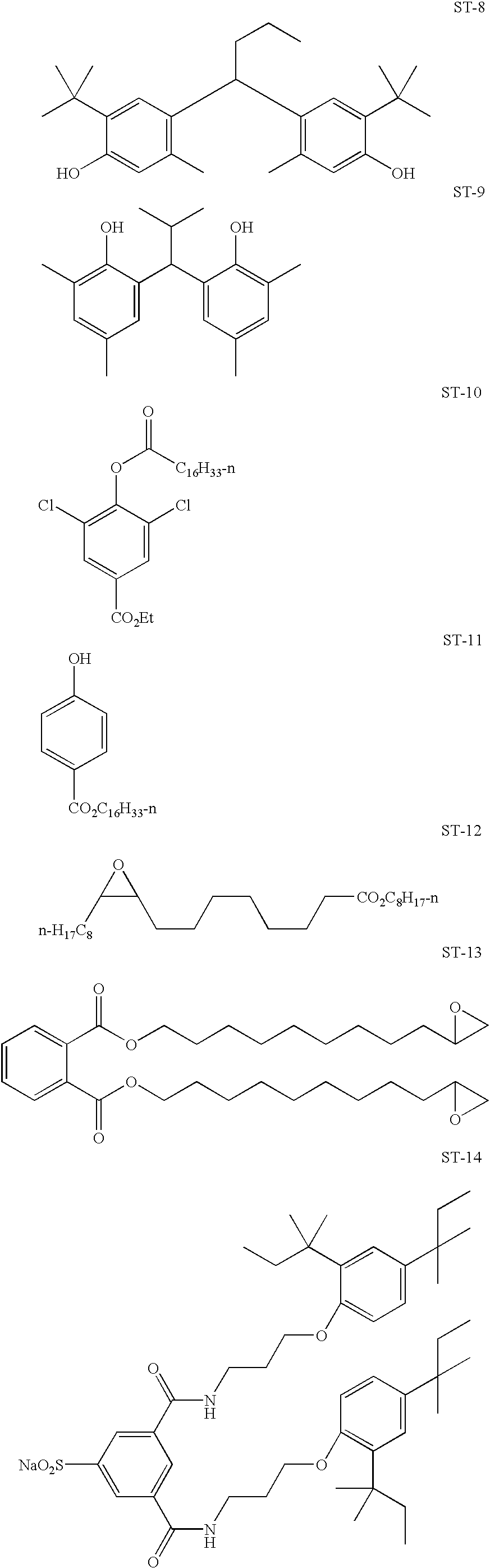


Examples of solvents which may be used in the invention include the following:
| Tritolyl phosphate | S-1 | ||
| Dibutyl phthalate | S-2 | ||
| Diundecyl phthalate | S-3 | ||
| N,N-Diethyldodecanamide | S-4 | ||
| N,N-Dibutyldodecanamide | S-5 | ||
| Tris(2-ethylhexyl)phosphate | S-6 | ||
| Acetyl tributyl citrate | S-7 | ||
| 2,4-Di-tert-pentylphenol | S-8 | ||
| 2-(2-Butoxyethoxy)ethyl acetate | S-9 | ||
| 1,4-Cyclohexyldimethylene bis(2-ethylhexanoate) | S-10 | ||
The dispersions used in photographic elements may also include ultraviolet (UV) stabilizers and so called liquid UV stabilizers such as described in U.S. Pat. Nos. 4,992,358; 4,975,360; and 4,587,346. Examples of UV stabilizers are shown below. 
The aqueous phase may include surfactants. Surfactant may be cationic, anionic, zwitterionic or non-ionic. Useful surfactants include, but are not limited to, the following. 
Further, it is contemplated to stabilize photographic dispersions prone to particle growth through the use of hydrophobic, photographically inert compounds such as disclosed by Zengerle et al in U.S. Ser. No. 07/978,104.
In a preferred embodiment the invention employs recording elements which are constructed to contain at least three silver halide emulsion layer units. A suitable fill color, multilayer format for a recording element used in the invention is represented by Structure I.
| STRUCTURE I |
| Top Most Protective Layer (SOC or size overcoat) with sharpening agent |
| Blue-sensitized |
| yellow dye image-forming silver halide emulsion unit |
| Interlayer |
| Green-sensitized |
| magenta dye image-forming silver halide emulsion unit |
| Interlayer |
| Red-sensitized |
| cyan dye image-forming silver halide emulsion unit |
| ///// Support ///// |
wherein the red-sensitized, cyan dye image-forming silver halide emulsion unit is situated closest to the support; next in order is the green-sensitized, magenta dye image-forming unit, followed by the lowermost blue-sensitized, yellow dye image-forming unit furthest from the support. The image-forming units are separated from each other by hydrophilic colloid interlayers containing an oxidized developing agent scavenger to prevent color contamination. Silver halide emulsions satisfying the grain and gelatino-peptizer requirements described above can be present in any one or combination of the emulsion layer units. Additional useful multicolor, multilayer formats for an element of the invention include structures as described in U.S. Pat. No. 5,783,373. Each of such structures in accordance with the invention preferably would contain at least three silver halide emulsions comprised of high chloride grains having at least 50 percent of their surface area bounded by {100} crystal faces and containing dopants from classes (i) and (ii), as described above. Preferably each of the emulsion layer units contains emulsion satisfying these criteria.
Conventional features that can be incorporated into multilayer (and particularly multicolor) recording elements contemplated for use in the method of the invention are illustrated by Research Disclosure, Item 38957, cited above:
XI. Layers and layer arrangements
XII. Features applicable only to color negative
XIII. Features applicable only to color positive
B. Color reversal
C. Color positives derived from color negatives
XIV. Scan facilitating features.
The recording elements comprising the radiation sensitive high chloride emulsion layers according to this invention can be conventionally optically printed, or in accordance with a particular embodiment of the invention can be image-wise exposed in a pixel-by-pixel mode using suitable high energy radiation sources typically employed in electronic printing methods. Suitable actinic forms of energy encompass the ultraviolet, visible and infrared regions of the electromagnetic spectrum as well as electron-beam radiation and is conveniently supplied by beams from one or more light emitting diodes or lasers, including gaseous or solid state lasers. Exposures can be monochromatic, orthochromatic or panchromatic. For example, when the recording element is a multilayer multicolor element, exposure can be provided by laser or light emitting diode beams of appropriate spectral radiation, for example, infrared, red, green or blue wavelengths, to which such element is sensitive. Multicolor elements can be employed which produce cyan, magenta and yellow dyes as a function of exposure in separate portions of the electromagnetic spectrum, including at least two portions of the infrared region, as disclosed in the previously mentioned U.S. Pat. No. 4,619,892. Suitable exposures include those up to 2000 nm, preferably up to 1500 nm. Suitable light emitting diodes and commercially available laser sources are known and commercially available. Imagewise exposures at ambient, elevated or reduced temperatures and/or pressures can be employed within the useful response range of the recording element determined by conventional sensitometric techniques, as illustrated by T. H. James, The Theory of the Photographic Process, 4th Ed., Macmillan, 1977, Chapters 4, 6, 17, 18 and 23.
It has been observed that anionic [MXxYyLz] hexacoordination complexes, where M is a group 8 or 9 metal (preferably iron, ruthenium or iridium), X is halide or pseudohalide (preferably Cl, Br or CN) x is 3 to 5, Y is H2O, y is 0 or 1, L is a C—C, H—C or C—N—H organic ligand, and Z is 1 or 2, are surprisingly effective in reducing high intensity reciprocity failure (HIRF), low intensity reciprocity failure (LIRF) and thermal sensitivity variance and in in improving latent image keeping (LIK). As herein employed HIRF is a measure of the variance of photographic properties for equal exposures, but with exposure times ranging from 10−1 to 10−6 second. LIRF is a measure of the varinance of photographic properties for equal exposures, but with exposure times ranging from 10−1 to 100 seconds. Although these advantages can be generally compatible with face centered cubic lattice grain structures, the most striking improvements have been observed in high (>50 mole %, preferably ≧90 mole %) chloride emulsions. Preferred C—C, H—C or C—N—H organic ligands are aromatic heterocycles of the type described in U.S. Pat. No. 5,462,849. The most effective C—C, H—C or C—N—H organic ligands are azoles and azines, either unsustituted or containing alkyl, alkoxy or halide substituents, where the alkyl moieties contain from 1 to 8 carbon atoms. Particularly preferred azoles and azines include thiazoles, thiazolines and pyrazines.
The quantity or level of high energy actinic radiation provided to the recording medium by the exposure source is generally at least 10−4 ergs/cm2, typically in the range of about 10−4 ergs/cm2 to 10−3 ergs/cm2 and often from 10−3 ergs/cm2 to 102 ergs/cm2. Exposure of the recording element in a pixel-by-pixel mode as known in the prior art persists for only a very short duration or time. Typical maximum exposure times are up to 100μ seconds, often up to 10μ seconds, and frequently up to only 0.5μ seconds. Single or multiple exposures of each pixel are contemplated. The pixel density is subject to wide variation, as is obvious to those skilled in the art. The higher the pixel density, the sharper the images can be, but at the expense of equipment complexity. In general, pixel densities used in conventional electronic printing methods of the type described herein do not exceed 107 pixels/cm2 and are typically in the range of about 104 to 106 pixels/cm2. An assessment of the technology of high-quality, continuous-tone, color electronic printing using silver halide photographic paper which discusses various features and components of the system, including exposure source, exposure time, exposure level and pixel density and other recording element characteristics is provided in Firth et al., A Continuous-Tone Laser Color Printer, Journal of Imaging Technology, Vol. 14, No. 3, June 1988, which is hereby incorporated herein by reference. As previously indicated herein, a description of some of the details of conventional electronic printing methods comprising scanning a recording element with high energy beams such as light emitting diodes or laser beams, are set forth in Hioki U.S. Pat. No. 5,126,235, European Patent Applications 479 167 A1 and 502 508 A1.
Once imagewise exposed, the recording elements can be processed in any convenient conventional manner to obtain a viewable image. Such processing is illustrated by Research Disclosure, Item 38957, cited above:
XVIII. Chemical development systems
XIX. Development
XX. Desilvering, washing, rinsing and stabilizing
In addition, a useful developer for the inventive material is a homogeneous, single part developing agent. The homogeneous, single-part color developing concentrate is prepared using a critical sequence of steps:
In the first step, an aqueous solution of a suitable color developing agent is prepared. This color developing agent is generally in the form of a sulfate salt. Other components of the solution can include an antioxidant for the color developing agent, a suitable number of alkali metal ions (in an at least stoichiometric proportion to the sulfate ions) provided by an alkali metal base, and a photographically inactive water-miscible or water-soluble hydroxy-containing organic solvent. This solvent is present in the final concentrate at a concentration such that the weight ratio of water to the organic solvent is from about 15:85 to about 50:50.
In this environment, especially at high alkalinity, alkali metal ions and sulfate ions form a sulfate salt that is precipitated in the presence of the hydroxy-containing organic solvent. The precipitated sulfate salt can then be readily removed using any suitable liquid/solid phase separation technique (including filtration, centrifugation or decantation). If the antioxidant is a liquid organic compound, two phases may be formed and the precipitate may be removed by discarding the aqueous phase.
The color developing concentrates of this invention include one or more color developing agents that are well known in the art that, in oxidized form, will react with dye forming color couplers in the processed materials. Such color developing agents include, but are not limited to, aminophenols, p-phenylenediamines (especially N,N-dialkyl-p-phenylenediamines) and others which are well known in the art, such as EP 0 434 097A1 (published Jun. 26, 1991) and EP 0 530 921 A1 (published Mar. 10, 1993). It may be useful for the color developing agents to have one or more water-solubilizing groups as are known in the art. Further details of such materials are provided in Research Disclosure, publication 38957, pages 592-639 (September 1996). Research Disclosure is a publication of Kenneth Mason Publications Ltd., Dudley House, 12 North Street, Emsworth, Hampshire PO10 7DQ England (also available from Emsworth Design Inc., 121 West 19th Street, New York, N.Y. 10011). This reference will be referred to hereinafter as “Research Disclosure”.
Preferred color developing agents include, but are not limited to, N,N-diethyl p-phenylenediamine sulfate (KODAK Color Developing Agent CD-2), 4-amino-3-methyl-N-(2-methane sulfonamidoethyl)aniline sulfate, 4-(N-ethyl-N-β-hydroxyethylamino)-2-methylaniline sulfate (KODAK Color Developing Agent CD-4), p-hydroxyethylethylaminoaniline sulfate, 4-(N-ethyl-N-2-methanesulfonylaminoethyl)-2-methylphenylenediamine sesquisulfate (KODAK Color Developing Agent CD-3), 4-(N-ethyl-N-2-methanesulfonylaminoethyl)-2-methylphenylenediamine sesquisulfate, and others readily apparent to one skilled in the art.
In order to protect the color developing agents from oxidation, one or more antioxidants are generally included in the color developing compositions. Either inorganic or organic antioxidants can be used. Many classes of useful antioxidants are known, including but not limited to, sulfites (such as sodium sulfite, potassium sulfite, sodium bisulfite and potassium metabisulfite), hydroxylamine (and derivatives thereof), hydrazines, hydrazides, amino acids, ascorbic acid (and derivatives thereof), hydroxamic acids, aminoketones, mono- and polysaccharides, mono- and polyamines, quaternary ammonium salts, nitroxy radicals, alcohols, and oximes. Also useful as antioxidants are 1,4-cyclohexadiones. Mixtures of compounds from the same or different classes of antioxidants can also be used if desired.
Especially useful antioxidants are hydroxylamine derivatives as described for example, in U.S. Pat. Nos. 4,892,804, 4,876,174, 5,354,646, and 5,660,974, all noted above, and U.S. Pat. No. 5,646,327 (Burns et al). Many of these antioxidants are mono- and dialkylhydroxylamines having one or more substituents on one or both alkyl groups. Particularly useful alkyl substituents include sulfo, carboxy, amino, sulfonamido, carbonamido, hydroxy and other solubilizing substituents.
More preferably, the noted hydroxylamine derivatives can be mono- or dialkylhydroxylamines having one or more hydroxy substituents on the one or more alkyl groups. Representative compounds of this type are described for example in U.S. Pat. No. 5,709,982 (Marrese et al), incorporated herein by reference, as having the structure I: 
wherein R is hydrogen, a substituted or unsubstituted alkyl group of 1 to 10 carbon atoms, a substituted or unsubstituted hydroxyalkyl group of 1 to 10 carbon atoms, a substituted or unsubstituted cycloalkyl group of 5 to 10 carbon atoms, or a substituted or unsubstituted aryl group having 6 to 10 carbon atoms in the aromatic nucleus.
X1 is —CR2(OH)CHR1— and X2 is —CHR1CR2(OH)— wherein R1 and R2 are independently hydrogen, hydroxy, a substituted or unsubstituted alkyl group or 1 or 2 carbon atoms, a substituted or unsubstituted hydroxyalkyl group of 1 or 2 carbon atoms, or R1 and R2 together represent the carbon atoms necessary to complete a substituted or unsubstituted 5- to 8-membered saturated or unsaturated carbocyclic ring structure.
Y is a substituted or unsubstituted alkylene group having at least 4 carbon atoms, and has an even number of carbon atoms, or Y is a substituted or unsubstituted divalent aliphatic group having an even total number of carbon and oxygen atoms in the chain, provided that the aliphatic group has a least 4 atoms in the chain.
Also in Structure I, m, n and p are independently 0 or 1. Preferably, each of m and n is 1, and p is 0.
Specific di-substituted hydroxylamine antioxidants include, but are not limited to: N,N-bis(2,3-dihydroxypropyl)hydroxylamine, N,N-bis(2-methyl-2,3-dihydroxypropyl)hydroxylamine and N,N-bis(1-hydroxymethyl-2-hydroxy-3-phenylpropyl)hydroxylamine. The first compound is preferred.
These and other objects of the invention will be apparent from the detailed description below. The following examples illustrate the practice of this invention. They are not intended to be exhaustive of all possible variations of the invention. Parts and percentages are by weight unless otherwise indicated.
In this example the color silver halide emulsion of the invention was coated on an imaging support material. The support material of the invention was constructed by laminating biaxially oriented sheets to cellulose photographic grade paper. All samples including the control were made using the same imaging support material. Variations in the examples adjusted the amount of sharpening agent in the top most layer of the imaging member. The sharpening agent of this invention was located above the light sensitive silver halide emulsion. These examples will show the improvement the invention has made compared to the control in for digital printing performance. Further, this example will also demonstrate the image sharpness, whiteness and durability improvement over prior art photographic base materials.
The following is a description of the invention and was prepared by extrusion laminating the following top and bottom biaxially oriented polymer sheets to the photographic grade cellulose paper described below:
Top Sheet (Emulsion Side)
A composite sheet consisting of 5 layers identified as L1, L2, L3, L4, and L5. L1 is the thin colored layer on the outside of the package to which the photosensitive silver halide layer was attached. L2 is the layer to which optical brightener and TiO2 was added. The optical brightener used was Hostalux KS manufactured by Ciba-Geigy. A coated extrusion grade anatase TiO2 was added to both L2 and L4. Table 1 below lists the characteristics of the layers of the top biaxially oriented sheet used in this example.
| TABLE 1 | ||
| Layer | Material | Thickness, μm |
| L1 | Low Density Polyethylene + color | 0.75 |
| concentrate | ||
| L2 | Polypropylene + 24% TiO2 + OB | 6.65 |
| L3 | Voided Polypropylene | 21 |
| L4 | Polypropylene + 18% TiO2 | 6.85 |
| L5 | Polypropylene | 0.76 |
Photographic grade cellulose paper base used in the invention:
Paper base was produced for the invention using a standard fourdrinier paper machine and a blend of mostly bleached hardwood Kraft fibers. The fiber ratio consisted primarily of bleached poplar (38%) and maple/beech (37%) with lesser amounts of birch (18%) and softwood (7%). Fiber length was reduced from 0.73 mm length weighted average as measured by a Kajaani FS-200 to 0.55 mm length using high levels of conical refining and low levels of disc refining. Fiber Lengths from the slurry were measured using an FS-200 Fiber Length Analyzer (Kajaani Automation Inc.). Energy applied to the fibers is indicated by the total Specific Net Refining Power (SNRP) was 127 KW hr/metric ton. Two conical refiners were used in series to provide the total conical refiners SNRP value. This value was obtained by adding the SNRPs of each conical refiner. Two disc refiners were similarly used in series to provide a total Disk SNRP. Neutral sizing chemical addenda, utilized on a dry weight basis, included alkyl ketene dimer at 0.20% addition, cationic starch (1.0%), polyaminoamide epichlorhydrin (0.50%), polyacrylamide resin (0.18%), diaminostilbene optical brightener (0.20%), and sodium bicarbonate. Surface sizing using hydroxyethylated starch and sodium chloride was also employed but is not critical to the invention. In the 3rd Dryer section, ratio drying was utilized to provide a moisture bias from the face side to the wire side of the sheet. The face side (emulsion side) of the sheet was then remoisturized with conditioned steam immediately prior calendering. Sheet temperatures were raised to between 76° C. and 93° C. just prior to and during calendering. The paper was then calendered to an apparent density of 1.17. Moisture levels after the calender were 7.0% to 9.0% by weight. Paper base B was produced at a basis weight of 178 g/mm2 and thickness of 0.1524 mm.
The bottom biaxially oriented sheet laminated to the backside of invention base was a one-side matte finish, one-side treated biaxially oriented polypropylene sheet (25.6 μm thick) (d=0.90 g/cc) consisting of a solid oriented polypropylene layer and a skin layer of a mixture of polyethylenes and a terpolymer comprising ethylene, propylene, and butylene. The skin layer was on the bottom and the polyproylene layer and laminated to the paper.
Bottom Sheet (Backside)
A one-side matte finish, one-side treated polypropylene sheet (26 mm thick) (d=0.9 g/cc) consisting of a solid oriented polypropylene core.
Both the above top and bottom sheets were extrusion laminated to a photographic grade cellulose paper support with a clear polyolefin (25 g/m2).
The top sheet used in this example was coextruded and biaxially oriented. The top sheet was melt extrusion laminated to the above cellulose paper base using a metallocene catalyzed ethylene plastomer (SLP 9088) manufactured by Exxon Chemical Corp. The metallocene catalyzed ethylene plastomer had a density of 0.900 g/cc and a melt index of 14.0.
A coating was then applied to the laminated bottom biaxially oriented sheet on invention using a gravure coater to add the high frequency roughness to the backside. The coating consisted of an aqueous solution containing a sodium salt of styrene sulfonic acid. The coverage used was 25 mg per square meter and then dried to achieve a final web temperature between 55° C., the resultant coalesced latex material produced the desired high frequency roughness pattern. In addition to the sodium salt of styrene sulfonic acid, aluminum modified colloidal silicon dioxide particles were added to the aqueous latex material at a concentration of 50 milligrams per square meter. This further enhanced the high frequency roughness.
The L3 layer for the biaxially oriented sheet is microvoided and further described in Table 2 where the refractive index and geometrical thickness is shown for measurements made along a single slice through the L3 layer; they do not imply continuous layers, a slice along another location would yield different but approximately the same thickness. The areas with a refractive index of 1.0 are voids that are filled with air and the remaining layers are polypropylene.
| TABLE 2 | ||
| Sublayer of L3 | Refractive Index | Thickness, μm |
| 1 | 1.49 | 2.54 |
| 2 | 1 | 1.527 |
| 3 | 1.49 | 2.79 |
| 4 | 1 | 1.016 |
| 5 | 1.49 | 1.778 |
| 6 | 1 | 1.016 |
| 7 | 1.49 | 2.286 |
| 8 | 1 | 1.016 |
| 9 | 1.49 | 2.032 |
| 10 | 1 | 0.762 |
| 11 | 1.49 | 2.032 |
| 12 | 1 | 1.016 |
| 13 | 1.49 | 1.778 |
| 14 | 1 | 1.016 |
| 15 | 1.49 | 2.286 |
The top and bottom films were attached to the paper base stock by melt extrusion of a 10 melt index low density polyethylene coated at a coverage of 12/m2. This polymer was processed at a melt temperature of 610 F.
Silver chloride emulsions were chemically and spectrally sensitized as described below. A biocide comprising a mixture of N-methyl-isothiazolone and N-methyl-5-chloro-isthiazolone was added after sensitization.
Blue Sensitive Emulsion (Blue EM-1)
A high chloride silver halide emulsion is precipitated by adding approximately equimolar silver nitrate and sodium chloride solutions into a well stirred reactor containing glutaryldiaminophenyldisulfide, gelatin peptizer and thioether ripener. Cesium pentachloronitrosylosmate(II) dopant is added during the silver halide grain formation for most of the precipitation, followed by the addition of potassium hexacyanoruthenate(II), potassium (5-methylthiazole)-pentachloroiridate, a small amount of KI solution, and shelling without any dopant. The resultant emulsion contains cubic shaped grains having edge length of 0.6 μm. The emulsion is optimally sensitized by the addition of a colloidal suspension of aurous sulfide and heat ramped to 60° C. during which time blue sensitizing dye BSD-4, potassium hexchloroiridate, Lippmann bromide and 1-(3-acetamidophenyl)-5-mercaptotetrazole were added.
Green Sensitive Emulsion (Green EM-1)
A high chloride silver halide emulsion is precipitated by adding approximately equimolar silver nitrate and sodium chloride solutions into a well stirred reactor containing, gelatin peptizer and thioether ripener. Cesium pentachloronitrosylosmate(II) dopant is added during the silver halide grain formation for most of the precipitation, followed by the addition of potassium (5-methylthiazole)-pentachloroiridate. The resultant emulsion contains cubic shaped grains of 0.3 μm in edgelength size. The emulsion is optimally sensitized by the addition of glutaryldiaminophenyldisulfide, a colloidal suspension of aurous sulfide and heat ramped to 55° C. during which time potassium hexachloroiridate doped Lippmann bromide, a liquid crystalline suspension of green sensitizing dye GSD-1, and 1-(3-acetamidophenyl)-5-mercaptotetrazole were added.
Red Sensitive Emulsion (Red EM-1)
A high chloride silver halide emulsion is precipitated by adding approximately equimolar silver nitrate and sodium chloride solutions into a well stirred reactor containing gelatin peptizer and thioether ripener. During the silver halide grain formation, potassium hexacyanoruthenate(II) and potassium (5-methylthiazole)-pentachloroiridate are added. The resultant emulsion contains cubic shaped grains of 0.4 μm in edgelength size. The emulsion is optimally sensitized by the addition of glutaryldiaminophenyldisulfide, sodium thiosulfate, tripotassium bis{2-[3-(2-sulfobenzamido)phenyl]-mercaptotetrazole} gold(I) and heat ramped to 64° C. during which time 1-(3-acetamidophenyl)-5-mercaptotetrazole, potassium hexachloroiridate, and potassium bromide are added. The emulsion is then cooled to 40° C., pH adjusted to 6.0 and red sensitizing dye RSD-1 is added.
Coupler dispersions were emulsified by methods well known to the art and the following layers were coated on the following support:
The following light sensitive silver halide imaging layers were utilized to prepare photographic print materials utilizing the invention support material and the control support material. The following imaging layers were coated utilizing curtain coating:
| Layer | Item | Laydown (g/m2) |
| Layer 1 | Blue Sensitive Layer | |
| Gelatin | 1.3127 | |
| Blue sensitive silver (Blue EM-1) | 0.2399 | |
| Y-4 | 0.4143 | |
| ST-23 | 0.4842 | |
| Tributyl Citrate | 0.2179 | |
| ST-24 | 0.1211 | |
| ST-16 | 0.0095 | |
| Sodium Phenylmercaptotetrazole | 0.0001 | |
| Piperidino hexose reductone | 0.0024 | |
| 5-chloro-2-methyl-4-isothiazolin-3-one/2- | 0.0002 | |
| methyl-4-isothiazolin-3-one(3/1) | ||
| SF-1 | 0.0366 | |
| Potassium chloride | 0.0204 | |
| Dye-1 | 0.0148 | |
| Layer 2 | Interlayer | |
| Gelatin | 0.7532 | |
| ST-4 | 0.1076 | |
| S-3 | 0.1969 | |
| 5-chloro-2-methyl-4-isothiazolin-3-one/2- | 0.0001 | |
| methyl-4-isothiazolin-3-one(3/1) | ||
| Catechol disulfonate | 0.0323 | |
| SF-1 | 0.0081 | |
| Layer 3 | Green Sensitive Layer | |
| Gelatin | 1.1944 | |
| 1) | 0.1011 | |
| M-4 | 0.2077 | |
| Oleyl Alcohol | 0.2174 | |
| S-3 | 0.1119 | |
| ST-21 | 0.0398 | |
| ST-22 | 0.2841 | |
| Dye-2 | 0.0073 | |
| 5-chloro-2-methyl-4-isothiazolin-3-one/2- | 0.0001 | |
| methyl-4-isothiazolin-3-one(3/1) | ||
| SF-1 | 0.0236 | |
| Potassium chloride | 0.0204 | |
| Sodium Phenylmercaptotetrazole | 0.0007 | |
| Layer 4 | M/C Interlayer | |
| Gelatin | 0.7532 | |
| ST-4 | 0.1076 | |
| S-3 | 0.1969 | |
| Acrylamide/t-Butylacrylamide sulfonate | 0.0541 | |
| copolymer | ||
| Bis-vinylsulfonylmethane | 0.1390 | |
| 3,5-Dinitrobenzoic acid | 0.0001 | |
| Citric acid | 0.0007 | |
| Catechol disulfonate | 0.0323 | |
| 5-chloro-2-methyl-4-isothiazolin-3-one/2- | 0.0001 | |
| methyl-4-isothiazolin-3-one(3/1) | ||
| Layer 5 | Red Sensitive Layer | |
| Gelatin | 1.3558 | |
| Red Sensitive silver (Red EM-1) | 0.1883 | |
| IC-35 | 0.2324 | |
| IC-36 | 0.0258 | |
| UV-2 | 0.3551 | |
| Dibutyl sebacate | 0.4358 | |
| S-6 | 0.1453 | |
| Dye-3 | 0.0229 | |
| Potassium p-toluenethiosulfonate | 0.0026 | |
| 5-chloro-2-methyl-4-isothiazolin-3-one/2- | 0.0001 | |
| methyl-4-isothiazolin-3-one(3/1) | ||
| Sodium Phenylmercaptotetrazole | 0.0005 | |
| SF-1 | 0.0524 | |
| Layer 6 | UV Overcoat | |
| Gelatin | 0.8231 | |
| UV-1 | 0.0355 | |
| UV-2 | 0.2034 | |
| ST-4 | 0.0655 | |
| SF-1 | 0.0125 | |
| S-6 | 0.0797 | |
| 5-chloro-2-methyl-4-isothiazolin-3-one/2- | 0.0001 | |
| methyl-4-isothiazolin-3-one(3/1) | ||
| Layer 7 | SOC (top most layer) | |
| Gelatin | 0.7560 | |
| Ludox AM ™ (colloidal silica) | 0.3241 | |
| Syloid 72 ™ (Glass beads) Particle Size = 2 | 0.2710 | |
| micrometers | ||
| Polydimethylsiloxane (DC200 ™) | 0.0202 | |
| 5-chloro-2-methyl-4-isothiazolin-3-one/2- | 0.0001 | |
| methyl-4-isothiazolin-3-one(3/1) | ||
| SF-2 | 0.0032 | |
| Tergitol 15-S-5 ™ (surfactant) | 0.0020 | |
| SF-1 | 0.0081 | |
| Aerosol OT ™ (surfactant) | 0.0029 | |
The structure of this invention typically is as follows:
| Layer 7 SOC (contains sharpness enhancing | ||
| agent above the light sensitive layer) | ||
| Layer 6 UV Overcoat | ||
| Layer 5 Red Sensitive Layer | ||
| Layer 4 M/C Interlayer | ||
| Layer 3 Green Sensitive Layer | ||
| Layer 2 Interlayer | ||
| Layer 1 Blue Sensitive layer | ||
| LD Polyethylene + color concentrate | ||
| Polypropylene + 24% TiO2 + OB | ||
| Voided Polypropylene | ||
| Polypropylene + 18% TiO2 | ||
| Polypropylene | ||
| LD Polyethylene + 12.5% TiO2 | ||
| Paper Base | ||
| LD Polyethylene | ||
| Matte biaxially oriented backside film | ||
| Antistat | ||
| TABLE 3 | ||
| Sharpening Agent | Sharpness | |
| Level | Measurement | |
| Sample ID | Mg/M2. | MTF Reading |
| Control | 0 | 76.3 |
| 1 | 80.7 | 77.0 |
| 2 | 134.5 | 78 |
| 3 | 202.2 | 81 |
| 4 | 259.0 | 86.8 |
As can be seen in Table 3 as the level of sharpening agent above the silver halide emulsion is increased that the MFT measurement improves. It was totally non-obvious that as the level of the sharpening agent was increased above the light sensitive emulsion that the actual sharpness would increase. There is an improvement with samples 1,2 and 3 but sample 4 showed a preferred significant increase in sharpness in comparison to the control which does not have a sharpness enhancing agent above the light sensitive layer.
| TABLE 4 | ||
| Sharpening Agent | ||
| Location in Silver | Sharpness | |
| Halide Layer | Measurement | |
| Sample ID | 259 Mg/Mt2. | MTF Reading |
| 1 | Layer 7 | 86.6 |
| 2 | Layer 5 | 77.3 |
| 3 | Layer 3 | 76.8 |
| 4 | Layer 1 | 76.5 |
| Control | None | 76.3 |
Table 4 represents the preferred level of sharpening agent placed in different layers of the silver halide photo sensitive emulsion. The control in Table 4 does not have a sharpness enhancing agent in or above the emulsion layers and the MTF is 76.3. Sample 1 in Table 4 is the preferred location for the sharpness enhancing agent. The material is located above the photosensitive layers and has a dramatic improvement in sharpness. When the same amount of sharpness enhancing agent is added to layers 5,3 and 1 which are in the photosensitive layers, the MTF is slightly better than the control but as the sharpness enhancing agent progressively approaches the base portion of the imaging element, the benefit is reduced.
The invention has been described in detail with particular reference to certain preferred embodiments thereof, but it will be understood that variations and modifications can be effected within the spirit and scope of the invention.
Claims (13)
1. An imaging element comprising an image receiving layer and a sharpness enhancing agent material wherein said sharpness enhancing agent comprises glass beads having an average particle size of between 1.5 and 10 micrometers and wherein said sharpness enhancing agent is in a layer above said image receiving layer.
2. The imaging element of claim 1 further comprising wherein said sharpness enhancing agent is present in an amount of between 50 to 600 mg/m2.
3. The imaging element of claim 1 wherein said layer comprising sharpness enhancing agent is coated onto a transparent polymer sheet that overlays said image receiving layer.
4. The imaging element of claim 1 wherein said element has a Gardner 20-degree gloss of less than 30 Gardner units.
5. The imaging element of claim 1 further comprising an oriented polymer sheet base material wherein said oriented polymer sheet comprises a biaxially oriented polyolefin sheet.
6. The imaging element of claim 1 further comprising an oriented polymer sheet base material wherein said oriented polymer sheet comprises an oriented polyester sheet.
7. The imaging element of claim 1 further comprising an oriented polymer sheet base material wherein said oriented polymer sheet comprises at least one voided layer.
8. An imaging element comprising an image receiving layer and a sharpness enhancing agent material wherein said sharpness enhancing agent comprises glass beads having an average particle size of between 1.5 to 10 micrometers and wherein said sharpness enhancing agent is in the image receiving layer.
9. The imaging element of claim 8 further comprising wherein said sharpness enhancing agent is present in an amount of between 50 to 600 mg/m2.
10. The imaging element of claim 8 further comprising an oriented polymer sheet base material wherein said oriented polymer sheet comprises a biaxially oriented polyolefin sheet.
11. The imaging element of claim 10 wherein said element has a Gardner 20-degree gloss of less than 30 Gardner units.
12. The imaging element of claim 8 further comprising an oriented polymer sheet base material wherein said oriented polymer sheet comprises an oriented polyester sheet.
13. The imaging element of claim 8 further comprising an oriented polymer sheet base material wherein said oriented polymer sheet comprises at least one voided layer.
Priority Applications (1)
| Application Number | Priority Date | Filing Date | Title |
|---|---|---|---|
| US09/904,682 US6468709B2 (en) | 2000-01-28 | 2001-07-13 | Biaxially oriented image element with sharpening agent |
Applications Claiming Priority (2)
| Application Number | Priority Date | Filing Date | Title |
|---|---|---|---|
| US09/493,532 US6291148B1 (en) | 2000-01-28 | 2000-01-28 | Biaxially oriented image element with sharpening agent |
| US09/904,682 US6468709B2 (en) | 2000-01-28 | 2001-07-13 | Biaxially oriented image element with sharpening agent |
Related Parent Applications (1)
| Application Number | Title | Priority Date | Filing Date |
|---|---|---|---|
| US09/493,532 Division US6291148B1 (en) | 2000-01-28 | 2000-01-28 | Biaxially oriented image element with sharpening agent |
Publications (2)
| Publication Number | Publication Date |
|---|---|
| US20020018957A1 US20020018957A1 (en) | 2002-02-14 |
| US6468709B2 true US6468709B2 (en) | 2002-10-22 |
Family
ID=23960631
Family Applications (2)
| Application Number | Title | Priority Date | Filing Date |
|---|---|---|---|
| US09/493,532 Expired - Fee Related US6291148B1 (en) | 2000-01-28 | 2000-01-28 | Biaxially oriented image element with sharpening agent |
| US09/904,682 Expired - Fee Related US6468709B2 (en) | 2000-01-28 | 2001-07-13 | Biaxially oriented image element with sharpening agent |
Family Applications Before (1)
| Application Number | Title | Priority Date | Filing Date |
|---|---|---|---|
| US09/493,532 Expired - Fee Related US6291148B1 (en) | 2000-01-28 | 2000-01-28 | Biaxially oriented image element with sharpening agent |
Country Status (2)
| Country | Link |
|---|---|
| US (2) | US6291148B1 (en) |
| EP (1) | EP1122595A3 (en) |
Cited By (2)
| Publication number | Priority date | Publication date | Assignee | Title |
|---|---|---|---|---|
| US6656572B2 (en) * | 2000-02-28 | 2003-12-02 | Felix Schoeller Jr. Foto-Und Spezialpapiere & Co. Kg | Support material |
| US20110191350A1 (en) * | 2008-04-28 | 2011-08-04 | Agency For Science, Technology And Research | Method and system for concentration detection |
Families Citing this family (3)
| Publication number | Priority date | Publication date | Assignee | Title |
|---|---|---|---|---|
| US7008760B1 (en) * | 1999-05-21 | 2006-03-07 | Fuji Photo Film Co., Ltd. | Silver halide color photographic light-sensitive material and method of forming a color image |
| GB0329925D0 (en) * | 2003-12-24 | 2004-01-28 | Eastman Kodak Co | Imaging element having improved durability |
| KR20080061924A (en) * | 2006-12-28 | 2008-07-03 | 엘지디스플레이 주식회사 | Thin film transistor substrate and manufacturing method thereof |
Citations (17)
| Publication number | Priority date | Publication date | Assignee | Title |
|---|---|---|---|---|
| US4040830A (en) * | 1975-08-27 | 1977-08-09 | Polaroid Corporation | Photographic products comprising embossed supports |
| US4047804A (en) | 1973-12-26 | 1977-09-13 | Polaroid Corporation | Anti-reflection coatings for photographic bases |
| US4088487A (en) * | 1975-03-03 | 1978-05-09 | Polaroid Corporation | Diffusion transfer integral film units with flare reducing layers |
| US4355099A (en) * | 1978-07-07 | 1982-10-19 | Ciba-Geigy Ag | Composite photographic material having a thin flexable support and a reflecting layer |
| US4921781A (en) | 1987-09-18 | 1990-05-01 | Konica Corporation | Silver halide photographic material |
| US5176972A (en) * | 1991-09-11 | 1993-01-05 | Polaroid Corporation | Imaging medium with low refractive index layer |
| US5225313A (en) * | 1988-02-15 | 1993-07-06 | Fuji Photo Film Co., Ltd. | Dye fixing elements |
| US5429916A (en) | 1993-06-02 | 1995-07-04 | Fuji Photo Film Co., Ltd. | Silver halide color photographic photosensitive material and method of forming color images |
| US5437956A (en) * | 1993-05-12 | 1995-08-01 | Fuji Photo Film Co., Ltd. | Dye fixing element |
| US5466519A (en) | 1993-04-28 | 1995-11-14 | Fuji Photo Film Co., Ltd. | Support for a photographic printing paper and a manufacturing process therefor |
| US5845575A (en) | 1996-09-24 | 1998-12-08 | Nippon Paper Industries Co., Ltd. | Varnishing film and method of adjusting the surface gloss of prepress color proof using the same |
| US5866282A (en) | 1997-05-23 | 1999-02-02 | Eastman Kodak Company | Composite photographic material with laminated biaxially oriented polyolefin sheets |
| US5888681A (en) | 1997-05-23 | 1999-03-30 | Eastman Kodak Company | Photographic element with microvoided sheet of opalescent appearance |
| US5891612A (en) | 1997-08-28 | 1999-04-06 | Eastman Kodak Company | Photographic elements comprising highly loaded particulate material containing layer |
| US6030759A (en) | 1997-12-24 | 2000-02-29 | Eastman Kodak Company | Composite photographic material with laminated biaxially oriented polyolefin sheets with improved optical performance |
| US6030742A (en) | 1998-11-23 | 2000-02-29 | Eastman Kodak Company | Superior photographic elements including biaxially oriented polyolefin sheets |
| US6187501B1 (en) * | 1999-08-10 | 2001-02-13 | Eastman Kodak Company | Imaging member with tough binder layer |
Family Cites Families (3)
| Publication number | Priority date | Publication date | Assignee | Title |
|---|---|---|---|---|
| JP3023724B2 (en) * | 1991-09-25 | 2000-03-21 | コニカ株式会社 | Silver halide photographic material |
| US5244861A (en) * | 1992-01-17 | 1993-09-14 | Eastman Kodak Company | Receiving element for use in thermal dye transfer |
| JP3109320B2 (en) * | 1993-03-25 | 2000-11-13 | 富士写真フイルム株式会社 | Silver halide photographic material |
-
2000
- 2000-01-28 US US09/493,532 patent/US6291148B1/en not_active Expired - Fee Related
-
2001
- 2001-01-15 EP EP01200118A patent/EP1122595A3/en not_active Withdrawn
- 2001-07-13 US US09/904,682 patent/US6468709B2/en not_active Expired - Fee Related
Patent Citations (17)
| Publication number | Priority date | Publication date | Assignee | Title |
|---|---|---|---|---|
| US4047804A (en) | 1973-12-26 | 1977-09-13 | Polaroid Corporation | Anti-reflection coatings for photographic bases |
| US4088487A (en) * | 1975-03-03 | 1978-05-09 | Polaroid Corporation | Diffusion transfer integral film units with flare reducing layers |
| US4040830A (en) * | 1975-08-27 | 1977-08-09 | Polaroid Corporation | Photographic products comprising embossed supports |
| US4355099A (en) * | 1978-07-07 | 1982-10-19 | Ciba-Geigy Ag | Composite photographic material having a thin flexable support and a reflecting layer |
| US4921781A (en) | 1987-09-18 | 1990-05-01 | Konica Corporation | Silver halide photographic material |
| US5225313A (en) * | 1988-02-15 | 1993-07-06 | Fuji Photo Film Co., Ltd. | Dye fixing elements |
| US5176972A (en) * | 1991-09-11 | 1993-01-05 | Polaroid Corporation | Imaging medium with low refractive index layer |
| US5466519A (en) | 1993-04-28 | 1995-11-14 | Fuji Photo Film Co., Ltd. | Support for a photographic printing paper and a manufacturing process therefor |
| US5437956A (en) * | 1993-05-12 | 1995-08-01 | Fuji Photo Film Co., Ltd. | Dye fixing element |
| US5429916A (en) | 1993-06-02 | 1995-07-04 | Fuji Photo Film Co., Ltd. | Silver halide color photographic photosensitive material and method of forming color images |
| US5845575A (en) | 1996-09-24 | 1998-12-08 | Nippon Paper Industries Co., Ltd. | Varnishing film and method of adjusting the surface gloss of prepress color proof using the same |
| US5866282A (en) | 1997-05-23 | 1999-02-02 | Eastman Kodak Company | Composite photographic material with laminated biaxially oriented polyolefin sheets |
| US5888681A (en) | 1997-05-23 | 1999-03-30 | Eastman Kodak Company | Photographic element with microvoided sheet of opalescent appearance |
| US5891612A (en) | 1997-08-28 | 1999-04-06 | Eastman Kodak Company | Photographic elements comprising highly loaded particulate material containing layer |
| US6030759A (en) | 1997-12-24 | 2000-02-29 | Eastman Kodak Company | Composite photographic material with laminated biaxially oriented polyolefin sheets with improved optical performance |
| US6030742A (en) | 1998-11-23 | 2000-02-29 | Eastman Kodak Company | Superior photographic elements including biaxially oriented polyolefin sheets |
| US6187501B1 (en) * | 1999-08-10 | 2001-02-13 | Eastman Kodak Company | Imaging member with tough binder layer |
Cited By (3)
| Publication number | Priority date | Publication date | Assignee | Title |
|---|---|---|---|---|
| US6656572B2 (en) * | 2000-02-28 | 2003-12-02 | Felix Schoeller Jr. Foto-Und Spezialpapiere & Co. Kg | Support material |
| US20110191350A1 (en) * | 2008-04-28 | 2011-08-04 | Agency For Science, Technology And Research | Method and system for concentration detection |
| US8862581B2 (en) * | 2008-04-28 | 2014-10-14 | Agency For Science Technology And Research | Method and system for concentration detection |
Also Published As
| Publication number | Publication date |
|---|---|
| US20020018957A1 (en) | 2002-02-14 |
| US6291148B1 (en) | 2001-09-18 |
| EP1122595A2 (en) | 2001-08-08 |
| EP1122595A3 (en) | 2004-03-03 |
Similar Documents
| Publication | Publication Date | Title |
|---|---|---|
| US6287743B1 (en) | Imaging material with smooth cellulose base | |
| US6274284B1 (en) | Nacreous imaging material | |
| US6355403B1 (en) | Duplitized reflective members useful for album pages | |
| US6329113B1 (en) | Imaging material with dimensional adjustment by heat | |
| US6296995B1 (en) | Digital photographic element with biaxially oriented polymer base | |
| US6258494B1 (en) | Duplitized photographic depth imaging | |
| US6207362B1 (en) | Tough durable imaging cellulose base material | |
| US6391532B1 (en) | Photographic paper containing calcium carbonate | |
| US6218059B1 (en) | Tough reflective image display material | |
| US6468709B2 (en) | Biaxially oriented image element with sharpening agent | |
| US6475713B1 (en) | Imaging member with polyester adhesive between polymer sheets | |
| US6352822B1 (en) | Polyolefin base display material with tone enhancing layer | |
| US6326109B1 (en) | Two-sided imaging member | |
| US6187501B1 (en) | Imaging member with tough binder layer | |
| US6248483B1 (en) | Paper base transmission display material | |
| US6268116B1 (en) | Scavenger free photographic silver halide print media | |
| US6355404B1 (en) | Polyester base display material with tone enhancing layer | |
| US6440548B1 (en) | Photographic base with oriented polyefin and opacifying layer | |
| US6403292B1 (en) | Duplitized display material with translucent support with specified face to back speed differential | |
| US6312880B1 (en) | Color photographic silver halide print media | |
| US6692798B1 (en) | Kenaf imaging base and method of formation | |
| EP1094363B1 (en) | Photographic element with excellent speed differential for digital and optical exposure devices | |
| US6280916B1 (en) | Silver halide reflection support print media | |
| US6479225B1 (en) | Chromogenic sepia silver halide print material | |
| US6426178B1 (en) | Chromogenic black and white silver halide print material |
Legal Events
| Date | Code | Title | Description |
|---|---|---|---|
| FEPP | Fee payment procedure |
Free format text: PAYOR NUMBER ASSIGNED (ORIGINAL EVENT CODE: ASPN); ENTITY STATUS OF PATENT OWNER: LARGE ENTITY |
|
| FPAY | Fee payment |
Year of fee payment: 4 |
|
| REMI | Maintenance fee reminder mailed | ||
| LAPS | Lapse for failure to pay maintenance fees | ||
| STCH | Information on status: patent discontinuation |
Free format text: PATENT EXPIRED DUE TO NONPAYMENT OF MAINTENANCE FEES UNDER 37 CFR 1.362 |
|
| FP | Lapsed due to failure to pay maintenance fee |
Effective date: 20101022 |