US6469905B1 - Guide rail device for receiving a GBIC module - Google Patents
Guide rail device for receiving a GBIC module Download PDFInfo
- Publication number
- US6469905B1 US6469905B1 US09/935,431 US93543101A US6469905B1 US 6469905 B1 US6469905 B1 US 6469905B1 US 93543101 A US93543101 A US 93543101A US 6469905 B1 US6469905 B1 US 6469905B1
- Authority
- US
- United States
- Prior art keywords
- frame
- guide rail
- circuit board
- printed circuit
- connector
- Prior art date
- Legal status (The legal status is an assumption and is not a legal conclusion. Google has not performed a legal analysis and makes no representation as to the accuracy of the status listed.)
- Expired - Fee Related
Links
Images


Classifications
-
- G—PHYSICS
- G02—OPTICS
- G02B—OPTICAL ELEMENTS, SYSTEMS OR APPARATUS
- G02B6/00—Light guides; Structural details of arrangements comprising light guides and other optical elements, e.g. couplings
- G02B6/24—Coupling light guides
- G02B6/42—Coupling light guides with opto-electronic elements
- G02B6/4201—Packages, e.g. shape, construction, internal or external details
- G02B6/4274—Electrical aspects
- G02B6/4277—Protection against electromagnetic interference [EMI], e.g. shielding means
-
- H—ELECTRICITY
- H01—ELECTRIC ELEMENTS
- H01R—ELECTRICALLY-CONDUCTIVE CONNECTIONS; STRUCTURAL ASSOCIATIONS OF A PLURALITY OF MUTUALLY-INSULATED ELECTRICAL CONNECTING ELEMENTS; COUPLING DEVICES; CURRENT COLLECTORS
- H01R13/00—Details of coupling devices of the kinds covered by groups H01R12/70 or H01R24/00 - H01R33/00
- H01R13/648—Protective earth or shield arrangements on coupling devices, e.g. anti-static shielding
- H01R13/658—High frequency shielding arrangements, e.g. against EMI [Electro-Magnetic Interference] or EMP [Electro-Magnetic Pulse]
- H01R13/6591—Specific features or arrangements of connection of shield to conductive members
- H01R13/6594—Specific features or arrangements of connection of shield to conductive members the shield being mounted on a PCB and connected to conductive members
-
- H—ELECTRICITY
- H01—ELECTRIC ELEMENTS
- H01R—ELECTRICALLY-CONDUCTIVE CONNECTIONS; STRUCTURAL ASSOCIATIONS OF A PLURALITY OF MUTUALLY-INSULATED ELECTRICAL CONNECTING ELEMENTS; COUPLING DEVICES; CURRENT COLLECTORS
- H01R13/00—Details of coupling devices of the kinds covered by groups H01R12/70 or H01R24/00 - H01R33/00
- H01R13/648—Protective earth or shield arrangements on coupling devices, e.g. anti-static shielding
- H01R13/658—High frequency shielding arrangements, e.g. against EMI [Electro-Magnetic Interference] or EMP [Electro-Magnetic Pulse]
- H01R13/6581—Shield structure
- H01R13/6582—Shield structure with resilient means for engaging mating connector
Definitions
- the present invention relates to a guide rail device for receiving a GBIC module therein.
- FIGS. 10, 15, and 16 of Poplawski disclose a guide rail 372 having a box configuration, while FIGS. 14, 17 and 18 disclose another type of guide rail.
- U.S. Pat. No. 5,767,999, issued to Kayner on Jun. 16, 1998 discloses another type of guide rail for receiving a removeable optoelectronic module therein.
- Both Poplawski et, al. and Kayner disclose an electrical connector adapted for electrically engaging with a GBIC module received in the guide rail.
- the electrical connector is mounted on a printed circuit board by solders and does not engage with the guide rail, so is not supported by the guide rail. Therefore, when the GBIC module mates with the electrical connector, the mounting tails of the contacts of the electrical connector are subjected to a force by the GBIC module which may destroy the connection between the mounting tails and the mounting pads on the printed circuit board.
- U.S. Pat. No. 6,047,172 issued to Babineau et al. on Apr. 4, 2000, suggests an arrangement of guide rails in two rows, as shown in FIG. 2 of Babineau. (Note that only one layer is clearly illustrated.)
- the upper guide rails would be mounted on an upper printed circuit board, while the lower guide rails would be mounted on a lower printed circuit board.
- Babineau et al. suggests the idea of arranging the guide rails in two different levels, the implementation of this idea is not cost effective because two different printed circuit boards are required.
- a first object of the present invention is to provide a guide rail elevated a given distance above a printed circuit board and a connector/connector assembly securely fixed to the guide rail;
- a second object of the present invention is to provide a guide rail elevated a given distance above a printed circuit board by supporting poles fastened to the printed circuit board.
- a guide rail for receiving a GBIC module therein comprises a frame defining a receiving space for receiving the GBIC module therein, a connector assembly fixed to the frame, and two pairs of supporting poles fastened to the frame by four bolts for elevating the frame a given distance above a printed circuit board.
- the frame includes four side lugs at outer walls thereof for attaching to selected ends of the respective supporting poles by the four bolts. Lower ends of the supporting poles are mounted onto the printed circuit board.
- the connector assembly has an extension downwardly extending beyond a bottom surface of the frame and mountable to the printed circuit board, also helping to elevate the frame a given distance above the printed circuit board.
- the connector assembly includes a printed substrate, a first connector and a second connector mounted onto upper and lower surfaces of the printed circuit board.
- the first connector has two partitioning ribs on two opposite ends thereof and the frame defines two receiving slots in inner walls of side beams thereof which engageably receive the respective partitioning ribs therein, thereby securing the first connector to the frame.
- the guide rail device further includes a metallic cover attached to the frame for providing EMI shielding to the GBIC module.
- the metallic cover has a hook downwardly extending from an end thereof and the first connector has an ear portion at a top thereof. The hook engageably attaches to the ear portion of the frame to provide a further retention of the first connector to the frame.
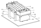
- FIG. 1 is a partially exploded view of a guide rail of the present invention for receiving a GBIC module and a printed circuit board that the guide rail mounts on;
- FIG. 2 is a bottom perspective view of a frame and a first connector of the guide rail shown in FIG. 1;
- FIG. 3 is an enlarged, exploded, perspective view of the frame and the metallic cover shown in FIG. 2;
- FIG. 4 is an enlarged, partially exploded, perspective view of the connector assembly shown in FIG. 1, taken from a rear and right perspective;
- FIG. 5 is a view similar to FIG. 4, but taken from a front and right perspective;
- FIG. 6 is an enlarged, partially exploded, perspective view of the first connector shown in FIG. 4;
- FIG. 7 is an enlarged, partially exploded, perspective view of a second connector shown in FIG. 4;
- FIG. 8 is a cross-sectional view of the second connector taken along line VIII—VIII of FIG. 4;
- FIG. 9 is an assembled, perspective view of the guide rail of the present invention taken from a top-rear perspective
- FIG. 10 is a perspective view of a stacked dual guide rails assembly.
- FIG. 11 is a perspective view of a second embodiment of the present invention.
- the present invention relates to a guide rail 1 mountable onto a printed circuit board 2 (PCB) and adapted for receiving a giga-bit interface convertor (GBIC) module (not shown) therein and electrically connecting the GBIC module to the PCB 2 .
- the guide rail 1 comprises a frame 10 , generally made of metallic material, a metallic cover 12 attached to a top of the frame 10 , an electrical connector assembly 14 engageably fixed to the frame 10 , and four supporting poles 15 with fasteners 78 attached to the frame and the PCB 2 for elevating the frame 10 a predefined distance above the PCB 2 .
- the frame 10 includes a pair of side beams 16 , a rear wall 18 connecting rear ends 20 of the side beams 16 , and a front portion 24 .
- a port 22 is defined through the front portion 24 for entrance of the GBIC module.
- the frame defines a receiving space 26 between the side beams 16 and the rear wall 18 for receiving the GBIC module therein.
- Each side beam 16 defines a receiving slot 17 in an inner wall 19 thereof for retention of the connector assembly 14 .
- the frame 10 also includes two pairs of side lugs 28 at opposite sides thereof, each defining a threaded hole 30 for passage of a fastener 78 therethrough to secure the frame to the supporting poles 15 .
- a reinforced rib 31 is connected between the two side beams 16 of the frame 10 to strengthen the frame 10 .
- the frame 10 further includes a door 32 pivotably attached to the front portion 24 thereof. The door 32 is closed relative to the port 22 before the entrance of the GBIC module and becomes open after the entrance of the GBIC module.
- the frame 10 provides a pair of posts 40 at a bottom thereof for pre-retention of the frame 10 onto the PCB 2 or onto a printed substrate 100 .
- a pair of grounding plates 41 is attached to the front portion 24 of the frame 10 to assure adequate grounding between the guide rail 1 and an inserted GBIC module.
- the metallic cover 12 includes a plate 34 and two side portions 36 bent 90 degrees from opposite edges of the plate 34 for attaching the metallic cover 12 to the frame 10 .
- the metallic cover 12 provides an elastic arm 37 at an end thereof adjacent to the port 22 of the frame 10 for urging a portion 33 of the door 32 to a closed state relative to the port 22 .
- the metallic cover 12 provides a hook 38 downwardly extending from an opposite end thereof for engaging with the connector assembly 14 .
- the connector assembly 14 includes the printed substrate 100 , a first connector 102 and a second connector 104 mounted onto top and bottom surfaces of the printed substrate 100 .
- the first connector 102 includes an insulative housing 50 receiving a plurality of contacts 52 therein, a pair of grounding terminals 54 fixed to opposite side sections (not labeled) of the housing 50 and an EMI shell 56 attached to the housing 50 and enclosing a rear portion of the first connector 102 .
- the first connector 102 has a mating portion 58 at a front portion thereof adapted for engaging with the GBIC module in the frame 10 and a mounting portion 59 at an opposite rear portion thereof for mounting onto the PCB 2 or the printed substrate 100 .
- the housing 50 provides a pair of partitioning ribs 60 with teeth 61 thereon at the side sections thereof and an ear portion 62 at a top thereof.
- the ear portion 62 includes two upstands 64 and a blade 66 connected to the two upstands 64 and defines a recess 68 between the upstands 64 and the blade 66 .
- the second connector 104 includes an insulative extension 106 , a terminal module 108 assembled to the insulative extension 106 and a metallic shield 110 enclosing the insulative extension 106 and the terminal module 108 to provide EMI shielding to the second connector 104 .
- the insulative extension 106 defines a plurality of cavities 112 therethrough.
- the terminal module 108 includes a plurality of terminals 114 arranged in rows, held by an insulative base 116 .
- the metallic shield 110 provides a pair of board-locks 118 at opposite sides thereof which are mountable onto the printed substrate 100 in an upside-down fashion to provide a grounding trace for the metallic shield 110 .
- the cavities 112 each receive a respective terminal 114 therein and have a dimension larger than the transverse size of the respective terminal 114 to achieve a desired impedance of the terminals 114 .
- a narrow air space exists between each terminal 114 and interior sidewalls (not labeled) of each corresponding cavity 112 .
- each cavity 112 includes an outlet (not labeled) at a lower end thereof dimensioned such that the corresponding terminal 114 is snugly fitted therein (see FIG. 8 ).
- the contacts 52 of the first connector 102 and the terminals 114 of the second connector 104 both electrically connect with printed circuit traces (not shown) in the printed substrate 100 . In this way, the contacts 52 are electrically connected with the terminals 114 . Furthermore, the grounding terminals 54 and the EMI shell 56 of the first connector 102 , as well as the board locks 118 of the second connector 104 all electrically connect with grounding circuit traces in the printed substrate 100 , assuring grounding continuity between the first and second connectors.
- the metallic cover 12 is downwardly assembled to the frame 10 by the engagement of the side portions 36 thereof with the side beams 16 .
- the elastic arm 37 elastically urges the door 32 to a closed state.
- the connector assembly 14 is upwardly assembled to the frame 10 by the engagement of the first connector 102 with the two side beams 16 .
- the partitioning ribs 60 are fixedly received in the respective receiving slots 17 in the side beams 16 and the teeth 61 securely engage with peripheral walls of the receiving slots 17 , thereby securely retaining the first connector 102 to the frame 10 .
- the hook 38 of the metallic cover 12 hooks the ear portion 62 of the first connector 102 with keys 43 (See FIG. 1) thereof received in the recess 68 .
- the four supporting poles 15 are attached to the corresponding side lugs 28 by the four fasteners 78 , i.e. bolts, and to the PCB 2 via solders.
- the terminals 114 of the second connector 104 are electrically and mechanically connected to the PCB 2 .
- the second connector 104 and the four supporting poles 15 elevate the frame 10 a predefined distance above the PCB 2 and a space 120 (labeled in FIG. 9) for receiving a second guide rail 122 (shown in FIG. 10) is defined between a bottom surface 124 of the first frame 10 and an upper surface 126 of the PCB 2 .
- the guide rail 1 includes a modified first connector 3 having contacts downwardly extending and directly mounting into the PCB 2 .
- the frame itself might be metallic and integrally form the cover itself.
Abstract
A guide rail (1) for receiving a GBIC module therein mounts to a printed circuit board (2) and includes a frame (10) having a receiving space (26) for receiving the GBIC module therein, a metallic cover (12), and a connector assembly (14) and two pairs of supporting poles (15) fastened to the frame for elevating the frame a given distance above the printed circuit board. The frame includes four side lugs (28) at outer walls thereof for attachment to selected ends of the respective supporting poles by four bolts (78). The lower ends of the supporting poles are mounted onto the printed circuit board. The connector assembly has a second connector (104) downwardly extending beyond a bottom surface (124) of the frame and mounted onto the printed circuit board, helping elevate the frame a given distance above the printed circuit board.
Description
1. Field of the Invention
The present invention relates to a guide rail device for receiving a GBIC module therein.
2. Description of the Related Art
U.S. Pat. No. 5,879,173, issued to Poplawski et, al. on Mar. 9, 1999, discloses a receptacle or guide rail for receiving a removeable optoelectronic module therein. FIGS. 10, 15, and 16 of Poplawski disclose a guide rail 372 having a box configuration, while FIGS. 14, 17 and 18 disclose another type of guide rail. U.S. Pat. No. 5,767,999, issued to Kayner on Jun. 16, 1998, discloses another type of guide rail for receiving a removeable optoelectronic module therein. Both Poplawski et, al. and Kayner disclose an electrical connector adapted for electrically engaging with a GBIC module received in the guide rail. The electrical connector is mounted on a printed circuit board by solders and does not engage with the guide rail, so is not supported by the guide rail. Therefore, when the GBIC module mates with the electrical connector, the mounting tails of the contacts of the electrical connector are subjected to a force by the GBIC module which may destroy the connection between the mounting tails and the mounting pads on the printed circuit board.
U.S. Pat. No. 6,047,172, issued to Babineau et al. on Apr. 4, 2000, suggests an arrangement of guide rails in two rows, as shown in FIG. 2 of Babineau. (Note that only one layer is clearly illustrated.) The upper guide rails would be mounted on an upper printed circuit board, while the lower guide rails would be mounted on a lower printed circuit board. Although Babineau et al. suggests the idea of arranging the guide rails in two different levels, the implementation of this idea is not cost effective because two different printed circuit boards are required.
Hence, an improved stand-off guide rail for receiving a GBIC module is required.
A first object of the present invention is to provide a guide rail elevated a given distance above a printed circuit board and a connector/connector assembly securely fixed to the guide rail; and
A second object of the present invention is to provide a guide rail elevated a given distance above a printed circuit board by supporting poles fastened to the printed circuit board.
To obtain the above objects, a guide rail for receiving a GBIC module therein comprises a frame defining a receiving space for receiving the GBIC module therein, a connector assembly fixed to the frame, and two pairs of supporting poles fastened to the frame by four bolts for elevating the frame a given distance above a printed circuit board. The frame includes four side lugs at outer walls thereof for attaching to selected ends of the respective supporting poles by the four bolts. Lower ends of the supporting poles are mounted onto the printed circuit board. The connector assembly has an extension downwardly extending beyond a bottom surface of the frame and mountable to the printed circuit board, also helping to elevate the frame a given distance above the printed circuit board.
The connector assembly includes a printed substrate, a first connector and a second connector mounted onto upper and lower surfaces of the printed circuit board. The first connector has two partitioning ribs on two opposite ends thereof and the frame defines two receiving slots in inner walls of side beams thereof which engageably receive the respective partitioning ribs therein, thereby securing the first connector to the frame.
The guide rail device further includes a metallic cover attached to the frame for providing EMI shielding to the GBIC module. The metallic cover has a hook downwardly extending from an end thereof and the first connector has an ear portion at a top thereof. The hook engageably attaches to the ear portion of the frame to provide a further retention of the first connector to the frame.
Other objects, advantages and novel features of the invention will become more apparent from the following detailed description of the present embodiment when taken in conjunction with the accompanying drawings.
FIG. 1 is a partially exploded view of a guide rail of the present invention for receiving a GBIC module and a printed circuit board that the guide rail mounts on;
FIG. 2 is a bottom perspective view of a frame and a first connector of the guide rail shown in FIG. 1;
FIG. 3 is an enlarged, exploded, perspective view of the frame and the metallic cover shown in FIG. 2;
FIG. 4 is an enlarged, partially exploded, perspective view of the connector assembly shown in FIG. 1, taken from a rear and right perspective;
FIG. 5 is a view similar to FIG. 4, but taken from a front and right perspective;
FIG. 6 is an enlarged, partially exploded, perspective view of the first connector shown in FIG. 4;
FIG. 7 is an enlarged, partially exploded, perspective view of a second connector shown in FIG. 4;
FIG. 8 is a cross-sectional view of the second connector taken along line VIII—VIII of FIG. 4;
FIG. 9 is an assembled, perspective view of the guide rail of the present invention taken from a top-rear perspective;
FIG. 10 is a perspective view of a stacked dual guide rails assembly; and
FIG. 11 is a perspective view of a second embodiment of the present invention.
Referring to FIG. 1, the present invention relates to a guide rail 1 mountable onto a printed circuit board 2 (PCB) and adapted for receiving a giga-bit interface convertor (GBIC) module (not shown) therein and electrically connecting the GBIC module to the PCB 2. The guide rail 1 comprises a frame 10, generally made of metallic material, a metallic cover 12 attached to a top of the frame 10, an electrical connector assembly 14 engageably fixed to the frame 10, and four supporting poles 15 with fasteners 78 attached to the frame and the PCB 2 for elevating the frame 10 a predefined distance above the PCB 2.
Referring to FIGS. 2 and 3 particularly, the frame 10 includes a pair of side beams 16, a rear wall 18 connecting rear ends 20 of the side beams 16, and a front portion 24. A port 22 is defined through the front portion 24 for entrance of the GBIC module. The frame defines a receiving space 26 between the side beams 16 and the rear wall 18 for receiving the GBIC module therein. Each side beam 16 defines a receiving slot 17 in an inner wall 19 thereof for retention of the connector assembly 14. The frame 10 also includes two pairs of side lugs 28 at opposite sides thereof, each defining a threaded hole 30 for passage of a fastener 78 therethrough to secure the frame to the supporting poles 15. A reinforced rib 31 is connected between the two side beams 16 of the frame 10 to strengthen the frame 10. The frame 10 further includes a door 32 pivotably attached to the front portion 24 thereof. The door 32 is closed relative to the port 22 before the entrance of the GBIC module and becomes open after the entrance of the GBIC module. The frame 10 provides a pair of posts 40 at a bottom thereof for pre-retention of the frame 10 onto the PCB 2 or onto a printed substrate 100. A pair of grounding plates 41 is attached to the front portion 24 of the frame 10 to assure adequate grounding between the guide rail 1 and an inserted GBIC module.
The metallic cover 12 includes a plate 34 and two side portions 36 bent 90 degrees from opposite edges of the plate 34 for attaching the metallic cover 12 to the frame 10. The metallic cover 12 provides an elastic arm 37 at an end thereof adjacent to the port 22 of the frame 10 for urging a portion 33 of the door 32 to a closed state relative to the port 22. The metallic cover 12 provides a hook 38 downwardly extending from an opposite end thereof for engaging with the connector assembly 14.
Referring particularly to FIGS. 4-6, the connector assembly 14 includes the printed substrate 100, a first connector 102 and a second connector 104 mounted onto top and bottom surfaces of the printed substrate 100. The first connector 102 includes an insulative housing 50 receiving a plurality of contacts 52 therein, a pair of grounding terminals 54 fixed to opposite side sections (not labeled) of the housing 50 and an EMI shell 56 attached to the housing 50 and enclosing a rear portion of the first connector 102. The first connector 102 has a mating portion 58 at a front portion thereof adapted for engaging with the GBIC module in the frame 10 and a mounting portion 59 at an opposite rear portion thereof for mounting onto the PCB 2 or the printed substrate 100. The housing 50 provides a pair of partitioning ribs 60 with teeth 61 thereon at the side sections thereof and an ear portion 62 at a top thereof. The ear portion 62 includes two upstands 64 and a blade 66 connected to the two upstands 64 and defines a recess 68 between the upstands 64 and the blade 66.
Referring particularly to FIGS. 7 and 8, the second connector 104 includes an insulative extension 106, a terminal module 108 assembled to the insulative extension 106 and a metallic shield 110 enclosing the insulative extension 106 and the terminal module 108 to provide EMI shielding to the second connector 104. The insulative extension 106 defines a plurality of cavities 112 therethrough. The terminal module 108 includes a plurality of terminals 114 arranged in rows, held by an insulative base 116. The metallic shield 110 provides a pair of board-locks 118 at opposite sides thereof which are mountable onto the printed substrate 100 in an upside-down fashion to provide a grounding trace for the metallic shield 110. The cavities 112 each receive a respective terminal 114 therein and have a dimension larger than the transverse size of the respective terminal 114 to achieve a desired impedance of the terminals 114. Thus, a narrow air space (not labeled) exists between each terminal 114 and interior sidewalls (not labeled) of each corresponding cavity 112. Furthermore, each cavity 112 includes an outlet (not labeled) at a lower end thereof dimensioned such that the corresponding terminal 114 is snugly fitted therein (see FIG. 8).
When assembled in the completed connector assembly 14, the contacts 52 of the first connector 102 and the terminals 114 of the second connector 104 both electrically connect with printed circuit traces (not shown) in the printed substrate 100. In this way, the contacts 52 are electrically connected with the terminals 114. Furthermore, the grounding terminals 54 and the EMI shell 56 of the first connector 102, as well as the board locks 118 of the second connector 104 all electrically connect with grounding circuit traces in the printed substrate 100, assuring grounding continuity between the first and second connectors.
Also referring to FIG. 9, in assembly, the metallic cover 12 is downwardly assembled to the frame 10 by the engagement of the side portions 36 thereof with the side beams 16. The elastic arm 37 elastically urges the door 32 to a closed state. The connector assembly 14 is upwardly assembled to the frame 10 by the engagement of the first connector 102 with the two side beams 16. The partitioning ribs 60 are fixedly received in the respective receiving slots 17 in the side beams 16 and the teeth 61 securely engage with peripheral walls of the receiving slots 17, thereby securely retaining the first connector 102 to the frame 10. The hook 38 of the metallic cover 12 hooks the ear portion 62 of the first connector 102 with keys 43 (See FIG. 1) thereof received in the recess 68. The four supporting poles 15 are attached to the corresponding side lugs 28 by the four fasteners 78, i.e. bolts, and to the PCB 2 via solders. The terminals 114 of the second connector 104 are electrically and mechanically connected to the PCB 2. The second connector 104 and the four supporting poles 15 elevate the frame 10 a predefined distance above the PCB 2 and a space 120 (labeled in FIG. 9) for receiving a second guide rail 122 (shown in FIG. 10) is defined between a bottom surface 124 of the first frame 10 and an upper surface 126 of the PCB 2.
As shown in FIG. 11, an alternative embodiment of the present invention is illustrated. The guide rail 1 includes a modified first connector 3 having contacts downwardly extending and directly mounting into the PCB 2.
Please note that, instead of having a separate metallic cover 12 covering the frame 10 to provide EMI protection, the frame itself might be metallic and integrally form the cover itself.
It is to be understood, however, that even though numerous characteristics and advantages of the present invention have been set forth in the foregoing description, together with details of the structure and function of the invention, the disclosure is illustrative only, and changes may be made in detail, especially in matters of shape, size, and arrangement of parts within the principles of the invention to the full extent indicated by the broad general meaning of the terms in which the appended claims are expressed.
Claims (20)
1. A guide rail system for receiving a GBIC module therein, comprising:
a printed circuit board; and
a guide rail, comprising:
a frame defining a receiving space for receiving the GBIC module therein through a front port thereof;
a metallic cover attached to said frame for providing EMI shielding to said GBIC module; and
a connector assembly engageably attached to said frame and connected to said circuit board and elevating the frame above the printed circuit board so as to receive a second guide rail under the frame, the connector assembly electrically connecting to the printed circuit board and being detachably electrically connectable to a GBIC module inserted into the frame.
2. The guide rail system as recited in claim 1 , wherein the frame includes at lease two side lugs at opposite sides thereof supported by at least a pair of poles arranged between said side lugs and said printed circuit board.
3. The guide rail system as recited in claim 1 , wherein said connector assembly includes a first connector securely received in a rear portion of said frame, a second connector electrically connected to said printed circuit board and a printed substrate electrically joining the first and the second connectors.
4. The guide rail system as recited in claim 3 , wherein said second connector is enclosed by a metal shell.
5. The guide rail system as recited in claim 3 , wherein said second connector includes a plurality of header pins supported by a base, an extension having a plurality of passageways and being attached to the base, and a metal shell securely attaching the base to the extension.
6. The guide rail system as recited in claim 5 , wherein said passageways of said extension each are slightly larger than a cross section of the header pins so that, when assembled, a narrow air space exists between each header pin and interior walls of each corresponding said passageway.
7. The guide rail system as recited in claim 6 , wherein said passageways each include an outlet dimensioned such that the header pin is snugly fitted therein.
8. The guide rail system as recited in claim 5 , wherein said metal shell includes a pair of board locks electrically connected to the substrate.
9. A guide rail assembly adapted for enclosing a GBIC module therein comprising:
a printed circuit board; and
a guide rail comprising:
a frame defining a receiving space for receiving a GBIC module therein and defining a port at a front portion thereof for entrance of the GBIC module;
an electrical connector assembly engageably attached to the frame and electrically mounted onto the printed circuit board, the electrical connector assembly having a printed substrate and a first connector and a second connector respectively electrically mounted on upper and lower surfaces of the printed substrate; and
a space defined under a bottom surface of the frame for receiving a second guide rail.
10. The guide rail assembly as claimed in claim 9 , wherein the first connector electrically connects with the GBIC module and the second connector electrically connects with the printed circuit board.
11. The guide rail assembly as claimed in claim 10 , wherein the frame has a conductive outer surface for providing EMI shielding to the GBIC module.
12. The guide rail assembly as claimed in claim 9 , wherein the connector assembly is securely attached to the frame prior to being mounted onto the printed circuit board.
13. The guide rail assembly as claimed in claim 9 , further including a pair of poles supporting the frame above the printed circuit board, thereby defining the space under the frame for receiving the second guide rail.
14. A guide rail assembly for receiving a GBIC module therein comprising:
a printed circuit board; and
a guide rail, comprising:
a frame defining a receiving space and having a port through a front portion thereof for receiving a GBIC module therein through the front portion thereof, the frame providing side lugs at outer walls thereof; and
supporting poles attached to the respective side lugs of the frame so as to elevate the frame above the printed circuit board a predetermined height adapted for receiving a second guide rail under the frame.
15. The guide rail assembly as claimed in claim 14 , further including an electrical connector assembly engageably attached to the frame, the connector assembly having an extension extending downwardly beyond a bottom surface of the frame and electrically mounting to the printed circuit board.
16. The guide rail assembly as claimed in claim 15 , wherein the electrical connector assembly includes a printed substrate on which the extension mounts, and a first connector mounting to the printed substrate for electrically connecting with a GBIC module mounted in the frame.
17. The guide rail assembly as claimed in claim 14 , further including an electrical connector engageably attached to the frame, the connector having contacts downwardly extending and mounted onto the printed circuit board.
18. The guide rail assembly as claimed in claim 17 , wherein the connector has partitioning ribs on opposite sides thereof engageably received in receiving slots defined in inner walls of side beams of the frame.
19. An guide rail system for receiving two electronic modules therein, comprising:
a printed circuit board;
first and second guide rails stacked with each other and commonly mounted upon the printed circuit board;
said first guide rail including a first frame with a first built-in connector assembly therein; and
said second guide rail including a second frame with a second built-in connector assembly therein; wherein
said first frame is substantially identical to said second frame while the first connector assembly is substantially different from the second connector assembly.
20. The system as recited in claim 19 , wherein the second guide rail is positioned between said first guide rail and the printed circuit board, and a portion of said first connector assembly extends vertically through said second frame toward the printed circuit board while without interference against the second connector assembly.
Priority Applications (3)
| Application Number | Priority Date | Filing Date | Title |
|---|---|---|---|
| US09/935,431 US6469905B1 (en) | 2001-08-22 | 2001-08-22 | Guide rail device for receiving a GBIC module |
| TW090220809U TW534541U (en) | 2001-08-22 | 2001-11-30 | Guide rail device for receiving a GBIC module |
| CN01276961U CN2519438Y (en) | 2001-08-22 | 2001-12-14 | Interface changeover module guidance frame |
Applications Claiming Priority (1)
| Application Number | Priority Date | Filing Date | Title |
|---|---|---|---|
| US09/935,431 US6469905B1 (en) | 2001-08-22 | 2001-08-22 | Guide rail device for receiving a GBIC module |
Publications (1)
| Publication Number | Publication Date |
|---|---|
| US6469905B1 true US6469905B1 (en) | 2002-10-22 |
Family
ID=25467118
Family Applications (1)
| Application Number | Title | Priority Date | Filing Date |
|---|---|---|---|
| US09/935,431 Expired - Fee Related US6469905B1 (en) | 2001-08-22 | 2001-08-22 | Guide rail device for receiving a GBIC module |
Country Status (3)
| Country | Link |
|---|---|
| US (1) | US6469905B1 (en) |
| CN (1) | CN2519438Y (en) |
| TW (1) | TW534541U (en) |
Cited By (53)
| Publication number | Priority date | Publication date | Assignee | Title |
|---|---|---|---|---|
| US20060044774A1 (en) * | 2004-08-30 | 2006-03-02 | Cisco Technology, Inc. (A California Corporation) | Dual-stacked 10 Gigabit X2 uplinks in a single rack unit switch |
| US7180171B1 (en) | 2004-01-08 | 2007-02-20 | Smart Modular Technologies, Inc. | Single IC packaging solution for multi chip modules |
| US20070223208A1 (en) * | 2006-03-27 | 2007-09-27 | Fujitsu Limited | Optical module cage mounting structure |
| WO2008094655A3 (en) * | 2007-01-30 | 2008-09-25 | Pulse Eng Inc | Low-profile connector assembly and methods |
| US20080242127A1 (en) * | 2007-03-27 | 2008-10-02 | Tyco Electronics Corporation | Transceiver receptacle assembly |
| US20090004893A1 (en) * | 2007-06-26 | 2009-01-01 | Hon Hai Pricision Ind. Co., Ltd. | Electrical connector assembly |
| US7601025B1 (en) | 2008-04-18 | 2009-10-13 | Tyco Electronics Corporation | Connector assembly having a jumper assembly |
| US20100099274A1 (en) * | 2008-10-20 | 2010-04-22 | Sung-Yu Hsieh | Sinking Type Electrical Connector and Assembly of the Sinking Type Electrical Connector and a Circuit Board |
| US7872979B1 (en) | 2003-02-10 | 2011-01-18 | Foundry Networks, Llc | System and method to access and address high-speed interface converter devices |
| US20110188815A1 (en) * | 2010-02-04 | 2011-08-04 | Blackwell Jr Chois A | Optical interface cards, assemblies, and related methods, suited for installation and use in antenna system equipment |
| EP2354827A1 (en) * | 2010-02-04 | 2011-08-10 | Corning Cable Systems LLC | Optical interface cards, assemblies, and related methods, suited for installation and use in antenna system equipment |
| CN101728729B (en) * | 2008-10-31 | 2011-08-31 | 纬创资通股份有限公司 | Sinking plate type electric connector and combination of same and circuit board |
| US8433171B2 (en) | 2009-06-19 | 2013-04-30 | Corning Cable Systems Llc | High fiber optic cable packing density apparatus |
| US8538226B2 (en) | 2009-05-21 | 2013-09-17 | Corning Cable Systems Llc | Fiber optic equipment guides and rails configured with stopping position(s), and related equipment and methods |
| US8542973B2 (en) | 2010-04-23 | 2013-09-24 | Ccs Technology, Inc. | Fiber optic distribution device |
| US8625950B2 (en) | 2009-12-18 | 2014-01-07 | Corning Cable Systems Llc | Rotary locking apparatus for fiber optic equipment trays and related methods |
| US8660397B2 (en) | 2010-04-30 | 2014-02-25 | Corning Cable Systems Llc | Multi-layer module |
| US8662760B2 (en) | 2010-10-29 | 2014-03-04 | Corning Cable Systems Llc | Fiber optic connector employing optical fiber guide member |
| US8670238B2 (en) | 2012-01-31 | 2014-03-11 | Avago Technologies General Ip (Singapore) Pte. Ltd. | Guide rail system and a method for providing high-density mounting of optical communications modules |
| US20140094060A1 (en) * | 2012-10-01 | 2014-04-03 | Hamilton Sundstrand Corporation | High voltage connector interfaces |
| US8699838B2 (en) | 2009-05-14 | 2014-04-15 | Ccs Technology, Inc. | Fiber optic furcation module |
| US8705926B2 (en) | 2010-04-30 | 2014-04-22 | Corning Optical Communications LLC | Fiber optic housings having a removable top, and related components and methods |
| US8712206B2 (en) | 2009-06-19 | 2014-04-29 | Corning Cable Systems Llc | High-density fiber optic modules and module housings and related equipment |
| US8718436B2 (en) | 2010-08-30 | 2014-05-06 | Corning Cable Systems Llc | Methods, apparatuses for providing secure fiber optic connections |
| US8879881B2 (en) | 2010-04-30 | 2014-11-04 | Corning Cable Systems Llc | Rotatable routing guide and assembly |
| US8913866B2 (en) | 2010-03-26 | 2014-12-16 | Corning Cable Systems Llc | Movable adapter panel |
| US8953924B2 (en) | 2011-09-02 | 2015-02-10 | Corning Cable Systems Llc | Removable strain relief brackets for securing fiber optic cables and/or optical fibers to fiber optic equipment, and related assemblies and methods |
| US8965168B2 (en) | 2010-04-30 | 2015-02-24 | Corning Cable Systems Llc | Fiber management devices for fiber optic housings, and related components and methods |
| US8989547B2 (en) | 2011-06-30 | 2015-03-24 | Corning Cable Systems Llc | Fiber optic equipment assemblies employing non-U-width-sized housings and related methods |
| US8985862B2 (en) | 2013-02-28 | 2015-03-24 | Corning Cable Systems Llc | High-density multi-fiber adapter housings |
| CN104466540A (en) * | 2013-09-13 | 2015-03-25 | 町洋机电(中国)有限公司 | PCB electric connector module grounding structure |
| US8995812B2 (en) | 2012-10-26 | 2015-03-31 | Ccs Technology, Inc. | Fiber optic management unit and fiber optic distribution device |
| US9008485B2 (en) | 2011-05-09 | 2015-04-14 | Corning Cable Systems Llc | Attachment mechanisms employed to attach a rear housing section to a fiber optic housing, and related assemblies and methods |
| US9020320B2 (en) | 2008-08-29 | 2015-04-28 | Corning Cable Systems Llc | High density and bandwidth fiber optic apparatuses and related equipment and methods |
| US9022814B2 (en) | 2010-04-16 | 2015-05-05 | Ccs Technology, Inc. | Sealing and strain relief device for data cables |
| US9042702B2 (en) | 2012-09-18 | 2015-05-26 | Corning Cable Systems Llc | Platforms and systems for fiber optic cable attachment |
| US9038832B2 (en) | 2011-11-30 | 2015-05-26 | Corning Cable Systems Llc | Adapter panel support assembly |
| US20150146400A1 (en) * | 2013-11-22 | 2015-05-28 | Samtec, Inc. | Two-piece unmate-assist standoff |
| US9059578B2 (en) | 2009-02-24 | 2015-06-16 | Ccs Technology, Inc. | Holding device for a cable or an assembly for use with a cable |
| US9075217B2 (en) | 2010-04-30 | 2015-07-07 | Corning Cable Systems Llc | Apparatuses and related components and methods for expanding capacity of fiber optic housings |
| US9116324B2 (en) | 2010-10-29 | 2015-08-25 | Corning Cable Systems Llc | Stacked fiber optic modules and fiber optic equipment configured to support stacked fiber optic modules |
| US20150244108A1 (en) * | 2014-02-24 | 2015-08-27 | Tyco Electronics Corporation | Receptacle assembly with guide frame |
| US9213161B2 (en) | 2010-11-05 | 2015-12-15 | Corning Cable Systems Llc | Fiber body holder and strain relief device |
| US9250409B2 (en) | 2012-07-02 | 2016-02-02 | Corning Cable Systems Llc | Fiber-optic-module trays and drawers for fiber-optic equipment |
| US9279951B2 (en) | 2010-10-27 | 2016-03-08 | Corning Cable Systems Llc | Fiber optic module for limited space applications having a partially sealed module sub-assembly |
| US9519118B2 (en) | 2010-04-30 | 2016-12-13 | Corning Optical Communications LLC | Removable fiber management sections for fiber optic housings, and related components and methods |
| CN106376208A (en) * | 2016-11-29 | 2017-02-01 | 北京博瑞空间科技发展有限公司 | Unmanned aerial vehicle with rack reinforced structure |
| US9632270B2 (en) | 2010-04-30 | 2017-04-25 | Corning Optical Communications LLC | Fiber optic housings configured for tool-less assembly, and related components and methods |
| US9645317B2 (en) | 2011-02-02 | 2017-05-09 | Corning Optical Communications LLC | Optical backplane extension modules, and related assemblies suitable for establishing optical connections to information processing modules disposed in equipment racks |
| US9720195B2 (en) | 2010-04-30 | 2017-08-01 | Corning Optical Communications LLC | Apparatuses and related components and methods for attachment and release of fiber optic housings to and from an equipment rack |
| US10094996B2 (en) | 2008-08-29 | 2018-10-09 | Corning Optical Communications, Llc | Independently translatable modules and fiber optic equipment trays in fiber optic equipment |
| US10581210B2 (en) * | 2018-07-30 | 2020-03-03 | Te Connectivity Corporation | Receptacle assembly having cabled receptacle connectors |
| US11294135B2 (en) | 2008-08-29 | 2022-04-05 | Corning Optical Communications LLC | High density and bandwidth fiber optic apparatuses and related equipment and methods |
Families Citing this family (2)
| Publication number | Priority date | Publication date | Assignee | Title |
|---|---|---|---|---|
| CN101174737B (en) * | 2006-10-31 | 2010-08-25 | 英业达股份有限公司 | Electric signal connecting structure |
| US8632261B2 (en) * | 2010-04-20 | 2014-01-21 | Hon Hai Precision Industry Co., Ltd. | Integrated and sealed opto-electronic device assembly |
Citations (7)
| Publication number | Priority date | Publication date | Assignee | Title |
|---|---|---|---|---|
| US5967845A (en) * | 1996-11-30 | 1999-10-19 | Hon Hai Precision Ind. Co., Ltd. | Card connector assembly |
| US6095862A (en) * | 1999-02-04 | 2000-08-01 | Molex Incorporated | Adapter frame assembly for electrical connectors |
| USRE36820E (en) * | 1995-01-13 | 2000-08-15 | Methode Electronics, Inc. | Removable optoelectronic module |
| US6276963B1 (en) * | 2000-04-19 | 2001-08-21 | Molex Incorporated | Adapter frame assembly for electrical connectors |
| US20010039143A1 (en) * | 2000-05-08 | 2001-11-08 | Alps Electric Co., Ltd. | Fitting structure for electronic apparatuses of a high productivity |
| US6351394B1 (en) * | 1999-02-12 | 2002-02-26 | Tyco Electronics Corporation | Conductive frame for receiving an electronic module |
| US6368122B2 (en) * | 2000-05-23 | 2002-04-09 | Hon Hai Precisiopn Ind. Co., Ltd. | Bracket having a recoverable door |
-
2001
- 2001-08-22 US US09/935,431 patent/US6469905B1/en not_active Expired - Fee Related
- 2001-11-30 TW TW090220809U patent/TW534541U/en not_active IP Right Cessation
- 2001-12-14 CN CN01276961U patent/CN2519438Y/en not_active Expired - Fee Related
Patent Citations (7)
| Publication number | Priority date | Publication date | Assignee | Title |
|---|---|---|---|---|
| USRE36820E (en) * | 1995-01-13 | 2000-08-15 | Methode Electronics, Inc. | Removable optoelectronic module |
| US5967845A (en) * | 1996-11-30 | 1999-10-19 | Hon Hai Precision Ind. Co., Ltd. | Card connector assembly |
| US6095862A (en) * | 1999-02-04 | 2000-08-01 | Molex Incorporated | Adapter frame assembly for electrical connectors |
| US6351394B1 (en) * | 1999-02-12 | 2002-02-26 | Tyco Electronics Corporation | Conductive frame for receiving an electronic module |
| US6276963B1 (en) * | 2000-04-19 | 2001-08-21 | Molex Incorporated | Adapter frame assembly for electrical connectors |
| US20010039143A1 (en) * | 2000-05-08 | 2001-11-08 | Alps Electric Co., Ltd. | Fitting structure for electronic apparatuses of a high productivity |
| US6368122B2 (en) * | 2000-05-23 | 2002-04-09 | Hon Hai Precisiopn Ind. Co., Ltd. | Bracket having a recoverable door |
Cited By (95)
| Publication number | Priority date | Publication date | Assignee | Title |
|---|---|---|---|---|
| US8320401B2 (en) | 2003-02-10 | 2012-11-27 | Foundry Networks, Llc | System and method to access and address high-speed interface converter devices |
| US20110122966A1 (en) * | 2003-02-10 | 2011-05-26 | Foundry Networks, Llc | System and method to access and address high-speed interface converter devices |
| US7872979B1 (en) | 2003-02-10 | 2011-01-18 | Foundry Networks, Llc | System and method to access and address high-speed interface converter devices |
| US7180171B1 (en) | 2004-01-08 | 2007-02-20 | Smart Modular Technologies, Inc. | Single IC packaging solution for multi chip modules |
| WO2006026286A2 (en) | 2004-08-30 | 2006-03-09 | Cisco Technology, Inc. | Dual-stacked 10 gigabit x2 uplinks in a single rack unit switch |
| WO2006026286A3 (en) * | 2004-08-30 | 2006-10-26 | Cisco Tech Inc | Dual-stacked 10 gigabit x2 uplinks in a single rack unit switch |
| US7136289B2 (en) * | 2004-08-30 | 2006-11-14 | Cisco Technology, Inc. | Dual-stacked 10 Gigabit X2 uplinks in a single rack unit switch |
| EP1792529A2 (en) * | 2004-08-30 | 2007-06-06 | Cisco Technology, Inc. | Dual-stacked 10 gigabit x2 uplinks in a single rack unit switch |
| EP1792529A4 (en) * | 2004-08-30 | 2008-07-02 | Cisco Tech Inc | Dual-stacked 10 gigabit x2 uplinks in a single rack unit switch |
| US20060044774A1 (en) * | 2004-08-30 | 2006-03-02 | Cisco Technology, Inc. (A California Corporation) | Dual-stacked 10 Gigabit X2 uplinks in a single rack unit switch |
| US7463495B2 (en) * | 2006-03-27 | 2008-12-09 | Fujitsu Limited | Optical module cage mounting structure |
| US20070223208A1 (en) * | 2006-03-27 | 2007-09-27 | Fujitsu Limited | Optical module cage mounting structure |
| US20080299826A1 (en) * | 2007-01-30 | 2008-12-04 | Yican Cheng | Low-profile connector assembly and methods |
| US7845975B2 (en) | 2007-01-30 | 2010-12-07 | Pulse Engineering, Inc. | Low-profile connector assembly and methods |
| WO2008094655A3 (en) * | 2007-01-30 | 2008-09-25 | Pulse Eng Inc | Low-profile connector assembly and methods |
| EP2115827A2 (en) * | 2007-01-30 | 2009-11-11 | Pulse Engineering, Inc. | Low-profile connector assembly and methods |
| EP2115827A4 (en) * | 2007-01-30 | 2010-12-01 | Pulse Eng Inc | Low-profile connector assembly and methods |
| US20080242127A1 (en) * | 2007-03-27 | 2008-10-02 | Tyco Electronics Corporation | Transceiver receptacle assembly |
| US7452216B2 (en) * | 2007-03-27 | 2008-11-18 | Tyco Electronics Corporation | Transceiver receptacle assembly |
| US20090004893A1 (en) * | 2007-06-26 | 2009-01-01 | Hon Hai Pricision Ind. Co., Ltd. | Electrical connector assembly |
| US7654863B2 (en) * | 2007-06-26 | 2010-02-02 | Hon Hai Precision Ind. Co., Ltd. | Electrical connector assembly |
| CN101562289B (en) * | 2008-04-18 | 2013-07-17 | 泰科电子公司 | Connector assembly having a jumper assembly |
| US20090264010A1 (en) * | 2008-04-18 | 2009-10-22 | Phillips Michael J | Connector assembly having a jumper assembly |
| US7601025B1 (en) | 2008-04-18 | 2009-10-13 | Tyco Electronics Corporation | Connector assembly having a jumper assembly |
| US10459184B2 (en) | 2008-08-29 | 2019-10-29 | Corning Optical Communications LLC | High density and bandwidth fiber optic apparatuses and related equipment and methods |
| US9020320B2 (en) | 2008-08-29 | 2015-04-28 | Corning Cable Systems Llc | High density and bandwidth fiber optic apparatuses and related equipment and methods |
| US10120153B2 (en) | 2008-08-29 | 2018-11-06 | Corning Optical Communications, Llc | Independently translatable modules and fiber optic equipment trays in fiber optic equipment |
| US10094996B2 (en) | 2008-08-29 | 2018-10-09 | Corning Optical Communications, Llc | Independently translatable modules and fiber optic equipment trays in fiber optic equipment |
| US10126514B2 (en) | 2008-08-29 | 2018-11-13 | Corning Optical Communications, Llc | Independently translatable modules and fiber optic equipment trays in fiber optic equipment |
| US11294136B2 (en) | 2008-08-29 | 2022-04-05 | Corning Optical Communications LLC | High density and bandwidth fiber optic apparatuses and related equipment and methods |
| US10222570B2 (en) | 2008-08-29 | 2019-03-05 | Corning Optical Communications LLC | Independently translatable modules and fiber optic equipment trays in fiber optic equipment |
| US10416405B2 (en) | 2008-08-29 | 2019-09-17 | Corning Optical Communications LLC | Independently translatable modules and fiber optic equipment trays in fiber optic equipment |
| US11754796B2 (en) | 2008-08-29 | 2023-09-12 | Corning Optical Communications LLC | Independently translatable modules and fiber optic equipment trays in fiber optic equipment |
| US10444456B2 (en) | 2008-08-29 | 2019-10-15 | Corning Optical Communications LLC | High density and bandwidth fiber optic apparatuses and related equipment and methods |
| US11294135B2 (en) | 2008-08-29 | 2022-04-05 | Corning Optical Communications LLC | High density and bandwidth fiber optic apparatuses and related equipment and methods |
| US11092767B2 (en) | 2008-08-29 | 2021-08-17 | Corning Optical Communications LLC | High density and bandwidth fiber optic apparatuses and related equipment and methods |
| US10422971B2 (en) | 2008-08-29 | 2019-09-24 | Corning Optical Communicatinos LLC | High density and bandwidth fiber optic apparatuses and related equipment and methods |
| US11609396B2 (en) | 2008-08-29 | 2023-03-21 | Corning Optical Communications LLC | High density and bandwidth fiber optic apparatuses and related equipment and methods |
| US10564378B2 (en) | 2008-08-29 | 2020-02-18 | Corning Optical Communications LLC | High density and bandwidth fiber optic apparatuses and related equipment and methods |
| US10606014B2 (en) | 2008-08-29 | 2020-03-31 | Corning Optical Communications LLC | Independently translatable modules and fiber optic equipment trays in fiber optic equipment |
| US9910236B2 (en) | 2008-08-29 | 2018-03-06 | Corning Optical Communications LLC | High density and bandwidth fiber optic apparatuses and related equipment and methods |
| US10852499B2 (en) | 2008-08-29 | 2020-12-01 | Corning Optical Communications LLC | High density and bandwidth fiber optic apparatuses and related equipment and methods |
| US11086089B2 (en) | 2008-08-29 | 2021-08-10 | Corning Optical Communications LLC | High density and bandwidth fiber optic apparatuses and related equipment and methods |
| US20100099274A1 (en) * | 2008-10-20 | 2010-04-22 | Sung-Yu Hsieh | Sinking Type Electrical Connector and Assembly of the Sinking Type Electrical Connector and a Circuit Board |
| US7744410B2 (en) * | 2008-10-20 | 2010-06-29 | Wistron Corporation | Sinking type electrical connector and assembly of the sinking type electrical connector and a circuit board |
| CN101728729B (en) * | 2008-10-31 | 2011-08-31 | 纬创资通股份有限公司 | Sinking plate type electric connector and combination of same and circuit board |
| US9059578B2 (en) | 2009-02-24 | 2015-06-16 | Ccs Technology, Inc. | Holding device for a cable or an assembly for use with a cable |
| US8699838B2 (en) | 2009-05-14 | 2014-04-15 | Ccs Technology, Inc. | Fiber optic furcation module |
| US8538226B2 (en) | 2009-05-21 | 2013-09-17 | Corning Cable Systems Llc | Fiber optic equipment guides and rails configured with stopping position(s), and related equipment and methods |
| US9075216B2 (en) | 2009-05-21 | 2015-07-07 | Corning Cable Systems Llc | Fiber optic housings configured to accommodate fiber optic modules/cassettes and fiber optic panels, and related components and methods |
| US8712206B2 (en) | 2009-06-19 | 2014-04-29 | Corning Cable Systems Llc | High-density fiber optic modules and module housings and related equipment |
| US8433171B2 (en) | 2009-06-19 | 2013-04-30 | Corning Cable Systems Llc | High fiber optic cable packing density apparatus |
| US8625950B2 (en) | 2009-12-18 | 2014-01-07 | Corning Cable Systems Llc | Rotary locking apparatus for fiber optic equipment trays and related methods |
| EP2354827A1 (en) * | 2010-02-04 | 2011-08-10 | Corning Cable Systems LLC | Optical interface cards, assemblies, and related methods, suited for installation and use in antenna system equipment |
| US8992099B2 (en) | 2010-02-04 | 2015-03-31 | Corning Cable Systems Llc | Optical interface cards, assemblies, and related methods, suited for installation and use in antenna system equipment |
| US20110188815A1 (en) * | 2010-02-04 | 2011-08-04 | Blackwell Jr Chois A | Optical interface cards, assemblies, and related methods, suited for installation and use in antenna system equipment |
| US8593828B2 (en) | 2010-02-04 | 2013-11-26 | Corning Cable Systems Llc | Communications equipment housings, assemblies, and related alignment features and methods |
| US8913866B2 (en) | 2010-03-26 | 2014-12-16 | Corning Cable Systems Llc | Movable adapter panel |
| US9022814B2 (en) | 2010-04-16 | 2015-05-05 | Ccs Technology, Inc. | Sealing and strain relief device for data cables |
| US8542973B2 (en) | 2010-04-23 | 2013-09-24 | Ccs Technology, Inc. | Fiber optic distribution device |
| US9519118B2 (en) | 2010-04-30 | 2016-12-13 | Corning Optical Communications LLC | Removable fiber management sections for fiber optic housings, and related components and methods |
| US9720195B2 (en) | 2010-04-30 | 2017-08-01 | Corning Optical Communications LLC | Apparatuses and related components and methods for attachment and release of fiber optic housings to and from an equipment rack |
| US8660397B2 (en) | 2010-04-30 | 2014-02-25 | Corning Cable Systems Llc | Multi-layer module |
| US9075217B2 (en) | 2010-04-30 | 2015-07-07 | Corning Cable Systems Llc | Apparatuses and related components and methods for expanding capacity of fiber optic housings |
| US8965168B2 (en) | 2010-04-30 | 2015-02-24 | Corning Cable Systems Llc | Fiber management devices for fiber optic housings, and related components and methods |
| US8705926B2 (en) | 2010-04-30 | 2014-04-22 | Corning Optical Communications LLC | Fiber optic housings having a removable top, and related components and methods |
| US8879881B2 (en) | 2010-04-30 | 2014-11-04 | Corning Cable Systems Llc | Rotatable routing guide and assembly |
| US9632270B2 (en) | 2010-04-30 | 2017-04-25 | Corning Optical Communications LLC | Fiber optic housings configured for tool-less assembly, and related components and methods |
| US8718436B2 (en) | 2010-08-30 | 2014-05-06 | Corning Cable Systems Llc | Methods, apparatuses for providing secure fiber optic connections |
| US9279951B2 (en) | 2010-10-27 | 2016-03-08 | Corning Cable Systems Llc | Fiber optic module for limited space applications having a partially sealed module sub-assembly |
| US8662760B2 (en) | 2010-10-29 | 2014-03-04 | Corning Cable Systems Llc | Fiber optic connector employing optical fiber guide member |
| US9116324B2 (en) | 2010-10-29 | 2015-08-25 | Corning Cable Systems Llc | Stacked fiber optic modules and fiber optic equipment configured to support stacked fiber optic modules |
| US9213161B2 (en) | 2010-11-05 | 2015-12-15 | Corning Cable Systems Llc | Fiber body holder and strain relief device |
| US10481335B2 (en) | 2011-02-02 | 2019-11-19 | Corning Optical Communications, Llc | Dense shuttered fiber optic connectors and assemblies suitable for establishing optical connections for optical backplanes in equipment racks |
| US9645317B2 (en) | 2011-02-02 | 2017-05-09 | Corning Optical Communications LLC | Optical backplane extension modules, and related assemblies suitable for establishing optical connections to information processing modules disposed in equipment racks |
| US9008485B2 (en) | 2011-05-09 | 2015-04-14 | Corning Cable Systems Llc | Attachment mechanisms employed to attach a rear housing section to a fiber optic housing, and related assemblies and methods |
| US8989547B2 (en) | 2011-06-30 | 2015-03-24 | Corning Cable Systems Llc | Fiber optic equipment assemblies employing non-U-width-sized housings and related methods |
| US8953924B2 (en) | 2011-09-02 | 2015-02-10 | Corning Cable Systems Llc | Removable strain relief brackets for securing fiber optic cables and/or optical fibers to fiber optic equipment, and related assemblies and methods |
| US9038832B2 (en) | 2011-11-30 | 2015-05-26 | Corning Cable Systems Llc | Adapter panel support assembly |
| US8670238B2 (en) | 2012-01-31 | 2014-03-11 | Avago Technologies General Ip (Singapore) Pte. Ltd. | Guide rail system and a method for providing high-density mounting of optical communications modules |
| US9250409B2 (en) | 2012-07-02 | 2016-02-02 | Corning Cable Systems Llc | Fiber-optic-module trays and drawers for fiber-optic equipment |
| US9042702B2 (en) | 2012-09-18 | 2015-05-26 | Corning Cable Systems Llc | Platforms and systems for fiber optic cable attachment |
| US20140094060A1 (en) * | 2012-10-01 | 2014-04-03 | Hamilton Sundstrand Corporation | High voltage connector interfaces |
| US8936484B2 (en) * | 2012-10-01 | 2015-01-20 | Hamilton Sundstrand Corporation | High voltage connector interfaces |
| US8995812B2 (en) | 2012-10-26 | 2015-03-31 | Ccs Technology, Inc. | Fiber optic management unit and fiber optic distribution device |
| US8985862B2 (en) | 2013-02-28 | 2015-03-24 | Corning Cable Systems Llc | High-density multi-fiber adapter housings |
| CN104466540A (en) * | 2013-09-13 | 2015-03-25 | 町洋机电(中国)有限公司 | PCB electric connector module grounding structure |
| CN104466540B (en) * | 2013-09-13 | 2016-07-06 | 町洋机电(中国)有限公司 | The ground structure of PCB electric connector module |
| US20150146400A1 (en) * | 2013-11-22 | 2015-05-28 | Samtec, Inc. | Two-piece unmate-assist standoff |
| US9374900B2 (en) * | 2013-11-22 | 2016-06-21 | Samtec, Inc. | Two-piece unmate-assist standoff |
| US9583886B2 (en) * | 2014-02-24 | 2017-02-28 | Te Connectivity Corporation | Receptacle assembly with guide frame |
| US20150244108A1 (en) * | 2014-02-24 | 2015-08-27 | Tyco Electronics Corporation | Receptacle assembly with guide frame |
| CN106376208B (en) * | 2016-11-29 | 2021-12-03 | 北京博瑞空间科技发展有限公司 | Unmanned aerial vehicle with frame additional strengthening |
| CN106376208A (en) * | 2016-11-29 | 2017-02-01 | 北京博瑞空间科技发展有限公司 | Unmanned aerial vehicle with rack reinforced structure |
| US10581210B2 (en) * | 2018-07-30 | 2020-03-03 | Te Connectivity Corporation | Receptacle assembly having cabled receptacle connectors |
Also Published As
| Publication number | Publication date |
|---|---|
| TW534541U (en) | 2003-05-21 |
| CN2519438Y (en) | 2002-10-30 |
Similar Documents
| Publication | Publication Date | Title |
|---|---|---|
| US6469905B1 (en) | Guide rail device for receiving a GBIC module | |
| US6582244B2 (en) | Connector interface and retention system for high-density connector | |
| US7108554B2 (en) | Electrical connector with shielding member | |
| US7997922B2 (en) | Vertical connector guide with press arm | |
| US8267722B2 (en) | Cable connector assembly having improved grounding member | |
| JP2006522485A (en) | Shield cage with multiple module bays | |
| GB2310769A (en) | Shielded electrical jack | |
| US7704098B2 (en) | Registered jack with enhanced EMI protection | |
| US7008762B2 (en) | Electrical connector assembly having grounding function | |
| US6454580B1 (en) | Guide rail for receiving a GBIC module | |
| US8033866B2 (en) | Receptacle connector having reinforced bracket increasing overall rigidity | |
| JP2000195595A (en) | Electrical connector for connecting flexible circuit board to printed circuit board | |
| US6511345B1 (en) | Guide rail assembly for receiving optoelectronic modules | |
| US20040087217A1 (en) | Electrical connector with rear retention mechanism of outer shell | |
| US6623297B2 (en) | GBIC electrical connector assembly | |
| US6619984B2 (en) | Electrical connector having improved shielding | |
| US6884112B1 (en) | Electrical connector having improved securing member | |
| CN111834824A (en) | Socket connector with grounding bus plug connector | |
| US6247969B1 (en) | Card-receiving connector with grounding terminal | |
| US7223107B2 (en) | Board-mounted electrical connector with balanced solder attachment to a circuit board | |
| KR100532561B1 (en) | Surface mount connector having improved terminal structure | |
| JP3370280B2 (en) | Narrow-pitch multistage board connector and shield shell fittings used therefor | |
| US20050112946A1 (en) | Electrical connector capable of bearing high voltage | |
| US6293825B1 (en) | Electrical connector | |
| US6793538B2 (en) | Slim modular jack |
Legal Events
| Date | Code | Title | Description |
|---|---|---|---|
| AS | Assignment |
Owner name: HON HAI PRECISION IND. CO., LTD., TAIWAN Free format text: ASSIGNMENT OF ASSIGNORS INTEREST;ASSIGNOR:HWANG, JENG-YIH;REEL/FRAME:012113/0721 Effective date: 20010806 |
|
| FPAY | Fee payment |
Year of fee payment: 4 |
|
| REMI | Maintenance fee reminder mailed | ||
| LAPS | Lapse for failure to pay maintenance fees | ||
| STCH | Information on status: patent discontinuation |
Free format text: PATENT EXPIRED DUE TO NONPAYMENT OF MAINTENANCE FEES UNDER 37 CFR 1.362 |
|
| FP | Lapsed due to failure to pay maintenance fee |
Effective date: 20101022 |