US6477969B2 - Boat with center pontoon and separate motor mount - Google Patents

Boat with center pontoon and separate motor mount Download PDF

Info

Publication number
US6477969B2
US6477969B2 US09/849,690 US84969001A US6477969B2 US 6477969 B2 US6477969 B2 US 6477969B2 US 84969001 A US84969001 A US 84969001A US 6477969 B2 US6477969 B2 US 6477969B2
Authority
US
United States
Prior art keywords
watercraft
pontoon
mount
engine
platform
Prior art date
Legal status (The legal status is an assumption and is not a legal conclusion. Google has not performed a legal analysis and makes no representation as to the accuracy of the status listed.)
Expired - Fee Related
Application number
US09/849,690
Other versions
US20020046688A1 (en
Inventor
Linda Schell-Tomczak
Anthony J. Seconsky
Kevin L. Huff
Current Assignee (The listed assignees may be inaccurate. Google has not performed a legal analysis and makes no representation or warranty as to the accuracy of the list.)
Maurell Products Inc
Original Assignee
Maurell Products Inc
Priority date (The priority date is an assumption and is not a legal conclusion. Google has not performed a legal analysis and makes no representation as to the accuracy of the date listed.)
Filing date
Publication date
Application filed by Maurell Products Inc filed Critical Maurell Products Inc
Priority to US09/849,690 priority Critical patent/US6477969B2/en
Assigned to MAURELL PRODUCTS, INC. reassignment MAURELL PRODUCTS, INC. ASSIGNMENT OF ASSIGNORS INTEREST (SEE DOCUMENT FOR DETAILS). Assignors: HUFF, KEVIN L., SCHELL-TOMCZAK, LINDA, SECONSKY, ANTHONY J.
Publication of US20020046688A1 publication Critical patent/US20020046688A1/en
Application granted granted Critical
Publication of US6477969B2 publication Critical patent/US6477969B2/en
Anticipated expiration legal-status Critical
Expired - Fee Related legal-status Critical Current

Links

Images

Classifications

    • BPERFORMING OPERATIONS; TRANSPORTING
    • B63SHIPS OR OTHER WATERBORNE VESSELS; RELATED EQUIPMENT
    • B63HMARINE PROPULSION OR STEERING
    • B63H20/00Outboard propulsion units, e.g. outboard motors or Z-drives; Arrangements thereof on vessels
    • B63H20/02Mounting of propulsion units
    • B63H20/06Mounting of propulsion units on an intermediate support
    • BPERFORMING OPERATIONS; TRANSPORTING
    • B63SHIPS OR OTHER WATERBORNE VESSELS; RELATED EQUIPMENT
    • B63BSHIPS OR OTHER WATERBORNE VESSELS; EQUIPMENT FOR SHIPPING 
    • B63B1/00Hydrodynamic or hydrostatic features of hulls or of hydrofoils
    • B63B1/02Hydrodynamic or hydrostatic features of hulls or of hydrofoils deriving lift mainly from water displacement
    • B63B1/10Hydrodynamic or hydrostatic features of hulls or of hydrofoils deriving lift mainly from water displacement with multiple hulls
    • B63B1/12Hydrodynamic or hydrostatic features of hulls or of hydrofoils deriving lift mainly from water displacement with multiple hulls the hulls being interconnected rigidly
    • B63B1/125Hydrodynamic or hydrostatic features of hulls or of hydrofoils deriving lift mainly from water displacement with multiple hulls the hulls being interconnected rigidly comprising more than two hulls
    • BPERFORMING OPERATIONS; TRANSPORTING
    • B63SHIPS OR OTHER WATERBORNE VESSELS; RELATED EQUIPMENT
    • B63HMARINE PROPULSION OR STEERING
    • B63H20/00Outboard propulsion units, e.g. outboard motors or Z-drives; Arrangements thereof on vessels
    • B63H20/08Means enabling movement of the position of the propulsion element, e.g. for trim, tilt or steering; Control of trim or tilt
    • B63H20/10Means enabling trim or tilt, or lifting of the propulsion element when an obstruction is hit; Control of trim or tilt

Definitions

  • Pontoon boats include a pair of elongated pontoons which support a platform spanning between the pontoons.
  • An outboard engine or outboard motor (terms used interchangeably) is supported from the platform at a position intermediate the pontoons at a rear of the boat.
  • An engine mount is connected to an underside of the platform.
  • the engine mount comprises an elongated hollow body or trough which extends longitudinally and rearwardly of the rear end (stem end) of the platform. The body is exposed to the water beneath the boat.
  • the engine mount is substantially closed except for a top opening at a rear of the boat.
  • a fuel tank is held within the body, accessed through the top opening.
  • the outboard motor is bolted to the rear wall of the body.
  • the prior known mount is non-adjustably fixed to the platform. No range of vertical adjustment for the outboard engine is provided by the mount.
  • the present inventors have recognized that it would be desirable to provide a center pontoon for a watercraft, to improve performance and turning of the watercraft, wherein the center pontoon is compatible with a vertically adjustable engine mount of the watercraft.
  • a watercraft such as a pontoon boat, includes a platform supported on a pair of outside pontoons and a center pontoon.
  • the center pontoon includes a substantially cylindrical body having a relieved top surface at a rear end of the cylindrical body.
  • the watercraft includes an adjustable engine mount for mounting an outboard motor or engine at adjustable heights with respect to the platform, and in effect, to the waterline.
  • the engine mount includes a mount body pivotally connected to the platform at a forward end, and vertically adjustable with respect to the platform at a rearward end.
  • the mount body includes a rear wall which carries the outboard motor.
  • the mount body overlies the center pontoon in substantial part over the relieved top surface of the cylindrical body.
  • the relieved top surface of the cylindrical body of the center pontoon allows clearance for adjustable vertical movement of the mount body.
  • the relieved top surface can be formed by a flat wall portion angled downwardly toward a rear of the boat.
  • the relieved top surface can be formed by a concave profile trough or indent, preferably sloped downwardly toward a rear of the boat.
  • center pontoon increases the flotation, turning and performance of the boat. Providing the flexibility of vertical adjustment of the outboard motor with the center pontoon further increases the overall turning and performance of the boat.
  • the present invention may create a “hard water pocket” in the vicinity of the propeller which also improves performance of the watercraft.
  • the adjustable engine mount includes a tapered, elongated body which is couplable to, and vertically adjustable relative to, the hull of the boat.
  • the body has a first, smaller end oriented toward the bow of the watercraft and a second, wider end positioned adjacent to the stern of the craft.
  • An engine-mounting wall or mounting plate is attached to the second end of the body.
  • An outboard motor or outboard engine can be attached to the mounting plate.
  • the elevation of the outboard motor with respect to the watercraft or with respect to the waterline can be adjusted.
  • the adjustment can be utilized to optimize performance of an outboard motor.
  • the adjustment provides flexibility and facilitates the use of different model outboard motors on the watercraft.
  • FIG. 1 is a perspective view of a watercraft utilizing the center pontoon and engine mount of the present invention, wherein an outboard motor is not shown for clarity of view of the engine mount;
  • FIG. 2 is a sectional view taken generally along line 2 — 2 of FIG. 1, with an outboard motor installed;
  • FIG. 3 is an enlarged sectional view taken generally along lines 3 — 3 of FIG. 2;
  • FIG. 4 is a fragmentary perspective view of an end of the watercraft with the engine mount removed for purpose of description;
  • FIG. 5 is a fragmentary perspective view of a rear end of an alternate embodiment wartercraft
  • FIG. 6 is an elevational view of the center pontoon taken from FIG. 5;
  • FIG. 7 is a right side view of the center pontoon of FIG. 6 .
  • FIG. 1 illustrates a watercraft 20 .
  • the watercraft 20 includes a platform 26 supported on parallel, outside, buoyancy-providing housings, such as outside pontoons 30 , 32 , and a center buoyancy-providing housing, such as a center pontoon 34 .
  • the platform 26 is adapted to carry payload, such as passengers or cargo.
  • the platform is shown as a plain floor surrounded by a railing 33 .
  • the platform could be adapted to provide seating for people, or storage for cargo, or structure for a houseboat, as only a few examples.
  • the engine mount 36 includes a trough-like hollow mount body 40 , closed at a rear end (stern end) by an engine-mounting wall or plate 44 .
  • An outboard motor (shown in FIG. 2) is coupled to the wall 44 as described below.
  • the mount body 40 is connected intermittently along its length to support rails 50 , 52 .
  • the support rails 50 , 52 are connected intermittently along lengths thereof to an underside of the platform 26 .
  • the engine mount 36 extends rearwardly of a back edge 56 of the platform 26 , defining a top opening 58 .
  • a fuel tank 59 can be carried in with the mount body 40 , exposed through the opening 58 .
  • FIG. 2 illustrates the engine mount 36 beneath the watercraft 20 .
  • the rail 52 is connected to the body 40 by five bolted connections 62 , 64 , 66 , 68 , 70 .
  • An end plate 74 substantially closes a front end (bow end) of the mount body 40 .
  • a motor plate 80 supports an outboard motor 82 .
  • the motor plate 80 is bolted to the engine-mounting wall 44 using bolts 83 .
  • the mounting wall 44 includes a top channel portion 45 which reinforces the top free edge of the wall 44 and also provides a guiding retainer for a fuel line, control cables or other like devices.
  • connection 62 , 64 , 66 , 68 , 70 can be loosened and the mount body 40 can be pivoted about the connection 62 , in the direction R, to adjust the elevation of the motor 82 . After adjustment, all the connections 62 , 64 , 66 , 68 , 70 can be tightened.
  • the center pontoon 34 includes a cylindrical body 89 with a relieved top surface 90 (shown in FIG. 3) which receives a bottom portion 92 of the mount body 40 therein to partially overlap in vertical profile. This allows an increased vertical adjustment range of the mount body between the platform and the center pontoon.
  • FIG. 3 illustrates the body 40 has side walls 106 , 108 and bottom walls 112 , 114 .
  • the side wall 106 , 108 are bolted to the side rails 50 , 52 respectively, by the connections 62 , 64 , 66 , 68 , 70 .
  • the side rails are bolted to the deck 26 .
  • the lower portion 92 of the mount body 40 includes the bottom walls 112 , 114 .
  • the relieved top surface 90 of the pontoon cylindrical body 89 is shaped by a V-shaped wall 91 inclined downwardly toward a rear of the watercraft.
  • the center pontoon 34 also includes a flat end wall 96 .
  • the cylindrical body 89 , the V-shaped wall 91 and the end wall 96 are integrally welded together to form a sealed pontoon.
  • FIG. 4 illustrates the V-shaped wall 91 forming the relieved surface 90 .
  • the center pontoon 34 , and the outer pontoons 30 , 32 are connected to the deck 26 using a plurality of M-shaped brackets 98 which are welded to the pontoon 34 and fastened or welded to the deck 26 .
  • An alternate center pontoon 34 ′ includes a flat inclined top surface 90 ′ formed by a flat inclined wall 91 ′.
  • the inclined wall 91 ′, an alternate cylindrical body 89 ′ and an alternate end wall 96 ′ are integrally welded together to form a sealed pontoon.
  • the inclined wall 91 ′ allows an increased vertical range of motion for a rear end of the mount body 40 ′.
  • FIGS. 6 and 7 illustrate the pontoon 34 ′ of FIG. 5 in more detail.
  • the center pontoon is attached to the deck 26 by a plurality of M-shaped brackets 98 spaced along a length of the pontoon 34 ′.
  • One or more wings or splash guards 128 are arranged on a front end of the pontoon to decrease splashing and increase performance.

Abstract

A center pontoon for a pontoon boat provides improved performance and an adjustable engine mount. The adjustable engine mount makes it possible to adjust the relative position of an outboard engine relative to the waterline of the boat. The center pontoon includes a relieved top surface for allowing a vertical adjustment movement of the engine mount. The mount has an elongated, mount body which is adjustably attached to the bottom of the hull of the boat by a pair of spaced apart, elongated mounting rails. The mount body has a vertical profile that is compatibly shaped with the relieved top surface to provide sufficient vertical adjustable movement. The engine mount is located between a pontoon boat deck and the center pontoon.

Description

This application claims the benefit of U.S. Provisional Application No. 60/243,113 filed Oct. 25, 2000.
FIELD OF THE INVENTION
The invention pertains to mounts for outboard engines. More particularly, the invention pertains to adjustable mounts intended for use with pontoon boats.
BACKGROUND OF THE INVENTION
Pontoon boats include a pair of elongated pontoons which support a platform spanning between the pontoons. An outboard engine or outboard motor (terms used interchangeably) is supported from the platform at a position intermediate the pontoons at a rear of the boat.
An engine mount is connected to an underside of the platform. The engine mount comprises an elongated hollow body or trough which extends longitudinally and rearwardly of the rear end (stem end) of the platform. The body is exposed to the water beneath the boat. The engine mount is substantially closed except for a top opening at a rear of the boat. A fuel tank is held within the body, accessed through the top opening. The outboard motor is bolted to the rear wall of the body.
The prior known mount is non-adjustably fixed to the platform. No range of vertical adjustment for the outboard engine is provided by the mount.
U.S. Ser. No. 09/641,061, filed Aug. 17, 2000, entitled “Engine Mount,” and assigned to the assignee of the present application, discloses a vertically adjustable engine mount for a watercraft, arranged between side pontoons.
The present inventors have recognized that it would be desirable to provide a center pontoon for a watercraft, to improve performance and turning of the watercraft, wherein the center pontoon is compatible with a vertically adjustable engine mount of the watercraft.
SUMMARY OF THE INVENTION
A watercraft, such as a pontoon boat, includes a platform supported on a pair of outside pontoons and a center pontoon. The center pontoon includes a substantially cylindrical body having a relieved top surface at a rear end of the cylindrical body.
The watercraft includes an adjustable engine mount for mounting an outboard motor or engine at adjustable heights with respect to the platform, and in effect, to the waterline. The engine mount includes a mount body pivotally connected to the platform at a forward end, and vertically adjustable with respect to the platform at a rearward end.
The mount body includes a rear wall which carries the outboard motor. The mount body overlies the center pontoon in substantial part over the relieved top surface of the cylindrical body.
The relieved top surface of the cylindrical body of the center pontoon allows clearance for adjustable vertical movement of the mount body. The relieved top surface can be formed by a flat wall portion angled downwardly toward a rear of the boat. Alternatively, the relieved top surface can be formed by a concave profile trough or indent, preferably sloped downwardly toward a rear of the boat.
The use of a center pontoon increases the flotation, turning and performance of the boat. Providing the flexibility of vertical adjustment of the outboard motor with the center pontoon further increases the overall turning and performance of the boat.
The present invention may create a “hard water pocket” in the vicinity of the propeller which also improves performance of the watercraft.
The adjustable engine mount includes a tapered, elongated body which is couplable to, and vertically adjustable relative to, the hull of the boat. The body has a first, smaller end oriented toward the bow of the watercraft and a second, wider end positioned adjacent to the stern of the craft.
An engine-mounting wall or mounting plate is attached to the second end of the body. An outboard motor or outboard engine can be attached to the mounting plate.
By vertically adjusting the body with respect to the hull, the elevation of the outboard motor with respect to the watercraft or with respect to the waterline, can be adjusted. The adjustment can be utilized to optimize performance of an outboard motor. The adjustment provides flexibility and facilitates the use of different model outboard motors on the watercraft.
Numerous other advantages and features of the present invention will become readily apparent from the following detailed description of the invention and the embodiments thereof, from the claims and from the accompanying drawings.
BRIEF DESCRIPTION OF THE DRAWINGS
FIG. 1 is a perspective view of a watercraft utilizing the center pontoon and engine mount of the present invention, wherein an outboard motor is not shown for clarity of view of the engine mount;
FIG. 2 is a sectional view taken generally along line 22 of FIG. 1, with an outboard motor installed;
FIG. 3 is an enlarged sectional view taken generally along lines 33 of FIG. 2;
FIG. 4 is a fragmentary perspective view of an end of the watercraft with the engine mount removed for purpose of description;
FIG. 5 is a fragmentary perspective view of a rear end of an alternate embodiment wartercraft;
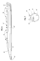
FIG. 6 is an elevational view of the center pontoon taken from FIG. 5; and
FIG. 7 is a right side view of the center pontoon of FIG. 6.
DETAILED DESCRIPTION OF THE PREFERRED EMBODIMENTS
While this invention is susceptible of embodiment in many different forms, there are shown in the drawings and will be described herein in detail specific embodiments thereof with the understanding that the present disclosure is to be considered as an exemplification of the principles of the invention and is not intended to limit the invention to the specific embodiments illustrated.
FIG. 1 illustrates a watercraft 20. The watercraft 20 includes a platform 26 supported on parallel, outside, buoyancy-providing housings, such as outside pontoons 30, 32, and a center buoyancy-providing housing, such as a center pontoon 34. The platform 26 is adapted to carry payload, such as passengers or cargo. For simplicity, the platform is shown as a plain floor surrounded by a railing 33. The platform could be adapted to provide seating for people, or storage for cargo, or structure for a houseboat, as only a few examples.
Mounted to the platform 26, above the center pontoon 34, is an elongated engine mount 36. The engine mount 36 is described more completely in U.S. Ser. No. 09/641,061 filed Aug. 17, 2000, herein incorporated by reference.
The engine mount 36 includes a trough-like hollow mount body 40, closed at a rear end (stern end) by an engine-mounting wall or plate 44. An outboard motor (shown in FIG. 2) is coupled to the wall 44 as described below. The mount body 40 is connected intermittently along its length to support rails 50, 52. The support rails 50, 52 are connected intermittently along lengths thereof to an underside of the platform 26.
The engine mount 36 extends rearwardly of a back edge 56 of the platform 26, defining a top opening 58. A fuel tank 59 can be carried in with the mount body 40, exposed through the opening 58.
FIG. 2 illustrates the engine mount 36 beneath the watercraft 20. The rail 52 is connected to the body 40 by five bolted connections 62, 64, 66, 68, 70. An end plate 74 substantially closes a front end (bow end) of the mount body 40.
A motor plate 80 supports an outboard motor 82. The motor plate 80 is bolted to the engine-mounting wall 44 using bolts 83. The mounting wall 44 includes a top channel portion 45 which reinforces the top free edge of the wall 44 and also provides a guiding retainer for a fuel line, control cables or other like devices.
The connection 62, 64, 66, 68, 70 can be loosened and the mount body 40 can be pivoted about the connection 62, in the direction R, to adjust the elevation of the motor 82. After adjustment, all the connections 62, 64, 66, 68, 70 can be tightened.
The center pontoon 34 includes a cylindrical body 89 with a relieved top surface 90 (shown in FIG. 3) which receives a bottom portion 92 of the mount body 40 therein to partially overlap in vertical profile. This allows an increased vertical adjustment range of the mount body between the platform and the center pontoon.
FIG. 3 illustrates the body 40 has side walls 106, 108 and bottom walls 112, 114. The side wall 106, 108 are bolted to the side rails 50, 52 respectively, by the connections 62, 64, 66, 68, 70. The side rails are bolted to the deck 26. The lower portion 92 of the mount body 40 includes the bottom walls 112, 114.
The relieved top surface 90 of the pontoon cylindrical body 89 is shaped by a V-shaped wall 91 inclined downwardly toward a rear of the watercraft. The center pontoon 34 also includes a flat end wall 96. The cylindrical body 89, the V-shaped wall 91 and the end wall 96 are integrally welded together to form a sealed pontoon.
FIG. 4 illustrates the V-shaped wall 91 forming the relieved surface 90. The center pontoon 34, and the outer pontoons 30, 32, are connected to the deck 26 using a plurality of M-shaped brackets 98 which are welded to the pontoon 34 and fastened or welded to the deck 26.
FIG. 5 illustrates an alternate embodiment mount body 40′ having a flat bottom area 92′ formed by a flat bottom wall 112′, replacing the obliquely arranged bottom walls 112, 114 of the first embodiment.
An alternate center pontoon 34′ includes a flat inclined top surface 90′ formed by a flat inclined wall 91′. The inclined wall 91′, an alternate cylindrical body 89′ and an alternate end wall 96′ are integrally welded together to form a sealed pontoon. The inclined wall 91′ allows an increased vertical range of motion for a rear end of the mount body 40′.
FIGS. 6 and 7 illustrate the pontoon 34′ of FIG. 5 in more detail. The center pontoon is attached to the deck 26 by a plurality of M-shaped brackets 98 spaced along a length of the pontoon 34′. One or more wings or splash guards 128 are arranged on a front end of the pontoon to decrease splashing and increase performance.
From the foregoing, it will be observed that numerous variations and modifications may be effected without departing from the spirit and scope of the invention. It is to be understood that no limitation with respect to the specific apparatus illustrated herein is intended or should be inferred. It is, of course, intended to cover by the appended claims all such modifications as fall within the scope of the claims.

Claims (36)

What is claimed:
1. A watercraft comprising:
an above-water portion for a user;
an elongated, sealed, buoyancy-providing housing coupled to a water side of the above-water portion wherein the housing is centrally located with respect to one dimension of the above-water portion;
an engine mount movably coupled to the above-water portion and the housing; and
wherein the housing is substantially cylindrical with at least one surface adjacent to the engine mount and oriented in a direction to provide an adjustment region into which at least a portion of the engine mount can be moved throughout a predetermined range.
2. A watercraft as in claim 1, wherein the above-water portion is elongated and substantially rigid with a central axis and wherein the housing extends substantially along that axis.
3. A watercraft as in claim 2, wherein the engine mount is coupled to an end of the above-water portion on the central axis.
4. A watercraft as in claim 3, wherein the engine mount is sandwiched between the above-water portion and the housing.
5. A watercraft as in claim 4, wherein when the above-water portion is oriented substantially horizontal and the engine mount is movable generally perpendicularly.
6. A watercraft as in claim 1, wherein the housing has at least two surfaces adjacent to the engine mount so as to provide the adjustment region.
7. A watercraft as in claim 6, wherein the two surfaces form a V-shaped region which extends away from the engine mount.
8. A watercraft as in claim 7, which includes first and second spaced apart buoyancy-providing elements with the housing located therebetween.
9. A watercraft as in claim 8, wherein the buoyancy-providing elements are cylindrical and elongated.
10. A watercraft as in claim 9, wherein the housing is elongated and cylindrical except in the vicinity of the engine mount and wherein the housing extends parallel to and between the buoyancy-providing elements.
11. A watercraft as in claim 10, wherein the above water portion has a planar deck and wherein the deck extends parallel to the housing.
12. A watercraft as in claim 10, wherein an engine is coupled to the engine mount to propel the watercraft.
13. A pontoon boat comprising:
a deck;
at least one buoyancy-providing pontoon coupled to a water side of the deck;
an engine mount movably coupled to the water side of the deck adjacent to at least an end of the pontoon and movable relative to the pontoon;
wherein an end of the pontoon exhibits an engine mount depression permitting movement of the mount, and
wherein the depression includes first and second intersecting planar surfaces.
14. A pontoon boat as in claim 13 which includes second and third buoyancy-providing pontoons coupled to the water side of the deck spaced apart from the one pontoon.
15. A pontoon boat as in claim 13, wherein the engine mount extends from an end of the pontoon.
16. A pontoon boat as in claim 15, wherein the engine mount is movable in a direction generally perpendicular to the direction in which the mount extends from the end of the pontoon.
17. A pontoon boat as in claim 13, which includes an engine coupled to the mount with a water side extension for propelling the boat in a water environment.
18. A pontoon boat comprising:
a deck;
at least one buoyancy-providing pontoon coupled to a water side of the deck;
an engine mount movably coupled to the water side of the deck adjacent to at least an end of the pontoon and movable relative to the pontoon;
wherein an end of the pontoon exhibits an engine mount depression permitting movement of the mount, and
wherein the engine mount, the water side extension and the engine mount depression cooperate to enhance performance of the boat.
19. A pontoon boat as in claim 18 which includes second and third buoyancy providing pontoons coupled to the water side of the deck spaced apart from the one pontoon.
20. A watercraft, comprising:
a platform for carrying a payload;
a pair of side pontoons arranged beneath the platform for supporting the platform above a water line;
an engine mount assembly arranged between the pontoons, said engine mount assembly including an elongated mount body pivotally connected at a front end thereof to said platform and connected at a rear end thereof at a selected vertical position to said platform, and an engine-mounting wall connected to said mount body at said rear end;
a center pontoon arranged beneath said platform between said side pontoons; and
an outboard motor mounted to said engine-mounting wall.
21. A watercraft according to claim 20, wherein said center pontoon comprises a substantially cylindrically body with a relieved top surface, said relieved top surface positioned in part beneath said elongated mount body to allow a range of vertical, position-adjusting movement of a rear end of said mount body.
22. The watercraft according to claim 20, wherein said center pontoon comprises a flat end wall at a rear end thereof.
23. The watercraft according to claim 20, wherein said relieved surface comprises a flat wall angled downwardly toward a rear of said watercraft.
24. The watercraft according to claim 20, wherein said relieved surface comprises a concave wall.
25. The watercraft according to claim 20, wherein said concave wall is angled downwardly toward a rear of said watercraft.
26. The watercraft according to claim 20, wherein said relieved surface comprises a V-shaped indentation.
27. The watercraft according to claim 20, wherein said V-shaped indentation is angled downwardly toward a rear of said watercraft.
28. The watercraft according to claim 20, wherein said mount body is connected to said platform at said rear end thereof by means of a wall of said platform connected to said mount body, one of said wall and said mount body having a plurality of selectable holes and a respective other of said wall and said mount body having at least one protrusion insertable into one of said selectable holes.
29. The watercraft according to claim 20, comprising a first rail extending between said rear end and said front end of said mount body, said first rail connected to said platform, said mount body pivotally connected to said first rail at said front end and selectively fastened at said rear end to adjust an elevation of said engine mount.
30. The watercraft according to claim 29, comprising a second rail extending between said rear end and said front end of said mount body, said second rail connected to said platform, said mount body pivotally connected to said second rail at said front end and selectively fastened at said rear end to adjust an elevation of said engine mounts, said first and second rails arranged on opposite sides of said mount body.
31. A watercraft, comprising:
a platform for carrying a payload;
a pair of side pontoons arranged beneath the platform for supporting the platform above a water line;
an engine mount assembly arranged between the pontoons, said engine mount assembly including an elongated mount body pivotally connected at a first end thereof to said platform and connected at a second, displaced end thereof at a selected position to said platform, and an engine-mounting wall connected to said mount body at said second end;
a center pontoon arranged beneath said platform between said side pontoon.
32. A watercraft according to claim 31, wherein said center pontoon comprises a substantially cylindrical body with a relieved top surface, said relieved top surface positioned in part beneath said elongated mount body to allow a range of position-adjusting movement of the second end of said mount body in a direction generally perpendicular to the platform.
33. A watercraft according to claim 31 wherein said center pontoon comprises a flat end wall at a rear end thereof.
34. A watercraft according to claim 31, wherein said relieved surface comprises a flat wall angled downwardly toward an end of said watercraft.
35. A watercraft according to claim 31, wherein said relieved surface comprises a concave wall.
36. A watercraft as in claim 31 which includes an outboard motor mounted to said engine-mounting wall.
US09/849,690 2000-10-25 2001-05-03 Boat with center pontoon and separate motor mount Expired - Fee Related US6477969B2 (en)

Priority Applications (1)

Application Number Priority Date Filing Date Title
US09/849,690 US6477969B2 (en) 2000-10-25 2001-05-03 Boat with center pontoon and separate motor mount

Applications Claiming Priority (2)

Application Number Priority Date Filing Date Title
US24311300P 2000-10-25 2000-10-25
US09/849,690 US6477969B2 (en) 2000-10-25 2001-05-03 Boat with center pontoon and separate motor mount

Publications (2)

Publication Number Publication Date
US20020046688A1 US20020046688A1 (en) 2002-04-25
US6477969B2 true US6477969B2 (en) 2002-11-12

Family

ID=26935601

Family Applications (1)

Application Number Title Priority Date Filing Date
US09/849,690 Expired - Fee Related US6477969B2 (en) 2000-10-25 2001-05-03 Boat with center pontoon and separate motor mount

Country Status (1)

Country Link
US (1) US6477969B2 (en)

Cited By (12)

* Cited by examiner, † Cited by third party
Publication number Priority date Publication date Assignee Title
US20060130724A1 (en) * 2004-12-22 2006-06-22 Maurell Products, Inc. Multiply hinged sundeck for pontoon boat
US20060260527A1 (en) * 2005-04-15 2006-11-23 Ackerbloom Robert N Watercraft hull having a constant flow tunnel and corresponding method
US7182033B1 (en) 2006-01-10 2007-02-27 Brunswick Corporation Self-contained marine propulsion system for a pontoon boat
US7185599B1 (en) 2006-01-10 2007-03-06 Brunswick Corporation Jet drive propulsion system for a pontoon boat
US20090031939A1 (en) * 2007-07-31 2009-02-05 Bennington Marine Llc Pontoon boat having improved buoyancy
US20090067381A1 (en) * 2002-10-11 2009-03-12 Sandro Grech Transport efficiency optimization for mobile ipv6
US7533622B1 (en) 2007-10-09 2009-05-19 Brunswick Corporation Pontoon boat with pod container assembled from above deck surface
US20090130926A1 (en) * 2007-08-21 2009-05-21 Brunswick Corporation Vibration isolation system for marine vessels
US9022342B2 (en) * 2011-02-28 2015-05-05 Lermayer Outdoors, Inc. Jack plate for pontoon boat
US9475548B1 (en) 2014-08-29 2016-10-25 Cobalt Boats, LLC Multi-hull platform boat
US10486772B1 (en) * 2017-09-01 2019-11-26 Malcolm Sohm Watercraft lifting fin
US10953955B1 (en) 2010-11-05 2021-03-23 Brunswick Corporation Pontoon-style vessel having motor pod providing extreme turning radius and performance handling

Families Citing this family (3)

* Cited by examiner, † Cited by third party
Publication number Priority date Publication date Assignee Title
US6482056B1 (en) * 2000-08-17 2002-11-19 Maurell Products, Inc. Engine mount
US7827926B2 (en) * 2008-02-01 2010-11-09 Stephen Payne Profiled pontoon for watercraft
PL411592A1 (en) * 2015-03-13 2016-09-26 Grzegorz Fryjewicz Propulsion of a watercraft, preferably a houseboat and method of steering

Citations (5)

* Cited by examiner, † Cited by third party
Publication number Priority date Publication date Assignee Title
US3289226A (en) * 1965-02-15 1966-12-06 Kiekhaefer Corp Pontoon boat
US3942457A (en) * 1974-05-20 1976-03-09 The Finn Equipment Company Water-borne craft having mix tank or the like movable between elevated and lowered positions
US5191848A (en) * 1991-12-11 1993-03-09 Gold Coast Yachts, Inc. Multihull vessels, including catamarans, with wave piercing hull configuration
US5259331A (en) * 1992-06-11 1993-11-09 Outboard Marine Corporation Motor pod for pontoon boat
US5911187A (en) * 1996-09-12 1999-06-15 Sohm; Malcolm Pontoon

Patent Citations (5)

* Cited by examiner, † Cited by third party
Publication number Priority date Publication date Assignee Title
US3289226A (en) * 1965-02-15 1966-12-06 Kiekhaefer Corp Pontoon boat
US3942457A (en) * 1974-05-20 1976-03-09 The Finn Equipment Company Water-borne craft having mix tank or the like movable between elevated and lowered positions
US5191848A (en) * 1991-12-11 1993-03-09 Gold Coast Yachts, Inc. Multihull vessels, including catamarans, with wave piercing hull configuration
US5259331A (en) * 1992-06-11 1993-11-09 Outboard Marine Corporation Motor pod for pontoon boat
US5911187A (en) * 1996-09-12 1999-06-15 Sohm; Malcolm Pontoon

Cited By (15)

* Cited by examiner, † Cited by third party
Publication number Priority date Publication date Assignee Title
US7966018B2 (en) 2002-10-11 2011-06-21 Spyder Navigations L.L.C. Transport efficiency optimization for mobile IPV6
US20090067381A1 (en) * 2002-10-11 2009-03-12 Sandro Grech Transport efficiency optimization for mobile ipv6
US7228811B2 (en) 2004-12-22 2007-06-12 Maurell Products, Inc. Multiply hinged sundeck for pontoon boat
US20060130724A1 (en) * 2004-12-22 2006-06-22 Maurell Products, Inc. Multiply hinged sundeck for pontoon boat
US20060260527A1 (en) * 2005-04-15 2006-11-23 Ackerbloom Robert N Watercraft hull having a constant flow tunnel and corresponding method
US7182033B1 (en) 2006-01-10 2007-02-27 Brunswick Corporation Self-contained marine propulsion system for a pontoon boat
US7185599B1 (en) 2006-01-10 2007-03-06 Brunswick Corporation Jet drive propulsion system for a pontoon boat
US20090031939A1 (en) * 2007-07-31 2009-02-05 Bennington Marine Llc Pontoon boat having improved buoyancy
US20090130926A1 (en) * 2007-08-21 2009-05-21 Brunswick Corporation Vibration isolation system for marine vessels
US7533622B1 (en) 2007-10-09 2009-05-19 Brunswick Corporation Pontoon boat with pod container assembled from above deck surface
US10953955B1 (en) 2010-11-05 2021-03-23 Brunswick Corporation Pontoon-style vessel having motor pod providing extreme turning radius and performance handling
US9022342B2 (en) * 2011-02-28 2015-05-05 Lermayer Outdoors, Inc. Jack plate for pontoon boat
US9475548B1 (en) 2014-08-29 2016-10-25 Cobalt Boats, LLC Multi-hull platform boat
US10486772B1 (en) * 2017-09-01 2019-11-26 Malcolm Sohm Watercraft lifting fin
US10940918B2 (en) 2017-09-01 2021-03-09 Malcolm Sohm Watercraft with transom-mounted lifting fin

Also Published As

Publication number Publication date
US20020046688A1 (en) 2002-04-25

Similar Documents

Publication Publication Date Title
US6477969B2 (en) Boat with center pontoon and separate motor mount
US7185599B1 (en) Jet drive propulsion system for a pontoon boat
US7182033B1 (en) Self-contained marine propulsion system for a pontoon boat
US6276290B1 (en) Small watercraft having an improved structure of storage compartment
US5449305A (en) Watercraft
JP5044449B2 (en) Small ship
JP3242483B2 (en) Hull structure of small boat
US5259331A (en) Motor pod for pontoon boat
US9108710B1 (en) Pontoon boat
US5911187A (en) Pontoon
US5401197A (en) Hull
US7533622B1 (en) Pontoon boat with pod container assembled from above deck surface
US20110232557A1 (en) Bouyant hull extension providing lateral and longitudinal control for lightweight hulls
JPH07267184A (en) Water jet propuslion boat
US6482056B1 (en) Engine mount
US6058873A (en) Hull construction for small watercraft
US10953955B1 (en) Pontoon-style vessel having motor pod providing extreme turning radius and performance handling
US3289226A (en) Pontoon boat
US5904111A (en) Trimarans with removable beams configurations and steering wheel assemblies
US6651573B2 (en) Personal watercraft
US5076190A (en) Small watercraft
US6095073A (en) Multihull boat
US4708087A (en) Outboard motor mounting device
CN101243247A (en) Boat propulsion engine
US6886488B2 (en) Wakeboard pulling apparatus

Legal Events

Date Code Title Description
AS Assignment

Owner name: MAURELL PRODUCTS, INC., MICHIGAN

Free format text: ASSIGNMENT OF ASSIGNORS INTEREST;ASSIGNORS:SCHELL-TOMCZAK, LINDA;SECONSKY, ANTHONY J.;HUFF, KEVIN L.;REEL/FRAME:011983/0614

Effective date: 20010711

FEPP Fee payment procedure

Free format text: PAT HOLDER CLAIMS SMALL ENTITY STATUS, ENTITY STATUS SET TO SMALL (ORIGINAL EVENT CODE: LTOS); ENTITY STATUS OF PATENT OWNER: SMALL ENTITY

FPAY Fee payment

Year of fee payment: 4

REMI Maintenance fee reminder mailed
LAPS Lapse for failure to pay maintenance fees
STCH Information on status: patent discontinuation

Free format text: PATENT EXPIRED DUE TO NONPAYMENT OF MAINTENANCE FEES UNDER 37 CFR 1.362

FP Lapsed due to failure to pay maintenance fee

Effective date: 20101112