US6478379B1 - Chair - Google Patents
Chair Download PDFInfo
- Publication number
- US6478379B1 US6478379B1 US09/589,332 US58933200A US6478379B1 US 6478379 B1 US6478379 B1 US 6478379B1 US 58933200 A US58933200 A US 58933200A US 6478379 B1 US6478379 B1 US 6478379B1
- Authority
- US
- United States
- Prior art keywords
- back support
- chair according
- support
- chair
- mounting members
- Prior art date
- Legal status (The legal status is an assumption and is not a legal conclusion. Google has not performed a legal analysis and makes no representation as to the accuracy of the status listed.)
- Expired - Fee Related, expires
Links
Images


Classifications
-
- A—HUMAN NECESSITIES
- A47—FURNITURE; DOMESTIC ARTICLES OR APPLIANCES; COFFEE MILLS; SPICE MILLS; SUCTION CLEANERS IN GENERAL
- A47C—CHAIRS; SOFAS; BEDS
- A47C7/00—Parts, details, or accessories of chairs or stools
- A47C7/02—Seat parts
- A47C7/024—Seat parts with double seats
-
- A—HUMAN NECESSITIES
- A47—FURNITURE; DOMESTIC ARTICLES OR APPLIANCES; COFFEE MILLS; SPICE MILLS; SUCTION CLEANERS IN GENERAL
- A47C—CHAIRS; SOFAS; BEDS
- A47C7/00—Parts, details, or accessories of chairs or stools
- A47C7/02—Seat parts
- A47C7/14—Seat parts of adjustable shape; elastically mounted ; adaptable to a user contour or ergonomic seating positions
-
- A—HUMAN NECESSITIES
- A47—FURNITURE; DOMESTIC ARTICLES OR APPLIANCES; COFFEE MILLS; SPICE MILLS; SUCTION CLEANERS IN GENERAL
- A47C—CHAIRS; SOFAS; BEDS
- A47C7/00—Parts, details, or accessories of chairs or stools
- A47C7/36—Support for the head or the back
- A47C7/40—Support for the head or the back for the back
- A47C7/405—Support for the head or the back for the back with double backrests
-
- A—HUMAN NECESSITIES
- A61—MEDICAL OR VETERINARY SCIENCE; HYGIENE
- A61P—SPECIFIC THERAPEUTIC ACTIVITY OF CHEMICAL COMPOUNDS OR MEDICINAL PREPARATIONS
- A61P37/00—Drugs for immunological or allergic disorders
- A61P37/08—Antiallergic agents
Definitions
- Office chairs allow various adjustments that improve seating comfort in working and relaxed postures. For example, seat mounts that allow the entire chair to tilt backward and forward are very common. Some office chairs have back supports that tilt backward relative to the seat bottom or seat bottoms that slide forward and backward relative to the back support, or both. Most typists chairs have a back support that pivots so as to self-adjust to the sitting posture of the user. Office chairs usually have a support column that permits adjustment of the height of the entire seat (bottom and backrest) above the floor. Many typists chairs also provide for adjustment of the height of the back support relative to the seat.
- a need that has not, to the present inventor's knowledge, been adequately met by previously known and/or available office chairs is a chair back that provides good support for the entire anatomical back of a user from the sacrum to the shoulders over a range of seating postures.
- office chairs designed for use by typists have a back support that self-adjusts about a horizontal pivot axis but is relatively small so that it supports only the lower back.
- Managerial and executive chairs on the other hand, have large back supports that are of fixed shapes. The anatomical back assumes widely different vertical curvatures, depending on the seating posture.
- Chair back supports of fixed shapes provide good support in only one seating posture.
- One object of the present invention is to provide an office chair that provides optimal support of the entire back of a user in a wide range of sitting postures. Another object is to provide an office chair of relatively simple construction that permits adjustments of the configurations of the back support and the seat bottom to suit ideally users of all heights. It is also desired to make a chair that meets the foregoing objects attractive in appearance.
- a chair that has a pair of spaced-apart back support mounting members, a lower back support adapted to support the lower portion of the back of a person seated on the chair and mounted on the back support mounting members for pivotal movement about a pivot axis located at substantially the vertical centerline of the lower back support, and an upper back support adapted to support the upper portion of the back of a person seated on the chair and mounted on the back support mounting members for pivotal movement about a pivot axis located at substantially the vertical centerline of the upper back support.
- the two back support members of the chair of the present invention provide support of a user's back throughout the region from the sacrum to just above the shoulder blades, which relieves strain on the user's back in all sitting postures and also considerably improves the comfort of the chair in all sitting postures, especially in a leaning back posture.
- the pivoting of the two back supports independently permits each back support to self-adjust to the curvature in the vertical direction of the user's back, which varies considerably over a range of sitting postures. Pressure loads transferred from back supports to the user's back are, by virtue of the pivoting of both back supports, relatively evenly distributed over the user's back.
- the lower back support and upper back support are, preferably, mounted on the back support mounting members by resilient mount units that bias the back supports to a predetermined position.
- the principal function of the resilient mounting of the two back supports is to keep both back supports in a neutral position when the chair is unoccupied so that it looks better and also so that when someone first sits down, the back supports are in proper position to encounter the user's back with relatively even pressure rather than being far out of position and presenting edges of the supports to the user's back.
- each back support should, however, be kept low so that there is little effect on the pressure applied to the user's back when the back supports pivot against the resilient bias—i.e., so that a substantially uniform pressure is applied by each back support to the portion of the user's back engaged by the back support.
- Each of the resilient mount units may include an elastomeric body affixed to and interposed functionally between the back support and the back support mounting member.
- Resilient mount units based on elastomeric members which are known per se and are commercially available, are quiet in operation, relatively inexpensive, small and compact in size, and easy to install.
- Various mechanical spring systems can also be used.
- the back support mounting members are located laterally abreast of the back supports. That relative disposition of the back supports and the back support mounting members has structural and manufacturing advantages.
- the back supports may be made large in size, both in height and width; by supporting each of them at each side edge at a single pivot point, torsion loads at the mounting points are not a factor in the design.
- Each back support preferably, includes a structural pan for maintaining the shape of the back support under load and for transmitting loads laterally outwardly to the back support mounting members and upholstered padding carried by the pan.
- Each of the back supports is, in preferred embodiments, generally rectangular, and the side edges of each of the back supports are closely adjacent the back support mounting members. That configuration provides wide back supports, which distribute the loads applied to the user's back over a large area transversely and for any given total load reduce the pressure on the user's back. Similarly, the upper edge of the lower back support is closely adjacent the lower edge of the upper back support. In addition to keeping the back supports large in area for reduced pressure, the lack of a gap between the two back supports improves the comfort by maintaining continuity of support in the vertical direction.
- each of the lower back support and the upper back support be transversely curved and present a transversely concave front surface that corresponds in shape generally to the transverse curvature of the anatomical back of a person.
- the lower back support is vertically curved and presents a vertically curved convex surface that corresponds in shape generally to the vertical curvature of the lower portion of the anatomical back of a person in the region of the small of the back at the waist.
- a chair according to the present invention has a seat bottom unit having a body part and a front edge part, the rear edge of the front edge part being coupled to the front edge of the body part for downward articulation of the front edge part from a resiliently restrained upward position.
- the downwardly tilting front part of the seat bottom allows the front part of the seat to tilt down in response to pressure from the undersides of the lower parts of the user's thighs, thus relieving pressure on them.
- the seat bottom should be mounted on the seat mount for adjustment forwardly and rearwardly relative to the seat mount so that the chair can be adjusted to suit ideally the height of the user.
- a first support plate is affixed to one side of the elastomeric member and to the structural pan.
- a second support plate is affixed to the other side of the elastomeric member.
- a mounting bracket is affixed to the back support mounting member, and a screw affixes the mounting bracket to the second support plate.
- the structural pan includes a cavity receiving the first support plate and a portion of the elastomeric member.
- Each back support mounting member is a tubular member having side walls
- the mounting bracket includes a mounting post that passes through a hole in one side wall of the back support mounting members and is joined to the opposite side wall of the back support mounting members by a weldment at a weld site that includes a hole in the opposite side wall.
- the mounting bracket is very strongly joined to the back support mounting member by passing through a hole in one wall and being joined to the opposite wall by welding at a weld site formed by a hole in the opposite wall.
- the hole and the weld form two attachment points for the mounting post to the back support mounting member. If desirable or necessary for torsional strength about the pivot axis, both support points can be welded.
- the resilient mount can be virtually completely concealed for good appearance of the chair. Furthermore, assembly of each back support to the back support mounting members is facilitated by having a single screw for attaching the bracket of the resilient mount unit.
- FIG. 1 a side elevational view
- FIG. 2 a front elevational view
- FIG. 3 a rear elevational view
- FIG. 4 a top plan view
- FIG. 5 a partial, generally schematic side cross-sectional view
- FIG. 6 a partial top cross-sectional view, taken along the lines 6 — 6 of FIG. 5;
- FIG. 7 a partial top cross-sectional view, taken along the lines 7 — 7 of FIG. 5;
- FIG. 8 a partial, generally schematic side cross-sectional view, showing a modified pivot mount for the back support
- FIG. 9 a partial rear elevational view with a portion broken away and showing the modified pivot mount of FIG. 8;
- FIG. 10 a partial top cross-sectional view, taken along the lines 10 — 10 of FIG. 8;
- FIG. 11 a detail side elevational view of the front portion of the seat, portions being broken away;
- FIG. 12 the same view as FIG. 11, but showing a different position
- FIG. 13 a detail top plan view of a front corner portion of the seat, portions being broken away;
- FIG. 14 a front elevational view of a part of the seat, a portion being broken away;
- FIG. 15 a detail side elevational view of the front portion of the seat, portions being broken away and a modified support and latch unit being shown;
- FIG. 16 the same view as FIG. 15, but showing a different position
- FIG. 17 a detail top plan view of a front corner portion of the seat of FIG. 15, portions being broken away;
- FIG. 18 a front elevational view of a part of the seat of FIGS. 15 to 17 , a portion being broken away;
- FIG. 19 a side elevational view, showing arms attached to the embodiment
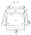
- FIG. 20 a top plan view of the embodiment with the arms added
- FIG. 21 the same view as FIG. 20, showing other adjustments of the arm rests.
- FIG. 22 a front elevational view of the embodiment with arms added.
- the embodiment has a five-legged caster base 10 , a gas spring column 12 , which is affixed to the base and permits adjustment of the height of the entire chair seat unit (seat bottom assembly 14 and seat back assembly 16 ), and a seat-mounting mechanism 18 mounted on the column, which permits the entire seat unit to tilt forward and backward from an upright position and to be locked in the upright or forward tilted position.
- the seat-mounting mechanism also allows the position of the seat bottom 14 to be adjusted forward and backward, as shown by the small arrow A 1 , and locked in the desired position.
- the components described in this paragraph are well-known and available commercially in various specific designs from numerous vendors of parts for office seating.
- the base for a chair embodying the present invention need not include all of the features described in this paragraph.
- the seat back assembly 16 includes right and left seat back support mounting members 20 r and 20 l , which are joined to each other near their lower ends by a pair of structural cross-members 22 and 24 (see FIGS. 5 and 7 ).
- the cross-members 22 and 24 are affixed to a plate 26 that is part of a seat back height-adjusting unit 28 that is located in the center and to the rear of the seat-mounting mechanism 18 and permits the height of the seat back assembly 16 to be adjusted, as indicated by the arrow A 2 and the phantom lines in FIG. 1, and locked in a desired position.
- the other component 30 shown schematically in FIGS.
- Height-adjusting units 28 suitable for use in a chair according to the present invention are well-known and available commercially from various sources.
- the back support mounting members 20 r and 20 l are steel tubes that are bent to be bowed in lateral profile (FIG. 1) and also to slope outwardly in an upward direction from points at about waist level in front plan (FIG. 2 ).
- a lower back support 40 is mounted on the back support mounting members 20 r and 20 l for pivotal movement, as indicated by the arrows A 3 and the phantom lines in FIG. 1, about a transverse horizontal axis LA located substantially at the vertical centerline of the lower back support 40 .
- An upper back support 42 is mounted on the back support mounting members 20 r and 20 l for pivotal movement, as indicated by the arrows A 4 and the phantom lines in FIG.
- Each back support 40 and 42 includes a structural pan 40 p , 42 p , which may be stamped from metal sheet or molded from a plastic, an upholstered pad 40 u , 42 u , and a molded plastic rear cover 40 c , 42 c .
- the back supports 40 and 42 are generally rectangular in front plan (FIG. 2) and have their side edges located closely adjacent the back support mounting members 20 r and 20 l , which are located abreast of the back supports.
- the upper edge of the lower back support 40 lies closely adjacent the lower edge of the upper back support 42 .
- the concepts here are to maximize the sizes of the two back supports for good support of the chair occupant with low pressure applied to the occupant's back for any given load and to avoid discontinuities in the vertical direction.
- the two back supports are also contoured both horizontally and vertically to present forward surfaces that match generally the anatomical shape of the human back both vertically and horizontally.
- each resilient mount unit 50 is affixed to the structural pan 40 p , 42 p of the back support and to the back support mounting member 20 r , 20 l and includes an elastomeric member 52 , a first support plate 54 affixed to one side of the elastomeric member and to the structural pan, and a second support plate 56 affixed to the other side of the elastomeric member.
- a screw 58 affixes a mounting bracket 60 to the second support plate 56 .
- the structural pan 40 p , 42 p includes a recess cavity 40 r , 42 r that accepts the first support plate and a portion of the elastomeric member.
- the mounting bracket 60 includes a mounting post 60 p that passes through a hole in the near side wall of the back support mounting member 20 r , 20 l and is joined to the opposite side wall of the back support mounting member by a weldment 62 at a weld site that includes a hole in the opposite side wall.
- each back support 40 , 42 form a back support sub-assembly.
- the brackets 60 are assembled to the back support mounting members 20 r and 20 l as part of the assembly of the frame (back support mounting members 20 r and 20 l and cross members 22 ) of the seat back assembly 16 .
- Each back support subassembly is then assembled to the brackets 50 and secured by the screws 58 .
- the covers 40 c , 42 c are then installed and secured in any suitable manner on the upper back support 42 and lower back support 40 .
- Resilient mount units of other constructions may be used in a chair embodying the present invention to mount the back supports 40 , 42 on the back support mounting members 20 r , 20 l .
- the unit 150 of the upper back support 42 includes at each side a bracket 152 , consisting of a plate 152 p and a tube 152 t welded to the plate.
- the plate is fastened by screws to the pan 42 p of the back support 42 .
- the tube 152 t is rotatably received on a pivot pin 60 p that is welded to the back support mounting member (e.g., 20 r ).
- a bent end portion 154 e of a torsion rod 154 is received in a spring coupling fitting 156 .
- the bent portion 154 e passes obliquely to the axis of the coupling fitting 156 through a slot 156 s and is thereby affixed to the coupling tube 156 against rotation.
- the coupling fitting 156 is coupled against rotation to the pivot pin 160 p by a rib and slot coupling 158 (FIG. 10 ).
- the bent end 154 e of the torsion rod 154 is fixed against rotation relative to the pivot pin 60 p.
- the torsion rod 154 extends across the entire width of the back support 42 .
- the other end of the torsion rod 154 (not shown) is linked to the other back support mounting member 20 l .
- a “U” bend 154 u in the center of the torsion rod 154 is clamped to the pan 42 p by a clamp 170 .
- the back support In the relaxed state of the torsion rod 154 , the back support is held in neutral position.
- the U bend 154 u is rotated, thus placing the torsion rod under load.
- the energy stored in the torsion rod returns the back support to the neutral position whenever no force tending to pivot it about the axis of the pivot pin 160 p is applied to it.
- the mount unit 150 L for the lower back support 40 is the same as the mount unit 150 for the upper back support 42 except for size and shape.
- the space between the lower portions of the back support mounting members 20 r and 20 l and below the lower back support 40 is filled by a lower back panel 70 , which includes a pan 70 p , a rear cover 70 c and upholstered padding 70 u .
- the lower back panel 70 conceals the rear aspect of the mounting unit and the cross members 24 that connect the back support mounting members 20 r and 20 l and imparts a handsome appearance to the rear aspect of the chair (see FIG. 3 ).
- the lower back panel 70 also fills what would otherwise be a gap between the lower edge of the lower back support 40 and the seat bottom 14 (see FIG. 2 ).
- the seat bottom 14 includes a main body portion 14 b and a tilting front portion 14 f , which is attached to the front edge of the body portion to articulate downwardly, as indicated by the arrows A 5 and the phantom lines in FIG. 1 .
- the tilting front portion 14 f is normally held resiliently in the position shown in solid lines by a resilient mount arrangement (examples described below).
- the tilting front portion 14 f tilts down when the forward parts of the undersides of the user's thighs apply a force to it, thus limiting the pressure on the undersides of the user's thighs to the extent of the resilient force exerted by the mount arrangement.
- a seat latch (examples described below) may be included to hold the tilting seat portion in the normal “up” position, or the tilted down position, or both.
- a pair of hinges 80 are affixed to the structural pans of the main seat bottom 14 b and the front seat bottom 14 f .
- a spring housing 82 affixed to the underside of the pan of the main seat bottom receives a compression coil spring 84 , which is compressed under a predetermined load between an end closure 82 e of the housing 82 and a link 85 , a rear portion of which is slidably received in the housing 82 .
- the link 85 is coupled by a pin 86 to a slot cam fitting 88 affixed to the underside of the pan of the front seat bottom 14 f .
- the spring 84 acting through the link 85 and fitting 88 , biases the front seat part to an “up” position but yields when the spring force is exceeded so that the front seat bottom can tilt down and relieve the pressure on the underside of the thighs of a person sitting in the chair.
- Some users may find the tilting movement of the front seat bottom disconcerting. If so, they may engage a latch pin 90 in either one of two latch holes 90 u and 90 d in the link 85 by pushing in an operating handle 92 (see FIG. 13 ). In the position shown in FIG. 13, the front seat bottom 14 f is latched in the “up” position. When the pin 90 is located in the hole 90 d , the front seat bottom is latched in the “down” position. When the pin 90 is retracted, the front seat bottom tilts up and down, depending on the load exerted on it by the user's thighs.
- FIGS. 15 to 18 Another mount arrangement, as shown in FIGS. 15 to 18 , uses elastic bands 100 near each side of the seat bottom to bias the front seat bottom 14 f to the up position.
- the bands 100 are fastened with preloads by tacks or screws to molded plywood bases of the main seat bottom 14 b and front seat bottom 14 f , leaving a length of the bands 100 clear between the closest fasteners to allow stretching of the bands sufficient to accommodate the desired amount of downward tilting of the front seat bottom.
- a latch bar 102 slidably mounted on a carrier 104 affixed to the underside of the main seat bottom 14 b is engageable in a socket 106 of a latch bar receiver 108 affixed to the underside of the front seat bottom.
- An easily accessible operating lever 110 linked to the latch bar by a pin and cam slot 110 p-s (FIG. 17) and pivotally mounted on the carrier 104 by a pivot pin 111 facilitates movement of the latch bar 102 between the latched position (FIG. 15 ), in which the front seat bottom cannot tilt down, and the unlatched position (FIG. 16 ).
- Arms 120 of any suitable design can, if desired, be affixed to the seat-mounting mechanism 18 or the underside of the seat bottom 14 , as shown in FIGS. 19 to 21 .
- Telescoping arrangements of arm support tubes 122 , 124 and 126 and suitable locking devices (not shown) between the telescoping tubes enable adjustments of the heights and fore-aft positions of the arms (arrow AG, FIG. 19 ), angles of the arms to the fore-aft centerline (arrows A 7 , FIG. 20 ), and lateral spacing of the arms (arrows A 7 , FIGS. 21 and 22) to fit the chair optimally to the size of the user.
Landscapes
- Health & Medical Sciences (AREA)
- Organic Chemistry (AREA)
- Chemical & Material Sciences (AREA)
- Pharmacology & Pharmacy (AREA)
- Animal Behavior & Ethology (AREA)
- Life Sciences & Earth Sciences (AREA)
- Chemical Kinetics & Catalysis (AREA)
- General Chemical & Material Sciences (AREA)
- Medicinal Chemistry (AREA)
- Nuclear Medicine, Radiotherapy & Molecular Imaging (AREA)
- Pulmonology (AREA)
- Bioinformatics & Cheminformatics (AREA)
- Engineering & Computer Science (AREA)
- Immunology (AREA)
- General Health & Medical Sciences (AREA)
- Public Health (AREA)
- Veterinary Medicine (AREA)
- Chairs Characterized By Structure (AREA)
- Chair Legs, Seat Parts, And Backrests (AREA)
- Special Chairs (AREA)
- Acyclic And Carbocyclic Compounds In Medicinal Compositions (AREA)
- Finger-Pressure Massage (AREA)
Abstract
A chair has a pair of spaced-apart back support mounting members, a lower back support adapted to support the lower portion of the back of a person seated on the chair and mounted on the back support mounting members for pivotal movement about a pivot axis located at substantially the vertical centerline of the lower back support, and an upper back support adapted to support the upper portion of the back of a person seated on the chair and mounted on the back support mounting members for pivotal movement about a pivot axis located at substantially the vertical centerline of the upper back support.
Description
The rapid development of the “new economy” in recent years has required office workers at all levels to spend ever-increasing amounts of time working at computers. No longer is the use of a keyboard the province of a typist/secretary or word processor operator. Managers frequently communicate by E-mail and access company data and websites for information required for carrying out their duties. Product design and development, purchasing, marketing, production, shipping, and virtually all other activities in industry and commerce are done with the aid of computers. Professionals likewise use computers for obtaining information, communicating, and for creating documents and computer data files.
Sitting upright in a somewhat forward-leaning position to work at a keyboard places considerable strain on the back and is highly fatiguing. Minimizing strain and fatigue requires a chair that provides excellent support for the user's back, not only in a working position but a relaxed position. In that regard, it is also important for reducing strain for persons working at a computer or over papers on a desk to be able to change their positions frequently and to be able to lean back to a rest position from time to time.
Currently available office chairs allow various adjustments that improve seating comfort in working and relaxed postures. For example, seat mounts that allow the entire chair to tilt backward and forward are very common. Some office chairs have back supports that tilt backward relative to the seat bottom or seat bottoms that slide forward and backward relative to the back support, or both. Most typists chairs have a back support that pivots so as to self-adjust to the sitting posture of the user. Office chairs usually have a support column that permits adjustment of the height of the entire seat (bottom and backrest) above the floor. Many typists chairs also provide for adjustment of the height of the back support relative to the seat.
A need that has not, to the present inventor's knowledge, been adequately met by previously known and/or available office chairs is a chair back that provides good support for the entire anatomical back of a user from the sacrum to the shoulders over a range of seating postures. On the one hand, office chairs designed for use by typists have a back support that self-adjusts about a horizontal pivot axis but is relatively small so that it supports only the lower back. Managerial and executive chairs, on the other hand, have large back supports that are of fixed shapes. The anatomical back assumes widely different vertical curvatures, depending on the seating posture. Chair back supports of fixed shapes provide good support in only one seating posture.
One object of the present invention is to provide an office chair that provides optimal support of the entire back of a user in a wide range of sitting postures. Another object is to provide an office chair of relatively simple construction that permits adjustments of the configurations of the back support and the seat bottom to suit ideally users of all heights. It is also desired to make a chair that meets the foregoing objects attractive in appearance.
The foregoing objects are attained, in accordance with the present invention, by a chair that has a pair of spaced-apart back support mounting members, a lower back support adapted to support the lower portion of the back of a person seated on the chair and mounted on the back support mounting members for pivotal movement about a pivot axis located at substantially the vertical centerline of the lower back support, and an upper back support adapted to support the upper portion of the back of a person seated on the chair and mounted on the back support mounting members for pivotal movement about a pivot axis located at substantially the vertical centerline of the upper back support.
The two back support members of the chair of the present invention provide support of a user's back throughout the region from the sacrum to just above the shoulder blades, which relieves strain on the user's back in all sitting postures and also considerably improves the comfort of the chair in all sitting postures, especially in a leaning back posture. The pivoting of the two back supports independently permits each back support to self-adjust to the curvature in the vertical direction of the user's back, which varies considerably over a range of sitting postures. Pressure loads transferred from back supports to the user's back are, by virtue of the pivoting of both back supports, relatively evenly distributed over the user's back.
The lower back support and upper back support are, preferably, mounted on the back support mounting members by resilient mount units that bias the back supports to a predetermined position. The principal function of the resilient mounting of the two back supports is to keep both back supports in a neutral position when the chair is unoccupied so that it looks better and also so that when someone first sits down, the back supports are in proper position to encounter the user's back with relatively even pressure rather than being far out of position and presenting edges of the supports to the user's back. The spring force acting on each back support should, however, be kept low so that there is little effect on the pressure applied to the user's back when the back supports pivot against the resilient bias—i.e., so that a substantially uniform pressure is applied by each back support to the portion of the user's back engaged by the back support.
Each of the resilient mount units may include an elastomeric body affixed to and interposed functionally between the back support and the back support mounting member. Resilient mount units based on elastomeric members, which are known per se and are commercially available, are quiet in operation, relatively inexpensive, small and compact in size, and easy to install. Various mechanical spring systems can also be used.
In preferred embodiments, the back support mounting members are located laterally abreast of the back supports. That relative disposition of the back supports and the back support mounting members has structural and manufacturing advantages. For example, the back supports may be made large in size, both in height and width; by supporting each of them at each side edge at a single pivot point, torsion loads at the mounting points are not a factor in the design. Each back support, preferably, includes a structural pan for maintaining the shape of the back support under load and for transmitting loads laterally outwardly to the back support mounting members and upholstered padding carried by the pan.
Each of the back supports is, in preferred embodiments, generally rectangular, and the side edges of each of the back supports are closely adjacent the back support mounting members. That configuration provides wide back supports, which distribute the loads applied to the user's back over a large area transversely and for any given total load reduce the pressure on the user's back. Similarly, the upper edge of the lower back support is closely adjacent the lower edge of the upper back support. In addition to keeping the back supports large in area for reduced pressure, the lack of a gap between the two back supports improves the comfort by maintaining continuity of support in the vertical direction.
It is desirable that each of the lower back support and the upper back support be transversely curved and present a transversely concave front surface that corresponds in shape generally to the transverse curvature of the anatomical back of a person. Also, the lower back support is vertically curved and presents a vertically curved convex surface that corresponds in shape generally to the vertical curvature of the lower portion of the anatomical back of a person in the region of the small of the back at the waist.
The chair back structure described above is, of course, mounted on a base having a seat mount supporting a seat bottom. The chair back structure is, preferably, mounted on a back support bracket associated with the seat mount. The back support mounting members are, in preferred embodiments, joined by a transverse framework that is supported by the back support bracket for adjustment of the height of the back support mounting members.
According to another aspect of the present invention, a chair according to the present invention has a seat bottom unit having a body part and a front edge part, the rear edge of the front edge part being coupled to the front edge of the body part for downward articulation of the front edge part from a resiliently restrained upward position. The downwardly tilting front part of the seat bottom allows the front part of the seat to tilt down in response to pressure from the undersides of the lower parts of the user's thighs, thus relieving pressure on them. The seat bottom should be mounted on the seat mount for adjustment forwardly and rearwardly relative to the seat mount so that the chair can be adjusted to suit ideally the height of the user.
In a particularly advantageous construction of the resilient mount units, a first support plate is affixed to one side of the elastomeric member and to the structural pan. A second support plate is affixed to the other side of the elastomeric member. A mounting bracket is affixed to the back support mounting member, and a screw affixes the mounting bracket to the second support plate. The structural pan includes a cavity receiving the first support plate and a portion of the elastomeric member. Each back support mounting member is a tubular member having side walls, and the mounting bracket includes a mounting post that passes through a hole in one side wall of the back support mounting members and is joined to the opposite side wall of the back support mounting members by a weldment at a weld site that includes a hole in the opposite side wall. One advantage of the foregoing construction is that the mounting bracket is very strongly joined to the back support mounting member by passing through a hole in one wall and being joined to the opposite wall by welding at a weld site formed by a hole in the opposite wall. The hole and the weld form two attachment points for the mounting post to the back support mounting member. If desirable or necessary for torsional strength about the pivot axis, both support points can be welded. Another advantage is that the resilient mount can be virtually completely concealed for good appearance of the chair. Furthermore, assembly of each back support to the back support mounting members is facilitated by having a single screw for attaching the bracket of the resilient mount unit.
For a more complete understanding of the present invention, and the advantages thereof, reference may be made to the following written description of an exemplary embodiment, taken in conjunction with the accompanying drawings, which show the following views of the embodiment:
FIG. 1—a side elevational view;
FIG. 2—a front elevational view;
FIG. 3—a rear elevational view;
FIG. 4—a top plan view;
FIG. 5—a partial, generally schematic side cross-sectional view;
FIG. 6—a partial top cross-sectional view, taken along the lines 6—6 of FIG. 5;
FIG. 7—a partial top cross-sectional view, taken along the lines 7—7 of FIG. 5;
FIG. 8—a partial, generally schematic side cross-sectional view, showing a modified pivot mount for the back support;
FIG. 9—a partial rear elevational view with a portion broken away and showing the modified pivot mount of FIG. 8;
FIG. 10—a partial top cross-sectional view, taken along the lines 10—10 of FIG. 8;
FIG. 11—a detail side elevational view of the front portion of the seat, portions being broken away;
FIG. 12—the same view as FIG. 11, but showing a different position;
FIG. 13—a detail top plan view of a front corner portion of the seat, portions being broken away;
FIG. 14—a front elevational view of a part of the seat, a portion being broken away;
FIG. 15—a detail side elevational view of the front portion of the seat, portions being broken away and a modified support and latch unit being shown;
FIG. 16—the same view as FIG. 15, but showing a different position;
FIG. 17—a detail top plan view of a front corner portion of the seat of FIG. 15, portions being broken away;
FIG. 18—a front elevational view of a part of the seat of FIGS. 15 to 17, a portion being broken away;
FIG. 19—a side elevational view, showing arms attached to the embodiment;
FIG. 20—a top plan view of the embodiment with the arms added;
FIG. 21—the same view as FIG. 20, showing other adjustments of the arm rests; and
FIG. 22—a front elevational view of the embodiment with arms added.
The embodiment has a five-legged caster base 10, a gas spring column 12, which is affixed to the base and permits adjustment of the height of the entire chair seat unit (seat bottom assembly 14 and seat back assembly 16), and a seat-mounting mechanism 18 mounted on the column, which permits the entire seat unit to tilt forward and backward from an upright position and to be locked in the upright or forward tilted position. The seat-mounting mechanism also allows the position of the seat bottom 14 to be adjusted forward and backward, as shown by the small arrow A1, and locked in the desired position. The components described in this paragraph are well-known and available commercially in various specific designs from numerous vendors of parts for office seating. The base for a chair embodying the present invention need not include all of the features described in this paragraph.
The seat back assembly 16 includes right and left seat back support mounting members 20 r and 20 l, which are joined to each other near their lower ends by a pair of structural cross-members 22 and 24 (see FIGS. 5 and 7). The cross-members 22 and 24 are affixed to a plate 26 that is part of a seat back height-adjusting unit 28 that is located in the center and to the rear of the seat-mounting mechanism 18 and permits the height of the seat back assembly 16 to be adjusted, as indicated by the arrow A2 and the phantom lines in FIG. 1, and locked in a desired position. The other component 30 (shown schematically in FIGS. 5 and 7 as a box-like part) of the height-adjusting unit is affixed to a back-mounting bracket 32 that is affixed to the seatmounting mechanism 18. Height-adjusting units 28 suitable for use in a chair according to the present invention are well-known and available commercially from various sources.
The back support mounting members 20 r and 20 l are steel tubes that are bent to be bowed in lateral profile (FIG. 1) and also to slope outwardly in an upward direction from points at about waist level in front plan (FIG. 2). A lower back support 40 is mounted on the back support mounting members 20 r and 20 l for pivotal movement, as indicated by the arrows A3 and the phantom lines in FIG. 1, about a transverse horizontal axis LA located substantially at the vertical centerline of the lower back support 40. An upper back support 42 is mounted on the back support mounting members 20 r and 20 l for pivotal movement, as indicated by the arrows A4 and the phantom lines in FIG. 1, about a transverse horizontal axis UA located substantially at the vertical centerline of the upper back support 42. Each back support 40 and 42 includes a structural pan 40 p, 42 p, which may be stamped from metal sheet or molded from a plastic, an upholstered pad 40 u, 42 u, and a molded plastic rear cover 40 c, 42 c. The back supports 40 and 42 are generally rectangular in front plan (FIG. 2) and have their side edges located closely adjacent the back support mounting members 20 r and 20 l, which are located abreast of the back supports. The upper edge of the lower back support 40 lies closely adjacent the lower edge of the upper back support 42. The concepts here are to maximize the sizes of the two back supports for good support of the chair occupant with low pressure applied to the occupant's back for any given load and to avoid discontinuities in the vertical direction. The two back supports are also contoured both horizontally and vertically to present forward surfaces that match generally the anatomical shape of the human back both vertically and horizontally.
The upper back support 42 and lower back support 40 are mounted on the left and right back support mounting members 20 r and 20 ls by identical resilient mount units 50, one on each side. Referring to FIG. 6, each resilient mount unit 50 is affixed to the structural pan 40 p, 42 p of the back support and to the back support mounting member 20 r, 20 l and includes an elastomeric member 52, a first support plate 54 affixed to one side of the elastomeric member and to the structural pan, and a second support plate 56 affixed to the other side of the elastomeric member. A screw 58 affixes a mounting bracket 60 to the second support plate 56. The structural pan 40 p, 42 p includes a recess cavity 40 r, 42 r that accepts the first support plate and a portion of the elastomeric member. The mounting bracket 60 includes a mounting post 60 p that passes through a hole in the near side wall of the back support mounting member 20 r, 20 l and is joined to the opposite side wall of the back support mounting member by a weldment 62 at a weld site that includes a hole in the opposite side wall.
The pan 40 p, 42 p, upholstered pad 40 u, 42 u, and the elastomeric member 52, with its support plates 54 and 56, of each back support 40, 42 form a back support sub-assembly. The brackets 60 are assembled to the back support mounting members 20 r and 20 l as part of the assembly of the frame (back support mounting members 20 r and 20 l and cross members 22) of the seat back assembly 16. Each back support subassembly is then assembled to the brackets 50 and secured by the screws 58. The covers 40 c, 42 c are then installed and secured in any suitable manner on the upper back support 42 and lower back support 40.
Resilient mount units of other constructions, such as the resilient mount unit 150 shown in FIGS. 8 to 10, may be used in a chair embodying the present invention to mount the back supports 40, 42 on the back support mounting members 20 r, 20 l. The unit 150 of the upper back support 42 includes at each side a bracket 152, consisting of a plate 152 p and a tube 152 t welded to the plate. The plate is fastened by screws to the pan 42 p of the back support 42. The tube 152 t is rotatably received on a pivot pin 60 p that is welded to the back support mounting member (e.g., 20 r). A bent end portion 154 e of a torsion rod 154 is received in a spring coupling fitting 156. The bent portion 154 e passes obliquely to the axis of the coupling fitting 156 through a slot 156 s and is thereby affixed to the coupling tube 156 against rotation. The coupling fitting 156 is coupled against rotation to the pivot pin 160 p by a rib and slot coupling 158 (FIG. 10). Thus, the bent end 154 e of the torsion rod 154 is fixed against rotation relative to the pivot pin 60 p.
The torsion rod 154 extends across the entire width of the back support 42. The other end of the torsion rod 154 (not shown) is linked to the other back support mounting member 20 l. A “U” bend 154 u in the center of the torsion rod 154 is clamped to the pan 42 p by a clamp 170. In the relaxed state of the torsion rod 154, the back support is held in neutral position. When a person sitting in the chair changes his sitting posture such as to apply a force to the back support 42 tending to tilt it in either direction from the neutral position (see arrows A3), the U bend 154 u is rotated, thus placing the torsion rod under load. The energy stored in the torsion rod returns the back support to the neutral position whenever no force tending to pivot it about the axis of the pivot pin 160 p is applied to it.
The mount unit 150L for the lower back support 40 is the same as the mount unit 150 for the upper back support 42 except for size and shape.
The space between the lower portions of the back support mounting members 20 r and 20 l and below the lower back support 40 is filled by a lower back panel 70, which includes a pan 70 p, a rear cover 70 c and upholstered padding 70 u. The lower back panel 70 conceals the rear aspect of the mounting unit and the cross members 24 that connect the back support mounting members 20 r and 20 l and imparts a handsome appearance to the rear aspect of the chair (see FIG. 3). The lower back panel 70 also fills what would otherwise be a gap between the lower edge of the lower back support 40 and the seat bottom 14 (see FIG. 2).
As shown in, for example, FIGS. 1 and 4, the seat bottom 14 includes a main body portion 14 b and a tilting front portion 14 f, which is attached to the front edge of the body portion to articulate downwardly, as indicated by the arrows A5 and the phantom lines in FIG. 1. The tilting front portion 14 f is normally held resiliently in the position shown in solid lines by a resilient mount arrangement (examples described below). The tilting front portion 14 f tilts down when the forward parts of the undersides of the user's thighs apply a force to it, thus limiting the pressure on the undersides of the user's thighs to the extent of the resilient force exerted by the mount arrangement. A seat latch (examples described below) may be included to hold the tilting seat portion in the normal “up” position, or the tilted down position, or both.
In one mount arrangement, as shown in FIGS. 11 to 14, a pair of hinges 80, one near each side edge of the seat bottom 14, are affixed to the structural pans of the main seat bottom 14 b and the front seat bottom 14 f. A spring housing 82 affixed to the underside of the pan of the main seat bottom receives a compression coil spring 84, which is compressed under a predetermined load between an end closure 82 e of the housing 82 and a link 85, a rear portion of which is slidably received in the housing 82. The link 85 is coupled by a pin 86 to a slot cam fitting 88 affixed to the underside of the pan of the front seat bottom 14 f. The spring 84, acting through the link 85 and fitting 88, biases the front seat part to an “up” position but yields when the spring force is exceeded so that the front seat bottom can tilt down and relieve the pressure on the underside of the thighs of a person sitting in the chair.
Some users may find the tilting movement of the front seat bottom disconcerting. If so, they may engage a latch pin 90 in either one of two latch holes 90 u and 90 d in the link 85 by pushing in an operating handle 92 (see FIG. 13). In the position shown in FIG. 13, the front seat bottom 14 f is latched in the “up” position. When the pin 90 is located in the hole 90 d, the front seat bottom is latched in the “down” position. When the pin 90 is retracted, the front seat bottom tilts up and down, depending on the load exerted on it by the user's thighs.
Another mount arrangement, as shown in FIGS. 15 to 18, uses elastic bands 100 near each side of the seat bottom to bias the front seat bottom 14 f to the up position. The bands 100 are fastened with preloads by tacks or screws to molded plywood bases of the main seat bottom 14 b and front seat bottom 14 f, leaving a length of the bands 100 clear between the closest fasteners to allow stretching of the bands sufficient to accommodate the desired amount of downward tilting of the front seat bottom. A latch bar 102 slidably mounted on a carrier 104 affixed to the underside of the main seat bottom 14 b is engageable in a socket 106 of a latch bar receiver 108 affixed to the underside of the front seat bottom. An easily accessible operating lever 110 linked to the latch bar by a pin and cam slot 110 p-s (FIG. 17) and pivotally mounted on the carrier 104 by a pivot pin 111 facilitates movement of the latch bar 102 between the latched position (FIG. 15), in which the front seat bottom cannot tilt down, and the unlatched position (FIG. 16).
Telescoping arrangements of arm support tubes 122, 124 and 126 and suitable locking devices (not shown) between the telescoping tubes enable adjustments of the heights and fore-aft positions of the arms (arrow AG, FIG. 19), angles of the arms to the fore-aft centerline (arrows A7, FIG. 20), and lateral spacing of the arms (arrows A7, FIGS. 21 and 22) to fit the chair optimally to the size of the user.
Claims (19)
1. A chair comprising
a frame having a pair of spaced-apart stationary back support mounting members,
a lower back support adapted to support the dorsal portion of the back of a person seated on the chair,
lower resilient mount units mounting the lower back support directly on the back support mounting members for pivotal movement about a horizontal pivot axis located at substantially the vertical center of the lower back support and biasing the lower back support to a predetermined position,
an upper back support adapted to support the upper portion of the back of a person seated on the chair, and
upper resilient mount units mounting the upper back support directly on the back support mounting members for pivotal movement about a horizontal pivot axis located at substantially the vertical center of the upper back support and biasing the upper back support to a predetermined position,
the back supports being configured to provide support for the user's back throughout the region from the sacrum to just above the shoulders.
2. The chair according to claim 1 , wherein each of the resilient mount units includes an elastomeric body affixed to and interposed functionally between the back support and the back support mounting member.
3. The chair according to claim 1 , wherein the back support mounting members are located laterally abreast of the back supports.
4. The chair according to claim 1 , wherein each back support includes a structural pan and upholstered padding carried by the pan.
5. The chair according to claim 1 , wherein each of the back supports is generally rectangular and the side edges of each of the back supports are closely adjacent to the back support mounting members.
6. The chair according to claim 1 , wherein the upper edge of the lower back support is closely adjacent to the lower edge of the upper back support.
7. The chair according to claim 1 , wherein each of the lower back support and the upper back support is transversely curved and presents a transversely concave front surface that corresponds in shape generally to the transverse curvature of the anatomical back of a person.
8. The chair according to claim 7 , wherein the lower back support is vertically curved and presents a vertically curved convex surface that corresponds in shape generally to the vertical curvature of the dorsal portion of the anatomical back of a person.
9. The chair according to claim 1 , and further comprising a base having a seat mount that includes a back support bracket, and wherein the back support mounting members are joined by a transverse framework that is supported by the back support bracket for adjustment of the height of the back support mounting members.
10. The chair according to claim 1 , and further comprising a seat bottom unit having a main part and a front part, the rear edge of the front part being coupled to the front edge of the main part for articulation of the front part relative to the main part between a resiliently restrained up position and a tilted down position.
11. The chair according to claim 10 , and further comprising a latch for affixing the front part in the up position.
12. The chair according to claim 10 , and further comprising a latch for affixing the front part in the down position.
13. The chair according to claim 10 , and further comprising a base having a seat mount and wherein the seat bottom unit is mounted on the seat mount for adjustment forwardly and rearwardly relative to the seat mount.
14. The chair according to claim 1 , wherein the back support mounting members are located laterally abreast of the back supports, each of the back supports is generally rectangular, the side edges of each of the back supports are closely adjacent to the back support mounting members, and the upper edge of the lower back support is closely adjacent to the lower edge of the upper back support.
15. The chair according to claim 14 , wherein each back support includes a structural pan and upholstered padding carried by the pan.
16. The chair according to claim 15 , wherein each of the resilient mount units includes an elastomeric body affixed to the structural pan of the back support and the back support mounting member.
17. The chair according to claim 16 , wherein each of the resilient mount units further includes a first support plate affixed to one side of the elastomeric member and to the structural pan, a second support plate affixed to the other side of the elastomeric member, a mounting bracket affixed to the back support mounting members, and a screw affixing the mounting bracket to the second support plate.
18. The chair according to claim 17 , wherein the structural pan includes a cavity receiving the first support plate and a portion of the elastomeric member.
19. The chair according to claim 18 , wherein each back support mounting member is tubular and has side walls, and the mounting bracket includes a mounting post that passes through a hole in one side wall of the back support mounting member and is joined to the opposite side wall of the back support mounting member by a weldment at a weld site that includes a hole in the opposite side wall.
Priority Applications (13)
| Application Number | Priority Date | Filing Date | Title |
|---|---|---|---|
| US09/589,332 US6478379B1 (en) | 2000-06-07 | 2000-06-07 | Chair |
| PCT/EP2001/006391 WO2001093907A1 (en) | 2000-06-07 | 2001-06-06 | Chair |
| CNB018107583A CN100377679C (en) | 2000-06-07 | 2001-06-06 | Chair |
| DE60110410T DE60110410T2 (en) | 2000-06-07 | 2001-06-06 | CHAIR |
| ES01938249T ES2240462T3 (en) | 2000-06-07 | 2001-06-06 | CHAIR. |
| CA002410341A CA2410341C (en) | 2000-06-07 | 2001-06-06 | Chair |
| DK01938249T DK1286609T3 (en) | 2000-06-07 | 2001-06-06 | Chair |
| AT01938249T ATE293910T1 (en) | 2000-06-07 | 2001-06-06 | CHAIR |
| PT01938249T PT1286609E (en) | 2000-06-07 | 2001-06-06 | CHAIR |
| AU2001263950A AU2001263950A1 (en) | 2000-06-07 | 2001-06-06 | Chair |
| EP01938249A EP1286609B1 (en) | 2000-06-07 | 2001-06-06 | Chair |
| JP2002501478A JP2003534876A (en) | 2000-06-07 | 2001-06-06 | Chair |
| HK03103143A HK1050826A1 (en) | 2000-06-07 | 2003-05-02 | Chair. |
Applications Claiming Priority (1)
| Application Number | Priority Date | Filing Date | Title |
|---|---|---|---|
| US09/589,332 US6478379B1 (en) | 2000-06-07 | 2000-06-07 | Chair |
Publications (1)
| Publication Number | Publication Date |
|---|---|
| US6478379B1 true US6478379B1 (en) | 2002-11-12 |
Family
ID=24357577
Family Applications (1)
| Application Number | Title | Priority Date | Filing Date |
|---|---|---|---|
| US09/589,332 Expired - Fee Related US6478379B1 (en) | 2000-06-07 | 2000-06-07 | Chair |
Country Status (13)
| Country | Link |
|---|---|
| US (1) | US6478379B1 (en) |
| EP (1) | EP1286609B1 (en) |
| JP (1) | JP2003534876A (en) |
| CN (1) | CN100377679C (en) |
| AT (1) | ATE293910T1 (en) |
| AU (1) | AU2001263950A1 (en) |
| CA (1) | CA2410341C (en) |
| DE (1) | DE60110410T2 (en) |
| DK (1) | DK1286609T3 (en) |
| ES (1) | ES2240462T3 (en) |
| HK (1) | HK1050826A1 (en) |
| PT (1) | PT1286609E (en) |
| WO (1) | WO2001093907A1 (en) |
Cited By (25)
| Publication number | Priority date | Publication date | Assignee | Title |
|---|---|---|---|---|
| US6742839B2 (en) * | 2001-10-04 | 2004-06-01 | Pro-Cord Spa | Stackable chair |
| US20050035636A1 (en) * | 2003-08-13 | 2005-02-17 | Turner Dennis M. | Chair with pivotable chair back |
| US20050093352A1 (en) * | 2003-09-29 | 2005-05-05 | Kabushiki Kaisha Toyota Chuo Kenkyusho | Seat |
| US6890030B2 (en) | 2001-07-31 | 2005-05-10 | Haworth, Inc. | Chair having a seat with adjustable front edge |
| US20050146195A1 (en) * | 2003-12-30 | 2005-07-07 | Machael Jay R. | Chair back rest with improved resilience and support |
| US20060058678A1 (en) * | 2004-08-26 | 2006-03-16 | Insightec - Image Guided Treatment Ltd. | Focused ultrasound system for surrounding a body tissue mass |
| US20070252421A1 (en) * | 2004-06-09 | 2007-11-01 | Otto Zapf | Vehicle Seat |
| US20080067850A1 (en) * | 2006-09-19 | 2008-03-20 | Permobil Ab | Backrest for a chair |
| US20090085388A1 (en) * | 2006-10-04 | 2009-04-02 | Formay Furniture Limited | Chair |
| US20100164266A1 (en) * | 2008-12-29 | 2010-07-01 | L & P Property Management Company | Seat with independently adjustable user support assemblies |
| US20100187881A1 (en) * | 2007-05-22 | 2010-07-29 | Delta Tooling Co., Ltd | Seat structure |
| US20100264709A1 (en) * | 2009-04-16 | 2010-10-21 | Steven Pearse | Back extension backrest |
| DE102009020659A1 (en) * | 2009-05-08 | 2010-11-18 | Audi Ag | Vehicle seat, has seat front part pivoted between upper end position and lower end position corresponding to protection and loading positions, and seat front part provided with spring element in direction on upper end position |
| USD637423S1 (en) | 2010-04-13 | 2011-05-10 | Herman Miller, Inc. | Chair |
| USD639091S1 (en) | 2010-04-13 | 2011-06-07 | Herman Miller, Inc. | Backrest |
| USD650206S1 (en) | 2010-04-13 | 2011-12-13 | Herman Miller, Inc. | Chair |
| USD652657S1 (en) | 2010-04-13 | 2012-01-24 | Herman Miller, Inc. | Chair |
| USD653061S1 (en) | 2010-04-13 | 2012-01-31 | Herman Miller, Inc. | Chair |
| USD657166S1 (en) | 2010-04-13 | 2012-04-10 | Herman Miller, Inc. | Chair |
| US8449037B2 (en) | 2010-04-13 | 2013-05-28 | Herman Miller, Inc. | Seating structure with a contoured flexible backrest |
| US20130175838A1 (en) * | 2010-10-01 | 2013-07-11 | Nissan Motor Co., Ltd. | Vehicle seat and stiffness setting method for vehicle seat |
| US20130214577A1 (en) * | 2010-05-18 | 2013-08-22 | Aria Enterprises, Inc. | Portable, compact folding furniture pieces |
| US20160235203A1 (en) * | 2015-02-12 | 2016-08-18 | Wilkhahn Wilkening + Hahne Gmbh + Co. | Seating furniture product |
| US20190343287A1 (en) * | 2018-05-11 | 2019-11-14 | Hangzhou Zhongtai Industrial Group Co., Ltd. | Slider-crank mechanism adjustment type swivel chair tray |
| US20210177149A1 (en) * | 2017-06-09 | 2021-06-17 | Steelcase Inc. | Seating arrangement and method of construction |
Families Citing this family (7)
| Publication number | Priority date | Publication date | Assignee | Title |
|---|---|---|---|---|
| AU2005244822B2 (en) | 2004-05-13 | 2012-03-15 | Humanscale Corporation | Mesh chair component |
| US8061775B2 (en) | 2005-06-20 | 2011-11-22 | Humanscale Corporation | Seating apparatus with reclining movement |
| WO2008018117A1 (en) * | 2006-08-07 | 2008-02-14 | Itoki Corporation | Chair |
| US9504326B1 (en) | 2012-04-10 | 2016-11-29 | Humanscale Corporation | Reclining chair |
| JP6920156B2 (en) * | 2017-09-28 | 2021-08-18 | 株式会社オカムラ | Chair |
| DE102018200024A1 (en) * | 2018-01-02 | 2019-07-04 | Ford Global Technologies, Llc | Adjustable thigh support for a vehicle seat |
| DE102022105298A1 (en) | 2022-03-07 | 2023-09-07 | Bayerische Motoren Werke Aktiengesellschaft | motor vehicle seat |
Citations (10)
| Publication number | Priority date | Publication date | Assignee | Title |
|---|---|---|---|---|
| US590045A (en) | 1897-09-14 | mauchain | ||
| US1720794A (en) | 1925-03-21 | 1929-07-16 | Simmons Co | Chair back |
| US2098456A (en) | 1935-05-20 | 1937-11-09 | American Seating Co | Seat back |
| GB680854A (en) * | 1950-07-20 | 1952-10-15 | Tan Sad Chair Co 1931 Ltd | Improvements relating to the pivotal backs of chairs and the like |
| US3540777A (en) | 1967-12-02 | 1970-11-17 | Mario Revelli De Beaumont | Chair for automotive vehicles with a displaceable back |
| US4768833A (en) | 1986-07-10 | 1988-09-06 | Virco Mfg. Corporation | Chair construction |
| US5100201A (en) | 1990-09-21 | 1992-03-31 | J.G. Furniture Systems Inc. | Passive ergonomic work chair |
| US5120109A (en) | 1988-07-25 | 1992-06-09 | Sicam S.P.A. | Motor vehicle seat |
| US5447356A (en) | 1990-05-01 | 1995-09-05 | B.V. Linido | Chair for disabled persons |
| US5597203A (en) | 1994-06-14 | 1997-01-28 | Board Of Trustees Operating Michigan State University | Seat with biomechanical articulation |
Family Cites Families (1)
| Publication number | Priority date | Publication date | Assignee | Title |
|---|---|---|---|---|
| CN87205596U (en) * | 1987-03-24 | 1988-01-13 | 刘恭信 | Multipurpose-dual-turning chair |
-
2000
- 2000-06-07 US US09/589,332 patent/US6478379B1/en not_active Expired - Fee Related
-
2001
- 2001-06-06 AT AT01938249T patent/ATE293910T1/en not_active IP Right Cessation
- 2001-06-06 CA CA002410341A patent/CA2410341C/en not_active Expired - Fee Related
- 2001-06-06 CN CNB018107583A patent/CN100377679C/en not_active Expired - Fee Related
- 2001-06-06 PT PT01938249T patent/PT1286609E/en unknown
- 2001-06-06 AU AU2001263950A patent/AU2001263950A1/en not_active Abandoned
- 2001-06-06 ES ES01938249T patent/ES2240462T3/en not_active Expired - Lifetime
- 2001-06-06 DK DK01938249T patent/DK1286609T3/en active
- 2001-06-06 WO PCT/EP2001/006391 patent/WO2001093907A1/en active IP Right Grant
- 2001-06-06 EP EP01938249A patent/EP1286609B1/en not_active Expired - Lifetime
- 2001-06-06 DE DE60110410T patent/DE60110410T2/en not_active Expired - Fee Related
- 2001-06-06 JP JP2002501478A patent/JP2003534876A/en active Pending
-
2003
- 2003-05-02 HK HK03103143A patent/HK1050826A1/en not_active IP Right Cessation
Patent Citations (10)
| Publication number | Priority date | Publication date | Assignee | Title |
|---|---|---|---|---|
| US590045A (en) | 1897-09-14 | mauchain | ||
| US1720794A (en) | 1925-03-21 | 1929-07-16 | Simmons Co | Chair back |
| US2098456A (en) | 1935-05-20 | 1937-11-09 | American Seating Co | Seat back |
| GB680854A (en) * | 1950-07-20 | 1952-10-15 | Tan Sad Chair Co 1931 Ltd | Improvements relating to the pivotal backs of chairs and the like |
| US3540777A (en) | 1967-12-02 | 1970-11-17 | Mario Revelli De Beaumont | Chair for automotive vehicles with a displaceable back |
| US4768833A (en) | 1986-07-10 | 1988-09-06 | Virco Mfg. Corporation | Chair construction |
| US5120109A (en) | 1988-07-25 | 1992-06-09 | Sicam S.P.A. | Motor vehicle seat |
| US5447356A (en) | 1990-05-01 | 1995-09-05 | B.V. Linido | Chair for disabled persons |
| US5100201A (en) | 1990-09-21 | 1992-03-31 | J.G. Furniture Systems Inc. | Passive ergonomic work chair |
| US5597203A (en) | 1994-06-14 | 1997-01-28 | Board Of Trustees Operating Michigan State University | Seat with biomechanical articulation |
Cited By (44)
| Publication number | Priority date | Publication date | Assignee | Title |
|---|---|---|---|---|
| US6890030B2 (en) | 2001-07-31 | 2005-05-10 | Haworth, Inc. | Chair having a seat with adjustable front edge |
| US6742839B2 (en) * | 2001-10-04 | 2004-06-01 | Pro-Cord Spa | Stackable chair |
| US20050035636A1 (en) * | 2003-08-13 | 2005-02-17 | Turner Dennis M. | Chair with pivotable chair back |
| US6974188B2 (en) * | 2003-08-13 | 2005-12-13 | Cosco Management, Inc. | Chair with pivotable chair back |
| US20050093352A1 (en) * | 2003-09-29 | 2005-05-05 | Kabushiki Kaisha Toyota Chuo Kenkyusho | Seat |
| US7104607B2 (en) * | 2003-09-29 | 2006-09-12 | Kabushiki Kaisha Toyota Chuo Kenkyusho | Seat |
| US20050146195A1 (en) * | 2003-12-30 | 2005-07-07 | Machael Jay R. | Chair back rest with improved resilience and support |
| US8157325B2 (en) * | 2003-12-30 | 2012-04-17 | Hni Technologies Inc. | Chair back rest with improved resilience and support |
| US20070252421A1 (en) * | 2004-06-09 | 2007-11-01 | Otto Zapf | Vehicle Seat |
| US7445288B2 (en) * | 2004-06-09 | 2008-11-04 | Otto Zapf | Vehicle seat |
| US20060058678A1 (en) * | 2004-08-26 | 2006-03-16 | Insightec - Image Guided Treatment Ltd. | Focused ultrasound system for surrounding a body tissue mass |
| US20080067850A1 (en) * | 2006-09-19 | 2008-03-20 | Permobil Ab | Backrest for a chair |
| US8087727B2 (en) | 2006-10-04 | 2012-01-03 | Formway Furniture Limited | Chair |
| US20090085388A1 (en) * | 2006-10-04 | 2009-04-02 | Formay Furniture Limited | Chair |
| US8888183B2 (en) | 2006-10-04 | 2014-11-18 | Formway Furniture Limited | Chair |
| US8668265B2 (en) | 2006-10-04 | 2014-03-11 | Formway Furniture Limited | Chair |
| US8613481B2 (en) | 2006-10-04 | 2013-12-24 | Formway Furniture Limited | Chair |
| US8096615B2 (en) * | 2006-10-04 | 2012-01-17 | Formay Furniture Limited | Chair |
| US20090218864A1 (en) * | 2006-10-04 | 2009-09-03 | Formway Furniture Limited | chair |
| US8029060B2 (en) | 2006-10-04 | 2011-10-04 | Formway Furniture Limited | Chair |
| US20100187881A1 (en) * | 2007-05-22 | 2010-07-29 | Delta Tooling Co., Ltd | Seat structure |
| US8540313B2 (en) * | 2007-05-22 | 2013-09-24 | Delta Tooling Co., Ltd. | Seat structure |
| US7967379B2 (en) | 2008-12-29 | 2011-06-28 | L&P Property Management Company | Seat with independently adjustable user support assemblies |
| US20100164266A1 (en) * | 2008-12-29 | 2010-07-01 | L & P Property Management Company | Seat with independently adjustable user support assemblies |
| US20100264709A1 (en) * | 2009-04-16 | 2010-10-21 | Steven Pearse | Back extension backrest |
| DE102009020659A1 (en) * | 2009-05-08 | 2010-11-18 | Audi Ag | Vehicle seat, has seat front part pivoted between upper end position and lower end position corresponding to protection and loading positions, and seat front part provided with spring element in direction on upper end position |
| USD657166S1 (en) | 2010-04-13 | 2012-04-10 | Herman Miller, Inc. | Chair |
| USD650206S1 (en) | 2010-04-13 | 2011-12-13 | Herman Miller, Inc. | Chair |
| US8449037B2 (en) | 2010-04-13 | 2013-05-28 | Herman Miller, Inc. | Seating structure with a contoured flexible backrest |
| US9301615B2 (en) | 2010-04-13 | 2016-04-05 | Herman Miller, Inc. | Seating structure with a contoured flexible backrest |
| USD653061S1 (en) | 2010-04-13 | 2012-01-31 | Herman Miller, Inc. | Chair |
| USD652657S1 (en) | 2010-04-13 | 2012-01-24 | Herman Miller, Inc. | Chair |
| USD637423S1 (en) | 2010-04-13 | 2011-05-10 | Herman Miller, Inc. | Chair |
| USD639091S1 (en) | 2010-04-13 | 2011-06-07 | Herman Miller, Inc. | Backrest |
| US9084476B2 (en) * | 2010-05-18 | 2015-07-21 | Aria Enterprises, Inc. | Portable, compact folding furniture pieces |
| US20130214577A1 (en) * | 2010-05-18 | 2013-08-22 | Aria Enterprises, Inc. | Portable, compact folding furniture pieces |
| US9668570B2 (en) | 2010-05-18 | 2017-06-06 | Aria Enterprises, Inc. | Compact folding furniture pieces |
| US20130175838A1 (en) * | 2010-10-01 | 2013-07-11 | Nissan Motor Co., Ltd. | Vehicle seat and stiffness setting method for vehicle seat |
| US10543764B2 (en) * | 2010-10-01 | 2020-01-28 | Nissan Motor Co., Ltd. | Vehicle seat and stiffness setting method for vehicle seat |
| US20160235203A1 (en) * | 2015-02-12 | 2016-08-18 | Wilkhahn Wilkening + Hahne Gmbh + Co. | Seating furniture product |
| US9700138B2 (en) * | 2015-02-12 | 2017-07-11 | Wilkhahn Wilkening + Hahne Gmbh + Co. | Seating furniture product |
| US20210177149A1 (en) * | 2017-06-09 | 2021-06-17 | Steelcase Inc. | Seating arrangement and method of construction |
| US11825955B2 (en) * | 2017-06-09 | 2023-11-28 | Steelcase Inc. | Seating arrangement and method of construction |
| US20190343287A1 (en) * | 2018-05-11 | 2019-11-14 | Hangzhou Zhongtai Industrial Group Co., Ltd. | Slider-crank mechanism adjustment type swivel chair tray |
Also Published As
| Publication number | Publication date |
|---|---|
| AU2001263950A1 (en) | 2001-12-17 |
| CN100377679C (en) | 2008-04-02 |
| DK1286609T3 (en) | 2005-08-29 |
| CA2410341A1 (en) | 2001-12-13 |
| PT1286609E (en) | 2005-06-30 |
| ES2240462T3 (en) | 2005-10-16 |
| EP1286609B1 (en) | 2005-04-27 |
| ATE293910T1 (en) | 2005-05-15 |
| DE60110410T2 (en) | 2006-02-09 |
| DE60110410D1 (en) | 2005-06-02 |
| EP1286609A1 (en) | 2003-03-05 |
| HK1050826A1 (en) | 2003-07-11 |
| WO2001093907A1 (en) | 2001-12-13 |
| CN1433323A (en) | 2003-07-30 |
| CA2410341C (en) | 2008-12-23 |
| WO2001093907A9 (en) | 2002-03-07 |
| JP2003534876A (en) | 2003-11-25 |
Similar Documents
| Publication | Publication Date | Title |
|---|---|---|
| US6478379B1 (en) | Chair | |
| US7226127B1 (en) | Ergonomic chair backrest | |
| JP4527529B2 (en) | Dynamically balanced seat assembly | |
| US6969116B2 (en) | Chair with backward and forward passive tilt capabilities | |
| US6056363A (en) | Reclining computer chair apparatus | |
| US10383445B2 (en) | Dynamically balanced seat assembly having independently and arcuately movable backrest and method | |
| US5605311A (en) | Upper torso support for a workstation | |
| US20080231091A1 (en) | Table Mount | |
| US8459738B2 (en) | Portable backrest for a person seated sideways on a sofa | |
| JP2000079034A (en) | Chair | |
| JPS5810008A (en) | Chair seat attaching part | |
| US5452937A (en) | Plate for connecting the seat, back and legs, especially for chairs | |
| US4861108A (en) | Auditorium seat | |
| JPS63317104A (en) | Sitting furniture | |
| EP0941679B1 (en) | Rocking and gliding mechanism | |
| US4345733A (en) | Mounting device for a chair seat | |
| US10470574B2 (en) | Chair having synchronized backrest and seat movements | |
| JP3080585B2 (en) | Chair | |
| JP2000023778A (en) | Chair | |
| KR200340269Y1 (en) | Tilting structure for student chair | |
| US6517159B1 (en) | Support assembly for a forwardly declined armrest | |
| JP2538278Y2 (en) | Chair | |
| JP7173778B2 (en) | Chair | |
| JP3075832U (en) | Front and rear tilting device for chair seat | |
| KR0140441Y1 (en) | Chair |
Legal Events
| Date | Code | Title | Description |
|---|---|---|---|
| AS | Assignment |
Owner name: CENTER FOR DESIGN RESEARCH AND DEVELOPMENT N.V., N Free format text: ASSIGNMENT OF ASSIGNORS INTEREST;ASSIGNOR:AMBASZ, EMILIO;REEL/FRAME:010858/0668 Effective date: 20000602 |
|
| CC | Certificate of correction | ||
| FPAY | Fee payment |
Year of fee payment: 4 |
|
| SULP | Surcharge for late payment | ||
| REMI | Maintenance fee reminder mailed | ||
| LAPS | Lapse for failure to pay maintenance fees | ||
| STCH | Information on status: patent discontinuation |
Free format text: PATENT EXPIRED DUE TO NONPAYMENT OF MAINTENANCE FEES UNDER 37 CFR 1.362 |
|
| FP | Lapsed due to failure to pay maintenance fee |
Effective date: 20101112 |