US6480225B1 - Surveillance system and method using personal computer - Google Patents
Surveillance system and method using personal computer Download PDFInfo
- Publication number
- US6480225B1 US6480225B1 US09/257,180 US25718099A US6480225B1 US 6480225 B1 US6480225 B1 US 6480225B1 US 25718099 A US25718099 A US 25718099A US 6480225 B1 US6480225 B1 US 6480225B1
- Authority
- US
- United States
- Prior art keywords
- image
- pixels
- luminance
- captured image
- surveillance
- Prior art date
- Legal status (The legal status is an assumption and is not a legal conclusion. Google has not performed a legal analysis and makes no representation as to the accuracy of the status listed.)
- Expired - Lifetime
Links
Images


Classifications
-
- H—ELECTRICITY
- H04—ELECTRIC COMMUNICATION TECHNIQUE
- H04N—PICTORIAL COMMUNICATION, e.g. TELEVISION
- H04N7/00—Television systems
- H04N7/18—Closed-circuit television [CCTV] systems, i.e. systems in which the video signal is not broadcast
-
- G—PHYSICS
- G08—SIGNALLING
- G08B—SIGNALLING OR CALLING SYSTEMS; ORDER TELEGRAPHS; ALARM SYSTEMS
- G08B13/00—Burglar, theft or intruder alarms
- G08B13/18—Actuation by interference with heat, light, or radiation of shorter wavelength; Actuation by intruding sources of heat, light, or radiation of shorter wavelength
- G08B13/189—Actuation by interference with heat, light, or radiation of shorter wavelength; Actuation by intruding sources of heat, light, or radiation of shorter wavelength using passive radiation detection systems
- G08B13/194—Actuation by interference with heat, light, or radiation of shorter wavelength; Actuation by intruding sources of heat, light, or radiation of shorter wavelength using passive radiation detection systems using image scanning and comparing systems
- G08B13/196—Actuation by interference with heat, light, or radiation of shorter wavelength; Actuation by intruding sources of heat, light, or radiation of shorter wavelength using passive radiation detection systems using image scanning and comparing systems using television cameras
- G08B13/19602—Image analysis to detect motion of the intruder, e.g. by frame subtraction
-
- G—PHYSICS
- G08—SIGNALLING
- G08B—SIGNALLING OR CALLING SYSTEMS; ORDER TELEGRAPHS; ALARM SYSTEMS
- G08B13/00—Burglar, theft or intruder alarms
- G08B13/18—Actuation by interference with heat, light, or radiation of shorter wavelength; Actuation by intruding sources of heat, light, or radiation of shorter wavelength
- G08B13/189—Actuation by interference with heat, light, or radiation of shorter wavelength; Actuation by intruding sources of heat, light, or radiation of shorter wavelength using passive radiation detection systems
- G08B13/194—Actuation by interference with heat, light, or radiation of shorter wavelength; Actuation by intruding sources of heat, light, or radiation of shorter wavelength using passive radiation detection systems using image scanning and comparing systems
- G08B13/196—Actuation by interference with heat, light, or radiation of shorter wavelength; Actuation by intruding sources of heat, light, or radiation of shorter wavelength using passive radiation detection systems using image scanning and comparing systems using television cameras
- G08B13/19665—Details related to the storage of video surveillance data
- G08B13/19669—Event triggers storage or change of storage policy
-
- G—PHYSICS
- G08—SIGNALLING
- G08B—SIGNALLING OR CALLING SYSTEMS; ORDER TELEGRAPHS; ALARM SYSTEMS
- G08B13/00—Burglar, theft or intruder alarms
- G08B13/18—Actuation by interference with heat, light, or radiation of shorter wavelength; Actuation by intruding sources of heat, light, or radiation of shorter wavelength
- G08B13/189—Actuation by interference with heat, light, or radiation of shorter wavelength; Actuation by intruding sources of heat, light, or radiation of shorter wavelength using passive radiation detection systems
- G08B13/194—Actuation by interference with heat, light, or radiation of shorter wavelength; Actuation by intruding sources of heat, light, or radiation of shorter wavelength using passive radiation detection systems using image scanning and comparing systems
- G08B13/196—Actuation by interference with heat, light, or radiation of shorter wavelength; Actuation by intruding sources of heat, light, or radiation of shorter wavelength using passive radiation detection systems using image scanning and comparing systems using television cameras
- G08B13/19665—Details related to the storage of video surveillance data
- G08B13/19676—Temporary storage, e.g. cyclic memory, buffer storage on pre-alarm
-
- H—ELECTRICITY
- H04—ELECTRIC COMMUNICATION TECHNIQUE
- H04N—PICTORIAL COMMUNICATION, e.g. TELEVISION
- H04N7/00—Television systems
- H04N7/18—Closed-circuit television [CCTV] systems, i.e. systems in which the video signal is not broadcast
- H04N7/183—Closed-circuit television [CCTV] systems, i.e. systems in which the video signal is not broadcast for receiving images from a single remote source
Definitions
- the present invention relates to a surveillance system and method, and more particularly, to a surveillance system and method in which a surrounding area can be observed using a personal computer equipped with a capture board for capturing an image.
- An earlier surveillance system comprises a camera installed in a surveillance area, and a closed circuit television (hereinafter referred to as CCTV) with which a guard observes the surveillance area.
- CCTV closed circuit television
- U.S. Pat. No. 3,825,676 to Ramsden, Jr discloses a Surveillance System using a closed circuit television. Two distinct measurements of a video signal are made. The first measurement is stored. The second measurement is made and compared with the stored measurement. Any difference in excess of a predetermined threshold is indicative of motion of an object within the viewing range. If motion has occurred, an alarm is set off.
- U.S. Pat. No. 5,588,067 for a Motion Detection and Image Acquisition Apparatus and Method of Detecting the Motion of and Acquiring an Image of an Object to Peterson et al discloses a device that compares the current image to the previously saved image and calculates a motion vector. If the motion vector is more than a threshold, the current image is saved on microfiche.
- the prior art does not disclose a pixel by pixel comparison of the luminance differences between a pair of images to determine whether the current image should be saved. Also, there is no indication from the prior art that the time interval between images is adjusted depending on whether or not a current image has just been saved. It is desirable to accomplish these tasks without the use of a video tape recorder so as to save on the amount of equipment used to achieve the image comparison process and the image storage process.
- a surveillance system including: a camera unit; and a surveillance unit connected to the camera unit for storing an image received from the camera unit when the luminance of pixels of the current image received from the camera are compared to the luminance of corresponding pixels of the previously received image and the number of pixels where the change in luminance exceeds a first threshold are counted and it is determined that the number of counted pixels that have a change in luminance that exceeds a first threshold exceeds a second threshold.
- a surveillance method including the steps of: capturing images from a camera at a predetermined time interval; calculating luminance values of pixels in the captured image; comparing the luminance of pixels from the captured image with the luminance of corresponding pixels from the previous image and storing the captured image if the number of pixels in the captured image that have a luminance that differs more than a first predetermined value from corresponding pixels of the previous image exceeds a second predetermined value.
- FIG. 1 is a block diagram illustrating an earlier surveillance system
- FIG. 2A is a block diagram illustrating a surveillance system according to the present invention.
- FIG. 2B is a side view of the surveillance system illustrated in FIG. 2A;
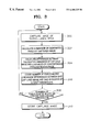
- FIG. 3 is a flow chart illustrating a surveillance method according to the present invention.
- FIG. 4 is a detailed flow chart of the surveillance method illustrated in FIG. 3 .
- FIG. 1 is a block diagram of an earlier surveillance system.
- the surveillance system of FIG. 1 is composed of a camera 100 installed in a surveillance area, a CCTV 110 installed in an observation room and connected to the camera 100 , and a video tape recorder connected to the CCTV for storing video footage displayed on the CCTV 110 .
- the video tape recorder 112 is for recording video footage when the guard is absent.
- FIG. 2A is a block diagram of a surveillance system using a personal computer according to the present invention.
- the surveillance system shown in FIG. 2A includes a camera unit 200 installed in a surveillance area, and a surveillance unit 210 comprising an image capturing unit 212 , a temporary previous image storing unit 214 , a control unit 216 , and a permanent image storing unit 218 .
- the temporary previous image storing unit 214 is a temporary storage unit used only to compare the luminance of pixels within it with the luminance of corresponding pixels of a subsequently captured image. Images in storage unit 214 are overwritten and thus lost each time a new image is captured.
- permanent image storing unit 218 is a form of permanent storage for selected images and can be part of a hard disk in a computer system.
- the camera unit 200 includes a camcorder, or a small camera for a computer employing charge coupled devices, and supplies images of the surveillance area to the surveillance unit 210 .
- the surveillance unit 210 may be, for example, a personal computer comprising a capture board for capturing an image, a hard disk storing selected images stored in permanent storage 218 for later review and scrutiny, and a processor for controlling the whole computer system.
- the surveillance unit 210 is installed in a surveillance room.
- the image capturing unit 212 periodically gets an image from the camera unit 200 at a time interval decided by the control unit 216 .
- a captured image by image capturing unit 212 is relayed to control unit 216 for calculation of luminance values with a previously stored image found in temporary memory 214 .
- the control unit 216 calculates luminance values from R (red), G (green) and B (blue) values of pixels of the image captured by the image capturing unit 212 , and calculates differences between the found luminance values and those of the corresponding pixels of the previous image stored in the temporary previous image storing unit 214 .
- the luminance calculation of pixels may be performed only on pixels selected by a user at the discretion of the user or may include calculation of luminance of every pixel.
- the captured image is then also stored in permanent memory 218 . Regardless of whether the captured image is permanently stored or not, each captured image is temporarily stored in temporary storage 214 directly from image capturing unit 212 . Upon storing an image in temporary storage 214 , any previous image stored in temporary storage 214 is overwritten.
- FIG. 2B is a side view of a physically installed example of the surveillance system illustrated in FIG. 2A, and shows a configuration of the surveillance system in which a camera 222 is installed.
- Numeral 224 indicates the observable scope 224 of the camera 222 .
- a surveillance unit 220 compares a present image with a temporarily stored previous image, and stores the present image in both temporary memory 214 and in a permanent memory 218 when a moving object appears such as an intruder in the present image, and therefore the area within the observable scope 224 can be under surveillance.
- FIG. 3 is a flow chart illustrating a surveillance method using a personal computer according to the present invention, and shows the steps of processing an image captured by a camera. The operation of a surveillance system according to the present invention is described in detail with reference to the flow chart of FIG. 3 .
- Luminance values Y are calculated from the R, G and B values of selected pixels of the captured image by the following formula (step 302 ):
- Differences between the calculated luminance values and those of the corresponding selected pixels of the previous image are calculated (step 304 ). Pixels each having a calculated luminance difference larger than a first predetermined value k are counted (step 306 ). When the number of counted pixels in step 306 is less than or equal to a second predetermined number N, the current image captured is not permanently saved and the duration in time between capturing images is set to t 1 (step 308 and step 402 ). When the number of pixels in step 306 is greater than the second predetermined number N, the current image captured is stored and the duration in time between capturing images is set to t 2 which is less than t 1 (Step 310 and step 404 ).
- FIG. 4 is a detailed flow chart of the surveillance method illustrated in FIG. 3, and in FIG. 4, the steps 300 through 310 are the same as those of FIG. 3 but FIG. 4 is different from FIG. 3 in that the time At between capturing images is variable in FIG. 4 as mentioned previously.
- the time difference between capturing images is ⁇ t (step 400 ), and luminance values are found and differences between the found luminance values of user selected pixels of the captured image and those of corresponding user selected pixels of the previous image that is temporarily stored are calculated.
- Pixels having a calculated difference in luminance larger than a first predetermined value k are counted (steps 300 through 306 ) and the time interval between captured images ⁇ t is set to t 1 (step 402 ) when the counted number n is smaller than or equal to the second predetermined value N (step 308 ).
- the image only stored in temporary memory 214 overwriting the a previous image previously stored in the temporary memory.
- the time interval between captured images ⁇ t is set to t 2 (step 404 ) after the captured image is stored both in a permanent memory 218 and in temporary memory 214 (step 310 ).
- t 2 is smaller than t 2 to allow for more images when captured images are in a state of change. Accordingly, images can be stored at shorter intervals when there are more variations in images.
- the surveillance operation is stopped (step 406 ).
- FIGS. 3 and 4 pertain to the scenario where a user selects which pixels in an image are used to determine luminance and eventually whether the captured image is stored, it is to be understood that the user can select every pixel in the image and thus FIGS. 3 and 4 work equally well when every pixel is used in this process instead of just user selected pixels.
Abstract
Description
Claims (3)
Applications Claiming Priority (2)
| Application Number | Priority Date | Filing Date | Title |
|---|---|---|---|
| KR98-5960 | 1998-02-25 | ||
| KR1019980005960A KR100457506B1 (en) | 1998-02-25 | 1998-02-25 | Monitoring system and method thereof using pc having screen acquisition board |
Publications (1)
| Publication Number | Publication Date |
|---|---|
| US6480225B1 true US6480225B1 (en) | 2002-11-12 |
Family
ID=19533720
Family Applications (1)
| Application Number | Title | Priority Date | Filing Date |
|---|---|---|---|
| US09/257,180 Expired - Lifetime US6480225B1 (en) | 1998-02-25 | 1999-02-25 | Surveillance system and method using personal computer |
Country Status (2)
| Country | Link |
|---|---|
| US (1) | US6480225B1 (en) |
| KR (1) | KR100457506B1 (en) |
Cited By (14)
| Publication number | Priority date | Publication date | Assignee | Title |
|---|---|---|---|---|
| US20010052933A1 (en) * | 2000-01-12 | 2001-12-20 | Nybo Larry Carl | System and method for image capture, storage and retrieval |
| US20020101530A1 (en) * | 2001-01-29 | 2002-08-01 | Philips Electronics North America Corporation | Camera system and method for operating same |
| US20040184529A1 (en) * | 2003-02-14 | 2004-09-23 | Canon Europa N.V. | Method and device for analyzing video sequences in a communication network |
| US6803945B1 (en) * | 1999-09-21 | 2004-10-12 | Intel Corporation | Motion detecting web camera system |
| US20040212678A1 (en) * | 2003-04-25 | 2004-10-28 | Cooper Peter David | Low power motion detection system |
| US20040246336A1 (en) * | 2003-06-04 | 2004-12-09 | Model Software Corporation | Video surveillance system |
| US20060203101A1 (en) * | 2005-03-14 | 2006-09-14 | Silsby Christopher D | Motion detecting camera system |
| US20060255241A1 (en) * | 2005-05-16 | 2006-11-16 | Seiko Epson Corporation | Integrated circuit device, microcomputer, and monitoring camera system |
| US20070098379A1 (en) * | 2005-09-20 | 2007-05-03 | Kang-Huai Wang | In vivo autonomous camera with on-board data storage or digital wireless transmission in regulatory approved band |
| US20070230930A1 (en) * | 2006-02-03 | 2007-10-04 | Benq Corporation | Methods and systems for automatic image acquisition |
| US20070258807A1 (en) * | 2006-05-04 | 2007-11-08 | Siemens Power Generation, Inc. | Infrared-based method and apparatus for online detection of cracks in steam turbine components |
| US7577199B1 (en) | 2003-06-19 | 2009-08-18 | Nvidia Corporation | Apparatus and method for performing surveillance using motion vectors |
| US20090312956A1 (en) * | 1999-12-22 | 2009-12-17 | Zombo Paul J | Method and apparatus for measuring on-line failure of turbine thermal barrier coatings |
| US20100220180A1 (en) * | 2006-09-19 | 2010-09-02 | Capso Vision, Inc. | Capture Control for in vivo Camera |
Citations (10)
| Publication number | Priority date | Publication date | Assignee | Title |
|---|---|---|---|---|
| US3825676A (en) | 1972-07-07 | 1974-07-23 | Sanders Associates Inc | Surveillance system |
| US5134472A (en) | 1989-02-08 | 1992-07-28 | Kabushiki Kaisha Toshiba | Moving object detection apparatus and method |
| US5289275A (en) * | 1991-07-12 | 1994-02-22 | Hochiki Kabushiki Kaisha | Surveillance monitor system using image processing for monitoring fires and thefts |
| US5588067A (en) | 1993-02-19 | 1996-12-24 | Peterson; Fred M. | Motion detection and image acquisition apparatus and method of detecting the motion of and acquiring an image of an object |
| US5666157A (en) | 1995-01-03 | 1997-09-09 | Arc Incorporated | Abnormality detection and surveillance system |
| US5703618A (en) * | 1995-11-22 | 1997-12-30 | Cirrus Logic, Inc. | Method and apparatus for upscaling video images when pixel data used for upscaling a source video image are unavailable |
| US5751346A (en) * | 1995-02-10 | 1998-05-12 | Dozier Financial Corporation | Image retention and information security system |
| US5880775A (en) * | 1993-08-16 | 1999-03-09 | Videofaxx, Inc. | Method and apparatus for detecting changes in a video display |
| US6067169A (en) * | 1994-03-15 | 2000-05-23 | Canon Kabushiki Kaisha | Color image process system, color image apparatus, color image processing method |
| US6185314B1 (en) * | 1997-06-19 | 2001-02-06 | Ncr Corporation | System and method for matching image information to object model information |
-
1998
- 1998-02-25 KR KR1019980005960A patent/KR100457506B1/en not_active IP Right Cessation
-
1999
- 1999-02-25 US US09/257,180 patent/US6480225B1/en not_active Expired - Lifetime
Patent Citations (10)
| Publication number | Priority date | Publication date | Assignee | Title |
|---|---|---|---|---|
| US3825676A (en) | 1972-07-07 | 1974-07-23 | Sanders Associates Inc | Surveillance system |
| US5134472A (en) | 1989-02-08 | 1992-07-28 | Kabushiki Kaisha Toshiba | Moving object detection apparatus and method |
| US5289275A (en) * | 1991-07-12 | 1994-02-22 | Hochiki Kabushiki Kaisha | Surveillance monitor system using image processing for monitoring fires and thefts |
| US5588067A (en) | 1993-02-19 | 1996-12-24 | Peterson; Fred M. | Motion detection and image acquisition apparatus and method of detecting the motion of and acquiring an image of an object |
| US5880775A (en) * | 1993-08-16 | 1999-03-09 | Videofaxx, Inc. | Method and apparatus for detecting changes in a video display |
| US6067169A (en) * | 1994-03-15 | 2000-05-23 | Canon Kabushiki Kaisha | Color image process system, color image apparatus, color image processing method |
| US5666157A (en) | 1995-01-03 | 1997-09-09 | Arc Incorporated | Abnormality detection and surveillance system |
| US5751346A (en) * | 1995-02-10 | 1998-05-12 | Dozier Financial Corporation | Image retention and information security system |
| US5703618A (en) * | 1995-11-22 | 1997-12-30 | Cirrus Logic, Inc. | Method and apparatus for upscaling video images when pixel data used for upscaling a source video image are unavailable |
| US6185314B1 (en) * | 1997-06-19 | 2001-02-06 | Ncr Corporation | System and method for matching image information to object model information |
Non-Patent Citations (1)
| Title |
|---|
| Gonzalez, Rafael C., digital image processing, 1992, addison-wesley publishing company, 221-230. * |
Cited By (28)
| Publication number | Priority date | Publication date | Assignee | Title |
|---|---|---|---|---|
| US20050007454A1 (en) * | 1999-09-21 | 2005-01-13 | Needham Bradford H. | Motion detecting web camera system |
| US6803945B1 (en) * | 1999-09-21 | 2004-10-12 | Intel Corporation | Motion detecting web camera system |
| US7690840B2 (en) * | 1999-12-22 | 2010-04-06 | Siemens Energy, Inc. | Method and apparatus for measuring on-line failure of turbine thermal barrier coatings |
| US20090312956A1 (en) * | 1999-12-22 | 2009-12-17 | Zombo Paul J | Method and apparatus for measuring on-line failure of turbine thermal barrier coatings |
| US20010052933A1 (en) * | 2000-01-12 | 2001-12-20 | Nybo Larry Carl | System and method for image capture, storage and retrieval |
| US20020101530A1 (en) * | 2001-01-29 | 2002-08-01 | Philips Electronics North America Corporation | Camera system and method for operating same |
| US20040184529A1 (en) * | 2003-02-14 | 2004-09-23 | Canon Europa N.V. | Method and device for analyzing video sequences in a communication network |
| US7466865B2 (en) | 2003-02-14 | 2008-12-16 | Canon Europa, N.V. | Method and device for analyzing video sequences in a communication network |
| US20040212678A1 (en) * | 2003-04-25 | 2004-10-28 | Cooper Peter David | Low power motion detection system |
| US7859564B2 (en) | 2003-06-04 | 2010-12-28 | Model Software Corporation | Video surveillance system |
| US8605155B2 (en) | 2003-06-04 | 2013-12-10 | Model Software Corporation | Video surveillance system |
| US20040246336A1 (en) * | 2003-06-04 | 2004-12-09 | Model Software Corporation | Video surveillance system |
| US7577199B1 (en) | 2003-06-19 | 2009-08-18 | Nvidia Corporation | Apparatus and method for performing surveillance using motion vectors |
| US7643056B2 (en) * | 2005-03-14 | 2010-01-05 | Aptina Imaging Corporation | Motion detecting camera system |
| US20060203101A1 (en) * | 2005-03-14 | 2006-09-14 | Silsby Christopher D | Motion detecting camera system |
| US7482569B2 (en) * | 2005-05-16 | 2009-01-27 | Seiko Epson Corporation | Integrated circuit device, microcomputer, and monitoring camera system |
| US20060255241A1 (en) * | 2005-05-16 | 2006-11-16 | Seiko Epson Corporation | Integrated circuit device, microcomputer, and monitoring camera system |
| US20090322865A1 (en) * | 2005-09-20 | 2009-12-31 | Capso Vision, Inc. | Image capture control for in vivo autonomous camera |
| US7792344B2 (en) * | 2005-09-20 | 2010-09-07 | Capso Vision Inc. | Image capture control for in vivo autonomous camera |
| US20070098379A1 (en) * | 2005-09-20 | 2007-05-03 | Kang-Huai Wang | In vivo autonomous camera with on-board data storage or digital wireless transmission in regulatory approved band |
| US7983458B2 (en) * | 2005-09-20 | 2011-07-19 | Capso Vision, Inc. | In vivo autonomous camera with on-board data storage or digital wireless transmission in regulatory approved band |
| US8073223B2 (en) * | 2005-09-20 | 2011-12-06 | Capso Vision Inc. | In vivo autonomous camera with on-board data storage or digital wireless transmission in regulatory approved band |
| US20070230930A1 (en) * | 2006-02-03 | 2007-10-04 | Benq Corporation | Methods and systems for automatic image acquisition |
| US7432505B2 (en) | 2006-05-04 | 2008-10-07 | Siemens Power Generation, Inc. | Infrared-based method and apparatus for online detection of cracks in steam turbine components |
| US20070258807A1 (en) * | 2006-05-04 | 2007-11-08 | Siemens Power Generation, Inc. | Infrared-based method and apparatus for online detection of cracks in steam turbine components |
| US20100220180A1 (en) * | 2006-09-19 | 2010-09-02 | Capso Vision, Inc. | Capture Control for in vivo Camera |
| US7940973B2 (en) * | 2006-09-19 | 2011-05-10 | Capso Vision Inc. | Capture control for in vivo camera |
| US7974454B1 (en) * | 2010-05-10 | 2011-07-05 | Capso Vision Inc. | Capture control for in vivo camera |
Also Published As
| Publication number | Publication date |
|---|---|
| KR19990070854A (en) | 1999-09-15 |
| KR100457506B1 (en) | 2005-01-17 |
Similar Documents
| Publication | Publication Date | Title |
|---|---|---|
| US6480225B1 (en) | Surveillance system and method using personal computer | |
| JP3689946B2 (en) | Data processing apparatus and method | |
| US5731832A (en) | Apparatus and method for detecting motion in a video signal | |
| JP4803376B2 (en) | Camera tampering detection method | |
| KR100872878B1 (en) | Imaging System of Security Camera by Event Detection | |
| US5986695A (en) | Recording method and apparatus for conserving space on recording medium of security system | |
| JPH11252534A (en) | Camera system | |
| JPH04213973A (en) | Image shake corrector | |
| JPH10136252A (en) | Image pickup device | |
| KR970008283B1 (en) | Method and scene recording system for closed circuit television | |
| EP1465412A2 (en) | Network image pickup apparatus, network image pickup system, and network image pickup method | |
| JPH05328201A (en) | Correction device for camera shake of picture | |
| KR100278989B1 (en) | Closed Circuit Monitoring Apparatus and Method | |
| KR100391266B1 (en) | Method for background setup in object-based compression moving-image | |
| KR102587499B1 (en) | Image storage apparatus and method capable of extending storage period and making the situation easy to grasp | |
| KR100197586B1 (en) | Camcorder that can be used as a monitoring camera | |
| JP3823129B2 (en) | Image search system and image search method | |
| JPH08265736A (en) | Cctv monitoring system | |
| JP3642094B2 (en) | Imaging system and control method thereof | |
| KR0171822B1 (en) | Image signal superposition display method | |
| JPH1127654A (en) | Monitoring camera and monitoring system | |
| JPH08186792A (en) | Image fetching device | |
| KR19980073933A (en) | Motion Detection Method of Closed Circuit Television System | |
| JPH01251195A (en) | Monitor | |
| JPH06141323A (en) | Monitor camera system |
Legal Events
| Date | Code | Title | Description |
|---|---|---|---|
| AS | Assignment |
Owner name: SAMSUNG ELECTRONICS CO., LTD., KOREA, REPUBLIC OF Free format text: ASSIGNMENT OF ASSIGNORS INTEREST;ASSIGNOR:KIM, BONG-SEOK;REEL/FRAME:010200/0077 Effective date: 19990601 |
|
| STCF | Information on status: patent grant |
Free format text: PATENTED CASE |
|
| FEPP | Fee payment procedure |
Free format text: PAYOR NUMBER ASSIGNED (ORIGINAL EVENT CODE: ASPN); ENTITY STATUS OF PATENT OWNER: LARGE ENTITY |
|
| FPAY | Fee payment |
Year of fee payment: 4 |
|
| FEPP | Fee payment procedure |
Free format text: PAYER NUMBER DE-ASSIGNED (ORIGINAL EVENT CODE: RMPN); ENTITY STATUS OF PATENT OWNER: LARGE ENTITY Free format text: PAYOR NUMBER ASSIGNED (ORIGINAL EVENT CODE: ASPN); ENTITY STATUS OF PATENT OWNER: LARGE ENTITY |
|
| AS | Assignment |
Owner name: TRANSPACIFIC AVARTAR, LLC, DELAWARE Free format text: ASSIGNMENT OF ASSIGNORS INTEREST;ASSIGNOR:SAMSUNG ELECTRONICS CO., LTD.;REEL/FRAME:022034/0236 Effective date: 20081030 |
|
| FPAY | Fee payment |
Year of fee payment: 8 |
|
| FEPP | Fee payment procedure |
Free format text: PAYER NUMBER DE-ASSIGNED (ORIGINAL EVENT CODE: RMPN); ENTITY STATUS OF PATENT OWNER: LARGE ENTITY Free format text: PAYOR NUMBER ASSIGNED (ORIGINAL EVENT CODE: ASPN); ENTITY STATUS OF PATENT OWNER: LARGE ENTITY |
|
| FPAY | Fee payment |
Year of fee payment: 12 |
|
| AS | Assignment |
Owner name: HANGER SOLUTIONS, LLC, GEORGIA Free format text: ASSIGNMENT OF ASSIGNORS INTEREST;ASSIGNOR:INTELLECTUAL VENTURES ASSETS 158 LLC;REEL/FRAME:051486/0425 Effective date: 20191206 |
|
| AS | Assignment |
Owner name: INTELLECTUAL VENTURES ASSETS 158 LLC, DELAWARE Free format text: ASSIGNMENT OF ASSIGNORS INTEREST;ASSIGNOR:TRANSPACIFIC AVARTAR, LLC;REEL/FRAME:051856/0331 Effective date: 20191126 |