US6487606B1 - System and method for delivering messages through a totem communications system - Google Patents
System and method for delivering messages through a totem communications system Download PDFInfo
- Publication number
- US6487606B1 US6487606B1 US09/195,067 US19506798A US6487606B1 US 6487606 B1 US6487606 B1 US 6487606B1 US 19506798 A US19506798 A US 19506798A US 6487606 B1 US6487606 B1 US 6487606B1
- Authority
- US
- United States
- Prior art keywords
- processor
- message
- cpu
- buffer memory
- network
- Prior art date
- Legal status (The legal status is an assumption and is not a legal conclusion. Google has not performed a legal analysis and makes no representation as to the accuracy of the status listed.)
- Expired - Fee Related
Links
Images


Classifications
-
- H—ELECTRICITY
- H04—ELECTRIC COMMUNICATION TECHNIQUE
- H04L—TRANSMISSION OF DIGITAL INFORMATION, e.g. TELEGRAPHIC COMMUNICATION
- H04L49/00—Packet switching elements
- H04L49/90—Buffering arrangements
- H04L49/9057—Arrangements for supporting packet reassembly or resequencing
-
- H—ELECTRICITY
- H04—ELECTRIC COMMUNICATION TECHNIQUE
- H04L—TRANSMISSION OF DIGITAL INFORMATION, e.g. TELEGRAPHIC COMMUNICATION
- H04L49/00—Packet switching elements
- H04L49/90—Buffering arrangements
-
- H—ELECTRICITY
- H04—ELECTRIC COMMUNICATION TECHNIQUE
- H04L—TRANSMISSION OF DIGITAL INFORMATION, e.g. TELEGRAPHIC COMMUNICATION
- H04L9/00—Cryptographic mechanisms or cryptographic arrangements for secret or secure communications; Network security protocols
- H04L9/40—Network security protocols
Definitions
- the invention relates generally to communication systems and, more particularly, to an improved method and system for configuring Totem communication systems.
- a number of systems have been developed for providing network communications among groups.
- One such system is a Totem ring system, in which a plurality of host processors are electrically connected to a bus, each of which host processors includes a Central Processing Unit (CPU) adapted for executing processes such as application programs, including call processing, database operations, or any process requiring fault tolerance.
- CPU Central Processing Unit
- a Totem ring provides for the delivery of multicast messages and invokes operations in the same total order throughout a distributed system, thereby resulting in consistency of replicated data and simplified programming of applications.
- Totem systems are well known to those skilled in the art and are, for example, described in greater detail in an article entitled “Totem: A Fault Tolerant Multicast Group Communication System” by L. E. Moser et al., published in the April 1996, Vol. 39, No. 4 Edition of Communications of the ACM.
- Totem systems manage a number of different aspects of a communications system. For example, message delivery is controlled using a token similar to that used in a token ring to identify which host processor may transmit onto the ring. Periodically, such as every few milliseconds, the token is sent around the ring to each host processor in sequence. As the token is received by each host processor, the host processor determines whether it has a message or data to transmit over the ring. If a host processor does not have a message or data to transmit over the ring, then it regenerates the token and sends it to the next host processor. Each such query, response, and token regeneration, however, requires the CPU of a host processor to stop executing a process, such as an application program, while it responds to, and regenerates, the token. Typically, a processor has nothing to communicate, thereby rendering the token unnecessary the vast majority of the time. Furthermore, when such a cycle occurs every few milliseconds, the processing overhead for a CPU becomes, not only unnecessary, but also significant.
- Totem systems also provide for virtual synchrony upon which a process, such as an application program, is loaded onto two host processors, one of which is designated as an active processor and the other of which is designated as a standby processor. If the active processor fails, then execution of the process is transferred to the standby processor. Determination of a failed processor, though, requires that, periodically, certain membership queries be made, via token retransmits, of the processors that are “members” of the Totem system. Such queries, as well as system configuration settings and other administrative functions performed by the Totem system, impose processing overhead on the CPUs of each of the host processors, in addition to the overhead imposed by the regeneration and forwarding of the aforementioned token, and further decrease the operating efficiency of the processors. Not only is the operating efficiency of the processors decreased, but the detection time of a processor failure is also degraded because the processors cannot quickly retransmit tokens since they are engaged predominantly in processing applications.
- a Totem system having a plurality of host processors is improved by providing each host processor with a co-processor and buffer memory which operate as an interface between a CPU of each host processor and the network of the Totem system.
- the co-processors relieve the processing overhead on the CPUs, thereby enabling each CPU and host processor to operate more efficiently.
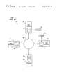
- FIG. 1 is a schematic diagram showing a Totem ring embodying features of the prior art
- FIG. 2 is a schematic diagram showing a Totem ring embodying features of the present invention.
- FIGS. 3-4 are a flow charts illustrating control logic for implementing the Totem ring shown in FIG. 2 .
- the reference numeral 10 generally designates a Totem system embodying features of the prior art.
- the system 10 is generally operable over a broadcast network and includes four host processors 12 , 14 , 16 , and 18 , each of which has a central processing unit (“CPU”) 22 , 24 , 26 , and 28 , respectively, electrically connected to a network 30 such as a 10-Mbit/s or 100-Mbit/s Ethernet. While four processors are shown, the number of processors may be more or less.
- CPU central processing unit
- the processors 12 , 14 , 16 , and 18 may comprise any conventional computer generally capable of receiving, storing, processing, and outputting data, such as, for example, microcomputers, such as IBM PCs, IBM PC clones, Sun Microsystems IPCs running SunOS 4.1, or Sun SPARCstation 20s running Solaris 2.4. While not shown, the processors 12 , 14 , 16 , and 18 include components, such as input and output devices, volatile and non-volatile memory, and the like, but, because such computer components are well known in the art, they are not shown or described further herein. Each of the CPUs 22 , 24 , 26 , and 28 is adaptable for executing processes such as application programs, including call processing, database operations, and the like.
- the host processors 12 and 14 will be loaded with substantially identical processes 32 and 34 , respectively, such as application programs.
- one processor such as the processor 12
- the other processor i.e., the processor 14
- the active and standby processors 12 and 14 are configured so that the active processor 12 executes the process 32 until a fault occurs in the system 10 which prevents the active processor 12 from being able to execute the process, at which point execution of the process is transferred to the standby processor, which then becomes the active processor, and thereby provides fault tolerance in the system.
- a token (not shown) is sent to each processor 12 , 14 , 16 , and 18 in a predetermined sequential order.
- execution of a process such as an application program, by a respective CPU 22 , 24 , 26 , and 28 is interrupted, and a determination is made by the respective CPU whether the processor has any message to communicate to the network 30 or to another processor connected to the network 30 . If a processor, such as the processor 12 , has a message to communicate, then its respective CPU 22 delivers the message to the network 30 with the address of the processor, such as the processor 14 , to which the message is to be delivered.
- a processor such as the processor 14
- its CPU regenerates the token and sends it to the next processor.
- the CPU 22 or 26 of the processor 12 or 16 respectively, then resumes execution of the application program which it was performing prior to the interruption by the token. It can be appreciated that the interruption of a CPU by a token when it does not have a message to deliver, and the regeneration of the token, imposes unnecessary overhead on the CPU, which slows it down and renders it less efficient that it would otherwise be.
- the Totem system 10 In addition to the overhead imposed by sending the token sequentially to each processor 12 , 14 , 16 , and 18 , and regenerating the token by each processor, the Totem system 10 also imposes many other overhead burdens onto each processor to provide the system 10 with fault tolerance. For example, as discussed above, the Totem system 10 provides for virtual synchrony whereby a standby processor, such as the processor 14 , continues execution of a process, such as the process 34 , when an active processor, such as the processor 12 , fails. The Totem system 10 also provides for many membership and system configuration services involving, for example, the delivery of “join” and “commit” messages.
- Totem A Fault Tolerant Multicast Group Communication System
- L. E. Moser et al. published in the April 1996, Vol. 39, No. 4 Edition of Communications of the ACM, pp. 54-63, which article is incorporated in its entirety by reference herein. It is therefore considered unnecessary to discuss the operation and many services of a Totem system in greater detail herein. It can be appreciated, however, that such services necessitate interruptions of each CPU every few milliseconds and, as a result, add to a processor significant overhead which, in the majority of cases, is unnecessary.
- FIG. 2 an embodiment of the present invention is shown which substantially reduces the processing overhead imposed by the Totem system 10 on each processor 12 , 14 , 16 , and 18 .
- the embodiment shown in FIG. 2 comprises a modification of the Totem system 10 in which the CPU 22 , 24 , 26 , and 28 of each of the processors 12 , 14 , 16 , and 18 , respectively, are electrically connected in data communication to a buffer memory 52 , 54 , 56 , and 58 , respectively, such as conventional random access memory (RAM).
- RAM random access memory
- Each buffer memory 52 , 54 , 56 , and 58 is electrically connected in data communication to a co-processor 62 , 64 , 66 , and 68 , respectively, which is electrically connected in data communication to the network 30 for providing an interface between the respective CPU 22 , 24 , 26 , and 28 and the network 30 .
- the co-processors 62 , 64 , 66 , and 68 may comprise any suitable processor, such as, for example, a PowerPC 604, an Intel Pentium, a RISC processor, or the like, and are provided with control logic, described below, for its operation.
- FIG. 3 is a flowchart of control logic which may be implemented by the co-processors 62 , 64 , 66 , and 68 to operate as a front end interface between the network 30 and the CPUs 22 , 24 , 26 , and 28 in accordance with the present invention.
- the control logic in each co-processor 62 , 64 , 66 , and 68 is substantially identical and, for the sake of conciseness, will be exemplified by showing how a message, including data or an administrative or membership query message such as a join or commit message, is delivered from the host processor 12 to the host processor 16 .
- a CPU 22 , 24 , 26 , and 28 Prior to or at any point during execution of the control logic by a co-processor 62 , 64 , 66 , and 68 , if a CPU 22 , 24 , 26 , and 28 has a message to deliver, then it delivers such message to the buffer memory 52 , without waiting for a token to send the message, thereby freeing up the CPU 22 to do other tasks.
- step 300 execution begins and, in step 302 , the co-processor 62 of the host processor 12 determines whether it has received the token. If, in step 302 , the co-processor 62 determines that it has not received the token, then execution returns to step 302 ; otherwise, execution proceeds to step 304 .
- step 304 the co-processor 62 determines whether there is a message in the buffer memory 52 (stored there by the CPU 22 ) that is awaiting delivery. If, in step 304 , it is determined that there is not a message awaiting delivery, then execution proceeds to step 306 . In step 306 , the token is regenerated and sent to the next processor and execution returns to step 302 .
- step 304 If, in step 304 , it is determined that a message is awaiting delivery, then execution proceeds to step 308 in which the co-processor 62 retrieves the message stored in the buffer memory 52 .
- step 310 the co-processor 62 sends the retrieved message through the network to the co-processor 66 of the selected recipient host processor 16 . Execution then proceeds to step 306 , described above.
- FIG. 4 shows the control logic implemented by the co-processor 66 upon receipt in step 400 of the message delivered in the foregoing step 310 (FIG. 3) to the selected recipient host processor.
- the co-processor 66 determines whether the received message is a message, such as a membership query message, to which the co-processor 66 can respond. If the co-processor 66 determines that it can respond to the message, then, in step 404 , it prepares a reply accordingly and, in step 406 , it delivers the reply to the network 30 .
- the co-processor 66 determines whether any of the information content of the message or of the reply to the message should be forwarded to the CPU 26 .
- step 408 the co-processor 66 determines that no information content of the message or of the reply to the message should be forwarded to the CPU 26 . If, in step 408 , the co-processor 66 determines that at least some of the information content of the message or of the reply to the message should be forwarded to the CPU 26 , then execution proceeds to step 412 in which such information content is stored in the buffer memory 56 . Execution then proceeds to step 414 in which the co-processor 66 generates an interrupt signal to the CPU 26 to indicate that a message or information content reside in the buffer memory 56 for the CPU to retrieve.
- step 414 Upon receipt of the interrupt signal, the CPU 26 retrieves the message from the buffer memory 56 , thereby completing the delivery of the message. Upon completion of step 414 , execution terminates at step 410 . If, in step 402 , the co-processor 66 does not determine that it can respond to the message, then, in step 416 , the co-processor 66 stores the information in its respective buffer memory 56 and execution proceeds to step 414 . earliest
- Any message may be delivered from any host processor 12 , 14 , 16 , or 18 to any other host processor a manner similar to that described above with respect to FIGS. 3-4.
- the processing overhead previously carried by the CPUs 12 , 14 , 16 , and 18 may be largely carried by the respective co-processors 62 , 64 , 66 , and 68 , and the CPUs may be utilized more efficiently for performing other non-overhead tasks they were designed for.
- the co-processors 62 , 64 , 66 , and 68 are dedicated to handling the administrative tasks of the Totem system, the token can be re-transmitted more quickly through the system, wait time for a token can be reduced, and failure of a token retransmit, and hence of a host processor, may be detected and remedied more quickly than in systems which do not utilize co-processors, thereby further enhancing the fault tolerance of the system. Because the co-processors are typically less expensive than the CPUs, they also provide a cost benefit when compared to the prior art.
- the present invention can take many forms and embodiments. Accordingly, several variations may be made in the foregoing without departing from the spirit or the scope of the invention.
- the present invention may be used with Totem systems comprising multiple ring protocols as well as single ring protocols.
- it may also be used with token bus systems.
- a communications chip (not shown), such as an Ethernet chip, may be provided for the co-processors in a manner well known to those skilled in the art for facilitating communication of data between the network 30 and each co-processor 52 , 54 , 56 , and 58 .
- the steps 402 - 408 and 410 depicted in FIG. 4 may be omitted.
- a host processor may be a standby host processor for more than one active host processor.
Abstract
Description
Claims (25)
Priority Applications (3)
| Application Number | Priority Date | Filing Date | Title |
|---|---|---|---|
| US09/195,067 US6487606B1 (en) | 1998-11-18 | 1998-11-18 | System and method for delivering messages through a totem communications system |
| CA002290034A CA2290034A1 (en) | 1998-11-18 | 1999-11-17 | Improved totem communications system and method |
| EP99309171A EP1003314A3 (en) | 1998-11-18 | 1999-11-18 | Improved totem communications system and method |
Applications Claiming Priority (1)
| Application Number | Priority Date | Filing Date | Title |
|---|---|---|---|
| US09/195,067 US6487606B1 (en) | 1998-11-18 | 1998-11-18 | System and method for delivering messages through a totem communications system |
Publications (1)
| Publication Number | Publication Date |
|---|---|
| US6487606B1 true US6487606B1 (en) | 2002-11-26 |
Family
ID=22719922
Family Applications (1)
| Application Number | Title | Priority Date | Filing Date |
|---|---|---|---|
| US09/195,067 Expired - Fee Related US6487606B1 (en) | 1998-11-18 | 1998-11-18 | System and method for delivering messages through a totem communications system |
Country Status (3)
| Country | Link |
|---|---|
| US (1) | US6487606B1 (en) |
| EP (1) | EP1003314A3 (en) |
| CA (1) | CA2290034A1 (en) |
Cited By (8)
| Publication number | Priority date | Publication date | Assignee | Title |
|---|---|---|---|---|
| US6965922B1 (en) * | 2000-04-18 | 2005-11-15 | International Business Machines Corporation | Computer system and method with internal use of networking switching |
| US20060042079A1 (en) * | 2004-08-26 | 2006-03-02 | King L H Jr | Dip molded wire connector |
| US20060245375A1 (en) * | 2005-04-27 | 2006-11-02 | Broadcom Corporation | Method for communication between processors |
| US20090055909A1 (en) * | 2007-08-20 | 2009-02-26 | National Taiwan University Of Science And Technology | Data transmitting method with multiple token mechanism in wireless token ring protocol |
| US7609703B2 (en) | 2006-09-15 | 2009-10-27 | Hewlett-Packard Development Company, L.P. | Group communication system and method |
| US7972166B2 (en) | 2007-06-29 | 2011-07-05 | The Patent Store, Llc | Waterproof push-in wire connectors |
| US20120011150A1 (en) * | 2009-07-14 | 2012-01-12 | Ashwin Swaminathan | Methods and Apparatus for Efficiently Processing Multiple Keyword Queries on a Distributed Network |
| US20210206895A1 (en) * | 2018-09-28 | 2021-07-08 | Borealis Ag | Process for producing a heterophasic propylene copolymer having a high xylene cold soluble fraction (xcs) |
Families Citing this family (1)
| Publication number | Priority date | Publication date | Assignee | Title |
|---|---|---|---|---|
| CN105323160B (en) * | 2014-07-23 | 2021-01-26 | 中兴通讯股份有限公司 | Message receiving and sending method and device, channel unit and communication equipment |
Citations (16)
| Publication number | Priority date | Publication date | Assignee | Title |
|---|---|---|---|---|
| US5307459A (en) * | 1992-07-28 | 1994-04-26 | 3Com Corporation | Network adapter with host indication optimization |
| US5414831A (en) * | 1993-12-30 | 1995-05-09 | Lsi Logic Corporation | Apparatus and method for accessing a plurality of computer devices having a common address |
| US5434976A (en) * | 1992-09-28 | 1995-07-18 | Standard Microsystems Corporation | Communications controller utilizing an external buffer memory with plural channels between a host and network interface operating independently for transferring packets between protocol layers |
| US5469545A (en) * | 1991-10-03 | 1995-11-21 | Compaq Computer Corp. | Expandable communication system with data flow control |
| US5664116A (en) * | 1995-07-07 | 1997-09-02 | Sun Microsystems, Inc. | Buffering of data for transmission in a computer communication system interface |
| US5717855A (en) * | 1994-02-28 | 1998-02-10 | International Business Machines Corporation | Segmented communications adapter with packet transfer interface |
| US5745693A (en) * | 1992-07-01 | 1998-04-28 | Mci Corporation | System for gathering and reporting real time data from an IDNX communications network |
| US5764896A (en) * | 1996-06-28 | 1998-06-09 | Compaq Computer Corporation | Method and system for reducing transfer latency when transferring data from a network to a computer system |
| US5790804A (en) * | 1994-04-12 | 1998-08-04 | Mitsubishi Electric Information Technology Center America, Inc. | Computer network interface and network protocol with direct deposit messaging |
| US5832216A (en) * | 1994-11-04 | 1998-11-03 | Texas Instruments Incorporated | Network adapter having single ported memory which is accessible by network and peripheral bus on a time division multiplexed (TDM) basis |
| US5841444A (en) * | 1996-03-21 | 1998-11-24 | Samsung Electronics Co., Ltd. | Multiprocessor graphics system |
| US5948089A (en) * | 1997-09-05 | 1999-09-07 | Sonics, Inc. | Fully-pipelined fixed-latency communications system with a real time dynamic bandwidth allocation |
| US5978838A (en) * | 1996-08-19 | 1999-11-02 | Samsung Electronics Co., Ltd. | Coordination and synchronization of an asymmetric, single-chip, dual multiprocessor |
| US6101321A (en) * | 1992-04-10 | 2000-08-08 | Eastman Kodak Company | Method and apparatus for broadcasting data in a ring connected multiprocessor |
| US6115776A (en) * | 1996-12-05 | 2000-09-05 | 3Com Corporation | Network and adaptor with time-based and packet number based interrupt combinations |
| US6128311A (en) * | 1998-02-26 | 2000-10-03 | 3Com Corporation | Method and system for interfacing parallelly interfaced devices through a serial bus |
Family Cites Families (4)
| Publication number | Priority date | Publication date | Assignee | Title |
|---|---|---|---|---|
| JPS57164636A (en) * | 1981-04-03 | 1982-10-09 | Hitachi Ltd | Control method for transmission system |
| US5237659A (en) * | 1989-07-27 | 1993-08-17 | Bull S.A. | Gateway device for connecting a computer bus to a ring network |
| AUPN573795A0 (en) * | 1995-10-02 | 1995-10-26 | Telefonaktiebolaget Lm Ericsson (Publ) | Transmitting data between multiple computer processors |
| US5742607A (en) * | 1995-12-20 | 1998-04-21 | Intel Corporation | Method and apparatus for controlling two way communication via disparate physical media |
-
1998
- 1998-11-18 US US09/195,067 patent/US6487606B1/en not_active Expired - Fee Related
-
1999
- 1999-11-17 CA CA002290034A patent/CA2290034A1/en not_active Abandoned
- 1999-11-18 EP EP99309171A patent/EP1003314A3/en not_active Withdrawn
Patent Citations (16)
| Publication number | Priority date | Publication date | Assignee | Title |
|---|---|---|---|---|
| US5469545A (en) * | 1991-10-03 | 1995-11-21 | Compaq Computer Corp. | Expandable communication system with data flow control |
| US6101321A (en) * | 1992-04-10 | 2000-08-08 | Eastman Kodak Company | Method and apparatus for broadcasting data in a ring connected multiprocessor |
| US5745693A (en) * | 1992-07-01 | 1998-04-28 | Mci Corporation | System for gathering and reporting real time data from an IDNX communications network |
| US5307459A (en) * | 1992-07-28 | 1994-04-26 | 3Com Corporation | Network adapter with host indication optimization |
| US5434976A (en) * | 1992-09-28 | 1995-07-18 | Standard Microsystems Corporation | Communications controller utilizing an external buffer memory with plural channels between a host and network interface operating independently for transferring packets between protocol layers |
| US5414831A (en) * | 1993-12-30 | 1995-05-09 | Lsi Logic Corporation | Apparatus and method for accessing a plurality of computer devices having a common address |
| US5717855A (en) * | 1994-02-28 | 1998-02-10 | International Business Machines Corporation | Segmented communications adapter with packet transfer interface |
| US5790804A (en) * | 1994-04-12 | 1998-08-04 | Mitsubishi Electric Information Technology Center America, Inc. | Computer network interface and network protocol with direct deposit messaging |
| US5832216A (en) * | 1994-11-04 | 1998-11-03 | Texas Instruments Incorporated | Network adapter having single ported memory which is accessible by network and peripheral bus on a time division multiplexed (TDM) basis |
| US5664116A (en) * | 1995-07-07 | 1997-09-02 | Sun Microsystems, Inc. | Buffering of data for transmission in a computer communication system interface |
| US5841444A (en) * | 1996-03-21 | 1998-11-24 | Samsung Electronics Co., Ltd. | Multiprocessor graphics system |
| US5764896A (en) * | 1996-06-28 | 1998-06-09 | Compaq Computer Corporation | Method and system for reducing transfer latency when transferring data from a network to a computer system |
| US5978838A (en) * | 1996-08-19 | 1999-11-02 | Samsung Electronics Co., Ltd. | Coordination and synchronization of an asymmetric, single-chip, dual multiprocessor |
| US6115776A (en) * | 1996-12-05 | 2000-09-05 | 3Com Corporation | Network and adaptor with time-based and packet number based interrupt combinations |
| US5948089A (en) * | 1997-09-05 | 1999-09-07 | Sonics, Inc. | Fully-pipelined fixed-latency communications system with a real time dynamic bandwidth allocation |
| US6128311A (en) * | 1998-02-26 | 2000-10-03 | 3Com Corporation | Method and system for interfacing parallelly interfaced devices through a serial bus |
Non-Patent Citations (1)
| Title |
|---|
| Moser, et al. "Totem: A Fault-Tolerant Multicast Group Communication System," Communications of the ACM, vol. 39, No. 4, (Apr. 1996) pp. 54-63. |
Cited By (12)
| Publication number | Priority date | Publication date | Assignee | Title |
|---|---|---|---|---|
| US6965922B1 (en) * | 2000-04-18 | 2005-11-15 | International Business Machines Corporation | Computer system and method with internal use of networking switching |
| US20060042079A1 (en) * | 2004-08-26 | 2006-03-02 | King L H Jr | Dip molded wire connector |
| US20060245375A1 (en) * | 2005-04-27 | 2006-11-02 | Broadcom Corporation | Method for communication between processors |
| US8432809B2 (en) * | 2005-04-27 | 2013-04-30 | Broadcom Corporation | Method for communication between processors |
| US7609703B2 (en) | 2006-09-15 | 2009-10-27 | Hewlett-Packard Development Company, L.P. | Group communication system and method |
| US7972166B2 (en) | 2007-06-29 | 2011-07-05 | The Patent Store, Llc | Waterproof push-in wire connectors |
| US20090055909A1 (en) * | 2007-08-20 | 2009-02-26 | National Taiwan University Of Science And Technology | Data transmitting method with multiple token mechanism in wireless token ring protocol |
| US7975074B2 (en) * | 2007-08-20 | 2011-07-05 | National Taiwan University Of Science And Technology | Data transmitting method with multiple token mechanism in wireless token ring protocol |
| US20120011150A1 (en) * | 2009-07-14 | 2012-01-12 | Ashwin Swaminathan | Methods and Apparatus for Efficiently Processing Multiple Keyword Queries on a Distributed Network |
| US8996568B2 (en) * | 2009-07-14 | 2015-03-31 | Qualcomm Incorporated | Methods and apparatus for efficiently processing multiple keyword queries on a distributed network |
| US20210206895A1 (en) * | 2018-09-28 | 2021-07-08 | Borealis Ag | Process for producing a heterophasic propylene copolymer having a high xylene cold soluble fraction (xcs) |
| US11859030B2 (en) * | 2018-09-28 | 2024-01-02 | Borealis Ag | Process for producing a heterophasic propylene copolymer having a high xylene cold soluble fraction (XCS) |
Also Published As
| Publication number | Publication date |
|---|---|
| CA2290034A1 (en) | 2000-05-18 |
| EP1003314A3 (en) | 2003-01-08 |
| EP1003314A2 (en) | 2000-05-24 |
Similar Documents
| Publication | Publication Date | Title |
|---|---|---|
| Amir et al. | Membership algorithms for multicast communication groups | |
| US5361334A (en) | Data processing and communication | |
| EP0062463B1 (en) | Computer or processor control systems | |
| US7194652B2 (en) | High availability synchronization architecture | |
| US6877107B2 (en) | Method for ensuring operation during node failures and network partitions in a clustered message passing server | |
| US7516176B2 (en) | Distributed request and response queues for service processor | |
| US7076689B2 (en) | Use of unique XID range among multiple control processors | |
| US7284236B2 (en) | Mechanism to change firmware in a high availability single processor system | |
| EP0475080B1 (en) | Distributed messaging system and method | |
| US7840611B2 (en) | High availability for event forwarding | |
| US6360279B1 (en) | True parallel client server system and method | |
| US20050246570A1 (en) | Dynamic modification of fragmentation size cluster communication parameter in clustered computer system | |
| US20040083358A1 (en) | Reboot manager usable to change firmware in a high availability single processor system | |
| US7562154B2 (en) | System and method for filtering stale messages resulting from membership changes in a distributed computing environment | |
| EP1099164A1 (en) | Methods and apparatus for processing administrative requests of a distributed network application executing in a clustered computing environment | |
| US20010011296A1 (en) | Method and apparatus for providing multiple commands to a server | |
| US6487606B1 (en) | System and method for delivering messages through a totem communications system | |
| KR19990082753A (en) | Data processing apparatus, method and computer program product for carrying out workload management with respect to a group of servers in an asynchronous client/server computing system | |
| WO2000017755A2 (en) | Protocol for replicated servers | |
| JPH10124470A (en) | Mechanism for calling processing of multiplexed message with small overhead of low context switching | |
| US7496681B2 (en) | System and method for extending virtual synchrony to wide area networks | |
| US6704801B1 (en) | Atomic transmission of multiple messages in a virtual synchrony environment | |
| US20200401446A1 (en) | Intermediary system for data streams | |
| Ramani et al. | Reliable messaging using the CORBA Notification service | |
| US6178444B1 (en) | System and method that prevent messages transferred among networked data processing systems from becoming out of sequence |
Legal Events
| Date | Code | Title | Description |
|---|---|---|---|
| AS | Assignment |
Owner name: NORTHERN TELECOM LIMITED, CANADA Free format text: ASSIGNMENT OF ASSIGNORS INTEREST;ASSIGNORS:MINYARD, TRENTON C.;STOVALL, GREGORY T.;REEL/FRAME:009597/0922 Effective date: 19981023 |
|
| AS | Assignment |
Owner name: NORTEL NETWORKS CORPORATION, CANADA Free format text: CHANGE OF NAME;ASSIGNOR:NORTHERN TELECOM LIMITED;REEL/FRAME:010567/0001 Effective date: 19990429 |
|
| AS | Assignment |
Owner name: NORTEL NETWORKS LIMITED, CANADA Free format text: CHANGE OF NAME;ASSIGNOR:NORTEL NETWORKS CORPORATION;REEL/FRAME:011195/0706 Effective date: 20000830 Owner name: NORTEL NETWORKS LIMITED,CANADA Free format text: CHANGE OF NAME;ASSIGNOR:NORTEL NETWORKS CORPORATION;REEL/FRAME:011195/0706 Effective date: 20000830 |
|
| FPAY | Fee payment |
Year of fee payment: 4 |
|
| FEPP | Fee payment procedure |
Free format text: PAYOR NUMBER ASSIGNED (ORIGINAL EVENT CODE: ASPN); ENTITY STATUS OF PATENT OWNER: LARGE ENTITY |
|
| AS | Assignment |
Owner name: CITIBANK, N.A., AS ADMINISTRATIVE AGENT,NEW YORK Free format text: SECURITY AGREEMENT;ASSIGNOR:AVAYA INC.;REEL/FRAME:023892/0500 Effective date: 20100129 Owner name: CITIBANK, N.A., AS ADMINISTRATIVE AGENT, NEW YORK Free format text: SECURITY AGREEMENT;ASSIGNOR:AVAYA INC.;REEL/FRAME:023892/0500 Effective date: 20100129 |
|
| AS | Assignment |
Owner name: CITICORP USA, INC., AS ADMINISTRATIVE AGENT, NEW YORK Free format text: SECURITY AGREEMENT;ASSIGNOR:AVAYA INC.;REEL/FRAME:023905/0001 Effective date: 20100129 Owner name: CITICORP USA, INC., AS ADMINISTRATIVE AGENT,NEW YO Free format text: SECURITY AGREEMENT;ASSIGNOR:AVAYA INC.;REEL/FRAME:023905/0001 Effective date: 20100129 Owner name: CITICORP USA, INC., AS ADMINISTRATIVE AGENT, NEW Y Free format text: SECURITY AGREEMENT;ASSIGNOR:AVAYA INC.;REEL/FRAME:023905/0001 Effective date: 20100129 |
|
| AS | Assignment |
Owner name: AVAYA INC.,NEW JERSEY Free format text: ASSIGNMENT OF ASSIGNORS INTEREST;ASSIGNOR:NORTEL NETWORKS LIMITED;REEL/FRAME:023998/0878 Effective date: 20091218 Owner name: AVAYA INC., NEW JERSEY Free format text: ASSIGNMENT OF ASSIGNORS INTEREST;ASSIGNOR:NORTEL NETWORKS LIMITED;REEL/FRAME:023998/0878 Effective date: 20091218 |
|
| FPAY | Fee payment |
Year of fee payment: 8 |
|
| AS | Assignment |
Owner name: BANK OF NEW YORK MELLON TRUST, NA, AS NOTES COLLATERAL AGENT, THE, PENNSYLVANIA Free format text: SECURITY AGREEMENT;ASSIGNOR:AVAYA INC., A DELAWARE CORPORATION;REEL/FRAME:025863/0535 Effective date: 20110211 Owner name: BANK OF NEW YORK MELLON TRUST, NA, AS NOTES COLLAT Free format text: SECURITY AGREEMENT;ASSIGNOR:AVAYA INC., A DELAWARE CORPORATION;REEL/FRAME:025863/0535 Effective date: 20110211 |
|
| AS | Assignment |
Owner name: BANK OF NEW YORK MELLON TRUST COMPANY, N.A., THE, PENNSYLVANIA Free format text: SECURITY AGREEMENT;ASSIGNOR:AVAYA, INC.;REEL/FRAME:030083/0639 Effective date: 20130307 Owner name: BANK OF NEW YORK MELLON TRUST COMPANY, N.A., THE, Free format text: SECURITY AGREEMENT;ASSIGNOR:AVAYA, INC.;REEL/FRAME:030083/0639 Effective date: 20130307 |
|
| REMI | Maintenance fee reminder mailed | ||
| LAPS | Lapse for failure to pay maintenance fees | ||
| STCH | Information on status: patent discontinuation |
Free format text: PATENT EXPIRED DUE TO NONPAYMENT OF MAINTENANCE FEES UNDER 37 CFR 1.362 |
|
| FP | Lapsed due to failure to pay maintenance fee |
Effective date: 20141126 |
|
| AS | Assignment |
Owner name: AVAYA INC., CALIFORNIA Free format text: BANKRUPTCY COURT ORDER RELEASING ALL LIENS INCLUDING THE SECURITY INTEREST RECORDED AT REEL/FRAME 025863/0535;ASSIGNOR:THE BANK OF NEW YORK MELLON TRUST, NA;REEL/FRAME:044892/0001 Effective date: 20171128 Owner name: AVAYA INC., CALIFORNIA Free format text: BANKRUPTCY COURT ORDER RELEASING ALL LIENS INCLUDING THE SECURITY INTEREST RECORDED AT REEL/FRAME 023892/0500;ASSIGNOR:CITIBANK, N.A.;REEL/FRAME:044891/0564 Effective date: 20171128 Owner name: AVAYA INC., CALIFORNIA Free format text: BANKRUPTCY COURT ORDER RELEASING ALL LIENS INCLUDING THE SECURITY INTEREST RECORDED AT REEL/FRAME 030083/0639;ASSIGNOR:THE BANK OF NEW YORK MELLON TRUST COMPANY, N.A.;REEL/FRAME:045012/0666 Effective date: 20171128 |
|
| AS | Assignment |
Owner name: SIERRA HOLDINGS CORP., NEW JERSEY Free format text: RELEASE BY SECURED PARTY;ASSIGNOR:CITICORP USA, INC.;REEL/FRAME:045045/0564 Effective date: 20171215 Owner name: AVAYA, INC., CALIFORNIA Free format text: RELEASE BY SECURED PARTY;ASSIGNOR:CITICORP USA, INC.;REEL/FRAME:045045/0564 Effective date: 20171215 |