US6489948B1 - Computer mouse having multiple cursor positioning inputs and method of operation - Google Patents
Computer mouse having multiple cursor positioning inputs and method of operation Download PDFInfo
- Publication number
- US6489948B1 US6489948B1 US09/552,926 US55292600A US6489948B1 US 6489948 B1 US6489948 B1 US 6489948B1 US 55292600 A US55292600 A US 55292600A US 6489948 B1 US6489948 B1 US 6489948B1
- Authority
- US
- United States
- Prior art keywords
- input
- mouse
- cursor positioning
- computer
- dimensional
- Prior art date
- Legal status (The legal status is an assumption and is not a legal conclusion. Google has not performed a legal analysis and makes no representation as to the accuracy of the status listed.)
- Expired - Fee Related
Links
Images


Classifications
-
- G—PHYSICS
- G06—COMPUTING; CALCULATING OR COUNTING
- G06F—ELECTRIC DIGITAL DATA PROCESSING
- G06F3/00—Input arrangements for transferring data to be processed into a form capable of being handled by the computer; Output arrangements for transferring data from processing unit to output unit, e.g. interface arrangements
- G06F3/01—Input arrangements or combined input and output arrangements for interaction between user and computer
- G06F3/03—Arrangements for converting the position or the displacement of a member into a coded form
- G06F3/033—Pointing devices displaced or positioned by the user, e.g. mice, trackballs, pens or joysticks; Accessories therefor
- G06F3/038—Control and interface arrangements therefor, e.g. drivers or device-embedded control circuitry
-
- G—PHYSICS
- G06—COMPUTING; CALCULATING OR COUNTING
- G06F—ELECTRIC DIGITAL DATA PROCESSING
- G06F3/00—Input arrangements for transferring data to be processed into a form capable of being handled by the computer; Output arrangements for transferring data from processing unit to output unit, e.g. interface arrangements
- G06F3/01—Input arrangements or combined input and output arrangements for interaction between user and computer
- G06F3/03—Arrangements for converting the position or the displacement of a member into a coded form
- G06F3/033—Pointing devices displaced or positioned by the user, e.g. mice, trackballs, pens or joysticks; Accessories therefor
- G06F3/0354—Pointing devices displaced or positioned by the user, e.g. mice, trackballs, pens or joysticks; Accessories therefor with detection of 2D relative movements between the device, or an operating part thereof, and a plane or surface, e.g. 2D mice, trackballs, pens or pucks
- G06F3/03543—Mice or pucks
-
- G—PHYSICS
- G06—COMPUTING; CALCULATING OR COUNTING
- G06F—ELECTRIC DIGITAL DATA PROCESSING
- G06F3/00—Input arrangements for transferring data to be processed into a form capable of being handled by the computer; Output arrangements for transferring data from processing unit to output unit, e.g. interface arrangements
- G06F3/01—Input arrangements or combined input and output arrangements for interaction between user and computer
- G06F3/03—Arrangements for converting the position or the displacement of a member into a coded form
- G06F3/033—Pointing devices displaced or positioned by the user, e.g. mice, trackballs, pens or joysticks; Accessories therefor
- G06F3/038—Control and interface arrangements therefor, e.g. drivers or device-embedded control circuitry
- G06F3/0383—Signal control means within the pointing device
Definitions
- the present invention relates generally to digital computers; and more particularly to a mouse used to position a cursor on the display of a digital computer.
- Personal digital computers typically include a case, a video display, and one or more input/output devices.
- the case typically includes a power supply, a cooling fan, a motherboard, interface ports, peripheral cards, a disk drive, and other components.
- Contained on the motherboard are a processor, memory, a processor chip set, and one or more peripheral buses.
- the peripheral cards interface input/output devices with the motherboard via the peripheral buses.
- Other input/output devices may couple directly to the motherboard via appropriate connectors, e.g., devices coupled via a parallel port, devices coupled via a serial port, and devices coupled via a USB.
- input/output devices receive input from a user or another source and/or provide output to a user or anther source.
- Keyboards and computer mice are typically considered input devices because they receive input from a user but provide no output to the user.
- Typical monitors are considered output devices because they provide output to the user but receive no input from the user.
- Touch sensitive monitors however, do receive input from a user and are also considered an input device.
- Audio speakers are output devices while audio microphones are input devices.
- a great difficulty in the design and operation of personal computers relates to user interfaces. Such is the case because the interaction of humans with computers is a primary purpose of computers.
- the keyboard has been the primary user input device since the advent of personal computers.
- the computer mouse has become a popular input device due to its ease of use.
- the mouse allows a user to position a cursor on the display by altering the physical position of the mouse.
- the mouse resides on a horizontal surface, such as a mouse pad resting on a desktop, and contacts the horizontal surface.
- a tracking ball contacts the mouse pad and, when the position of the mouse is altered, the tracking ball changes its orientation with respect to the mouse.
- Electronics contained in the mouse sense the change in orientation of the tracking ball within the mouse and translate this into electronic signals. These electronic signals are transmitted to the motherboard via an interface, processed by software executing on the computer and result in a change in position of the cursor on the display.
- buttons allow for additional operations, such as item selection, text highlighting, and dragging/dropping, for example.
- a mouse wheel may also be included that allows a user to scroll the computer's display.
- push buttons may be programmed to execute other functions as well, such as double click operations with a single button push.
- Mice are designed to accommodate the range of motion of a user's arm and/or wrist.
- the user's arm and/or wrist provide a relatively large range of motion.
- mice are designed so that a reasonable range of motion of the mouse provides full-screen cursor movement.
- this design makes fine cursor movement difficult. While fine cursor positioning is available by programming the mouse to have a lesser range of operation, the benefit of full screen cursor movement is defeated with these settings. Further, most users cannot provide fine levels of input with their arm/or wrist. Thus, it is difficult for most users to control the fine motion of a cursor using a mouse.
- a mouse constructed according to the present invention provides multiple cursor control input devices.
- a first input device is the traditional tracking ball input that operates when the position of the mouse is altered with respect to a surface upon which it resides.
- a second input device resides upon a surface of the mouse that is accessible with one or more of the user's fingers. This second input device may be a tracking ball, a finger pad, or a joy stick, among other input devices. This second input device provides a secondary control of cursor movement that is combined with the input of the first input device to provide full cursor control.
- the first input device provides coarse cursor control while the second input device provides fine cursor control.
- This configuration compliments the motor control available with a user's hand and fingers.
- the user's hand/wrist has coarser motor control than does the user's fingers.
- the first input device is operated by motion of the user's hand or wrist and provides coarse positioning of the cursor.
- the second input device is operated by one or more fingers of the user and provides fine cursor positioning.
- the first input device corresponds to the coarse motor control of the user's hand/wrist in positioning the cursor
- the second input device corresponds to the fine motor control of the user's fingers in finely positioning the cursor.
- the user provides input only via the first input device.
- a button on the mouse (or other toggling mechanism) adjusts the gain or scaling of the first input device between a coarser positioning and a finer positioning.
- the user may coarsely position the cursor on the display using the coarser setting, adjust the scaling of the input device, and finely position the cursor on the display using the finer setting.
- FIG. 1A is a diagrammatic top view of a first embodiment of a computer mouse constructed according to the present invention
- FIG. 1B is a diagrammatic sectional side view taken along line 1 — 1 of a first embodiment of a computer mouse constructed according to the present invention
- FIG. 2A is a diagrammatic top view of a second embodiment of a computer mouse constructed according to the present invention.
- FIG. 2B is a diagrammatic sectional side view taken along line 2 — 2 of a second embodiment of a computer mouse constructed according to the present invention
- FIG. 3A is a diagrammatic top view of a third embodiment of a computer mouse constructed according to the present invention.
- FIG. 3B is a diagrammatic sectional side view taken along line 3 — 3 of a third embodiment of a computer mouse constructed according to the present invention.
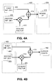
- FIG. 4A is a block diagram illustrating a construction according to the present invention in which hardware in the mouse sums input from the first input device and the second input device;
- FIG. 4B is a block diagram illustrating a construction according to the present invention in which a software driver sums which input from the first input device and the second input device;
- FIG. 5A is a block diagram illustrating a construction according to the present invention in which the scaling of an input may be adjusted from coarser to finer settings;
- FIG. 5B is a block diagram illustrating a construction according to the present invention in which inputs from a first input device and a second input device are both scaled prior to being summed by a software driver;
- FIG. 6 is a logic diagram illustrating operation according to the present invention.
- FIG. 1A is a diagrammatic top view of a first embodiment of a computer mouse 100 constructed according to the present invention.
- the computer mouse 100 includes a shell 102 constructed of plastic or another sturdy material that may be formed in the desired fashion.
- the shape of the shell 102 is shown in FIG. 1A as an example of a contemplated embodiment and should not be construed to limit the scope of the present invention.
- a tracking ball 104 extends from a lower surface of the shell 102 such that it contacts a horizontal surface upon which the mouse 100 operates. As will be described further with respect to FIG. 1B, the tracking ball 104 is coupled to transducers which translate the motion of the tracking ball 104 into electronic signals. These electronic signals are converted to produce the first input. The first input is then interpreted to cause the movement of a cursor on a computer display. In this case, the tracking ball 104 serves as a first input device for the user.
- a touch pad 106 serves as a second input device and receives touch inputs from the user via a user's finger to produce a second input.
- the touch inputs from the user's finger serves to further position the cursor on the display.
- the resolution of such cursor positioning is finer than for the first input device, the tracking ball 104 .
- scaling factors are applied to the first input and/or the second input to adjust the resolution that is obtained from each input device.
- the touch pad 106 not only receives positional information based upon the movement of the user's finger on the touch pad 106 but can receive other inputs as well.
- the tapping of a finger on the touch pad 106 may be interpreted as a click/selection of an element on the display to which the cursor location corresponds.
- double tapping of a finger on the touch pad 106 may be interpreted as a double click/selection of an element on the display to which the cursor location corresponds.
- the mouse 100 may include additional input devices as well, such as buttons 108 and 110 .
- These buttons 108 and 110 may serve to select display elements that correspond to the location of the cursor on the display. Examples of elements on a computer display include shortcuts to computer programs, web page links, text selections, pull down menus, and formatting options, among other elements. These elements may also be accessed via the touch pad 106 .
- These buttons 108 and 110 may also serve to enable mouse operations, to disable mouse operations, and to adjust mouse input scaling factors, among other operations
- the first input produced by the first input device tracking ball 104 ) and the second input produced by the second input device (touch pad 106 ) are coupled to the computer via a wired connection 112 .
- the connection to the computer may be accomplished via a wireless connection.
- the first input and the second input may be combined into a composite input prior to its transmission to the computer.
- FIG. 1B is a diagrammatic sectional side view taken along line 1 — 1 of the first embodiment of the computer mouse of FIG. 1 A.
- the tracking ball 104 resides substantially within the mouse shell 102 and contacts transducers 154 and 156 contained within a tracking ball enclosure 152 .
- These transducers 154 and 156 couple to a printed circuit board 158 or other circuitry that translates the transducer 154 and 156 inputs into the first input.
- the touch pad 106 also couples to the printed circuit board 158 , which translates the received input from the touch pad 106 into the second input.
- FIG. 2A is a diagrammatic top view of a second embodiment of a computer mouse 200 constructed according to the present invention.
- FIG. 2B is a diagrammatic sectional side view taken along line 2 — 2 of a second embodiment of the computer mouse 200 .
- the structure of FIGS. 2A and 2B is the same as that of FIGS. 1A and 1B, respectively, except for those differences described. Thus, for the common elements between FIGS. 1A, 1 B, 2 A, and 2 B, common numbering has been retained.
- the computer mouse 200 of FIGS. 2A and 2B includes, as a second input device, a second tracking ball 202 .
- the tracking ball 202 couples to transducers 252 and 254 , which translate movement of the second tracking ball 202 into electrical signals.
- These electrical signals produced by the transducers 252 and 254 are coupled to the circuit board 158 , which combines the electrical signals to form the second input.
- the circuit board 158 may combine the second input with the first input constructed from electrical signals received from the tracking ball transducers 154 and 156 and relay the combined result to the computer via wired connection 112 .
- the circuit board 158 may relay both the first input and the second input to the computer via the wired connection 112 . In this case, the computer combines the first input and the second input via appropriate scaling factors.
- FIG. 3A is a diagrammatic top view of a third embodiment of a computer mouse 300 constructed according to the present invention.
- FIG. 3B is a diagrammatic sectional side view taken along line 3 — 3 of the third embodiment of the computer mouse 300 .
- the structure of FIGS. 3A and 3B is the same as that of FIGS. 1A, 1 B, 2 A and 2 B, except for those differences 25 described. Thus, for the common elements between FIGS. 1A, 1 B, 2 A, 2 B, 3 A and 3 B, common numbering has been retained.
- the computer mouse 300 of FIGS. 3A and 3B includes, as a second input device, a joy stick 302 .
- the joy stick 302 couples to transducer 304 , which translates movement of the joy stick 302 into electrical signals.
- These electrical signals produced by the transducer 304 are coupled to the circuit board 158 , which converts the electrical signals to form the second input.
- the circuit board 158 may combine the second input with the first input constructed from electrical signals received from the tracking ball transducers 154 and 156 and relay the combined result to the computer via wired connection 112 .
- the circuit board 158 may relay both the first input and the second input to the computer via the wired connection 112 . In this case, the computer combines the first input and the second input via appropriate scaling factors.
- FIG. 4A is a block diagram illustrating a construction according to the present invention in which hardware in the mouse 402 sums the first input from the first input device 406 and the second input from the second input device 408 .
- circuitry in the mouse 402 includes scaling circuitry 412 , which scales the second input from the second input device 408 by a scaling factor 410 .
- the scaling factor may be adjusted via user input.
- the adjustment may be performed by software operation and/or hardware operation.
- the circuitry in the mouse 402 then adds the scaled second input to the first input using adding circuitry 414 .
- the combined input is then provided to the computer 404 via a mouse interface 416 .
- the scaling circuitry 412 and the adding circuitry 414 may be specialized hardware or generalized hardware that has been programmed to perform the specific functions.
- FIG. 4B is a block diagram illustrating a construction according to the present invention in which a software driver 462 sums the first input from the first input device 456 and the second input from the second input device 458 .
- circuitry in the mouse 452 simply passes the first input and the second input to the computer 454 .
- the computer 454 via a mouse interface and a mouse driver, receives the first input and the second input.
- the mouse driver scales the second input by a scaling factor 460 .
- the scaling factor may be adjusted via user input.
- the adjustment may be performed by software operation and/or hardware operation.
- the mouse drive then adds the scaled second input to the first input using an addition operation 414 .
- the mouse driver then passes the combined input to cursor control software 462 .
- hardware on the mouse interface card may perform the scaling and adding operations.
- FIG. 5A is a block diagram illustrating a construction according to the present invention in which the scaling of an input may be adjusted from coarser to finer settings.
- the input device is considered to be a tracking ball input 506 produced by a tracking ball structure 502 .
- the principles of FIG. 5A may be easily applied to a touch pad, a joy stick, a finger operated tracking ball, or other devices which produce an input having two dimensional motion represented thereby.
- a gain scaling block 504 receives the tracking ball input 506 and scales the tracking ball input 506 by a gain scaling factor 508 via scaling element 512 .
- the scaling factor is one of a plurality of discrete scaling factors. One of these scaling factors is selected via another mouse input device, e.g., a push button, a switch, or another mouse input device. The output produced by the scaling element 512 that is provided to a cursor control interface 514 is therefore scaled by the appropriate scaling factor.
- a user may use a greater scaling factor when greater cursor movement is required and a lesser scaling factor when finer cursor control is desired. Because this scaling factor is easily adjusted via mouse input, access of a software drive via more complex interaction is not required.
- FIG. 5B is a block diagram illustrating a construction according to the present invention in which mouse 552 inputs from a first input device 556 and a second input device 558 are both scaled prior to being summed by a software driver 554 .
- the mouse 552 includes both the first input device 556 and the second input device 558 and provides both a first input produced by the first input device 556 and a second input provided by the second input device 558 to the software driver 554 .
- the software driver 554 uses a scaling operation 562 to scale the first input by a first scaling factor 560 .
- the software driver 554 uses a scaling operation 566 to scale the second input by a second scaling factor 564 .
- the software driver 554 combines the output from the first scaling operation 562 and the output from the second scaling operation 566 in an adding operation 568 , the output of which is provided to a cursor control operation 570 .
- FIG. 6 is a logic diagram illustrating operation according to the present invention. The operations of FIG. 6 are described with reference to a mouse driver. However, some of these operations may also be performed by hardware resident in a computer mouse and/or in a mouse interface. Operation of the mouse remains in an idle operation (step 602 ) until the various operations described herein occur. Of course, the mouse may perform other operations that are not described with reference to FIG. 6 .
- the mouse receives cursor control input from a user (step 604 ).
- the mouse driver receives a first input from a first input device (step 606 ).
- the mouse driver also receives a second input from a second input device (step 608 ).
- the mouse driver then sums and scales the first input and the second input (step 610 ). These scaling and summing operations are consistent with those described with reference to FIGS. 4A, 4 B, 5 A and 5 B.
- the mouse driver forwards the result to the computer for cursor control operation (step 612 ). From step 612 , operation returns to step 602 .
- the user toggles the scaling factor for one of the input devices.
- FIG. 5A discloses toggling of the scaling factor of an input device among a plurality of discrete scaling factors.
- the mouse driver receives the toggle input from the user (step 616 ).
- the mouse driver increments the scaling factor to the next higher scaling position (step 618 ).
- the mouse driver decrements the scaling factor to the next lesser scaling position. From step 618 , operation returns to step 602 .
- the mouse driver supports altering functions of the mouse (step 620 ). Such functions may include whether an input is scaled, whether an input scaling factor may be toggled, whether multiple inputs are used for cursor control, the operation provided by a mouse button, among other functions.
- the mouse driver receives the new function operation (step 622 ) and adjusts the operation of the mouse accordingly (step 624 ). From step 624 , operation returns to step 602 .
Abstract
A mouse provides multiple cursor control input devices. A first input device is a tracking ball. The second input device may be a tracking ball, a finger pad, or a joy stick, among other input devices. The second input device provides a secondary control of cursor movement that is combined with the input of the first input device to provide full cursor control. In one embodiment, the second input is scaled by a scaling factor and then combined with the first input. In another embodiment, both the first input and the second input are scaled before they are combined. In another mouse, a single input is provided that is scaled by one of a plurality of scaling factors. The scaling factor may be altered to another one of the plurality of scaling factors via mouse input, for example a button input.
Description
1. Technical Field
The present invention relates generally to digital computers; and more particularly to a mouse used to position a cursor on the display of a digital computer.
2. Related Art
Digital computers have been known in the art for years. Personal digital computers typically include a case, a video display, and one or more input/output devices. The case typically includes a power supply, a cooling fan, a motherboard, interface ports, peripheral cards, a disk drive, and other components. Contained on the motherboard are a processor, memory, a processor chip set, and one or more peripheral buses. The peripheral cards interface input/output devices with the motherboard via the peripheral buses. Other input/output devices may couple directly to the motherboard via appropriate connectors, e.g., devices coupled via a parallel port, devices coupled via a serial port, and devices coupled via a USB.
Generally speaking, input/output devices receive input from a user or another source and/or provide output to a user or anther source. Keyboards and computer mice are typically considered input devices because they receive input from a user but provide no output to the user. Typical monitors are considered output devices because they provide output to the user but receive no input from the user. Touch sensitive monitors however, do receive input from a user and are also considered an input device. Audio speakers are output devices while audio microphones are input devices.
A great difficulty in the design and operation of personal computers relates to user interfaces. Such is the case because the interaction of humans with computers is a primary purpose of computers. The keyboard has been the primary user input device since the advent of personal computers. The computer mouse has become a popular input device due to its ease of use. The mouse allows a user to position a cursor on the display by altering the physical position of the mouse. Typically, the mouse resides on a horizontal surface, such as a mouse pad resting on a desktop, and contacts the horizontal surface. A tracking ball contacts the mouse pad and, when the position of the mouse is altered, the tracking ball changes its orientation with respect to the mouse. Electronics contained in the mouse sense the change in orientation of the tracking ball within the mouse and translate this into electronic signals. These electronic signals are transmitted to the motherboard via an interface, processed by software executing on the computer and result in a change in position of the cursor on the display.
Additional input devices on the mouse, such as push buttons, allow for additional operations, such as item selection, text highlighting, and dragging/dropping, for example. A mouse wheel may also be included that allows a user to scroll the computer's display. With some mice, push buttons may be programmed to execute other functions as well, such as double click operations with a single button push.
Mice are designed to accommodate the range of motion of a user's arm and/or wrist. The user's arm and/or wrist provide a relatively large range of motion. To provide full screen cursor control, mice are designed so that a reasonable range of motion of the mouse provides full-screen cursor movement. However, this design makes fine cursor movement difficult. While fine cursor positioning is available by programming the mouse to have a lesser range of operation, the benefit of full screen cursor movement is defeated with these settings. Further, most users cannot provide fine levels of input with their arm/or wrist. Thus, it is difficult for most users to control the fine motion of a cursor using a mouse.
Thus, there is a need in the art for a mouse that provides full-screen cursor movement but at the same time allows for fine positioning of the cursor.
Thus, to overcome the shortcomings of the prior systems, among other shortcomings, a mouse constructed according to the present invention provides multiple cursor control input devices. A first input device is the traditional tracking ball input that operates when the position of the mouse is altered with respect to a surface upon which it resides. A second input device resides upon a surface of the mouse that is accessible with one or more of the user's fingers. This second input device may be a tracking ball, a finger pad, or a joy stick, among other input devices. This second input device provides a secondary control of cursor movement that is combined with the input of the first input device to provide full cursor control.
In a described operation, the first input device provides coarse cursor control while the second input device provides fine cursor control. This configuration compliments the motor control available with a user's hand and fingers. The user's hand/wrist has coarser motor control than does the user's fingers. Thus, the first input device is operated by motion of the user's hand or wrist and provides coarse positioning of the cursor. Further, the second input device is operated by one or more fingers of the user and provides fine cursor positioning. Thus, while the first input device corresponds to the coarse motor control of the user's hand/wrist in positioning the cursor, the second input device corresponds to the fine motor control of the user's fingers in finely positioning the cursor.
In another embodiment of the present invention, the user provides input only via the first input device. However, a button on the mouse (or other toggling mechanism) adjusts the gain or scaling of the first input device between a coarser positioning and a finer positioning. In this fashion, the user may coarsely position the cursor on the display using the coarser setting, adjust the scaling of the input device, and finely position the cursor on the display using the finer setting.
Moreover, other aspects of the present invention will become apparent with further reference to the drawings and specification, which follow.
A better understanding of the present invention can be obtained when the following detailed description of the preferred embodiment is considered in conjunction with the following drawings, in which:
FIG. 1A is a diagrammatic top view of a first embodiment of a computer mouse constructed according to the present invention;
FIG. 1B is a diagrammatic sectional side view taken along line 1—1 of a first embodiment of a computer mouse constructed according to the present invention;
FIG. 2A is a diagrammatic top view of a second embodiment of a computer mouse constructed according to the present invention;
FIG. 2B is a diagrammatic sectional side view taken along line 2—2 of a second embodiment of a computer mouse constructed according to the present invention;
FIG. 3A is a diagrammatic top view of a third embodiment of a computer mouse constructed according to the present invention;
FIG. 3B is a diagrammatic sectional side view taken along line 3—3 of a third embodiment of a computer mouse constructed according to the present invention;
FIG. 4A is a block diagram illustrating a construction according to the present invention in which hardware in the mouse sums input from the first input device and the second input device;
FIG. 4B is a block diagram illustrating a construction according to the present invention in which a software driver sums which input from the first input device and the second input device;
FIG. 5A is a block diagram illustrating a construction according to the present invention in which the scaling of an input may be adjusted from coarser to finer settings;
FIG. 5B is a block diagram illustrating a construction according to the present invention in which inputs from a first input device and a second input device are both scaled prior to being summed by a software driver; and
FIG. 6 is a logic diagram illustrating operation according to the present invention.
FIG. 1A is a diagrammatic top view of a first embodiment of a computer mouse 100 constructed according to the present invention. The computer mouse 100 includes a shell 102 constructed of plastic or another sturdy material that may be formed in the desired fashion. The shape of the shell 102 is shown in FIG. 1A as an example of a contemplated embodiment and should not be construed to limit the scope of the present invention.
Various user input devices extend from the shell 102 of the mouse 100. A tracking ball 104 extends from a lower surface of the shell 102 such that it contacts a horizontal surface upon which the mouse 100 operates. As will be described further with respect to FIG. 1B, the tracking ball 104 is coupled to transducers which translate the motion of the tracking ball 104 into electronic signals. These electronic signals are converted to produce the first input. The first input is then interpreted to cause the movement of a cursor on a computer display. In this case, the tracking ball 104 serves as a first input device for the user.
A touch pad 106 serves as a second input device and receives touch inputs from the user via a user's finger to produce a second input. The touch inputs from the user's finger serves to further position the cursor on the display. However, the resolution of such cursor positioning is finer than for the first input device, the tracking ball 104. As will be further described, scaling factors are applied to the first input and/or the second input to adjust the resolution that is obtained from each input device.
The touch pad 106 not only receives positional information based upon the movement of the user's finger on the touch pad 106 but can receive other inputs as well. For example, the tapping of a finger on the touch pad 106 may be interpreted as a click/selection of an element on the display to which the cursor location corresponds. Further, double tapping of a finger on the touch pad 106 may be interpreted as a double click/selection of an element on the display to which the cursor location corresponds.
The mouse 100 may include additional input devices as well, such as buttons 108 and 110. These buttons 108 and 110 may serve to select display elements that correspond to the location of the cursor on the display. Examples of elements on a computer display include shortcuts to computer programs, web page links, text selections, pull down menus, and formatting options, among other elements. These elements may also be accessed via the touch pad 106. These buttons 108 and 110 may also serve to enable mouse operations, to disable mouse operations, and to adjust mouse input scaling factors, among other operations
The first input produced by the first input device tracking ball 104) and the second input produced by the second input device (touch pad 106) are coupled to the computer via a wired connection 112. However, in another embodiment, the connection to the computer may be accomplished via a wireless connection. Further, in either case, the first input and the second input may be combined into a composite input prior to its transmission to the computer.
FIG. 1B is a diagrammatic sectional side view taken along line 1—1 of the first embodiment of the computer mouse of FIG. 1A. As is shown, the tracking ball 104 resides substantially within the mouse shell 102 and contacts transducers 154 and 156 contained within a tracking ball enclosure 152. These transducers 154 and 156 couple to a printed circuit board 158 or other circuitry that translates the transducer 154 and 156 inputs into the first input. The touch pad 106 also couples to the printed circuit board 158, which translates the received input from the touch pad 106 into the second input.
FIG. 2A is a diagrammatic top view of a second embodiment of a computer mouse 200 constructed according to the present invention. FIG. 2B is a diagrammatic sectional side view taken along line 2—2 of a second embodiment of the computer mouse 200. The structure of FIGS. 2A and 2B is the same as that of FIGS. 1A and 1B, respectively, except for those differences described. Thus, for the common elements between FIGS. 1A, 1B, 2A, and 2B, common numbering has been retained.
As compared to the computer mouse 100 of FIGS. 1A and 1B, the computer mouse 200 of FIGS. 2A and 2B includes, as a second input device, a second tracking ball 202. The tracking ball 202 couples to transducers 252 and 254, which translate movement of the second tracking ball 202 into electrical signals. These electrical signals produced by the transducers 252 and 254 are coupled to the circuit board 158, which combines the electrical signals to form the second input. The circuit board 158 may combine the second input with the first input constructed from electrical signals received from the tracking ball transducers 154 and 156 and relay the combined result to the computer via wired connection 112. Alternately, the circuit board 158 may relay both the first input and the second input to the computer via the wired connection 112. In this case, the computer combines the first input and the second input via appropriate scaling factors.
FIG. 3A is a diagrammatic top view of a third embodiment of a computer mouse 300 constructed according to the present invention. FIG. 3B is a diagrammatic sectional side view taken along line 3—3 of the third embodiment of the computer mouse 300. The structure of FIGS. 3A and 3B is the same as that of FIGS. 1A, 1B, 2A and 2B, except for those differences 25 described. Thus, for the common elements between FIGS. 1A, 1B, 2A, 2B, 3A and 3B, common numbering has been retained.
As compared to the computer mouse 100 of FIGS. 1A and 1B, and the computer mouse 200 of FIGS. 2A and 2B, the computer mouse 300 of FIGS. 3A and 3B includes, as a second input device, a joy stick 302. The joy stick 302 couples to transducer 304, which translates movement of the joy stick 302 into electrical signals. These electrical signals produced by the transducer 304 are coupled to the circuit board 158, which converts the electrical signals to form the second input. The circuit board 158 may combine the second input with the first input constructed from electrical signals received from the tracking ball transducers 154 and 156 and relay the combined result to the computer via wired connection 112. Alternately, the circuit board 158 may relay both the first input and the second input to the computer via the wired connection 112. In this case, the computer combines the first input and the second input via appropriate scaling factors.
FIG. 4A is a block diagram illustrating a construction according to the present invention in which hardware in the mouse 402 sums the first input from the first input device 406 and the second input from the second input device 408. In the embodiment of FIG. 4A, circuitry in the mouse 402 includes scaling circuitry 412, which scales the second input from the second input device 408 by a scaling factor 410.
The scaling factor may be adjusted via user input. The adjustment may be performed by software operation and/or hardware operation. The circuitry in the mouse 402 then adds the scaled second input to the first input using adding circuitry 414. The combined input is then provided to the computer 404 via a mouse interface 416. The scaling circuitry 412 and the adding circuitry 414 may be specialized hardware or generalized hardware that has been programmed to perform the specific functions.
FIG. 4B is a block diagram illustrating a construction according to the present invention in which a software driver 462 sums the first input from the first input device 456 and the second input from the second input device 458. In the embodiment of FIG. 4B, circuitry in the mouse 452 simply passes the first input and the second input to the computer 454. The computer 454, via a mouse interface and a mouse driver, receives the first input and the second input. The mouse driver scales the second input by a scaling factor 460.
The scaling factor may be adjusted via user input. The adjustment may be performed by software operation and/or hardware operation. The mouse drive then adds the scaled second input to the first input using an addition operation 414. The mouse driver then passes the combined input to cursor control software 462. In an alternate construction, hardware on the mouse interface card may perform the scaling and adding operations.
FIG. 5A is a block diagram illustrating a construction according to the present invention in which the scaling of an input may be adjusted from coarser to finer settings. In the description of FIG. 5A, the input device is considered to be a tracking ball input 506 produced by a tracking ball structure 502. However, the principles of FIG. 5A may be easily applied to a touch pad, a joy stick, a finger operated tracking ball, or other devices which produce an input having two dimensional motion represented thereby.
A gain scaling block 504 receives the tracking ball input 506 and scales the tracking ball input 506 by a gain scaling factor 508 via scaling element 512. According to the teachings of FIG. 5A, however, the scaling factor, is one of a plurality of discrete scaling factors. One of these scaling factors is selected via another mouse input device, e.g., a push button, a switch, or another mouse input device. The output produced by the scaling element 512 that is provided to a cursor control interface 514 is therefore scaled by the appropriate scaling factor.
By applying one of a plurality of scaling factors via a simple scaling factor adjustment, a user may use a greater scaling factor when greater cursor movement is required and a lesser scaling factor when finer cursor control is desired. Because this scaling factor is easily adjusted via mouse input, access of a software drive via more complex interaction is not required.
FIG. 5B is a block diagram illustrating a construction according to the present invention in which mouse 552 inputs from a first input device 556 and a second input device 558 are both scaled prior to being summed by a software driver 554. The mouse 552 includes both the first input device 556 and the second input device 558 and provides both a first input produced by the first input device 556 and a second input provided by the second input device 558 to the software driver 554. The software driver 554 uses a scaling operation 562 to scale the first input by a first scaling factor 560. Likewise, the software driver 554 uses a scaling operation 566 to scale the second input by a second scaling factor 564. The software driver 554 combines the output from the first scaling operation 562 and the output from the second scaling operation 566 in an adding operation 568, the output of which is provided to a cursor control operation 570.
FIG. 6 is a logic diagram illustrating operation according to the present invention. The operations of FIG. 6 are described with reference to a mouse driver. However, some of these operations may also be performed by hardware resident in a computer mouse and/or in a mouse interface. Operation of the mouse remains in an idle operation (step 602) until the various operations described herein occur. Of course, the mouse may perform other operations that are not described with reference to FIG. 6.
As a first operation, the mouse receives cursor control input from a user (step 604). When this occurs, the mouse driver receives a first input from a first input device (step 606). The mouse driver also receives a second input from a second input device (step 608). The mouse driver then sums and scales the first input and the second input (step 610). These scaling and summing operations are consistent with those described with reference to FIGS. 4A, 4B, 5A and 5B. Finally, the mouse driver forwards the result to the computer for cursor control operation (step 612). From step 612, operation returns to step 602.
At step 614, the user toggles the scaling factor for one of the input devices. For example, FIG. 5A discloses toggling of the scaling factor of an input device among a plurality of discrete scaling factors. When, such toggling operation is initiated, the mouse driver receives the toggle input from the user (step 616). In response, the mouse driver increments the scaling factor to the next higher scaling position (step 618). In an alternate operation, the mouse driver decrements the scaling factor to the next lesser scaling position. From step 618, operation returns to step 602.
Finally, the mouse driver supports altering functions of the mouse (step 620). Such functions may include whether an input is scaled, whether an input scaling factor may be toggled, whether multiple inputs are used for cursor control, the operation provided by a mouse button, among other functions. The mouse driver receives the new function operation (step 622) and adjusts the operation of the mouse accordingly (step 624). From step 624, operation returns to step 602.
The invention disclosed herein is susceptible to various modifications and alternative forms. Specific embodiments therefor have been shown by way of example in the drawings and detailed description. It should be understood, however, that the drawings and detailed description thereto are not intended to limit the invention to the particular form disclosed, but on the contrary, the invention is to cover all modifications, equivalents and alternatives falling within the spirit and scope of the present invention as defined by the claims.
Claims (21)
1. A computer mouse comprising:
a mouse shell having a top portion and a bottom portion, wherein the top portion includes an anterior portion and a posterior portion;
a first cursor positioning input device that controls the positioning of a two-dimensional cursor in a two-dimensional screen area wherein the first cursor positioning input device produces a first input in response to motion of the mouse shell relative to a stationary reference;
a second cursor positioning input device substantially centrally located on the anterior portion of the top portion of the mouse shell and that controls the positioning of the two-dimensional cursor in the two-dimensional screen area and wherein the second cursor positioning input device produces a second input in response to motion of the second cursor positioning input device relative to the mouse shell; and
circuitry operably coupled to the first cursor positioning input, the second cursor positioning input, and a coupled computer, wherein the circuitry scales the second input by a scaling factor to produce a scaled second put, wherein the circuitry combines the scaled second input with the first input to produce a composite output, and wherein the circuitry provides the composite output to the coupled computer for two-dimensional cursor positioning in the two-dimensional screen area.
2. The computer mouse of claim 1 , wherein the scaling factor is selected such that user input to the first cursor positioning input device produces coarse two-dimensional cursor positioning and user to the second cursor positioning input produces fine two-dimensional cursor positioning.
3. The computer mouse of claim 1 , wherein the first cursor positioning input device is a tracking ball.
4. The computer mouse of claim 1 , wherein the second cursor positioning input device is a tracking ball.
5. The computer mouse of claim 1 , wherein the second cursor positioning input device is a touch pad.
6. The computer mouse of claim 1 , wherein the second cursor positioning input device is a joystick.
7. The computer mouse of claim 5 , wherein the touch pad is centrally located on the anterior portion of the top portion of the mouse shell.
8. The computer mouse of claim 1 , wherein the composite output is provided to the coupled computer in a standardized format such that it is indistinguishable from a signal provided to the coupled computer from a mouse having a single two-dimensional cursor positioning input.
9. The computer mouse of claim 1 , wherein the scaling factor is one of a plurality of scaling factors.
10. The computer mouse of claim 9 , wherein:
the mouse further comprises a toggle input; and
a toggling of the toggle input causes the scaling factor to be altered from a first scaling factor of the plurality of scaling factors to a second scaling factor of the plurality of scaling factors.
11. A computer mouse comprising:
a mouse shell having a top portion and a bottom portion, wherein the top portion includes an anterior portion and a postror portion;
a first cursor positioning input device that controls the positioning of a two-dimensional cursor in a two-dimensional screen area, when the first cursor positioning input device produces a first input in response to motion of the mouse shell relative to a stationary reference;
a touch pad that is substantially centrally located on the anterior portion of the top portion of the mouse shell and that controls the positioning of the two-dimensional cursor in the two-dimensional screen area, wherein the touch pad is readily accessible to an index finger of a user of the mouse when the user's palm resides upon the anterior portion of the mouse shell, and wherein the touch pad produces a second input in response to motive touch having motion relative to the mouse shell;
circuitry operably coupled to the first cursor positioning input, the touch pad, and a coupled computer, wherein the circuitry scales the second input by a scaling factor to produce a said second input, wherein the circuitry combines the scaled second input with the first input to produce a composite output, and wherein the circuitry provides the composite output to the coupled computer for two-dimensional cursor positioning in the two-dimensional screen area; and
wherein the scaling factor is selected such that user input to the first cursor positioning input device produces coarse two-dimensional cursor positioning and user to the second cursor positioning input produces fine two-dimensional cursor positioning.
12. The computer mouse of claim 11 , wherein the first cursor positioning input device is a tracking ball.
13. The computer mouse of claim 11 , wherein the composite output is provided to the coupled computer in a standardized format such that it is indistinguishable from a signal provided to the coupled computer from a mouse having a single two-dimensional cursor positioning input.
14. The computer mouse of claim 11 , wherein the scaling factor is one of a plurality of scaling factors.
15. The computer mouse of claim 14 , wherein:
the mouse further comprises a toggle input; and
a toggling of the toggle input causes the scaling factor to be altered from a first scaling factor of the plurality of scaling factors to a second scaling factor of the plurality of scaling factors.
16. A computer mouse comprising:
a mouse shell having a top portion and a bottom portion, wherein the top portion includes an anterior portion and a posterior portion;
a first cursor positioning input device that controls the positioning of a two-dimensional cursor in a two-dimensional screen area, wherein the first cursor positioning input device produces a first input in response to motion of the mouse shell relative to a stationary reference;
a touch pad that is substantially centrally located on the anterior portion of he top portion of the mouse shell and that controls the positioning of the two-dimensional cursor in the two-dimensional screen area, wherein the touch pad is readily accessible to an index finger of a user of the mouse when the user's palm resides upon the anterior portion of the mouse shell, and wherein the touch pad produces a second input in response to notive touch having motion relative to the mouse shell;
circuitry operably coupled to the first cursor positioning input, the touch pad, and a coupled computer, wherein the circuitry scales the second input by a scaling factor to produce a scaled second input, wherein the circuitry combines the scaled second input with the first input to produce a composite output, and wherein the circuitry provides the composite output to the coupled computer for two-dimensional cursor positioning in the two-dimensional screen area;
wherein the scaling factor is selected such that user input to the first cursor positioning input device produces coarse two-dimensional cursor positioning and user to the second cursor positioning input produces fine two-dimensional cursor positioning; and
wherein the scaling factor may be chosen from a plurality of possible scaling factors.
17. The computer mouse of claim 16 , wherein the first cursor positioning input device is a tracking ball.
18. The computer mouse of claim 16 , wherein the composite output is provided to the coupled computer in a standardized format such that it is indistinguishable from a signal provided to the coupled computer from a mouse having a single two-dimensional cursor positioning input.
19. The computer mouse of claim 16 , wherein:
the mouse further comprises a toggle input; and
a toggling of the toggle input causes the scaling factor to be altered from a first scaling factor of the plurality of scaling factors to a second scaling factor of the plurality of scaling factors.
20. A computer mouse comprising:
a mouse shell having a top portion and a bottom portion, wherein the top portion includes an anterior portion and a posterior portion;
a first cursor positioning input device that controls the positioning of a two-dimensional cursor in a two-dimensional screen area wherein the first cursor positioning input device produces a first input in response to motion of the mouse shell relative to a stationary reference;
a touch pad that is substantially centrally located on the anterior portion of the top portion of the mouse shell and that controls the positioning of the two-dimensional cursor in the two-dimensional screen area, wherein the touch pad is readily accessible to all index finger of a user of the mouse when the user's palm resides upon the anterior portion of the mouse shell, and wherein the touch pad produces a second input in response to motive touch having motion relative to the mouse shell;
circuitry operably coupled to the fist cursor positioning input, the touch pad, and a coupled computer, wherein the circuitry scales the second input by a scaling factor to produce a scaled second input, wherein the circuitry combines the scaled second input with the first input to produce a composite output and when the circuitry provides the composite output to the coupled computer for two-dimensional cursor positioning in the two-dimensional screen area;
wherein the scaling factor is selected such that user input to the first cursor positioning input device produces coarse two-dimensional cursor positioning and user to the second cursor position input produces fine two-dimensional cursor positioning;
wherein the scaling factor may be chosen from a plurality of scaling factors; and
wherein the composite output is provided to the coupled computer in a standardized format such that it is indistinguishable from a signal provided to the coupled computer from a mouse having a singe two-dimensional cursor positioning input.
21. The computer mouse of claim 20 , wherein:
the mouse further comprises a toggle input; and
a toggling of the toggle input causes the scaling factor to be altered from a first scaling factor of the plurality of scaling factor of the plurality of scaling factors.
Priority Applications (1)
| Application Number | Priority Date | Filing Date | Title |
|---|---|---|---|
| US09/552,926 US6489948B1 (en) | 2000-04-20 | 2000-04-20 | Computer mouse having multiple cursor positioning inputs and method of operation |
Applications Claiming Priority (1)
| Application Number | Priority Date | Filing Date | Title |
|---|---|---|---|
| US09/552,926 US6489948B1 (en) | 2000-04-20 | 2000-04-20 | Computer mouse having multiple cursor positioning inputs and method of operation |
Publications (1)
| Publication Number | Publication Date |
|---|---|
| US6489948B1 true US6489948B1 (en) | 2002-12-03 |
Family
ID=24207383
Family Applications (1)
| Application Number | Title | Priority Date | Filing Date |
|---|---|---|---|
| US09/552,926 Expired - Fee Related US6489948B1 (en) | 2000-04-20 | 2000-04-20 | Computer mouse having multiple cursor positioning inputs and method of operation |
Country Status (1)
| Country | Link |
|---|---|
| US (1) | US6489948B1 (en) |
Cited By (60)
| Publication number | Priority date | Publication date | Assignee | Title |
|---|---|---|---|---|
| US20020196234A1 (en) * | 2001-06-25 | 2002-12-26 | Gray Robin S. | Computer mouse system and method of using |
| US20030201977A1 (en) * | 2002-04-30 | 2003-10-30 | Hassig Alan C. | Computer mouse with integral keypad |
| US20040041787A1 (en) * | 2002-08-28 | 2004-03-04 | Graves Robert A. | Method and apparatus for a hybrid pointing device used with a data processing system |
| US6727889B2 (en) * | 2001-09-14 | 2004-04-27 | Stephen W. Shaw | Computer mouse input device with multi-axis palm control |
| US20040140954A1 (en) * | 2003-01-14 | 2004-07-22 | Faeth Michael Gene | Two handed computer input device |
| US20040243724A1 (en) * | 2001-09-21 | 2004-12-02 | Bernd Gombert | Combined position and torque sensor |
| US20050001786A1 (en) * | 2001-11-12 | 2005-01-06 | Jensen Ken Alvin | Control device (mouse) for computer |
| US20050083297A1 (en) * | 2003-10-17 | 2005-04-21 | Duncan Thomas M. | Ergonomically designed computer gaming device |
| US20050099392A1 (en) * | 2003-09-22 | 2005-05-12 | Muneki Ishida | Mouse having scrolling function |
| US20050156890A1 (en) * | 2003-12-31 | 2005-07-21 | Asustek Computer Inc. | Pointing device having a loop-like touch pad for implementing a scrolling function |
| US20050179655A1 (en) * | 2004-02-13 | 2005-08-18 | Ludwig Lester F. | Electronic document editing employing multiple cursors |
| US20050190144A1 (en) * | 2004-02-26 | 2005-09-01 | Microsoft Corporation | Multi-modal navigation in a graphical user interface computing system |
| WO2005106640A1 (en) * | 2004-04-30 | 2005-11-10 | Aleksandr Nikolaevich Rukin | Cursor control device |
| US20060007138A1 (en) * | 2003-01-14 | 2006-01-12 | Faeth Michael G | Pointing stick with function pad for two handed operation |
| US20060021819A1 (en) * | 2004-07-30 | 2006-02-02 | Caterpillar Inc. | Work machine tool control console |
| US20060239471A1 (en) * | 2003-08-27 | 2006-10-26 | Sony Computer Entertainment Inc. | Methods and apparatus for targeted sound detection and characterization |
| US20060244726A1 (en) * | 2004-12-08 | 2006-11-02 | Paten Wireless Technology Inc. | Wireless input device |
| EP1727028A2 (en) * | 2005-05-25 | 2006-11-29 | Avago Technologies General IP (Singapore) Pte. Ltd | Dual-positioning controller and method for controlling an indicium on a display of an electronic device |
| US20060269073A1 (en) * | 2003-08-27 | 2006-11-30 | Mao Xiao D | Methods and apparatuses for capturing an audio signal based on a location of the signal |
| US20060271886A1 (en) * | 2005-05-25 | 2006-11-30 | Wenstrand John S | Character entry system and method for electronic devices |
| US20070015559A1 (en) * | 2002-07-27 | 2007-01-18 | Sony Computer Entertainment America Inc. | Method and apparatus for use in determining lack of user activity in relation to a system |
| WO2007130793A2 (en) * | 2006-05-04 | 2007-11-15 | Sony Computer Entertainment America Inc. | Obtaining input for controlling execution of a game program |
| US20070265078A1 (en) * | 2006-05-09 | 2007-11-15 | Alvin Yu | Steering wheel control assembly with speedy control key(s) |
| US20080098448A1 (en) * | 2006-10-19 | 2008-04-24 | Sony Computer Entertainment America Inc. | Controller configured to track user's level of anxiety and other mental and physical attributes |
| US20080096654A1 (en) * | 2006-10-20 | 2008-04-24 | Sony Computer Entertainment America Inc. | Game control using three-dimensional motions of controller |
| US20080100571A1 (en) * | 2006-10-28 | 2008-05-01 | Mills Percival Christoffel | Human interface device |
| US20080274804A1 (en) * | 2002-07-27 | 2008-11-06 | Sony Computer Entertainment America Inc. | Method and system for adding a new player to a game in response to controller activity |
| US20080284730A1 (en) * | 2007-05-15 | 2008-11-20 | David Fleck | Device, method, and computer readable medium for mapping a graphics tablet to an associated display |
| EP1644814B1 (en) * | 2003-07-01 | 2008-12-17 | EM Microelectronic-Marin SA | Displacement data post-processing and reporting in an optical pointing device |
| US20090122146A1 (en) * | 2002-07-27 | 2009-05-14 | Sony Computer Entertainment Inc. | Method and apparatus for tracking three-dimensional movements of an object using a depth sensing camera |
| US20090153500A1 (en) * | 2007-12-17 | 2009-06-18 | Samsung Electronics Co., Ltd. | Dual pointing device and method based on 3-D motion and touch sensors |
| US20100045602A1 (en) * | 2008-08-25 | 2010-02-25 | International Business Machines Corporation | Position input device with anchorage |
| US20100066670A1 (en) * | 2008-09-18 | 2010-03-18 | Apple Inc. | Force sensing for fine tracking control of mouse cursor |
| US20100066669A1 (en) * | 2008-09-18 | 2010-03-18 | Apple Inc. | Using measurement of lateral force for a tracking input device |
| US7803050B2 (en) | 2002-07-27 | 2010-09-28 | Sony Computer Entertainment Inc. | Tracking device with sound emitter for use in obtaining information for controlling game program execution |
| US7850526B2 (en) | 2002-07-27 | 2010-12-14 | Sony Computer Entertainment America Inc. | System for tracking user manipulations within an environment |
| US20100315336A1 (en) * | 2009-06-16 | 2010-12-16 | Microsoft Corporation | Pointing Device Using Proximity Sensing |
| US7854655B2 (en) * | 2002-07-27 | 2010-12-21 | Sony Computer Entertainment America Inc. | Obtaining input for controlling execution of a game program |
| KR101020509B1 (en) | 2006-05-04 | 2011-03-09 | 소니 컴퓨터 엔터테인먼트 아메리카 엘엘씨 | Obtaining input for controlling execution of a program |
| US7918733B2 (en) | 2002-07-27 | 2011-04-05 | Sony Computer Entertainment America Inc. | Multi-input game control mixer |
| US20110141021A1 (en) * | 2009-12-14 | 2011-06-16 | Stmicroelectronics (Research & Development) Limited | High precision optical navigation device |
| US8139793B2 (en) | 2003-08-27 | 2012-03-20 | Sony Computer Entertainment Inc. | Methods and apparatus for capturing audio signals based on a visual image |
| US8160269B2 (en) | 2003-08-27 | 2012-04-17 | Sony Computer Entertainment Inc. | Methods and apparatuses for adjusting a listening area for capturing sounds |
| CN102486689A (en) * | 2010-12-06 | 2012-06-06 | 联想(北京)有限公司 | Input method and terminal |
| US8310446B1 (en) * | 2006-08-25 | 2012-11-13 | Rockwell Collins, Inc. | System for integrated coarse and fine graphical object positioning |
| US8310656B2 (en) | 2006-09-28 | 2012-11-13 | Sony Computer Entertainment America Llc | Mapping movements of a hand-held controller to the two-dimensional image plane of a display screen |
| US8313380B2 (en) | 2002-07-27 | 2012-11-20 | Sony Computer Entertainment America Llc | Scheme for translating movements of a hand-held controller into inputs for a system |
| WO2012158895A2 (en) | 2011-05-18 | 2012-11-22 | Microsoft Corporation | Disambiguating intentional and incidental contact and motion in multi-touch pointing devices |
| US20120326965A1 (en) * | 2008-07-18 | 2012-12-27 | Apple Inc. | Methods and apparatus for processing combinations of kinematical inputs |
| US8781151B2 (en) | 2006-09-28 | 2014-07-15 | Sony Computer Entertainment Inc. | Object detection using video input combined with tilt angle information |
| US8797260B2 (en) | 2002-07-27 | 2014-08-05 | Sony Computer Entertainment Inc. | Inertially trackable hand-held controller |
| US20150029099A1 (en) * | 2013-07-26 | 2015-01-29 | Tianjin Funayuanchuang Technology Co.,Ltd. | Method for controlling touch and motion sensing pointing device |
| US9174119B2 (en) | 2002-07-27 | 2015-11-03 | Sony Computer Entertainement America, LLC | Controller for providing inputs to control execution of a program when inputs are combined |
| US9393487B2 (en) | 2002-07-27 | 2016-07-19 | Sony Interactive Entertainment Inc. | Method for mapping movements of a hand-held controller to game commands |
| US9639187B2 (en) | 2008-09-22 | 2017-05-02 | Apple Inc. | Using vibration to determine the motion of an input device |
| CN101484221B (en) * | 2006-05-04 | 2017-05-03 | 美国索尼电脑娱乐公司 | Obtaining input for controlling execution of a game program |
| US20180196531A1 (en) * | 2017-01-06 | 2018-07-12 | Primax Electronics Ltd. | Air pressure sensing type mouse |
| US10359868B2 (en) * | 2012-10-29 | 2019-07-23 | Pixart Imaging Incorporation | Method and apparatus for controlling object movement on screen |
| USRE48417E1 (en) | 2006-09-28 | 2021-02-02 | Sony Interactive Entertainment Inc. | Object direction using video input combined with tilt angle information |
| US11656695B2 (en) * | 2018-12-31 | 2023-05-23 | Oahwip B.V. | Computer mouse for different modes of use |
Citations (3)
| Publication number | Priority date | Publication date | Assignee | Title |
|---|---|---|---|---|
| US4891632A (en) * | 1988-01-20 | 1990-01-02 | King Phoenix Co., Ltd. | Computer graphic drawing apparatus with coarse and fine controls |
| US4931781A (en) * | 1982-02-03 | 1990-06-05 | Canon Kabushiki Kaisha | Cursor movement control key switch |
| US6184869B1 (en) * | 1998-09-30 | 2001-02-06 | Matter And Motion, Inc. | Computer input device having multiple multi-dimensional detection devices |
-
2000
- 2000-04-20 US US09/552,926 patent/US6489948B1/en not_active Expired - Fee Related
Patent Citations (3)
| Publication number | Priority date | Publication date | Assignee | Title |
|---|---|---|---|---|
| US4931781A (en) * | 1982-02-03 | 1990-06-05 | Canon Kabushiki Kaisha | Cursor movement control key switch |
| US4891632A (en) * | 1988-01-20 | 1990-01-02 | King Phoenix Co., Ltd. | Computer graphic drawing apparatus with coarse and fine controls |
| US6184869B1 (en) * | 1998-09-30 | 2001-02-06 | Matter And Motion, Inc. | Computer input device having multiple multi-dimensional detection devices |
Cited By (113)
| Publication number | Priority date | Publication date | Assignee | Title |
|---|---|---|---|---|
| US20020196234A1 (en) * | 2001-06-25 | 2002-12-26 | Gray Robin S. | Computer mouse system and method of using |
| US6970159B2 (en) * | 2001-06-25 | 2005-11-29 | Gray Robin S | Mouse printing device with integrated touch pad buttons |
| US6727889B2 (en) * | 2001-09-14 | 2004-04-27 | Stephen W. Shaw | Computer mouse input device with multi-axis palm control |
| US20040243724A1 (en) * | 2001-09-21 | 2004-12-02 | Bernd Gombert | Combined position and torque sensor |
| US20050001786A1 (en) * | 2001-11-12 | 2005-01-06 | Jensen Ken Alvin | Control device (mouse) for computer |
| US7176882B2 (en) * | 2001-11-12 | 2007-02-13 | Ken Alvin Jenssen | Hand held control device with dual mode joystick for pointing and scrolling |
| US20030201977A1 (en) * | 2002-04-30 | 2003-10-30 | Hassig Alan C. | Computer mouse with integral keypad |
| US9682320B2 (en) | 2002-07-22 | 2017-06-20 | Sony Interactive Entertainment Inc. | Inertially trackable hand-held controller |
| US7803050B2 (en) | 2002-07-27 | 2010-09-28 | Sony Computer Entertainment Inc. | Tracking device with sound emitter for use in obtaining information for controlling game program execution |
| US7854655B2 (en) * | 2002-07-27 | 2010-12-21 | Sony Computer Entertainment America Inc. | Obtaining input for controlling execution of a game program |
| US8303405B2 (en) | 2002-07-27 | 2012-11-06 | Sony Computer Entertainment America Llc | Controller for providing inputs to control execution of a program when inputs are combined |
| US8313380B2 (en) | 2002-07-27 | 2012-11-20 | Sony Computer Entertainment America Llc | Scheme for translating movements of a hand-held controller into inputs for a system |
| US8570378B2 (en) | 2002-07-27 | 2013-10-29 | Sony Computer Entertainment Inc. | Method and apparatus for tracking three-dimensional movements of an object using a depth sensing camera |
| US8675915B2 (en) | 2002-07-27 | 2014-03-18 | Sony Computer Entertainment America Llc | System for tracking user manipulations within an environment |
| US10220302B2 (en) | 2002-07-27 | 2019-03-05 | Sony Interactive Entertainment Inc. | Method and apparatus for tracking three-dimensional movements of an object using a depth sensing camera |
| US8797260B2 (en) | 2002-07-27 | 2014-08-05 | Sony Computer Entertainment Inc. | Inertially trackable hand-held controller |
| US7782297B2 (en) | 2002-07-27 | 2010-08-24 | Sony Computer Entertainment America Inc. | Method and apparatus for use in determining an activity level of a user in relation to a system |
| US20070015559A1 (en) * | 2002-07-27 | 2007-01-18 | Sony Computer Entertainment America Inc. | Method and apparatus for use in determining lack of user activity in relation to a system |
| US7850526B2 (en) | 2002-07-27 | 2010-12-14 | Sony Computer Entertainment America Inc. | System for tracking user manipulations within an environment |
| US20080274804A1 (en) * | 2002-07-27 | 2008-11-06 | Sony Computer Entertainment America Inc. | Method and system for adding a new player to a game in response to controller activity |
| US20110086708A1 (en) * | 2002-07-27 | 2011-04-14 | Sony Computer Entertainment America Llc | System for tracking user manipulations within an environment |
| US7918733B2 (en) | 2002-07-27 | 2011-04-05 | Sony Computer Entertainment America Inc. | Multi-input game control mixer |
| US7737944B2 (en) | 2002-07-27 | 2010-06-15 | Sony Computer Entertainment America Inc. | Method and system for adding a new player to a game in response to controller activity |
| US9174119B2 (en) | 2002-07-27 | 2015-11-03 | Sony Computer Entertainement America, LLC | Controller for providing inputs to control execution of a program when inputs are combined |
| US9381424B2 (en) | 2002-07-27 | 2016-07-05 | Sony Interactive Entertainment America Llc | Scheme for translating movements of a hand-held controller into inputs for a system |
| US9393487B2 (en) | 2002-07-27 | 2016-07-19 | Sony Interactive Entertainment Inc. | Method for mapping movements of a hand-held controller to game commands |
| US20090122146A1 (en) * | 2002-07-27 | 2009-05-14 | Sony Computer Entertainment Inc. | Method and apparatus for tracking three-dimensional movements of an object using a depth sensing camera |
| WO2004021324A2 (en) * | 2002-08-28 | 2004-03-11 | T-Rac International, Inc. | Method and apparatus for a hybrid pointing device with a data processing system |
| WO2004021324A3 (en) * | 2002-08-28 | 2004-04-01 | T Rac International Inc | Method and apparatus for a hybrid pointing device with a data processing system |
| US20040041787A1 (en) * | 2002-08-28 | 2004-03-04 | Graves Robert A. | Method and apparatus for a hybrid pointing device used with a data processing system |
| US20060007138A1 (en) * | 2003-01-14 | 2006-01-12 | Faeth Michael G | Pointing stick with function pad for two handed operation |
| US20040140954A1 (en) * | 2003-01-14 | 2004-07-22 | Faeth Michael Gene | Two handed computer input device |
| US7321358B2 (en) | 2003-01-14 | 2008-01-22 | Faeth Michael G | Pointing stick with function pad for two handed operation |
| EP1644814B1 (en) * | 2003-07-01 | 2008-12-17 | EM Microelectronic-Marin SA | Displacement data post-processing and reporting in an optical pointing device |
| US8947347B2 (en) | 2003-08-27 | 2015-02-03 | Sony Computer Entertainment Inc. | Controlling actions in a video game unit |
| US20060269073A1 (en) * | 2003-08-27 | 2006-11-30 | Mao Xiao D | Methods and apparatuses for capturing an audio signal based on a location of the signal |
| US8160269B2 (en) | 2003-08-27 | 2012-04-17 | Sony Computer Entertainment Inc. | Methods and apparatuses for adjusting a listening area for capturing sounds |
| US8139793B2 (en) | 2003-08-27 | 2012-03-20 | Sony Computer Entertainment Inc. | Methods and apparatus for capturing audio signals based on a visual image |
| US8233642B2 (en) | 2003-08-27 | 2012-07-31 | Sony Computer Entertainment Inc. | Methods and apparatuses for capturing an audio signal based on a location of the signal |
| US20060239471A1 (en) * | 2003-08-27 | 2006-10-26 | Sony Computer Entertainment Inc. | Methods and apparatus for targeted sound detection and characterization |
| US20050099392A1 (en) * | 2003-09-22 | 2005-05-12 | Muneki Ishida | Mouse having scrolling function |
| US20050083297A1 (en) * | 2003-10-17 | 2005-04-21 | Duncan Thomas M. | Ergonomically designed computer gaming device |
| US7277083B2 (en) | 2003-10-17 | 2007-10-02 | Duncan Thomas M | Ergonomically designed computer gaming device |
| US20050156890A1 (en) * | 2003-12-31 | 2005-07-21 | Asustek Computer Inc. | Pointing device having a loop-like touch pad for implementing a scrolling function |
| US20050179652A1 (en) * | 2004-02-13 | 2005-08-18 | Ludwig Lester F. | Mouse-based user interface device employing user-removable modules |
| US11314340B2 (en) | 2004-02-13 | 2022-04-26 | Chemtron Research Llc | User interface device with touch sensor |
| US11809643B2 (en) | 2004-02-13 | 2023-11-07 | Chemtron Research Llc | Methods and systems for controlling applications using user interface device with touch sensor |
| US7620915B2 (en) | 2004-02-13 | 2009-11-17 | Ludwig Lester F | Electronic document editing employing multiple cursors |
| US11797107B2 (en) | 2004-02-13 | 2023-10-24 | Chemtron Research Llc | Method and user interface device with touch sensor for controlling applications |
| US20050179655A1 (en) * | 2004-02-13 | 2005-08-18 | Ludwig Lester F. | Electronic document editing employing multiple cursors |
| US20100060607A1 (en) * | 2004-02-13 | 2010-03-11 | Ludwig Lester F | User interface mouse with touchpad responsive to gestures and multi-touch |
| US20100064238A1 (en) * | 2004-02-13 | 2010-03-11 | Lester Frank Ludwig | Electronic document editing employing multiple cursors |
| US20110128224A1 (en) * | 2004-02-13 | 2011-06-02 | Ludwig Lester F | User interface device, such as a mouse or trackball, with a high-dimension joystick providing at least three independently adjustable parameters |
| US7557797B2 (en) | 2004-02-13 | 2009-07-07 | Ludwig Lester F | Mouse-based user interface device providing multiple parameters and modalities |
| US9417716B2 (en) | 2004-02-13 | 2016-08-16 | Chemtron Research Llc | Mouse-based user interface device employing user-removable modules |
| US20050179651A1 (en) * | 2004-02-13 | 2005-08-18 | Ludwig Lester F. | Mouse-based user interface device providing multiple parameters and modalities |
| US20110134039A1 (en) * | 2004-02-13 | 2011-06-09 | Ludwig Lester F | User interface device, such as a mouse, with a plurality of scroll wheels |
| US20050179663A1 (en) * | 2004-02-13 | 2005-08-18 | Ludwig Lester F. | Freely rotating trackball providing additional control parameter modalities |
| US8816956B2 (en) | 2004-02-13 | 2014-08-26 | Bioram Tech L.L.C. | Mouse-based user interface device employing user-removable modules |
| US20050179650A1 (en) * | 2004-02-13 | 2005-08-18 | Ludwig Lester F. | Extended parameter-set mouse-based user interface device offering offset, warping, and mixed-reference features |
| US20050190144A1 (en) * | 2004-02-26 | 2005-09-01 | Microsoft Corporation | Multi-modal navigation in a graphical user interface computing system |
| US7545362B2 (en) * | 2004-02-26 | 2009-06-09 | Microsoft Corporation | Multi-modal navigation in a graphical user interface computing system |
| WO2005106640A1 (en) * | 2004-04-30 | 2005-11-10 | Aleksandr Nikolaevich Rukin | Cursor control device |
| US20060021819A1 (en) * | 2004-07-30 | 2006-02-02 | Caterpillar Inc. | Work machine tool control console |
| US7635045B2 (en) * | 2004-07-30 | 2009-12-22 | Caterpillar Inc. | Machine tool control console |
| US20060244726A1 (en) * | 2004-12-08 | 2006-11-02 | Paten Wireless Technology Inc. | Wireless input device |
| US20060267934A1 (en) * | 2005-05-25 | 2006-11-30 | Harley Jonah A | Dual-positioning controller and method for controlling an indicium on a display of an electronic device |
| EP1727028A2 (en) * | 2005-05-25 | 2006-11-29 | Avago Technologies General IP (Singapore) Pte. Ltd | Dual-positioning controller and method for controlling an indicium on a display of an electronic device |
| US7576726B2 (en) | 2005-05-25 | 2009-08-18 | Avago Technologies Ecbu Ip (Singapore) Pte. Ltd. | Dual-positioning controller and method for controlling an indicium on a display of an electronic device |
| US20060271886A1 (en) * | 2005-05-25 | 2006-11-30 | Wenstrand John S | Character entry system and method for electronic devices |
| EP1727028A3 (en) * | 2005-05-25 | 2008-03-26 | Avago Technologies General IP (Singapore) Pte. Ltd | Dual-positioning controller and method for controlling an indicium on a display of an electronic device |
| CN102580314B (en) * | 2006-05-04 | 2015-05-20 | 美国索尼电脑娱乐公司 | Obtaining input for controlling execution of a game program |
| CN102989174A (en) * | 2006-05-04 | 2013-03-27 | 美国索尼电脑娱乐公司 | Method for obtaining inputs used for controlling operation of game program |
| WO2007130793A2 (en) * | 2006-05-04 | 2007-11-15 | Sony Computer Entertainment America Inc. | Obtaining input for controlling execution of a game program |
| CN102580314A (en) * | 2006-05-04 | 2012-07-18 | 美国索尼电脑娱乐公司 | Obtaining input for controlling execution of a game program |
| WO2007130793A3 (en) * | 2006-05-04 | 2008-12-11 | Sony Comp Entertainment Us | Obtaining input for controlling execution of a game program |
| CN101484221B (en) * | 2006-05-04 | 2017-05-03 | 美国索尼电脑娱乐公司 | Obtaining input for controlling execution of a game program |
| CN102989174B (en) * | 2006-05-04 | 2016-06-29 | 美国索尼电脑娱乐公司 | Obtain the input being used for controlling the operation of games |
| KR101020509B1 (en) | 2006-05-04 | 2011-03-09 | 소니 컴퓨터 엔터테인먼트 아메리카 엘엘씨 | Obtaining input for controlling execution of a program |
| US20070265078A1 (en) * | 2006-05-09 | 2007-11-15 | Alvin Yu | Steering wheel control assembly with speedy control key(s) |
| US8310446B1 (en) * | 2006-08-25 | 2012-11-13 | Rockwell Collins, Inc. | System for integrated coarse and fine graphical object positioning |
| US8310656B2 (en) | 2006-09-28 | 2012-11-13 | Sony Computer Entertainment America Llc | Mapping movements of a hand-held controller to the two-dimensional image plane of a display screen |
| US8781151B2 (en) | 2006-09-28 | 2014-07-15 | Sony Computer Entertainment Inc. | Object detection using video input combined with tilt angle information |
| USRE48417E1 (en) | 2006-09-28 | 2021-02-02 | Sony Interactive Entertainment Inc. | Object direction using video input combined with tilt angle information |
| US20080098448A1 (en) * | 2006-10-19 | 2008-04-24 | Sony Computer Entertainment America Inc. | Controller configured to track user's level of anxiety and other mental and physical attributes |
| US20080096654A1 (en) * | 2006-10-20 | 2008-04-24 | Sony Computer Entertainment America Inc. | Game control using three-dimensional motions of controller |
| US20080100571A1 (en) * | 2006-10-28 | 2008-05-01 | Mills Percival Christoffel | Human interface device |
| US20080284730A1 (en) * | 2007-05-15 | 2008-11-20 | David Fleck | Device, method, and computer readable medium for mapping a graphics tablet to an associated display |
| US8063890B2 (en) * | 2007-05-15 | 2011-11-22 | Wacom Co., Ltd. | Device, method, and computer readable medium for mapping a graphics tablet to an associated display |
| US8049737B2 (en) * | 2007-12-17 | 2011-11-01 | Samsung Electronics Co., Ltd. | Dual pointing device and method based on 3-D motion and touch sensors |
| US20090153500A1 (en) * | 2007-12-17 | 2009-06-18 | Samsung Electronics Co., Ltd. | Dual pointing device and method based on 3-D motion and touch sensors |
| US20120326965A1 (en) * | 2008-07-18 | 2012-12-27 | Apple Inc. | Methods and apparatus for processing combinations of kinematical inputs |
| US20100045602A1 (en) * | 2008-08-25 | 2010-02-25 | International Business Machines Corporation | Position input device with anchorage |
| US20100066670A1 (en) * | 2008-09-18 | 2010-03-18 | Apple Inc. | Force sensing for fine tracking control of mouse cursor |
| US20100066669A1 (en) * | 2008-09-18 | 2010-03-18 | Apple Inc. | Using measurement of lateral force for a tracking input device |
| US9851813B2 (en) * | 2008-09-18 | 2017-12-26 | Apple Inc. | Force sensing for fine tracking control of mouse cursor |
| US9041650B2 (en) * | 2008-09-18 | 2015-05-26 | Apple Inc. | Using measurement of lateral force for a tracking input device |
| US9658698B2 (en) | 2008-09-18 | 2017-05-23 | Apple Inc. | Using measurement of lateral force for a tracking input device |
| US9639187B2 (en) | 2008-09-22 | 2017-05-02 | Apple Inc. | Using vibration to determine the motion of an input device |
| US9703398B2 (en) * | 2009-06-16 | 2017-07-11 | Microsoft Technology Licensing, Llc | Pointing device using proximity sensing |
| US20100315336A1 (en) * | 2009-06-16 | 2010-12-16 | Microsoft Corporation | Pointing Device Using Proximity Sensing |
| US20110141021A1 (en) * | 2009-12-14 | 2011-06-16 | Stmicroelectronics (Research & Development) Limited | High precision optical navigation device |
| EP2333641A3 (en) * | 2009-12-14 | 2014-07-23 | STMicroelectronics (Research & Development) Limited | High precision optical navigation device |
| CN102486689B (en) * | 2010-12-06 | 2015-08-26 | 联想(北京)有限公司 | A kind of input method and terminal |
| CN102486689A (en) * | 2010-12-06 | 2012-06-06 | 联想(北京)有限公司 | Input method and terminal |
| EP2710450A4 (en) * | 2011-05-18 | 2015-06-03 | Microsoft Technology Licensing Llc | Disambiguating intentional and incidental contact and motion in multi-touch pointing devices |
| US9569094B2 (en) | 2011-05-18 | 2017-02-14 | Microsoft Technology Licensing, Llc | Disambiguating intentional and incidental contact and motion in multi-touch pointing devices |
| WO2012158895A2 (en) | 2011-05-18 | 2012-11-22 | Microsoft Corporation | Disambiguating intentional and incidental contact and motion in multi-touch pointing devices |
| US10359868B2 (en) * | 2012-10-29 | 2019-07-23 | Pixart Imaging Incorporation | Method and apparatus for controlling object movement on screen |
| US20150029099A1 (en) * | 2013-07-26 | 2015-01-29 | Tianjin Funayuanchuang Technology Co.,Ltd. | Method for controlling touch and motion sensing pointing device |
| US20180196531A1 (en) * | 2017-01-06 | 2018-07-12 | Primax Electronics Ltd. | Air pressure sensing type mouse |
| US10133367B2 (en) * | 2017-01-06 | 2018-11-20 | Primax Electronics Ltd. | Air pressure sensing type mouse |
| US11656695B2 (en) * | 2018-12-31 | 2023-05-23 | Oahwip B.V. | Computer mouse for different modes of use |
Similar Documents
| Publication | Publication Date | Title |
|---|---|---|
| US6489948B1 (en) | Computer mouse having multiple cursor positioning inputs and method of operation | |
| US7088343B2 (en) | Edge touchpad input device | |
| US6999065B1 (en) | Linear touch input device | |
| US6606244B1 (en) | Pointing device having computer host | |
| US20050219209A1 (en) | Keyboard for a hand-held portable computer | |
| KR20070114143A (en) | Computer mouse peripheral | |
| JPH09244798A (en) | Instruction input type input device for computer | |
| JPS59200336A (en) | Touch pad computer input unit | |
| US6724365B1 (en) | Scroll wheel device for portable computers | |
| US20060143580A1 (en) | Method and system for quick screen switching in a multi-monitor environment | |
| WO1998043202A1 (en) | Button wheel pointing device for notebook pcs | |
| JP3136910B2 (en) | Information processing device | |
| US6188390B1 (en) | Keyboard having third button for multimode operation | |
| US6786823B2 (en) | Game keyboard device | |
| US6977811B1 (en) | Keyboard with mouse for a hand-held portable computer | |
| US20080186284A1 (en) | Dual-mode touch input apparatus and mode-switching method for the same | |
| US20050057508A1 (en) | Multiple keypad mouse system | |
| US5973622A (en) | Keyboard with a two-dimensional actuator for generating direction signals | |
| US6798399B2 (en) | Elevated input device | |
| JP6081338B2 (en) | Input device including pointing stick, portable computer, and operation method | |
| US20050225531A1 (en) | Horizontal scrolling mouse | |
| US20080150894A1 (en) | Four-direction switch device | |
| JP2006351219A (en) | Electronic apparatus | |
| WO1998043194A2 (en) | Apparatus and methods for moving a cursor on a computer display and specifying parameters | |
| US20050225533A1 (en) | Mouse |
Legal Events
| Date | Code | Title | Description |
|---|---|---|---|
| FPAY | Fee payment |
Year of fee payment: 4 |
|
| FPAY | Fee payment |
Year of fee payment: 8 |
|
| REMI | Maintenance fee reminder mailed | ||
| LAPS | Lapse for failure to pay maintenance fees | ||
| STCH | Information on status: patent discontinuation |
Free format text: PATENT EXPIRED DUE TO NONPAYMENT OF MAINTENANCE FEES UNDER 37 CFR 1.362 |
|
| FP | Lapsed due to failure to pay maintenance fee |
Effective date: 20141203 |