US6493608B1 - Aspects of a control system of a minimally invasive surgical apparatus - Google Patents
Aspects of a control system of a minimally invasive surgical apparatus Download PDFInfo
- Publication number
- US6493608B1 US6493608B1 US09/288,068 US28806899A US6493608B1 US 6493608 B1 US6493608 B1 US 6493608B1 US 28806899 A US28806899 A US 28806899A US 6493608 B1 US6493608 B1 US 6493608B1
- Authority
- US
- United States
- Prior art keywords
- surgical instrument
- velocity
- joint space
- movement
- signal
- Prior art date
- Legal status (The legal status is an assumption and is not a legal conclusion. Google has not performed a legal analysis and makes no representation as to the accuracy of the status listed.)
- Expired - Lifetime
Links
Images


Classifications
-
- A—HUMAN NECESSITIES
- A61—MEDICAL OR VETERINARY SCIENCE; HYGIENE
- A61B—DIAGNOSIS; SURGERY; IDENTIFICATION
- A61B1/00—Instruments for performing medical examinations of the interior of cavities or tubes of the body by visual or photographical inspection, e.g. endoscopes; Illuminating arrangements therefor
- A61B1/00147—Holding or positioning arrangements
- A61B1/00149—Holding or positioning arrangements using articulated arms
-
- A—HUMAN NECESSITIES
- A61—MEDICAL OR VETERINARY SCIENCE; HYGIENE
- A61B—DIAGNOSIS; SURGERY; IDENTIFICATION
- A61B34/00—Computer-aided surgery; Manipulators or robots specially adapted for use in surgery
- A61B34/30—Surgical robots
-
- A—HUMAN NECESSITIES
- A61—MEDICAL OR VETERINARY SCIENCE; HYGIENE
- A61B—DIAGNOSIS; SURGERY; IDENTIFICATION
- A61B34/00—Computer-aided surgery; Manipulators or robots specially adapted for use in surgery
- A61B34/30—Surgical robots
- A61B34/35—Surgical robots for telesurgery
-
- A—HUMAN NECESSITIES
- A61—MEDICAL OR VETERINARY SCIENCE; HYGIENE
- A61B—DIAGNOSIS; SURGERY; IDENTIFICATION
- A61B34/00—Computer-aided surgery; Manipulators or robots specially adapted for use in surgery
- A61B34/30—Surgical robots
- A61B34/37—Master-slave robots
-
- A—HUMAN NECESSITIES
- A61—MEDICAL OR VETERINARY SCIENCE; HYGIENE
- A61B—DIAGNOSIS; SURGERY; IDENTIFICATION
- A61B34/00—Computer-aided surgery; Manipulators or robots specially adapted for use in surgery
- A61B34/70—Manipulators specially adapted for use in surgery
-
- A—HUMAN NECESSITIES
- A61—MEDICAL OR VETERINARY SCIENCE; HYGIENE
- A61B—DIAGNOSIS; SURGERY; IDENTIFICATION
- A61B34/00—Computer-aided surgery; Manipulators or robots specially adapted for use in surgery
- A61B34/70—Manipulators specially adapted for use in surgery
- A61B34/76—Manipulators having means for providing feel, e.g. force or tactile feedback
-
- A—HUMAN NECESSITIES
- A61—MEDICAL OR VETERINARY SCIENCE; HYGIENE
- A61B—DIAGNOSIS; SURGERY; IDENTIFICATION
- A61B90/00—Instruments, implements or accessories specially adapted for surgery or diagnosis and not covered by any of the groups A61B1/00 - A61B50/00, e.g. for luxation treatment or for protecting wound edges
- A61B90/36—Image-producing devices or illumination devices not otherwise provided for
-
- B—PERFORMING OPERATIONS; TRANSPORTING
- B25—HAND TOOLS; PORTABLE POWER-DRIVEN TOOLS; MANIPULATORS
- B25J—MANIPULATORS; CHAMBERS PROVIDED WITH MANIPULATION DEVICES
- B25J9/00—Programme-controlled manipulators
- B25J9/16—Programme controls
- B25J9/1679—Programme controls characterised by the tasks executed
- B25J9/1689—Teleoperation
-
- H—ELECTRICITY
- H04—ELECTRIC COMMUNICATION TECHNIQUE
- H04N—PICTORIAL COMMUNICATION, e.g. TELEVISION
- H04N13/00—Stereoscopic video systems; Multi-view video systems; Details thereof
- H04N13/20—Image signal generators
- H04N13/204—Image signal generators using stereoscopic image cameras
- H04N13/239—Image signal generators using stereoscopic image cameras using two 2D image sensors having a relative position equal to or related to the interocular distance
-
- H—ELECTRICITY
- H04—ELECTRIC COMMUNICATION TECHNIQUE
- H04N—PICTORIAL COMMUNICATION, e.g. TELEVISION
- H04N13/00—Stereoscopic video systems; Multi-view video systems; Details thereof
- H04N13/20—Image signal generators
- H04N13/204—Image signal generators using stereoscopic image cameras
- H04N13/246—Calibration of cameras
-
- H—ELECTRICITY
- H04—ELECTRIC COMMUNICATION TECHNIQUE
- H04N—PICTORIAL COMMUNICATION, e.g. TELEVISION
- H04N13/00—Stereoscopic video systems; Multi-view video systems; Details thereof
- H04N13/30—Image reproducers
- H04N13/327—Calibration thereof
-
- A—HUMAN NECESSITIES
- A61—MEDICAL OR VETERINARY SCIENCE; HYGIENE
- A61B—DIAGNOSIS; SURGERY; IDENTIFICATION
- A61B34/00—Computer-aided surgery; Manipulators or robots specially adapted for use in surgery
- A61B34/10—Computer-aided planning, simulation or modelling of surgical operations
- A61B2034/101—Computer-aided simulation of surgical operations
- A61B2034/102—Modelling of surgical devices, implants or prosthesis
-
- A—HUMAN NECESSITIES
- A61—MEDICAL OR VETERINARY SCIENCE; HYGIENE
- A61B—DIAGNOSIS; SURGERY; IDENTIFICATION
- A61B34/00—Computer-aided surgery; Manipulators or robots specially adapted for use in surgery
- A61B34/30—Surgical robots
- A61B2034/305—Details of wrist mechanisms at distal ends of robotic arms
-
- A—HUMAN NECESSITIES
- A61—MEDICAL OR VETERINARY SCIENCE; HYGIENE
- A61B—DIAGNOSIS; SURGERY; IDENTIFICATION
- A61B90/00—Instruments, implements or accessories specially adapted for surgery or diagnosis and not covered by any of the groups A61B1/00 - A61B50/00, e.g. for luxation treatment or for protecting wound edges
- A61B90/50—Supports for surgical instruments, e.g. articulated arms
- A61B2090/506—Supports for surgical instruments, e.g. articulated arms using a parallelogram linkage, e.g. panthograph
-
- G—PHYSICS
- G05—CONTROLLING; REGULATING
- G05B—CONTROL OR REGULATING SYSTEMS IN GENERAL; FUNCTIONAL ELEMENTS OF SUCH SYSTEMS; MONITORING OR TESTING ARRANGEMENTS FOR SUCH SYSTEMS OR ELEMENTS
- G05B2219/00—Program-control systems
- G05B2219/30—Nc systems
- G05B2219/40—Robotics, robotics mapping to robotics vision
- G05B2219/40122—Manipulate virtual object, for trajectory planning of real object, haptic display
-
- G—PHYSICS
- G05—CONTROLLING; REGULATING
- G05B—CONTROL OR REGULATING SYSTEMS IN GENERAL; FUNCTIONAL ELEMENTS OF SUCH SYSTEMS; MONITORING OR TESTING ARRANGEMENTS FOR SUCH SYSTEMS OR ELEMENTS
- G05B2219/00—Program-control systems
- G05B2219/30—Nc systems
- G05B2219/45—Nc applications
- G05B2219/45118—Endoscopic, laparoscopic manipulator
-
- H—ELECTRICITY
- H04—ELECTRIC COMMUNICATION TECHNIQUE
- H04N—PICTORIAL COMMUNICATION, e.g. TELEVISION
- H04N23/00—Cameras or camera modules comprising electronic image sensors; Control thereof
- H04N23/50—Constructional details
- H04N23/555—Constructional details for picking-up images in sites, inaccessible due to their dimensions or hazardous conditions, e.g. endoscopes or borescopes
Definitions
- Minimally invasive medical techniques are aimed at reducing the amount of extraneous tissue which is damaged during diagnostic or surgical procedures, thereby reducing patient recovery time, discomfort, and deleterious side effects. Millions of surgeries are performed each year in the United States. Many of these surgeries can potentially be performed in a minimally invasive manner. However, only a relatively small number of surgeries currently use these techniques due to limitations in minimally invasive surgical instruments and techniques and the additional surgical training required to master them.
- endoscopy The most common form of minimally invasive surgery is endoscopy. Probably the most common form of endoscopy is laparoscopy, which is minimally invasive inspection and surgery inside the abdominal cavity.
- laparoscopy In standard laparoscopic surgery, a patient's abdomen is insufflated with gas, and cannula sleeves are passed through small (approximately 1 ⁇ 2 inch) incisions to provide entry ports for laparoscopic surgical instruments.
- the laparoscopic surgical instruments generally include a laparoscope for viewing the surgical field, and working tools defining end effectors.
- Typical surgical end effectors include clamps, graspers, scissors, staplers, or needle holders, for example.
- the working tools are similar to those used in conventional (open) surgery, except that the working end or end effector of each tool is separated from its handle by, e.g., an approximately 12-inch long, extension tube.
- the surgeon passes these working tools or instruments through the cannula sleeves to a required internal surgical site and manipulates them from outside the abdomen by sliding them in and out through the cannula sleeves, rotating them in the cannula sleeves, levering (i.e., pivoting) the instruments against the abdominal wall and actuating end effectors on the distal ends of the instruments from outside the abdomen.
- the instruments pivot around centers defined by the incisions which extend through muscles of the abdominal wall.
- the surgeon monitors the procedure by means of a television monitor which displays an image of the surgical site via a laparoscopic camera.
- the laparoscopic camera is also introduced through the abdominal wall and into the surgical site.
- MIS minimally invasive surgical
- existing MIS instruments deny the surgeon the flexibility of tool placement found in open surgery.
- Most current laparoscopic tools have rigid shafts and difficulty is experienced in approaching the surgical site through the small incision.
- the length and construction of many surgical instruments reduces the surgeon's ability to feel forces exerted by tissues and organs on the end effector of the associated tool.
- the lack of dexterity and sensitivity of surgical tools is a major impediment to the expansion of minimally invasive surgery.
- Telesurgery is a general term for surgical systems where the surgeon uses some form of remote control, e.g., a servomechanism, or the like, to manipulate surgical instrument movements rather than directly holding and moving the instruments by hand.
- the surgeon is provided with an image of the surgical site at the remote location. While viewing typically a three-dimensional image of the surgical site on a suitable viewer or display, the surgeon performs the surgical procedures on the patient by manipulating master control devices, at the remote location, which control the motion of servomechanically operated instruments.
- the servomechanism used for telesurgery will often accept input from two master controllers (one for each of the surgeon's hands), and may include two robotic arms. Operative communication between each master control and an associated arm and instrument assembly is achieved through a control system.
- the control system includes at least one processor which relays input commands from a master controller to an associated arm and instrument assembly and from the arm and instrument assembly to the associated master controller in the case of, e.g., force feedback.
- robotic arms often have responsive limitations which may be more restrictive than the controller.
- robotic arm joints often have limits in their displacement capability or range of achievable position relative to each other.
- robotic arm and surgical instrument assemblies may have positional limits beyond which it is not possible to move.
- master control movements and responsive end effector movements as displayed be as natural and comfortable to the surgeon as possible.
- certain obstacles should be overcome.
- One such obstacle is constraining master control movement input within bounds dictated by mechanically achievable positional movements and velocity of its associated arm and surgical instrument assembly.
- the application of the invention is not to be limited to this application only, but can be used in any type of apparatus where an input is entered at one location and a corresponding movement is required at a remote location and in which it is required, or merely beneficial, to constrain master control input to remain within limitations or constraints dictated by the corresponding movement at the remote location.
- the invention may find application in the fields of satellite dish tracking, handling hazardous substances, to name but two of many possible qualifying fields.
- a surgical method including generating a desired surgical instrument movement command signal; comparing the desired surgical instrument movement command signal with at least one preset surgical instrument movement limitation; restricting the desired surgical instrument movement command signal to yield a restricted surgical instrument movement command signal should the desired surgical instrument movement command signal transgress the preset surgical instrument movement limitation; and causing a surgical instrument to move in response to the restricted surgical instrument movement command signal.
- a control system including processing means arranged to generate a desired surgical instrument movement command signal; and processing means arranged to compare the desired surgical instrument movement command signal with at least one preset surgical instrument movement limitation, and to restrict the desired surgical instrument movement command signal to yield a restricted surgical instrument movement command signal should the desired surgical instrument command signal transgress the preset surgical instrument movement limitation.
- a method of effecting control between a master and a slave of a minimally invasive surgical apparatus including generating slave movement commands in response to and corresponding with master movement; inputting the slave movement commands into a simulated domain, the simulated domain having at least one preset movement limitation; determining whether or not the slave movement command transgresses the movement limitation in the simulated domain; restricting the slave movement command in the simulated domain, if it transgresses the limitation, by a value calculated to yield a restricted slave movement command not transgressing the movement limitation; forwarding the restricted slave movement command to the slave to cause the slave to move in sympathy with the restricted slave movement command; and causing a master movement command, corresponding to the value by which the slave movement command was restricted, to be sent to the master to cause the master to resist movement promoting corresponding slave movement commands which transgress the slave movement limitation set in the simulated domain.
- a control system for effecting control between a master and a slave of a minimally invasive surgical apparatus, the control system including generating means for generating slave movement commands in response to and corresponding with master movement; a simulated domain into which the slave movement commands are input prior to the slave movement commands being forwarded to the slave; at least one movement limitation set in the simulated domain; restriction means in the simulated domain for restricting the slave movement commands, should they transgress the limitation, by a calculated value so as to yield a restricted slave movement command which does not transgress the limitation; communication means for communicating the restricted slave movement command to the slave to cause the slave to move in sympathy with the restricted slave movement command; and feedback means whereby a master movement command signal, corresponding to the calculated value by which the slave movement command was restricted, is sent to the master to cause the master to resist movement promoting corresponding slave movement commands which transgress the slave movement limitation set in the simulated domain
- a method of transforming a velocity signal relative to a reference coordinate system into joint space by means of a transformation relationship including modifying the transformation relationship to account for at least one singularity.
- FIG. 1A shows a three-dimensional view of an operator station of a telesurgical system in accordance with the invention
- FIG. 1B shows a three-dimensional view of a cart or surgical station of the telesurgical system, the cart carrying three robotically controlled arms, the movement of the arms being remotely controllable from the operator station shown in FIG. 1A;
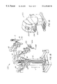
- FIG. 2A shows a side view of a robotic arm and surgical instrument assembly
- FIG. 2B shows a three-dimensional view corresponding to FIG. 2A
- FIG. 3 shows a three-dimensional view of a surgical instrument
- FIG. 4 shows a schematic kinematic diagram corresponding to the side view of the robotic arm shown in FIG. 2A, and indicates the arm having been displaced from one position into another position;
- FIG. 5 shows, at an enlarged scale, a wrist member and end effector of the surgical instrument shown in FIG. 3, the wrist member and end effector being movably mounted on a working end of a shaft of the surgical instrument;
- FIG. 6A shows a three-dimensional view of a hand held part or wrist gimbal of a master control device of the telesurgical system
- FIG. 6B shows a three-dimensional view of an articulated arm portion of the master control device of the telesurgical system on which the wrist gimbal of FIG. 6A is mounted in use;
- FIG. 6C shows a three-dimensional view of the master control device showing the wrist gimbal of FIG. 6A mounted on the articulated arm portion of FIG. 6B;
- FIG. 7 shows a schematic three-dimensional drawing indicating the positions of the end effectors relative to a viewing end of an endoscope and the corresponding positions of master control devices relative to the eyes of an operator, typically a surgeon;
- FIG. 8 shows a schematic three-dimensional drawing indicating the position and orientation of an end effector relative to a camera Cartesian coordinate reference system
- FIG. 9 shows a schematic three-dimensional drawing indicating the position and orientation of a pincher formation of the master control device relative to an eye Cartesian coordinate reference system
- FIG. 10 shows a schematic side view of part of the surgical station of the minimally invasive surgical apparatus indicating the location of Cartesian reference coordinate systems used by a control system of the minimally invasive surgical apparatus to determine the position and orientation of an end effector relative to a Cartesian reference coordinate system at the viewing end of an image capturing device;
- FIG. 11 shows a schematic side view of part of the operator station of the minimally invasive surgical apparatus indicating the location of Cartesian reference coordinate systems used by the control system of the minimally invasive surgical apparatus to determine the position and orientation of the pincher formation of the master control device relative to an eye Cartesian reference coordinate system;
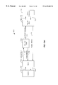
- FIG. 12 shows a schematic block diagram indicating steps followed by the control system of the minimally invasive surgical apparatus in determining end effector position and orientation relative to the Cartesian reference coordinate system at the viewing end of the image capturing device;
- FIG. 13 shows a schematic block diagram indicating steps followed by the control system of the minimally invasive surgical apparatus in determining pincher formation position and orientation relative to the eye Cartesian reference coordinate system;
- FIG. 13A shows an “overview” algorithm of a control system of a minimally invasive surgical apparatus in accordance with the invention
- FIG. 14 shows a block diagram representing control steps followed by the control system of the minimally invasive surgical apparatus in effecting control between pincher formation positional and orientational movement and end effector positional and orientation movement;
- FIG. 15 shows further detail of a “simulated domain” of the control system shown in FIG. 14;
- FIG. 16 shows one embodiment of a simulation block shown in FIG. 15
- FIG. 17 shows a relationship between L and 1/L
- FIG. 18 shows another embodiment of the simulation block shown in FIG. 15;
- FIG. 19 shows a block diagram indicating the imposition of simulated velocity and position limits
- FIG. 20 shows a preferred embodiment of the simulation block shown in FIG. 15.
- FIG. 21 shows a block diagram indicating the imposition of simulated velocity and position limits relating to orientational slave movement.
- an operator station or surgeon's console of a minimally invasive telesurgical system is generally indicated by reference numeral 200 .
- the station 200 includes a viewer 202 where an image of a surgical site is displayed in use.
- a support 204 is provided on which an operator, typically a surgeon, can rest his or her forearms while gripping two master controls (not shown in FIG. 1 A), one in each hand.
- the master controls are positioned in a space 206 inwardly beyond the support 204 .
- the surgeon When using the control station 200 , the surgeon typically sits in a chair in front of the control station 200 , positions his or her eyes in front of the viewer 202 and grips the master controls one in each hand while resting his or her forearms on the support 204 .
- a cart or surgical station of the telesurgical system is generally indicated by reference numeral 300 .
- the cart 300 is positioned close to a patient requiring surgery and is then normally caused to remain stationary until a surgical procedure to be performed has been completed.
- the cart 300 typically has wheels or castors to render it mobile.
- the station 200 is typically positioned remote from the cart 300 and can be separated from the cart 300 by a great distance, even miles away, but will typically be used within an operating room with the cart 300 .
- the cart 300 typically carries three robotic arm assemblies.
- One of the robotic arm assemblies, indicated by reference numeral 302 is arranged to hold an image capturing device 304 , e.g., an endoscope, or the like.
- Each of the two other arm assemblies 10 , 10 respectively, includes a surgical instrument 14 .
- the endoscope 304 has a viewing end 306 at a remote end of an elongate shaft thereof. It will be appreciated that the endoscope 304 has an elongate shaft to permit its viewing end 306 to be inserted through an entry port into an internal surgical site of a patient's body.
- the endoscope 304 is operatively connected to the viewer 202 to display an image captured at its viewing end 306 on the viewer 202 .
- Each robotic arm assembly 10 , 10 is normally operatively connected to one of the master controls.
- the instruments 14 of the robotic arm assemblies 10 , 10 have end effectors which are mounted on wrist members which are pivotally mounted on distal ends of elongate shafts of the instruments 14 , as is described in greater detail hereinbelow. It will be appreciated that the instruments 14 have elongate shafts to permit the end effectors to be inserted through entry ports into the internal surgical site of a patient's body. Movement of the end effectors relative to the ends of the shafts of the instruments 14 is also controlled by the master controls.
- the robotic arms 10 , 10 , 302 are mounted on a carriage 97 by means of setup joint arms 95 .
- the carriage 97 can be adjusted selectively to vary its height relative to a base 99 of the cart 300 , as indicated by arrows K.
- the setup joint arms 95 are arranged to enable the lateral positions and orientations of the arms 10 , 10 , 302 to be varied relative to a vertically extending column 93 of the cart 300 . Accordingly, the positions, orientations and heights of the arms 10 , 10 , 302 can be adjusted to facilitate passing the elongate shafts of the instruments 14 and the endoscope 304 through the entry ports to desired positions relative to the surgical site.
- the setup joint arms 95 and carriage 97 are typically locked in position.
- FIGS. 2A and 2B of the drawings one of the robotic arm assemblies 10 is shown in greater detail.
- Each assembly 10 includes an articulated robotic arm 12 , and a surgical instrument, schematically and generally indicated by reference numeral 14 , mounted thereon.
- FIG. 3 indicates the general appearance of the surgical instrument 14 in greater detail.
- the surgical instrument 14 includes an elongate shaft 14 . 1 .
- the wrist-like mechanism generally indicated by reference numeral 50 , is located at a working end of the shaft 14 . 1 .
- a housing 53 arranged releasably to couple the instrument 14 to the robotic arm 12 , is located at an opposed end of the shaft 14 . 1 .
- the shaft 14 . 1 extends along an axis indicated at 14 . 2 .
- the instrument 14 is typically releasably mounted on a carriage 11 , which can be driven to translate along a linear guide formation 24 of the arm 12 in the direction of arrows P.
- the robotic arm 12 is typically mounted on a base or platform at an end of its associated setup joint arm 95 by means of a bracket or mounting plate 16 .
- the robotic arm 12 includes a cradle, generally indicated at 18 , an upper arm portion 20 , a forearm portion 22 and the guide formation 24 .
- the cradle 18 is pivotally mounted on the plate 16 in a gimbaled fashion to permit rocking movement of the cradle 18 in the direction of arrows 26 as shown in FIG. 2B, about a pivot axis 28 .
- the upper arm portion 20 includes link members 30 , 32 and the forearm portion 22 includes link members 34 , 36 .
- the link members 30 , 32 are pivotally mounted on the cradle 18 and are pivotally connected to the link members 34 , 36 .
- the link members 34 , 36 are pivotally connected to the guide formation 24 .
- the pivotal connections between the link members 30 , 32 , 34 , 36 , the cradle 18 , and the guide formation 24 are arranged to constrain the robotic arm 12 to move in a specific manner.
- the movement of the robotic arm 12 is illustrated schematically in FIG. 4 .
- the solid lines schematically indicate one position of the robotic arm and the dashed lines indicate another possible position into which the arm can be displaced from the position indicated in solid lines.
- the pivot center 49 normally remains in the same position relative to the stationary cart 300 on which the arm 12 is mounted.
- the pivot center 49 is positioned at a port of entry into a patient's body when an internal surgical procedure is to be performed.
- the shaft 14 . 1 extends through such a port of entry, the wrist-like mechanism 50 then being positioned inside the patient's body.
- the general position of the mechanism 50 relative to the surgical site in a patient's body can be changed by movement of the arm 12 . Since the pivot center 49 is coincident with the port of entry, such movement of the arm does not excessively effect the surrounding tissue at the port of entry.
- the robotic arm 12 provides three degrees of freedom of movement to the surgical instrument 14 when mounted thereon. These degrees of freedom of movement are firstly the gimbaled motion indicated by arrows 26 , pivoting or pitching movement as indicated by arrows 27 and the linear displacement in the direction of arrows P. Movement of the arm as indicated by arrows 26 , 27 and P is controlled by appropriately positioned actuators, e.g., electrical motors, or the like, which respond to inputs from its associated master control to drive the arm 12 to a required position as dictated by movement of the master control.
- actuators e.g., electrical motors, or the like
- sensors e.g., potentiometers, encoders, or the like
- Appropriately positioned sensors are provided on the arm and its associated setup joint arm 95 to enable a control system of the minimally invasive telesurgical system to determine joint positions, as described in greater detail hereinbelow.
- sensors are referred to in this specification, the term is to be interpreted widely to include any appropriate sensors such as positional sensors, velocity sensors, or the like. It will be appreciated that by causing the robotic arm 12 selectively to displace from one position to another, the general position of the wrist-like mechanism 50 at the surgical site can be varied during the performance of a surgical procedure.
- the wrist-like mechanism 50 includes a wrist member 52 .
- One end portion of the wrist member 52 is pivotally mounted in a clevis, generally indicated at 17 , on the end 14 . 3 of the shaft 14 . 1 by means of a pivotal connection 54 .
- the wrist member 52 can pivot in the direction of arrows 56 about the pivotal connection 54 .
- An end effector, generally indicated by reference numeral 58 is pivotally mounted on an opposed end of the wrist member 52 .
- the end effector 58 is in the form of, e.g., a clip applier for anchoring clips during a surgical procedure. Accordingly, the end effector 58 has two parts 58 . 1 , 58 . 2 together defining a jaw-like arrangement.
- the end effector can be in the form of any required surgical tool, e.g., having two members or fingers which pivot relative to each other, such as scissors, pliers for use as needle drivers, or the like. Instead, it can include a single working member, e.g., a scalpel, cautery electrode, or the like.
- a tool other than a clip applier is required during the surgical procedure, the tool 14 is simply removed from its associated arm and replaced with an instrument bearing the required end effector, e.g., a scissors, or pliers, or the like.
- the end effector 58 is pivotally mounted in a clevis, generally indicated by reference numeral 19 , on an opposed end of the wrist member 52 , by means of a pivotal connection 60 .
- a pivotal connection 60 It will be appreciated that free ends 11 , 13 of the parts 58 . 1 , 58 . 2 are angularly displaceable about the pivotal connection 60 toward and away from each other as indicated by arrows 62 , 63 .
- the members 58 . 1 , 58 . 2 can be displaced angularly about the pivotal connection 60 to change the orientation of the end effector 58 as a whole, relative to the wrist member 52 .
- the end effector 58 is angularly displaceable about the pivotal connection 60 independently of the other, so that the end effector 58 , as a whole, is angularly displaceable about the pivotal connection 60 as indicated in dashed lines in FIG. 5 .
- the shaft 14 . 1 is rotatably mounted on the housing 53 for rotation as indicated by the arrows 59 .
- the end effector 58 has three degrees of freedom of movement relative to the arm 12 , namely, rotation about the axis 14 . 2 as indicated by arrows 59 , angular displacement as a whole about the pivot 60 and angular displacement about the pivot 54 as indicated by arrows 56 .
- FIG. 6C One of the master controls 700 , 700 is indicated in FIG. 6C of the drawings.
- a hand held part or wrist gimbal of the master control device 700 is indicated in FIG. 6 A and is generally indicated by reference numeral 699 .
- Part 699 has an articulated arm portion including a plurality of members or links 702 connected together by pivotal connections or joints 704 .
- the surgeon grips the part 699 by positioning his or her thumb and index finger over a pincher formation 706 .
- the surgeon's thumb and index finger are typically held on the pincher formation 706 by straps (not shown) threaded through slots 710 .
- the pincher formation 706 is squeezed between the thumb and index finger, the fingers or end effector elements of the end effector 58 close.
- the joints of the part 699 are operatively connected to actuators, e.g., electric motors, or the like, to provide for, e.g., force feedback, gravity compensation, and/or the like, as described in greater detail hereinbelow.
- actuators e.g., electric motors, or the like
- sensors e.g., encoders, or potentiometers, or the like, are positioned on each joint 704 of the part 699 , so as to enable joint positions of the part 699 to be determined by the control system.
- the part 699 is typically mounted on an articulated arm 712 as indicated in FIG. 6 B.
- Reference numeral 4 in FIGS. 6A and 6B indicates the positions at which the part 699 and the articulated arm 712 are connected together. When connected together, the part 699 can displace angularly about an axis at 4 .
- the articulated arm 712 includes a plurality of links 714 connected together at pivotal connections or joints 716 .
- the articulated arm 712 has appropriately positioned actuators, e.g., electric motors, or the like, to provide for, e.g., force feedback, gravity compensation, and/or the like.
- appropriately positioned sensors e.g., encoders, or potentiometers, or the like, are positioned on the joints 716 so as to enable joint positions of the articulated arm 712 to be determined by the control system as described in greater detail hereinbelow.
- the surgeon simply moves the pincher formation 706 to cause the end effector 58 to move to where he wants the end effector 58 to be in the image viewed in the viewer 202 .
- the end effector position and/or orientation is caused to follow that of the pincher formation 706 .
- the master control devices 700 , 700 are typically mounted on the station 200 through pivotal connections at 717 as indicated in FIG. 6 B. As mentioned hereinbefore, to manipulate each master control device 700 , the surgeon positions his or her thumb and index finger over the pincher formation 706 .
- the pincher formation 706 is positioned at a free end of the part 699 which in turn is mounted on a free end of the articulated arm portion 712 .
- the electric motors and sensors associated with the robotic arms 12 and the surgical instruments 14 mounted thereon, and the electric motors and sensors associated with the master control devices 700 are operatively linked in the control system.
- the control system typically includes at least one processor, typically a plurality of processors, for effecting control between master control device input and responsive robotic arm and surgical instrument output and for effecting control between robotic arm and surgical instrument input and responsive master control output in the case of, e.g., force feedback.
- the surgeon views the surgical site through the viewer 202 .
- the end effector 58 carried on each arm 12 is caused to perform positional and orientational movements in response to movement and action inputs on its associated master controls.
- the master controls are indicated schematically at 700 , 700 . It will be appreciated that during a surgical procedure images of the end effectors 58 are captured by the endoscope 304 together with the surgical site and are displayed on the viewer 202 so that the surgeon sees the responsive movements and actions of the end effectors 58 as he or she controls such movements and actions by means of the master control devices 700 , 700 .
- the control system is arranged to cause end effector orientational and positional movement as viewed in the image at the viewer 202 to be mapped onto orientational and positional movement of a pincher formation of the master control as will be described in greater detail hereinbelow.
- control system will be described with reference to a single master control 700 and its associated robotic arm 12 and surgical instrument 14 .
- the master control 700 will be referred to simply as “master” and its associated robotic arm 12 and surgical instrument 14 will be referred to simply as “slave.”
- control between master and slave movement is achieved by comparing master position and orientation in an eye Cartesian coordinate reference system with slave position and orientation in a camera Cartesian coordinate reference system.
- Cartesian coordinate reference system will simply be referred to as “frame” in the rest of this specification. Accordingly, when the master is stationary, the slave position and orientation within the camera frame is compared with the master position and orientation in the eye frame, and should the position and/or orientation of the slave in the camera frame not correspond with the position and/or orientation of the master in the eye frame, the slave is caused to move to a position and/or orientation in the camera frame at which its position and/or orientation in the camera frame does correspond with the position and/or orientation of the master in the eye frame.
- the camera frame is generally indicated by reference numeral 610 and the eye frame is generally indicated by reference numeral 612 in FIG. 9 .
- the new master position and/or orientation does not correspond with the previously corresponding slave position and/or orientation in the camera frame 610 .
- the control system then causes the slave to move into a new position and/or orientation in the camera frame 610 at which new position and/or orientation, its position and orientation in the camera frame 610 does correspond with the new position and/or orientation of the master in the eye frame 612 .
- control system includes at least one, and typically a plurality, of processors which compute new corresponding positions and orientations of the slave in response to master movement input commands on a continual basis determined by the processing cycle rate of the control system.
- a typical processing cycle rate of the control system under discussion is about 1300 Hz.
- the control system can have any appropriate processing cycle rate depending on the processor or processors used in the control system.
- the camera frame 610 is positioned such that its origin 614 is positioned at the viewing end 306 of the endoscope 304 .
- the z axis of the camera frame 610 extends axially along a viewing axis 616 of the endoscope 304 .
- the viewing axis 616 is shown in coaxial alignment with a shaft axis of the endoscope 304 , it is to be appreciated that the viewing axis 616 can be angled relative thereto.
- the endoscope can be in the form of an angled scope.
- the x and y axes are positioned in a plane perpendicular to the z axis.
- the endoscope is typically angularly displaceable about its shaft axis.
- the x, y and z axes are fixed relative to the viewing axis of the endoscope 304 so as to displace angularly about the shaft axis in sympathy with angular displacement of the endoscope 304 about its shaft axis.
- a frame is defined on or attached to the end effector 58 .
- This frame is referred to as an end effector frame or slave tip frame, in the rest of this specification, and is generally indicated by reference numeral 618 .
- the end effector frame 618 has its origin at the pivotal connection 60 .
- one of the axes e.g. the z axis, of the frame 618 is defined to extend along an axis of symmetry, or the like, of the end effector 58 .
- the x and y axes then extend perpendicularly to the z axis.
- the orientation of the slave is then defined by the orientation of the frame 618 having its origin at the pivotal connection 60 , relative to the camera frame 610 .
- the position of the slave is then defined by the position of the origin of the frame at 60 relative to the camera frame 610 .
- the eye frame 612 is chosen such that its origin corresponds with a position 201 where the surgeon's eyes are normally located when he or she is viewing the surgical site at the viewer 202 .
- the z axis extends along a line of sight of the surgeon, indicated by axis 620 , when viewing the surgical site through the viewer 202 .
- the x and y axes extend perpendicularly from the z axis at the origin 201 .
- the y axis is chosen to extend generally vertically relative to the viewer 202 and the x axis is chosen to extend generally horizontally relative to the viewer 202 .
- a point on the master is chosen which defines an origin of a master or master tip frame, indicated by reference numeral 622 .
- This point is chosen at a point of intersection indicated by reference numeral 3 A between axes of rotation 1 and 3 of the master, as can best be seen in FIG. 6A of the drawings.
- the z axis of the master frame 622 on the master extends along an axis of symmetry of the pincher formation 706 which extends coaxially along the rotational axis 1 .
- the x and y axes then extend perpendicularly from the axis of symmetry 1 at the origin 3 A.
- orientation of the master within the eye frame 612 is defined by the orientation of the master frame 622 relative to the eye frame 612 .
- the position of the master in the eye frame 612 is defined by the position of the origin 3 A relative to the eye frame 612 .
- FIG. 10 shows a schematic diagram of one of the robotic arm 12 and surgical instrument 14 assemblies mounted on the cart 300 .
- FIG. 10 shows a schematic diagram of one of the robotic arm 12 and surgical instrument 14 assemblies mounted on the cart 300 .
- the surgical station 300 In use, when it is desired to perform a surgical procedure by means of the minimally invasive surgical apparatus, the surgical station 300 is moved into close proximity to a patient requiring the surgical procedure.
- the patient is normally supported on a surface such as an operating table, or the like.
- the surgical station 300 is provided with the ability to have varying initial setup configurations. Accordingly, the robotic arms 12 , 12 , and the endoscope arm 302 are mounted on the carriage 97 which is heightwise adjustable, as indicated by arrows K, relative to the base 99 of the cart 300 , as can best be seen in FIGS. 1B and 10 of the drawings.
- the robotic arms 12 , 12 and the endoscope arm 302 are mounted on the carriage 97 by means of the setup joint arms 95 .
- the lateral position and orientation of the arms 12 , 12 , 302 can be selected by moving the setup joint arms 95 .
- the cart 300 is moved into the position in close proximity to the patient, an appropriate height of the carriage 97 is selected by moving it to an appropriate height relative to the base 99 and the surgical instruments 14 are moved relative to the carriage 97 so as to introduce the shafts of the instruments 14 and the endoscope 304 through the ports of entry and into positions in which the end effectors 58 and the viewing end 306 of the endoscope 304 are appropriately positioned at the surgical site and the fulcrums are coincident with the ports of entry.
- the carriage 97 is locked at its appropriate height and the setup joint arms 95 are locked in their positions and orientations. Normally, throughout the surgical procedure, the carriage 97 is maintained at the selected height and similarly the setup joint arms 95 are maintained in their selected positions. However, if required, either the endoscope or one or both of the instruments can be introduced through other ports of entry during the surgical procedure.
- the control system determines the position and orientation of the slave within the camera frame 610 by determining the position and orientation of the slave relative to a cart frame 624 and by determining the orientation and position of the endoscope 304 with reference to the same cart frame 624 .
- the cart frame 624 has an origin indicated by reference numeral 626 in FIG. 10 .
- the position of a fulcrum frame 630 having its origin at the fiulcrum 49 is determined within the cart frame 624 as indicated by the arrow 628 in dashed lines. It will be appreciated that the position of the fulcrum 49 normally remains at the same location, coincident with a port of entry into the surgical site, throughout the surgical procedure.
- the position of the end effector frame 618 on the slave, having its origin at the pivotal connection 60 is then determined relative to the fulcrum frame 630 and the orientation of the end effector frame 618 on the slave is also determined relative to the fulcrum frame 630 .
- the position and orientation of the end effector frame 618 relative to the cart frame is then determined by means of routine calculation using trigonometric relationships.
- the robotic arm 302 of the endoscope 304 is constrained to move in similar fashion to the robotic arm 10 , as indicated schematically in FIG. 4 of the drawings.
- the endoscope 304 when positioned with its viewing end 306 directed at the surgical site, also defines a fulcrum coincident with its associated port of entry into the surgical site.
- the endoscope arm 302 can be driven to cause the endoscope 304 to move into a different position during a surgical procedure, to enable the surgeon to view the surgical site from a different position in the course of performing the surgical procedure. It will be appreciated that movement of the viewing end 306 of the endoscope 304 is performed by varying the orientation of the endoscope 304 relative to its pivot center or fulcrum.
- the position and orientation of the camera frame 610 within the cart frame 624 is determined in similar fashion to the position and orientation of the slave within the cart frame 624 .
- the position and orientation of the camera frame 610 relative to the cart frame 624 and the position and orientation of the slave relative to the cart frame 624 have been determined in this manner, the position and the orientation of the slave relative to the camera frame 610 is readily determinable through routine calculation using trigonometric relationships.
- FIG. 11 shows a schematic diagram of one of the master controls 700 at the operator station 200 .
- the operator station 200 optionally also includes setup joint arms, as indicated at 632 , to enable the general location of the masters 700 , 700 to be varied to suit the surgeon.
- the general position of the masters 700 , 700 can be selectively varied to bring the masters 700 , 700 into a general position at which they are comfortably positioned for the surgeon.
- the setup joint arms 632 are locked in position and are normally maintained in that position throughout the surgical procedure.
- the surgeon's station frame 634 has its origin at a location which is normally stationary during the surgical procedure, and is indicated at 636 .
- a position of a master setup frame 640 at an end of the setup joint arms 632 on which the master 700 is mounted, relative to the station frame 636 is determined, as indicated by the arrow 638 in dashed lines.
- the position and orientation of the master frame 622 on the master 700 having its origin at 3 A is then determined relative to the master setup frame 640 .
- the position and orientation of the master frame 622 relative to the frame 634 can be determined by means of routine calculation using trigonometric relationships.
- the position and orientation of the eye frame 612 relative to the station frame 634 is determined in similar fashion.
- the position of the viewer 202 relative to the rest of the surgeon's console 200 can selectively be varied to suit the surgeon.
- the position and orientation of the master frame 622 relative to the eye frame 612 can then be determined from the position and orientation of the master frame 622 and the eye frame 612 relative to the surgeon station frame 634 by means of routine calculation using trigonometric relationships.
- control system of the minimally invasive surgical apparatus determines the position and orientation of the end effector 58 by means of the end effector frame 618 in the camera frame 610 , and, likewise, determines the position and orientation of the master by means of the master frame 622 relative to the eye frame 612 .
- the surgeon grips the master by locating his or her thumb and index finger over the pincher formation 706 .
- the point of intersection 3 A is positioned inwardly of the thumb and index finger tips.
- the master frame having its origin at 3 A is effectively mapped onto the end effector frame 618 , having its origin at the pivotal connection 60 of the end effector 58 as viewed by the surgeon in the viewer 202 .
- the frame 622 on the master 700 can be offset from the intersection 3 A so as to approach a point relative to the surgeon's hand at which point the pivotal connection 60 approximately corresponds.
- the position and orientation of the fingers of the end effector tracks orientation and position changes of the surgeon's thumb and index finger in a natural intuitive or superimposed fashion.
- actuation of the end effector 58 namely causing the end effector fingers selectively to open and close, corresponds intuitively to the opening and closing of the surgeon's thumb and index finger.
- actuation of the end effector 58 as viewed in the viewer 302 is performed by the surgeon in a natural intuitive manner, since the pivot point 60 of the end effector 58 is appropriately mapped onto a virtual pivot point between the surgeon's thumb and index finger.
- the end effector frame 618 can, where appropriate, be offset relative to the pivotal connection 60 .
- the origin of the end effector frame can be offset in a direction toward the end effector finger tips.
- the mapping of the pincher formation 706 onto the end effector 58 may be shifted, for example to map the tips of the pincher formation onto the tips of the end effector.
- the cart frame 624 can be chosen at any convenient location in which its origin corresponds with a location on the cart 300 which does not vary relative to its base 99 .
- the surgeon's station frame 634 can likewise be chosen at any convenient location such that its origin is located at a position which does not vary relative to a base 642 thereof.
- use can be made of a plurality of different intermediate frame paths.
- use can also be made of a plurality of different intermediate frame paths.
- the cart frame is chosen at 624 , as already mentioned. It will be appreciated that determining the position of the fulcrum frame 630 relative to the cart frame 624 is achieved through appropriately positioned sensors, such as potentiometers, encoders, or the like. Conveniently, the fulcrum frame position 630 relative to the cart frame 624 is determined through two intermediate frames. One of the frames is a carriage guide frame 644 which has its origin at a convenient location on a guide along which the carriage 97 is guided. The other frame, an arm platform frame indicated at 646 is positioned at an end of the setup joint arm 95 on which the robotic arm 12 is mounted.
- the carriage guide frame 644 position relative to the cart frame 624 is determined, then the platform frame 646 position relative to the carriage guide frame 644 , then the fulcrum frame 630 relative to the platform frame 646 , and then the slave orientation and position relative to the fulcrum frame 630 , thereby to determine the slave position and orientation relative to the cart frame 624 .
- the slave position and orientation relative to the cart frame 624 is determined in this manner for each arm 10 and in similar fashion for the camera frame 610 , through its arm 302 , relative to the cart frame 624 .
- the position and orientation of the master control is determined by determining the position of a base frame 648 relative to the surgeon's station frame 634 , then determining the position of the platform frame 640 relative to the base frame 648 , and then determining master position and orientation relative to the platform frame 640 .
- the position and orientation of the master frame 622 relative to the surgeon's station frame 634 is then readily determined through routine calculation using trigonometric relationships. It will be appreciated that the position and orientation of the other master frame relative to the surgeon console frame 634 is determined in a similar fashion.
- the setup joint 95 can be replaced with another setup joint while the same robotic arm is used.
- the control system can then be programmed with information, e.g., arm lengths and/or the like, relating to the new setup joint only.
- the robotic arm 10 can be replaced with another arm, the control system then requiring programming with information, e.g., fulcrum position and/or the like, relating to the new robotic arm only.
- the endoscope arm 302 and its associated setup joint can also be independently replaced, the control system then requiring programming of information relating only to the part being replaced.
- the setup joint and master control can also independently be replaced, the control system requiring programming of information relating to the characteristics of the new part only.
- FIG. 12 indicates the control steps whereby the control system of the minimally invasive surgical apparatus determines slave position and orientation, namely the position and orientation of the end effector frame 618 in the camera frame 610 .
- the position or offsets of the carriage guide frame 644 relative to the cart frame 624 is indicated at 621 .
- the offsets at 621 are fed through a forward kinematics block (FKIN) at 623 to yield corresponding Cartesian coordinates of the frame 644 relative to the cart frame 624 .
- FKIN forward kinematics block
- Sensors 625 operatively associated with the setup joint arm 95 and sensors determining the height of the carriage 97 are read by a processor 627 to determine translational and joint positions.
- the translational and joint positions are then input to an FKIN block 629 to determine corresponding Cartesian coordinates.
- the Cartesian coordinates of the carriage guide frame 644 relative to the cart frame 624 and the Cartesian coordinates of the platform frame 646 relative to the carriage frame 644 are used to determine the Cartesian coordinates of the platform frame 646 relative to the cart frame 624 .
- an offset relative to the platform frame 646 is input to an FKIN controller at 635 to yield Cartesian coordinates of the fulcrum frame 630 relative to the platform frame 646 .
- FKIN controller is to be interpreted to include an appropriate conversion matrix and kinematic relationships.
- the Cartesian coordinates of the fulcrum frame 630 relative to the cart frame 624 are determined by means of the values determined at 631 and 635 respectively.
- Cartesian coordinates of the fulcrum of the endoscope is determined relative to the cart frame 624 . This is indicated at 639 .
- the position and orientation of the endoscope 304 can be varied.
- the position and orientation of the endoscope 304 can be varied during set up of the cart 300 before the surgical procedure commences or during the performance of a surgical procedure should the surgeon wish to view the surgical site from a different location.
- sensors are provided on its associated arm 302 . These sensors, indicated at 641 , are read by a processor at 643 to determine joint positions. The joint positions thus determined are fed to an FKIN controller at 645 , together with the Cartesian coordinates determined at 639 to determine endoscope orientation and position relative to the cart frame 624 . These values are then input to 647 together with the values determined at 637 , so as to enable the fulcrum frame 630 of the slave to be determined relative to the camera frame 610 .
- the slave orientation and position is normally constantly changing. Varying joint positions and velocities are fed into an FKIN controller at 653 , together with the Cartesian coordinate values of the slave position relative to the camera frame determined at 647 to yield Cartesian position and velocity of the slave, namely the end effector frame 618 , relative to the camera frame 610 , as indicated by arrows 655 , 657 respectively.
- Cartesian position is to be interpreted to include Cartesian orientation in the rest of this specification where appropriate.
- the varying joint positions and velocities are fed into the FKIN block 653 from a simulation domain as described in greater detail hereinbelow.
- the base frame 648 normally does not change relative to the surgeon station frame 634 .
- the frame at 640 normally does not change relative to the base frame 648 .
- setup joints can optionally be provided at 632 if required.
- the position of the frame at 640 relative to the base frame 648 is assumed to be unchangeable.
- appropriate sensors would then be provided to enable the position of the frame at 640 to be determined relative to the frame at 648 .
- offsets determining the frame 648 position relative to the surgeon station frame 634 are fed through an FKIN controller 665 to yield Cartesian coordinates of the base frame 648 relative to the surgeon station frame 634 .
- offsets relating to frame 640 position relative to base frame 648 position are fed through an FKIN controller at 663 to yield Cartesian coordinates of the frame 640 relative to the base frame 648 .
- the Cartesian coordinates of the frame 640 relative to the surgeon station frame 634 are determined at 667 .
- Offsets at 697 relating to a viewer base frame, not indicated in FIG. 11, are fed through an FKIN controller at 669 to yield corresponding Cartesian coordinates of the base frame relative to the frame 634 .
- the viewer 202 can be positionally adjustable relative to the rest of the operator station 200 .
- appropriately positioned sensors 671 are provided. Sensor readings from these sensors at 671 are processed at 673 to determine joint or translational positions which are then fed through an FKIN controller at 675 to yield Cartesian coordinates of the viewer frame relative to the viewer base frame.
- the viewer frame position in Cartesian coordinates relative to the surgeon station frame 634 are determined from the values derived at 669 and 675 respectively.
- Offsets corresponding to the position of the surgeon's eyes relative to the viewer frame at 679 are fed through an FKIN controller at 681 to yield Cartesian coordinates of the position of the surgeon's eyes relative to the viewer frame.
- the values from 677 and 681 are used to determine the surgeon's eye frame 612 relative to the surgeon station frame 634 .
- the values from 667 and 683 are used to determine the position of the frame 640 relative to the eye frame 612 .
- master position and orientation relative to the eye frame 612 is continually changing during the course of a surgical procedure.
- the sensors on the master 700 are read by a processor at 689 to determine master joint position and velocity.
- These joint position and velocity values are then fed through an FKIN controller at 691 , together with the value derived at 685 to yield master Cartesian position and velocity values 693 , 695 relating to Cartesian position and velocity of master frame 622 , relative to the eye frame 612 .
- an initial position of the master 700 is set to correspond with an initial position of the slave. Thereafter, as the master 700 is moved, the control system monitors such movement and commands the slave to track the master movement.
- the frame 618 on the slave at the pivotal connection 60 relative to its reference frame 610 at the viewing end 306 of the endoscope 304 , at the initial position, is mapped onto the master frame 622 relative to its reference eye frame 612 at its initial position.
- the system maps an initial orientation of the pincher formation frame 622 with an initial orientation of the end effector frame 618 .
- the orientation of the end effector frame 618 is also caused to track the orientation of the master frame 622 .
- the position and orientation of the slave in the camera frame 610 need not correspond identically with the position and orientation of the master in the eye frame 612 . Accordingly, offsets can be introduced relating to the orientation and the position of the end effector frame 618 relative to the camera frame 610 to define an arbitrary end effector frame position and orientation which corresponds to a master frame 622 position and orientation in the eye frame 612 . It will be appreciated that the control system can readily determine the orientation and the position of the end effector frame 618 relative to the camera frame 610 at which it is to correspond with that of the master frame relative to the eye frame by means of the frames and offsets discussed above.
- control system of the minimally invasive surgical apparatus will now be described in overview fashion with reference to FIG. 13A of the drawings and individual aspects of the control system will then be described in greater detail with reference to FIGS. 9 to 21 .
- the control system of the minimally invasive surgical apparatus is generally indicated by reference numeral 810 .
- control system 810 will be described in terms of the operative association between a single master control device and its associated robotic arm and instrument assembly.
- master 700 will simply be referred to as master 700 in the rest of this specification.
- slave 798 its associated robotic arm and instrument assembly will simply be referred to as slave 798 .
- the slave 798 includes one of the robotic arm assemblies 12 having a surgical instrument 14 mounted thereon.
- Control between master 700 and slave 798 is performed by means of a simulated or virtual domain.
- the simulated domain is indicated by reference numeral 812 .
- the surgeon is schematically indicated at 701 .
- the surgeon commands responsive slave movements by selectively moving the master 700 from one position to a next position on a continual basis during the performance of a surgical procedure.
- the movement input commands on the master 700 by the surgeon 701 is indicated by arrow 703 .
- the system 810 monitors the position of the master within a reference system as already described.
- the movement input commands on the master 700 are transformed from joint space to Cartesian space and are then input to the simulated domain 812 as indicated by arrow 707 .
- responsive slave movement commands as dictated by master input commands is continually monitored at the processing cycle rate, i.e., about 1300 Hz, of the control system 810 .
- the simulated domain 812 monitors resultant slave responsive movement in a simulated environment before the actual slave 798 is instructed to respond to the master control input commands.
- the slave 798 has certain physical movement limitations or constraints. For example, the end effector 58 cannot be moved to a position, relative to the mounting plate 16 , beyond the positional range dictated by the mechanical arm and pivotal connection structures. Furthermore, it is desirable to limit to a maximum the velocity of the slave 798 when moving in response to master control input. Furthermore, the slave 798 has certain positional singularities, which will be described in greater detail hereinbelow, in which responsive movement is not readily achievable, and the closer a singularity is approached the more difficult it becomes for the slave 798 to respond effectively.
- the control system tracks the simulated responsive slave movements. Should the responsive slave movements as dictated by master input commands not transgress these limitations, corresponding commands are sent to the actual slave 798 to cause it to track master movement input commands. However, should the master input commands correspond with a responsive slave movement in the simulated domain 812 which transgresses one or more of the limitations, the corresponding slave movement commands are restricted in the simulated domain 812 to remain within the limitations. Instructions corresponding to the restricted slave movement commands are then forwarded to the actual slave ensuring that the actual slave does not transgress the limitations set in the simulated domain 812 .
- the instructions from the simulated domain 812 to the slave 798 are indicated by reference numeral 711 and are in the form of joint space commands. Where the slave movement commands have been restricted, instructions are sent to the master 700 corresponding to the degree of restriction and as indicated by arrow 705 . In this manner, corresponding haptic feedback is provided on the master 700 so that the surgeon is urged not to move the master 700 in a manner causing the corresponding slave movement to transgress the set limitations.
- the effect of the control system 810 is that where one or more limitations have been imposed on the slave commands, the actual slave 798 is prevented from transgressing the set limitations and at generally the same time the master 700 is caused to resist movement by the surgeon beyond such limitations.
- the resistance on the master 700 is typically caused by torques on the motors associated therewith. In this manner haptic feedback is supplied to the master which is felt by the surgeon as indicated by arrow 709 .
- the end effector 58 interacts with the surgical site, indicated by reference numeral 713 , as indicated by arrow 715 .
- the control system 810 also provides for actual feedback from the slave 798 to the master 700 .
- the actual slave 798 be subjected to an extraneous force, as indicated by arrow 721
- physical feedback is directly supplied to the master 700 as indicated by arrow 717 and as discussed in greater detail hereinbelow.
- an extraneous force can typically be imposed on the slave 798 when the end effector 58 contacts tissue at the surgical site 713 for example.
- control system 810 The control system, generally indicated by reference numeral 810 , will now be described in greater detail with reference to FIG. 14 of the drawings, in which like reference numerals are used to designate similar parts or aspects, unless otherwise stated.
- the master control 700 has sensors, e.g., encoders, or potentiometers, or the like, associated therewith to enable the control system 810 to determine the position of the master control 700 in joint space as it is moved from one position to a next position on a continual basis during the course of performing a surgical procedure.
- sensors e.g., encoders, or potentiometers, or the like
- signals from these positional sensors are indicated by arrow 814 .
- Positional readings measured by the sensors at 687 are read by the processor indicated at 689 (refer to FIG. 13 ).
- the master control 700 includes a plurality of joints connecting one arm member thereof to the next, sufficient positional sensors are provided on the master 700 to enable the angular position of each arm member relative to the arm member to which it is joined to be determined thereby to enable the position and orientation of the master frame 622 on the master to be determined.
- the processor 689 As the angular positions of one arm member relative to the arm member to which it is joined is read cyclically by the processor 689 in response to movements induced on the master control 700 by the surgeon, the angular positions are continuously changing. The processor at 689 reads these angular positions and computes the rate at which these angular positions are changing.
- the processor 689 reads angular positions and computes the rate of angular change, or joint velocity, on a continual basis corresponding to the system processing cycle time, i.e., 1300 Hz. Joint position and joint velocity commands thus computed at 689 are then input to the Forward Kinematics (FKIN) controller at 691 , as already described hereinabove.
- FKIN Forward Kinematics
- the positions and velocities in joint space are transformed into corresponding positions and velocities in Cartesian space, relative to the eye frame 612 (refer to FIGS. 11 and 13 ).
- the FKIN controller 691 is a processor which typically employs a Jacobian (J) matrix to accomplish this. It will be appreciated that the Jacobian matrix transforms angular positions and velocities into corresponding positions and velocities in Cartesian space by means of conventional trigonometric relationships. Thus, corresponding positions and velocities in Cartesian space, or Cartesian velocity and position commands, are computed by the FKIN controller 691 which correspond to Cartesian position and velocity changes of the master frame 622 in the eye frame 612 .
- J Jacobian
- the velocity and the position in Cartesian space is input into a Cartesian controller, indicated at 820 , and into a scale and offset converter, indicated at 822 .
- the minimally invasive surgical apparatus provides for a scale change between master control input movement and responsive slave output movement.
- a scale can be selected where, for example, a 1-inch movement of the master control 700 is transformed into a corresponding responsive 1 ⁇ 5-inch movement on the slave.
- the Cartesian position and velocity values are scaled in accordance with the scale selected to perform the surgical procedure.
- no change in scale is effected at 822 .
- offsets are taken nto account which determine the corresponding position and/or orientation of the end ffector frame 618 in the camera frame 610 relative to the position and orientation of the master frame 622 in the eye frame 612 .
- a resultant desired slave position and desired slave velocity in Cartesian space is input to a simulated or virtual domain at 812 , as indicated by arrows 811 .
- the labeling of the block 812 as a simulated or virtual domain is for identification only. Accordingly, the simulated control described hereinbelow is performed by elements outside the block 812 also.
- the simulated domain 812 will be described in greater detail hereinbelow. However, the steps imposed on the desired slave velocity and position in the virtual domain 812 will now be described broadly for ease of understanding of the description which follows.
- a current slave position and velocity is continually monitored in the virtual or simulated domain 812 .
- the desired slave position and velocity is compared with the current slave position and velocity. Should the desired slave position and/or velocity as input from 822 not cause transgression of limitations, e.g., velocity and/or position and/or singularity, and/or the like, as set in the virtual domain 812 , a similar Cartesian slave velocity and position is output from the virtual domain 812 and input into an inverse scale and offset converter as indicated at 826 .
- the similar velocity and position output in Cartesian space from the virtual domain 812 is indicated by arrows 813 and corresponds with actual commands in joint space output from the virtual domain 812 as indicated by arrows 815 as will be described in greater detail hereinbelow.
- the inverse scale and offset converter 826 which performs the scale and offset step of 822 in reverse, the reverted Cartesian position and velocity is input into the Cartesian controller at 820 .
- the original Cartesian position and velocities as output from the FKIN controller 691 is compared with the Cartesian position and velocity input from the simulated domain 812 .
- the error signal is typically used to calculate a Cartesian force.
- the Cartesian force is typically calculated, by way of example, in accordance with the following formula:
- K is a spring constant
- B is a damping constant
- ⁇ dot over (x) ⁇ is the difference between the Cartesian velocity inputs to the Cartesian controller 820
- ⁇ x is the difference between the Cartesian position inputs to the Cartesian controller 820 .
- the Cartesian force corresponds to an amount by which the desired slave position and/or velocity extends beyond the limitations imposed in the simulated domain 812 .
- the Cartesian force which could result from a velocity limitation, a positional limitation, and/or a singularity limitation, as described in greater detail below, is then converted into a corresponding torque signal by means of the master transpose kinematics controller 828 which typically includes a processor employing a Jacobian Transpose (J T ) matrix and kinematic relationships to convert the Cartesian force to a corresponding torque in joint space.
- J T Jacobian Transpose
- FIG. 15 The imposition of the limitations in the simulated domain 812 will now be described in greater detail with reference to FIG. 15 of the drawings.
- like reference numerals are used to designate similar parts or aspects, unless otherwise stated.
- the slave desired Cartesian velocity is passed from the scale and offset converter 822 through a summation junction at 832 . It will be appreciated that the slave desired Cartesian velocity is passed through the summation junction 832 sequentially at the rate of the control system processing cycle, namely 1300 Hz. At the junction 832 , an error signal is imparted on the slave desired Cartesian velocity when the desired velocity of a prior desired Cartesian velocity signal would have instructed the simulated slave to transgress one or more limitations. This will be described in greater detail hereinbelow. If the prior desired slave velocity would not have caused a transgression, no error signal would have been generated and the desired slave velocity would then pass through the summation junction 832 unchanged.
- the velocity signal passed from the summation junction 832 is referred to as Cartesian reference velocity as indicated by arrow 833 .
- the Cartesian reference velocity is fed to a simulation block 834 .
- the reference velocity is then compared with the limitations in the simulation block 834 , as will be described in greater detail hereinbelow with reference to FIGS. 16 to 21 of the drawings.
- the slave reference velocity passes through the simulation block 834 unchanged. However, a corresponding simulated slave joint velocity is computed in the simulation block 834 .
- the simulated joint velocity is integrated in the simulation block 834 to yield a corresponding simulated joint position.
- the simulated joint velocity and position is output from the simulation block 834 as indicated by arrows 835 .
- the simulated joint velocity and position is then passed through a filter at 838 .
- the filter 838 is arranged to separate tremors from the velocity and position signals. It will be appreciated that such tremors could result from inadvertent shaking of the master control which can be induced on the master control by the surgeon. Since it would be desirable to remove such tremor movements from the actual slave velocity and position signals so as to enhance slave precisional movement in response to master input, these tremors are filtered from the velocity and position signals by means of the filter 838 . After the filtering step at 838 , resultant slave joint velocity and position signals are passed to the slave as indicated by arrows 815 and as will be described in greater detail hereinbelow.
- the simulated slave joint position and/or velocity signal can be modified in any required manner at 838 .
- modifications not requiring feedback to the master can be implemented at 838 .
- the filtering step 838 is not necessarily limited to filtering tremors from the signal only.
- the frequency of the position and/or velocity signals may be modified to inhibit resonance in the slave, for example.
- the simulated joint velocity and position after passing through the simulation block 834 , is routed through an FKIN controller at 653 to compute corresponding velocities and positions in Cartesian space, as described with reference to FIG. 12 of the drawings.
- the signals are then passed to the Cartesian controller 820 as already described with reference to FIG. 14 .
- the position signal from the FKIN controller 653 is routed into a Cartesian scaled error block at 844 .
- the desired Cartesian slave position derived from the scale and offset block 822 is also routed into the Cartesian scaled error block 844 .
- the two signals are compared at 844 to compute an error signal should they not correspond. Should the two signals be equal, namely where the desired slave velocity signal was not restricted in the simulated domain 834 , no error signal is generated.
- the simulated joint velocity output would not correspond with the reference Cartesian slave velocity input to the simulation block 834 . Accordingly, after integration in the simulation block 834 , and conversion to Cartesian space by the FKIN controller 653 , the resultant corresponding Cartesian position would not correspond with the original desired Cartesian slave position input to the Cartesian scaled error block 844 . Accordingly, an error signal of a magnitude determined typically by subtraction of the resultant Cartesian position from the original desired position and multiplication with an appropriate constant, is generated by the Cartesian scaled error block 844 . This error signal is imposed on the next desired slave velocity signal at the summation junction 832 .
- the velocity signal is input to the simulation block 834 .
- limitations are imposed in a dynamic fashion in the simulation block.
- the simulated slave position does not necessarily track the master position simultaneously. This is particularly the case where a limitation has been imposed in the simulation block 834 .
- a limitation has been imposed in the simulation block 834 .
- an appropriate velocity signal change is effected at the junction 852 to effect a positional “catch up” function on the velocity signal.
- the velocity signal input to 832 would be zero, but a Cartesian reference velocity would still be input to the simulation block 834 to effect the catching up of the simulated slave position with that of the master.
- the resultant slave joint velocity and position signal is passed from the simulated domain 812 to a joint controller 848 .
- the resultant joint velocity and position signal is compared with the current joint position and velocity.
- the current joint position and velocity is derived through the sensors on the slave as indicated at 849 after having been processed at an input processor 851 to yield slave current position and velocity in joint space.
- the joint controller 848 computes the torques required on the slave motors to cause the slave to follow the resultant joint position and velocity signal taking its current joint position and velocity into account.
- the joint torques so determined are then routed to a feedback processor at 852 and to an output processor at 854 .
- the joint torques are typically computed, by way of example, by means of the following formula:
- K is a spring constant
- B is a damping constant
- ⁇ dot over ( ⁇ ) ⁇ is the difference between the joint velocity inputs to the joint controller 851
- ⁇ is the difference between the joint position inputs to the joint controller 851 .
- the output processor 854 determines the electrical currents to be supplied to the motors associated with the slave to yield the commanded torques and causes the currents to be supplied to the motors as indicated by arrow 855 .
- force feedback is supplied to the master.
- force feedback is provided on the master 700 whenever a limitation is induced in the simulated domain 812 .
- force feedback is provided directly from the slave 798 , in other words, not through a virtual or simulated domain but through direct slave movement. This will be described in greater detail hereinbelow.
- the slave indicated at 798 is provided with a plurality of sensors. These sensors are typically operatively connected to pivotal joints on the robotic arm 10 and on the instrument 14 .
- These sensors are operatively linked to the processor at 851 . It will be appreciated that these sensors determine current slave position. Should the slave 798 be subjected to an external force great enough to induce reactive movement on the slave 798 , the sensors will naturally detect such movement. Such an external force could originate from a variety of sources such as when the robotic arm 10 is accidentally knocked, or knocks into the other robotic arm 10 or the endoscope arm 302 , or the like. As mentioned, the joint controller 848 computes torques required to cause the slave 798 to follow the master 700 . An external force on the slave 798 which causes its current position to vary also causes the required slave movement to follow the master to vary.
- a compounded joint torque is generated by the joint controller 848 , which torque includes the torque required to move the slave to follow the master and the torque required to compensate for the reactive motion induced on the slave by the external force.
- the torque generated by the joint controller 848 is routed to the feedback processor at 852 , as already mentioned.
- the feedback processor 852 analyzes the torque signal from the joint controller 848 and accentuates that part of the torque signal resulting from the extraneous force on the slave 798 .
- the part of the torque signal accentuated can be chosen depending on requirements. In this case, only the part of the torque signal relating to the robotic arm 12 , 12 , 302 joints are accentuated.
- the torque signal after having been processed in this way is routed to a kinematic mapping block 860 from which a corresponding Cartesian force is determined.
- the information determining slave fulcrum position relative to the camera frame is input from 647 as indicated.
- the Cartesian force is readily determined relative to the camera frame.
- This Cartesian force is then passed through a gain step at 862 appropriately to vary the magnitude of the Cartesian force.
- the resultant force in Cartesian space is then passed to the summation junction at 827 and is then communicated to the master control 700 as described earlier.
- Reference numeral 866 generally indicates another direct force feedback path of the control system 810 , whereby direct force feedback is supplied to the master control 700 .
- the path 866 includes one or more sensors which are not necessarily operatively connected to slave joints. These sensors can typically be in the form of force or pressure sensors appropriately positioned on the surgical instrument 14 , typically on the end effector 58 . Thus, should the end effector 58 contact an extraneous body, such as body tissue at the surgical site, it generates a corresponding signal proportionate to the force of contact. This signal is processed by a processor at 868 to yield a corresponding torque. This torque is passed to a kinematic mapping block 864 , together with information from 647 to yield a corresponding Cartesian force relative to the camera frame.
- the resultant force is passed through a gain block at 870 and then forwarded to the summation junction 827 .
- Feedback is imparted on the master control 700 by means of torque supplied to the motors operatively associated with the master control 700 as described earlier. It will be appreciated that this can be achieved by means of any appropriate sensors such as current sensors, pressure sensors, accelerometers, proximity detecting sensors, or the like.
- the control system 810 enables limitations to be set in the simulation block 834 .
- These limitations can be chosen to conform with mechanical system limitations or constraints and/or can be preset to correspond with environmentally-sensitive movement limitations at the surgical site as will be described in greater detail hereinbelow.
- the limitations imposed in the simulated domain 812 in one instance, can be regarded as virtual limitations corresponding with actual physical system limitations.
- the limitations at the simulated domain 812 are not derived from actual slave movement but from simulated or virtual slave movement. Thus, the slave is prevented from actually transgressing a limitation by simulating its movement and velocity and restricting the simulated movement and velocity before instructing the actual slave to respond.
- One typical limitation set in the simulated domain 812 concerns singularities of the system.
- the instrument 14 when mounted on the robotic arm 10 is linearly displaceable in the direction of arrow P. If the instrument 14 is positioned such that the end effector 58 is relatively far removed from the fulcrum 49 and the master control is manipulated to command responsive movements, the responsive movement of the slave can normally readily be performed. At a specific fixed distance from the fulcrum 49 , the end effector has a range of lateral movement constrained within bounds dictated by constraints in the mechanical structure of the arm 12 .
- the control system 810 is arranged to provide a method of inhibiting the robotic arm from making too rapid or large a movement in response to master input because of the singularity described above.
- the end effector 58 is angularly displaceable about axis 14 . 2 as indicated by arrows 59 .
- axis of symmetry 60 A of the end effector be positioned along the axis 14 . 2
- angular displacement of the end effector about axis 60 A is readily induced.
- angular displacement of the end effector 58 about axis 60 A is not possible.
- a singularity is approached as the axis 60 A approaches a position perpendicular to the axis 14 . 2 .
- a further singularity of the robotic arm 10 can be understood with reference to FIG. 4 of the drawings.
- the robotic arm is angularly displaceable about axis 28 as indicated by arrows 26 .
- the axis 14 . 2 is perpendicular to the axis 28 , movement of the arm 10 in the direction of arrows 26 is readily induced on the end effector 58 .
- a singularity is approached the closer the axis 14 . 2 is moved toward a position parallel to the axis 28 .
- Another typical limitation imposed in the simulated domain 812 relates to positional constraints of the various joints.
- Another typical limitation imposed in the simulated domain is a velocity limitation corresponding to practicably mechanically achievable slave velocity.
- the slave has greater mass and moments of inertia than the master.
- the slave would be commanded to move in sympathy with the master but at a rate not practicably achievable by the arm 10 due to mechanical constraints.
- one embodiment of the simulation block 834 includes a modified Jacobian inverse controller indicated by J ⁇ 1* at 870 .
- the modified Jacobian inverse controller is arranged to inhibit the detrimental effects which result when a singularity is approached. This is achieved by modifying a Jacobian inverse matrix of the controller J ⁇ 1* .
- the modification to the matrix will now be described by way of example and with reference to FIGS. 2A and 17 of the drawings.
- the Jacobian matrix is typically in the form of a 6 ⁇ 6 term matrix for converting joint space coordinates to corresponding Cartesian coordinates.
- some of the terms in the matrix include a multiplication factor equal to L. Accordingly, when it is required to determine positions in joint space corresponding to Cartesian coordinates, the following relationship is used:
- the Jacobian Inverse matrix is replaced with a function of L which yields a resultant relationship between L and 1/L as indicated in dashed lines in FIG. 17 .
- Two dashed lines are indicated to show different possible functions of L.
- the Jacobian Inverse matrix is modified to cater for all the singularities of the system already described.
- the modified Jacobian Inverse controller which makes allowance for singularities as hereinbefore described is indicated by the reference numeral 870 .
- the Cartesian space reference velocity is input as indicated by arrow 833 .
- the resultant joint velocity is output at 874 .
- the resultant joint velocity 874 is then input to ajoint velocity limitation step at 876 .
- the resultant joint velocity is limited to remain within a range between a predetermined maximum velocity V max , and a predetermined minimum velocity V min .
- V max maximum velocity
- V min predetermined minimum velocity
- These maximum and minimum values are typically selected to constrain the joint velocity within limitations corresponding to constraints of the mechanical structure of the system. Accordingly, at 876 , should the joint velocity input 874 have a magnitude greater than the maximum and minimum values, the joint velocity magnitude 874 is decreased to within the set range.
- ⁇ dot over ( ⁇ ) ⁇ represents joint velocity
- max denotes a positive magnitude
- min denotes a negative magnitude
- the joint velocity is integrated at 878 to yield a corresponding position in joint space.
- the position is limited at 880 to remain within a set positional range.
- the resultant joint positional signal is routed to the filter 838 as indicated by one of the arrows 835 and as already described herein with reference to FIG. 14 .
- the resultant velocity signal as output from 876 is routed to the filter 838 as indicated by the other arrow 835 .
- the resultant velocity signal is linked to the positional control step 880 , as indicated at 881 , so that in the event that the position is limited, the velocity signal is rendered zero.
- the present method may comprise tapping the velocity signal in joint space prior to passing it through the integration step, and rendering the tapped velocity signal zero should the corresponding surgical instrument position signal in joint space transgress the positional limitation in joint space.
- Cartesian reference velocity in the simulation block 834 indicated in FIG. 14 to yield a simulated slave joint position and velocity.
- Cartesian reference velocity input to the simulation block 834 is then simply transferred into corresponding slave joint position and velocity signals without any imposition of limitations.
- the corresponding slave joint position and velocity is then forwarded to the slave after the filtering step at 838 .
- FIG. 18 of the drawings An alternative simulation block 834 B and another method of imposing limitations will now be described with reference to FIG. 18 of the drawings in which like reference numerals are used to designate similar parts unless otherwise indicated.
- the Cartesian reference velocity is initially input into a Cartesian position and velocity limit block at 902 .
- any desired limitations to position and velocity in Cartesian space can be set. This can be achieved in similar fashion to the manner in which the joint velocity and position limitations were imposed in FIG. 16 .
- Such limitations can be chosen to suit the specific surgical procedure to be performed. Thus, for example, should the surgical procedure to be performed be at a sensitive location, such as close to the brain, or heart, or the like, limitations can be set to constrain end effector movement within a space so as not to be able to contact the area of sensitivity.
- limitations can be tailored to meet specific environmental limitations defined by the specific surgical procedure to be performed so as to avoid accidental damage to a sensitive organ, or the like.
- slave position and velocity can be restricted to remain within preset limitations dictated by the surgical procedure to be performed. It will be appreciated that such surgical enviromnent dependent limitations can be imposed in the simulation block 834 in FIG. 16, and also in the preferred simulation block 834 A to be discussed with reference to FIG. 20 .
- the resultant Cartesian velocity is input to a modified Jacobian Inverse controller at 904 .
- the modified controller 904 imposes limitations on the Cartesian velocity input during conversion of the Cartesian velocity input into a corresponding joint space velocity to make allowance for singularities as already described.
- the resultant joint velocity is input into ajoint position and velocity block at 906 .
- the joint velocity input is monitored to ensure that corresponding velocity and position commands to each specific joint would not transgress set limitations corresponding to actual angular position and velocity limitations of that joint.
- the resultant simulated slave joint velocity is output as indicated by arrow 835 .
- the simulated slave joint velocity is also fed through an integration step at 910 to yield the corresponding simulated slave joint position.
- the simulated joint position for each specific joint is routed to the joint position and velocity block 906 , and the modified Jacobian Inverse block 904 as indicated in dashed lines.
- the position signal 835 is routed to the modified Jacobian Inverse block 904 to enable transformation from Cartesian to joint space.
- the position signal 835 is routed to the position and velocity block 906 in order that joint position and velocity limits can be imposed at 906 .
- FIG. 19 exemplifies the imposition of positional and velocity limits on a single joint. The same method of imposing such positional and velocity limits is employed for each joint at 906 .
- the joint velocity input from the modified Jacobian Inverse controller at 904 is indicated by arrow 912 .
- the resultant velocity after having passed through the joint position and velocity block is indicated by arrow 914 and the joint position input is indicated by arrow 835 and is shown in dashed lines.
- the joint for which position and velocity limits are to be imposed by the block diagram shown in FIG. 19 normally has physical limitations.
- the joint has a maximum position in which the arm members which are pivotally connected thereby are at a maximum angular position relative to each other.
- the joint has a minimum position in which the arm members which are connected one to another thereby are at a minimum angular position relative to each other. Accordingly, the joint has an angular displacement range extending between its minimum and its maximum position.
- the angular limits of the joint are indicated by blocks 918 and 920 , respectively, block 918 indicating the minimum position and block 920 the maximum position.
- the limits can be chosen to suit. Accordingly, the minimum and maximum angular positions 918 , 920 need not necessarily correspond with the actual physical positional limits of the joint, but can be chosen at any appropriate angular positions within the angular positional range capabilities of the joint.
- the position input at 835 is normally varying continually as the surgeon manipulates the master during the course of a surgical procedure.
- the positional input 835 is fed to the summation junctions 922 , 924 .
- the angular position as input at 835 is compared with the positional minimum or lower limit to yield an angular value corresponding to the angular deviation of the position input 835 relative to the limit 918 .
- an angular value equal to the difference between the angular limit and the angular position input 835 is determined.
- the angular deviation from the lower limit 918 thus determined, is then fed to a velocity determination block at 926 .
- the processing cycle rate of the control system is known. In this case, it is typically 1300 Hz.
- the velocity which the joint needs to have to cause its position to coincide with the lower joint limit 918 at the next processing cycle is determined. This velocity value is then routed to a decision block at 928 .
- the resultant velocity value derived at 926 will be very large, and typically physically unattainable.
- the velocity output from 926 becomes less than the attainable joint velocity and becomes zero where the angular position 835 is at the lower limit 918 .
- Reference numeral 930 represents a set joint velocity limit. This limit is typically chosen in accordance with the acceptable joint velocity limit of that joint. This set velocity lower limit is also fed into the decision block 928 . At 928 the two joint velocities are compared and the largest of the two selected. It will be appreciated that the largest value is selected because we are regarding a velocity limit in a negative direction. Thus, the largest value is the same as the smallest absolute value. The selected velocity value thus determined defines the lower velocity limit as indicated at 932 .
- a maximum velocity as indicated by reference numeral 935 is determined in similar fashion as the minimum velocity, as can be seen in FIG. 19 of the drawings.
- FIG. 20 a preferred simulation block 834 A will now be described.
- the same reference numerals are used to designate similar parts or aspects unless otherwise stated.
- the Cartesian reference velocity is input as indicated by arrow 833 .
- the simulated joint positions and velocities are output at 835 .
- the Cartesian reference velocity 833 is routed to a modified full Jacobian Inverse block at 942 and to an isolation block at 944 .
- the Cartesian reference velocity signal 833 is transformed into a corresponding joint velocity signal 946 .
- the modified full Jacobian Inverse block 942 makes allowance for singularities as already described with reference to 904 in FIG. 18 .
- the modified full Jacobian Inverse block typically includes a six by six term matrix.
- the resultant joint velocity signal is passed to an isolation block 948 .
- the terms relating to the wrist joints as indicated in FIG. 5 of the drawings, are isolated from the terms relating to the joints on the robotic arm 12 , as indicated in FIGS. 2A and 2B.
- the wrist joint velocities are forwarded to a wrist joint velocity and position limitation block at 950 .
- wrist joint velocity limits are imposed on each wrist joint in similar fashion to the method described above with reference to FIG. 19 .
- the limitations are imposed simultaneously rather than on a joint by joint basis. This will now be described with reference to FIG. 21 .
- the limits for each joint are determined in similar fashion to that described with reference to FIG. 19 . But, as indicated at 970 , the limitations are used to define a corresponding velocity limitation for the three joints together as indicated by the box 972 . Accordingly, a multidimensional joint velocity limitation, in this case a three-dimensional joint velocity limitation, is provided.
- the input joint velocity signal at 951 is compared to the multidimensional joint velocity limitation, at 970 . Should the input velocity signal 951 fall entirely inside the limitation, it is unchanged by the limitation. In such a case the output velocity signal 952 is the same as the input velocity signal 951 . However, should the input velocity signal 951 fall outside the limitation, the limitation block at 970 will select the output velocity 952 according to a criterion, which will now be described.
- a joint velocity error between the input velocity signal 951 and the selected output velocity 952 is defined as illustrated at 974 .
- the joint velocity error is transformed into a Cartesian velocity error using a Jacobian matrix at 976 .
- the Jacobian matrix at 976 describes the kinematics of the wrist joints, which includes pivots 54 , 60 and axis 14 . 2 , with reference to FIG. 5 .
- the magnitude of the Cartesian velocity error is then determined at 978 .
- the criterion for selection of the output velocity 952 by the limitation block 970 is the obedience of the multidimensional limitation and the minimization of the Cartesian velocity error magnitude.
- the output 952 from the limitation block 950 represents a combined joint velocity signal including joint velocities at the joints or pivots 54 , 60 and joint velocity about axis 14 . 2 , with reference to FIG. 5 of the drawings, after any limitations relating to velocity, position and singularities have been imposed.
- the translational Cartesian velocity terms are isolated from the Cartesian reference velocity signal 833 .
- the isolated terms correspond to the Cartesian velocity commands addressing the joints on the robotic arm 12 .
- the Cartesian reference velocity signal for the outer joints only is forwarded to an adjustment block at 954 .
- the outer joint velocity can be adapted at 954 . This will now be described in greater detail and with reference to FIG. 5 of the drawings.
- a command at the master control 700 relating to only an orientation change of the end effector 58 can result in not only responsive angular movement about pivots 54 , 60 and about axis 14 . 2 but also responsive outer joint movement. This is so because of structural dissimilarities between master and slave. Thus, for the slave to perform an orientational movement corresponding to a master orientational movement, it is sometimes required for the slave outer joints to move also.
- the resultant, possibly adapted, translational Cartesian velocity signal is then forwarded to a modified translation Jacobian Inverse block at 956 .
- the signal is converted into a corresponding joint space velocity signal.
- the modified Jacobian Inverse matrix at 956 makes allowance for the fulcrum 49 singularity and the maximum robotic arm pitch singularity as already described with reference to FIG. 4 .
- the joint space velocity signal from 956 is then passed to a limitation block at 958 .
- positional and velocity limitations are imposed on the signal in a manner similar to that already described with reference to FIG. 19 or FIG. 21 of the drawings, and for each outer joint.
- the final wrist joint velocity signal and the final outer joint velocity signal are then combined at 960 to yield the simulated joint velocity 835 .
- the simulated joint velocity 835 is integrated at 962 to yield a corresponding simulated joint position, indicated by the other of the arrows 835 .
- the simulated joint position is fed to the blocks 942 , 950 , 954 , 956 and 958 to enable the required computations.
Abstract
Description
Claims (28)
Priority Applications (3)
| Application Number | Priority Date | Filing Date | Title |
|---|---|---|---|
| US09/288,068 US6493608B1 (en) | 1999-04-07 | 1999-04-07 | Aspects of a control system of a minimally invasive surgical apparatus |
| US10/269,336 US6772053B2 (en) | 1998-12-08 | 2002-10-11 | Aspects of a control system of a minimally invasive surgical apparatus |
| US10/871,467 US20050027397A1 (en) | 1999-04-07 | 2004-06-18 | Aspects of a control system of a minimally invasive surgical apparatus |
Applications Claiming Priority (1)
| Application Number | Priority Date | Filing Date | Title |
|---|---|---|---|
| US09/288,068 US6493608B1 (en) | 1999-04-07 | 1999-04-07 | Aspects of a control system of a minimally invasive surgical apparatus |
Related Child Applications (1)
| Application Number | Title | Priority Date | Filing Date |
|---|---|---|---|
| US10/269,336 Continuation US6772053B2 (en) | 1998-12-08 | 2002-10-11 | Aspects of a control system of a minimally invasive surgical apparatus |
Publications (1)
| Publication Number | Publication Date |
|---|---|
| US6493608B1 true US6493608B1 (en) | 2002-12-10 |
Family
ID=23105611
Family Applications (3)
| Application Number | Title | Priority Date | Filing Date |
|---|---|---|---|
| US09/288,068 Expired - Lifetime US6493608B1 (en) | 1998-12-08 | 1999-04-07 | Aspects of a control system of a minimally invasive surgical apparatus |
| US10/269,336 Expired - Lifetime US6772053B2 (en) | 1998-12-08 | 2002-10-11 | Aspects of a control system of a minimally invasive surgical apparatus |
| US10/871,467 Abandoned US20050027397A1 (en) | 1999-04-07 | 2004-06-18 | Aspects of a control system of a minimally invasive surgical apparatus |
Family Applications After (2)
| Application Number | Title | Priority Date | Filing Date |
|---|---|---|---|
| US10/269,336 Expired - Lifetime US6772053B2 (en) | 1998-12-08 | 2002-10-11 | Aspects of a control system of a minimally invasive surgical apparatus |
| US10/871,467 Abandoned US20050027397A1 (en) | 1999-04-07 | 2004-06-18 | Aspects of a control system of a minimally invasive surgical apparatus |
Country Status (1)
| Country | Link |
|---|---|
| US (3) | US6493608B1 (en) |
Cited By (248)
| Publication number | Priority date | Publication date | Assignee | Title |
|---|---|---|---|---|
| US20020087049A1 (en) * | 1998-02-24 | 2002-07-04 | Brock David L. | Flexible instrument |
| US20030179308A1 (en) * | 2002-03-19 | 2003-09-25 | Lucia Zamorano | Augmented tracking using video, computed data and/or sensing technologies |
| US20040024311A1 (en) * | 2002-03-06 | 2004-02-05 | Quaid Arthur E. | System and method for haptic sculpting of physical objects |
| US20040106916A1 (en) * | 2002-03-06 | 2004-06-03 | Z-Kat, Inc. | Guidance system and method for surgical procedures with improved feedback |
| US6772053B2 (en) * | 1998-12-08 | 2004-08-03 | Visx, Incorporated | Aspects of a control system of a minimally invasive surgical apparatus |
| US20060095143A1 (en) * | 2003-03-31 | 2006-05-04 | Kabushiki Kaisha Toshiba | Manipulator and its control apparatus and method |
| US20060149147A1 (en) * | 2003-06-18 | 2006-07-06 | Yanof Jeffrey H | Remotely held needle guide for ct fluoroscopy |
| US7090683B2 (en) | 1998-02-24 | 2006-08-15 | Hansen Medical, Inc. | Flexible instrument |
| US20060258938A1 (en) * | 2005-05-16 | 2006-11-16 | Intuitive Surgical Inc. | Methods and system for performing 3-D tool tracking by fusion of sensor and/or camera derived data during minimally invasive robotic surgery |
| WO2006124390A2 (en) | 2005-05-19 | 2006-11-23 | Intuitive Surgical, Inc | Software center and highly configurable robotic systems for surgery and other uses |
| US20070021738A1 (en) * | 2005-06-06 | 2007-01-25 | Intuitive Surgical Inc. | Laparoscopic ultrasound robotic surgical system |
| WO2007045810A2 (en) * | 2005-10-19 | 2007-04-26 | The Acrobot Company Limited | A tool constraint mechanism |
| US20070144298A1 (en) * | 2005-12-27 | 2007-06-28 | Intuitive Surgical Inc. | Constraint based control in a minimally invasive surgical apparatus |
| US20070162164A1 (en) * | 2005-12-22 | 2007-07-12 | Behzad Dariush | Reconstruction, Retargetting, Tracking, And Estimation Of Pose Of Articulated Systems |
| US20070255454A1 (en) * | 2006-04-27 | 2007-11-01 | Honda Motor Co., Ltd. | Control Of Robots From Human Motion Descriptors |
| US20080004603A1 (en) * | 2006-06-29 | 2008-01-03 | Intuitive Surgical Inc. | Tool position and identification indicator displayed in a boundary area of a computer display screen |
| US20080033597A1 (en) * | 2006-05-31 | 2008-02-07 | Kraft Telerobotics, Inc. | Ambidextrous robotic master controller |
| US20080046122A1 (en) * | 2003-06-30 | 2008-02-21 | Intuitive Surgical, Inc. | Maximum torque driving of robotic surgical tools in robotic surgical systems |
| US20080163118A1 (en) * | 2006-12-29 | 2008-07-03 | Jason Wolf | Representation of file relationships |
| US20080161829A1 (en) * | 2006-12-27 | 2008-07-03 | Mako Surgical Corp. | Apparatus and method for providing an adjustable positive stop in space |
| US20090012532A1 (en) * | 2002-03-06 | 2009-01-08 | Mako Surgical Corp. | Haptic guidance system and method |
| US20090024140A1 (en) * | 2007-07-20 | 2009-01-22 | Searete Llc, A Limited Liability Corporation Of The State Of Delaware | Surgical feedback system |
| US20090036902A1 (en) * | 2006-06-06 | 2009-02-05 | Intuitive Surgical, Inc. | Interactive user interfaces for robotic minimally invasive surgical systems |
| US7492116B2 (en) | 2003-07-08 | 2009-02-17 | Board Of Regents Of The University Of Nebraska | Robot for surgical applications |
| US20090074252A1 (en) * | 2007-10-26 | 2009-03-19 | Honda Motor Co., Ltd. | Real-time self collision and obstacle avoidance |
| US20090088774A1 (en) * | 2007-09-30 | 2009-04-02 | Nitish Swarup | Apparatus and method of user interface with alternate tool mode for robotic surgical tools |
| US20090118863A1 (en) * | 2007-11-01 | 2009-05-07 | Honda Motor Co., Ltd. | Real-time self collision and obstacle avoidance using weighting matrix |
| US20090157059A1 (en) * | 2007-12-14 | 2009-06-18 | Searete Llc, A Limited Liability Corporation Of The State Of Delaware | Surgical instrument navigation system |
| US20090171372A1 (en) * | 2007-12-27 | 2009-07-02 | Intuitive Surgical, Inc. | Medical device with orientable tip for robotically directed laser cutting and biomaterial application |
| US20090175540A1 (en) * | 2007-12-21 | 2009-07-09 | Honda Motor Co., Ltd. | Controlled human pose estimation from depth image streams |
| US20090192523A1 (en) * | 2006-06-29 | 2009-07-30 | Intuitive Surgical, Inc. | Synthetic representation of a surgical instrument |
| US20090248038A1 (en) * | 2008-03-31 | 2009-10-01 | Intuitive Surgical Inc., A Delaware Corporation | Force and torque sensing in a surgical robot setup arm |
| US7632265B2 (en) | 2004-05-28 | 2009-12-15 | St. Jude Medical, Atrial Fibrillation Division, Inc. | Radio frequency ablation servo catheter and method |
| US20090326552A1 (en) * | 2008-06-27 | 2009-12-31 | Intuitive Surgical, Inc. | Medical robotic system having entry guide controller with instrument tip velocity limiting |
| US7699835B2 (en) | 2001-02-15 | 2010-04-20 | Hansen Medical, Inc. | Robotically controlled surgical instruments |
| US7713190B2 (en) | 1998-02-24 | 2010-05-11 | Hansen Medical, Inc. | Flexible instrument |
| US7727185B2 (en) | 2001-02-15 | 2010-06-01 | Hansen Medical, Inc. | Coaxial catheter system |
| US20100161045A1 (en) * | 2008-12-23 | 2010-06-24 | Sorin Biomedica Cardio S.R.L. | Expandable prosthetic valve having anchoring appendages |
| US20100161129A1 (en) * | 2008-12-23 | 2010-06-24 | Intuitive Surgical, Inc. | System and method for adjusting an image capturing device attribute using an unused degree-of-freedom of a master control device |
| US7744622B2 (en) | 1999-05-10 | 2010-06-29 | Hansen Medical, Inc. | Surgical instrument |
| US7744608B2 (en) | 2001-02-15 | 2010-06-29 | Hansen Medical, Inc. | Robotically controlled medical instrument |
| US20100168918A1 (en) * | 2008-12-31 | 2010-07-01 | Intuitive Surgical, Inc. | Obtaining force information in a minimally invasive surgical procedure |
| US20100166323A1 (en) * | 2008-12-31 | 2010-07-01 | Intuitive Surgical. Inc. | Robust sparse image matching for robotic surgery |
| US20100169815A1 (en) * | 2008-12-31 | 2010-07-01 | Intuitive Surgical, Inc. | Visual force feedback in a minimally invasive surgical procedure |
| US7758569B2 (en) | 1998-02-24 | 2010-07-20 | Hansen Medical, Inc. | Interchangeable surgical instrument |
| US7772796B2 (en) | 2003-07-08 | 2010-08-10 | Board Of Regents Of The University Of Nebraska | Robotic devices with agent delivery components and related methods |
| US7775972B2 (en) | 1998-02-24 | 2010-08-17 | Hansen Medical, Inc. | Flexible instrument |
| US7789875B2 (en) | 1998-02-24 | 2010-09-07 | Hansen Medical, Inc. | Surgical instruments |
| US20100228249A1 (en) * | 2009-03-09 | 2010-09-09 | Intuitive Surgical, Inc. | User interfaces for electrosurgical tools in robotic surgical systems |
| US20100225209A1 (en) * | 2009-03-09 | 2010-09-09 | Intuitive Surgical, Inc. | Ergonomic surgeon control console in robotic surgical systems |
| US20100228264A1 (en) * | 2009-03-09 | 2010-09-09 | David Robinson | Adaptable integrated energy control system for electrosurgical tools in robotic surgical systems |
| US20100274087A1 (en) * | 2007-06-13 | 2010-10-28 | Intuitive Surgical Operations, Inc. | Medical robotic system with coupled control modes |
| US20100317965A1 (en) * | 2009-06-16 | 2010-12-16 | Intuitive Surgical, Inc. | Virtual measurement tool for minimally invasive surgery |
| WO2010151438A1 (en) | 2009-06-23 | 2010-12-29 | Intuitive Surgical Operations, Inc. | Medical robotic system providing an auxiliary view including range of motion limitations for articulatable instruments extending out of a distal end of an entry guide |
| US20110040305A1 (en) * | 2009-08-15 | 2011-02-17 | Intuitive Surgical, Inc. | Controller assisted reconfiguration of an articulated instrument during movement into and out of an entry guide |
| US7901399B2 (en) | 1998-02-24 | 2011-03-08 | Hansen Medical, Inc. | Interchangeable surgical instrument |
| WO2011028627A2 (en) * | 2009-08-26 | 2011-03-10 | The Research Foundation Of State University Of New York | System and method for endovascular telerobotic access |
| US7927271B2 (en) | 2006-05-17 | 2011-04-19 | C.R. Bard, Inc. | Endoscope tool coupling |
| US7947050B2 (en) | 2002-09-09 | 2011-05-24 | Hansen Medical, Inc. | Surgical instrument coupling mechanism |
| US7959557B2 (en) | 2002-08-14 | 2011-06-14 | Hansen Medical, Inc. | Robotic medical instrument system |
| US7960935B2 (en) | 2003-07-08 | 2011-06-14 | The Board Of Regents Of The University Of Nebraska | Robotic devices with agent delivery components and related methods |
| US7972298B2 (en) | 2004-03-05 | 2011-07-05 | Hansen Medical, Inc. | Robotic catheter system |
| US7974674B2 (en) | 2004-05-28 | 2011-07-05 | St. Jude Medical, Atrial Fibrillation Division, Inc. | Robotic surgical system and method for surface modeling |
| US7976539B2 (en) | 2004-03-05 | 2011-07-12 | Hansen Medical, Inc. | System and method for denaturing and fixing collagenous tissue |
| US8005571B2 (en) | 2002-08-13 | 2011-08-23 | Neuroarm Surgical Ltd. | Microsurgical robot system |
| US8007511B2 (en) | 2003-06-06 | 2011-08-30 | Hansen Medical, Inc. | Surgical instrument design |
| EP2384716A2 (en) | 2007-12-26 | 2011-11-09 | Intuitive Surgical Operations, Inc. | Medical robotic system with functionality to determine and display a distance indicated by movement of a tool robotically manipulated by an operator |
| US20120029529A1 (en) * | 2010-07-30 | 2012-02-02 | Lg Electronics Inc. | Medical robotic system and method of controlling the same |
| US8109996B2 (en) | 2004-03-03 | 2012-02-07 | Sorin Biomedica Cardio, S.R.L. | Minimally-invasive cardiac-valve prosthesis |
| US8155910B2 (en) | 2005-05-27 | 2012-04-10 | St. Jude Medical, Atrial Fibrillation Divison, Inc. | Robotically controlled catheter and method of its calibration |
| US20120123441A1 (en) * | 2010-11-12 | 2012-05-17 | Intuitive Surgical Operations, Inc. | Tension control in actuation of multi-joint medical instruments |
| US8190243B2 (en) | 2007-06-08 | 2012-05-29 | Cynosure, Inc. | Thermal surgical monitoring |
| US8287522B2 (en) | 2006-05-19 | 2012-10-16 | Mako Surgical Corp. | Method and apparatus for controlling a haptic device |
| US8303576B2 (en) | 1998-02-24 | 2012-11-06 | Hansen Medical, Inc. | Interchangeable surgical instrument |
| US8333204B2 (en) | 1999-06-25 | 2012-12-18 | Hansen Medical, Inc. | Apparatus and methods for treating tissue |
| US8343171B2 (en) | 2007-07-12 | 2013-01-01 | Board Of Regents Of The University Of Nebraska | Methods and systems of actuation in robotic devices |
| US8414598B2 (en) | 1998-02-24 | 2013-04-09 | Hansen Medical, Inc. | Flexible instrument |
| US8414505B1 (en) | 2001-02-15 | 2013-04-09 | Hansen Medical, Inc. | Catheter driver system |
| WO2013071071A1 (en) | 2011-11-09 | 2013-05-16 | Intuitive Surgical Operations, Inc. | Application of force feedback on an input device to urge its operator to command an articulated instrument to a preferred pose |
| WO2013071057A1 (en) | 2011-11-11 | 2013-05-16 | Intuitive Surgical Operations, Inc. | Method and system for moving a plurality of articulated instruments in tandem back towards an entry guide |
| US8512397B2 (en) | 2009-04-27 | 2013-08-20 | Sorin Group Italia S.R.L. | Prosthetic vascular conduit |
| US20130231771A1 (en) * | 2012-03-02 | 2013-09-05 | Massachusetts Institute Of Technology | Methods and Apparatus for Handheld Tool |
| US8528565B2 (en) | 2004-05-28 | 2013-09-10 | St. Jude Medical, Atrial Fibrillation Division, Inc. | Robotic surgical system and method for automated therapy delivery |
| US8540768B2 (en) | 2005-02-10 | 2013-09-24 | Sorin Group Italia S.R.L. | Cardiac valve prosthesis |
| US20130331644A1 (en) * | 2010-12-10 | 2013-12-12 | Abhilash Pandya | Intelligent autonomous camera control for robotics with medical, military, and space applications |
| WO2014020571A1 (en) * | 2012-08-02 | 2014-02-06 | Koninklijke Philips N.V. | Controller definition of a robotic remote center of motion |
| US8679096B2 (en) | 2007-06-21 | 2014-03-25 | Board Of Regents Of The University Of Nebraska | Multifunctional operational component for robotic devices |
| US8685084B2 (en) | 2011-12-29 | 2014-04-01 | Sorin Group Italia S.R.L. | Prosthetic vascular conduit and assembly method |
| US8755864B2 (en) | 2004-05-28 | 2014-06-17 | St. Jude Medical, Atrial Fibrillation Division, Inc. | Robotic surgical system and method for diagnostic data mapping |
| US20140200733A1 (en) * | 2013-01-15 | 2014-07-17 | Kabushiki Kaisha Toshiba | Support apparatus and support method |
| US8792963B2 (en) | 2007-09-30 | 2014-07-29 | Intuitive Surgical Operations, Inc. | Methods of determining tissue distances using both kinematic robotic tool position information and image-derived position information |
| US8808369B2 (en) | 2009-10-05 | 2014-08-19 | Mayo Foundation For Medical Education And Research | Minimally invasive aortic valve replacement |
| US8830224B2 (en) | 2008-12-31 | 2014-09-09 | Intuitive Surgical Operations, Inc. | Efficient 3-D telestration for local robotic proctoring |
| US8840661B2 (en) | 2008-05-16 | 2014-09-23 | Sorin Group Italia S.R.L. | Atraumatic prosthetic heart valve prosthesis |
| US8864652B2 (en) | 2008-06-27 | 2014-10-21 | Intuitive Surgical Operations, Inc. | Medical robotic system providing computer generated auxiliary views of a camera instrument for controlling the positioning and orienting of its tip |
| US20140316431A1 (en) * | 1999-09-17 | 2014-10-23 | Intuitive Surgical Operations, Inc. | Systems and methods for using the null space to emphasize manipulator joint motion anisotropically |
| US8894633B2 (en) | 2009-12-17 | 2014-11-25 | Board Of Regents Of The University Of Nebraska | Modular and cooperative medical devices and related systems and methods |
| US8903546B2 (en) | 2009-08-15 | 2014-12-02 | Intuitive Surgical Operations, Inc. | Smooth control of an articulated instrument across areas with different work space conditions |
| US8915948B2 (en) | 2002-06-19 | 2014-12-23 | Palomar Medical Technologies, Llc | Method and apparatus for photothermal treatment of tissue at depth |
| US8918211B2 (en) | 2010-02-12 | 2014-12-23 | Intuitive Surgical Operations, Inc. | Medical robotic system providing sensory feedback indicating a difference between a commanded state and a preferred pose of an articulated instrument |
| US8944070B2 (en) | 1999-04-07 | 2015-02-03 | Intuitive Surgical Operations, Inc. | Non-force reflecting method for providing tool force information to a user of a telesurgical system |
| US8971597B2 (en) | 2005-05-16 | 2015-03-03 | Intuitive Surgical Operations, Inc. | Efficient vision and kinematic data fusion for robotic surgical instruments and other applications |
| US8968267B2 (en) | 2010-08-06 | 2015-03-03 | Board Of Regents Of The University Of Nebraska | Methods and systems for handling or delivering materials for natural orifice surgery |
| US8974440B2 (en) | 2007-08-15 | 2015-03-10 | Board Of Regents Of The University Of Nebraska | Modular and cooperative medical devices and related systems and methods |
| US20150085081A1 (en) * | 2012-05-30 | 2015-03-26 | Olympus Medical Systems Corp. | Medical three-dimensional observation apparatus |
| US9010214B2 (en) | 2012-06-22 | 2015-04-21 | Board Of Regents Of The University Of Nebraska | Local control robotic surgical devices and related methods |
| US9028536B2 (en) | 2006-08-02 | 2015-05-12 | Cynosure, Inc. | Picosecond laser apparatus and methods for its operation and use |
| US9060781B2 (en) | 2011-06-10 | 2015-06-23 | Board Of Regents Of The University Of Nebraska | Methods, systems, and devices relating to surgical end effectors |
| US9089353B2 (en) | 2011-07-11 | 2015-07-28 | Board Of Regents Of The University Of Nebraska | Robotic surgical devices, systems, and related methods |
| US9155592B2 (en) | 2009-06-16 | 2015-10-13 | Intuitive Surgical Operations, Inc. | Virtual measurement tool for minimally invasive surgery |
| US9161836B2 (en) | 2011-02-14 | 2015-10-20 | Sorin Group Italia S.R.L. | Sutureless anchoring device for cardiac valve prostheses |
| US20150346115A1 (en) * | 2014-05-30 | 2015-12-03 | Eric J. Seibel | 3d optical metrology of internal surfaces |
| US9248017B2 (en) | 2010-05-21 | 2016-02-02 | Sorin Group Italia S.R.L. | Support device for valve prostheses and corresponding kit |
| US9259289B2 (en) | 2011-05-13 | 2016-02-16 | Intuitive Surgical Operations, Inc. | Estimation of a position and orientation of a frame used in controlling movement of a tool |
| US9259280B2 (en) | 1999-09-17 | 2016-02-16 | Intuitive Surgical Operations, Inc. | Phantom degrees of freedom in joint estimation and control |
| US9272416B2 (en) | 1999-09-17 | 2016-03-01 | Intuitive Surgical Operations, Inc. | Phantom degrees of freedom for manipulating the movement of mechanical bodies |
| US9289289B2 (en) | 2011-02-14 | 2016-03-22 | Sorin Group Italia S.R.L. | Sutureless anchoring device for cardiac valve prostheses |
| US9295525B2 (en) | 1999-09-17 | 2016-03-29 | Intuitive Surgical Operations, Inc. | Phantom degrees of freedom for manipulating the movement of surgical systems |
| US9301811B2 (en) | 2012-09-17 | 2016-04-05 | Intuitive Surgical Operations, Inc. | Methods and systems for assigning input devices to teleoperated surgical instrument functions |
| WO2016077543A1 (en) * | 2014-11-13 | 2016-05-19 | Intuitive Surgical Operations, Inc. | User- interface control using master controller |
| WO2016077552A1 (en) * | 2014-11-13 | 2016-05-19 | Intuitive Surgical Operations, Inc. | Interaction between user-interface and master controller |
| US9345387B2 (en) | 2006-06-13 | 2016-05-24 | Intuitive Surgical Operations, Inc. | Preventing instrument/tissue collisions |
| US9345544B2 (en) | 1999-09-17 | 2016-05-24 | Intuitive Surgical Operations, Inc. | Systems and methods for avoiding collisions between manipulator arms using a null-space |
| US9358076B2 (en) | 2011-01-20 | 2016-06-07 | Hansen Medical, Inc. | System and method for endoluminal and translumenal therapy |
| US9387045B2 (en) | 2013-05-14 | 2016-07-12 | Intuitive Surgical Operations, Inc. | Grip force normalization for surgical instrument |
| US9408669B2 (en) | 2013-03-15 | 2016-08-09 | Hansen Medical, Inc. | Active drive mechanism with finite range of motion |
| US9457168B2 (en) | 2005-07-01 | 2016-10-04 | Hansen Medical, Inc. | Robotic catheter system and methods |
| US9469034B2 (en) | 2007-06-13 | 2016-10-18 | Intuitive Surgical Operations, Inc. | Method and system for switching modes of a robotic system |
| US9486189B2 (en) | 2010-12-02 | 2016-11-08 | Hitachi Aloka Medical, Ltd. | Assembly for use with surgery system |
| US9492235B2 (en) | 1999-09-17 | 2016-11-15 | Intuitive Surgical Operations, Inc. | Manipulator arm-to-patient collision avoidance using a null-space |
| US9498292B2 (en) | 2012-05-01 | 2016-11-22 | Board Of Regents Of The University Of Nebraska | Single site robotic device and related systems and methods |
| US9517106B2 (en) | 1999-09-17 | 2016-12-13 | Intuitive Surgical Operations, Inc. | Systems and methods for commanded reconfiguration of a surgical manipulator using the null-space |
| US9579088B2 (en) | 2007-02-20 | 2017-02-28 | Board Of Regents Of The University Of Nebraska | Methods, systems, and devices for surgical visualization and device manipulation |
| US9592096B2 (en) | 2011-11-30 | 2017-03-14 | Medtech S.A. | Robotic-assisted device for positioning a surgical instrument relative to the body of a patient |
| US20170106537A1 (en) * | 2014-03-03 | 2017-04-20 | University Of Washington | Haptic Virtual Fixture Tools |
| US9743987B2 (en) | 2013-03-14 | 2017-08-29 | Board Of Regents Of The University Of Nebraska | Methods, systems, and devices relating to robotic surgical devices, end effectors, and controllers |
| EP2470080A4 (en) * | 2009-08-26 | 2017-08-30 | Carefusion 2200, Inc. | Mechanisms for positioning and/or holding surgical instruments and performing other functions, and methods of manufacture and use thereof |
| US9750432B2 (en) | 2010-08-04 | 2017-09-05 | Medtech S.A. | Method for the automated and assisted acquisition of anatomical surfaces |
| US9770305B2 (en) | 2012-08-08 | 2017-09-26 | Board Of Regents Of The University Of Nebraska | Robotic surgical devices, systems, and related methods |
| US9780518B2 (en) | 2012-04-18 | 2017-10-03 | Cynosure, Inc. | Picosecond laser apparatus and methods for treating target tissues with same |
| US9782130B2 (en) | 2004-05-28 | 2017-10-10 | St. Jude Medical, Atrial Fibrillation Division, Inc. | Robotic surgical system |
| US9789608B2 (en) | 2006-06-29 | 2017-10-17 | Intuitive Surgical Operations, Inc. | Synthetic representation of a surgical robot |
| US9801686B2 (en) | 2003-03-06 | 2017-10-31 | Mako Surgical Corp. | Neural monitor-based dynamic haptics |
| EP3119338A4 (en) * | 2014-03-17 | 2017-11-15 | Intuitive Surgical Operations, Inc. | Automatic push-out to avoid range of motion limits |
| WO2018013212A1 (en) | 2016-07-14 | 2018-01-18 | Intuitive Surgical Operations, Inc. | Compact binocular image capture device |
| US9888966B2 (en) | 2013-03-14 | 2018-02-13 | Board Of Regents Of The University Of Nebraska | Methods, systems, and devices relating to force control surgical systems |
| US9918841B2 (en) | 2009-03-19 | 2018-03-20 | Sorin Group Italia S.R.L. | Universal valve annulus sizing device |
| WO2018071821A1 (en) | 2016-10-14 | 2018-04-19 | Intuitive Surgical Operations, Inc. | Image capture device with reduced fogging |
| US10008017B2 (en) | 2006-06-29 | 2018-06-26 | Intuitive Surgical Operations, Inc. | Rendering tool information as graphic overlays on displayed images of tools |
| EP3351203A1 (en) | 2008-06-27 | 2018-07-25 | Intuitive Surgical Operations Inc. | Medical robotic system providing an auxiliary view of articulatable instruments extending out of a distal end of an entry guide |
| WO2018145030A1 (en) | 2017-02-06 | 2018-08-09 | Intuitive Surgical Operations, Inc. | System and method for extracting multiple feeds from a rolling-shutter sensor |
| US10046140B2 (en) | 2014-04-21 | 2018-08-14 | Hansen Medical, Inc. | Devices, systems, and methods for controlling active drive systems |
| US10166061B2 (en) | 2014-03-17 | 2019-01-01 | Intuitive Surgical Operations, Inc. | Teleoperated surgical system equipment with user interface |
| US10245107B2 (en) | 2013-03-15 | 2019-04-02 | Cynosure, Inc. | Picosecond optical radiation systems and methods of use |
| US10258285B2 (en) | 2004-05-28 | 2019-04-16 | St. Jude Medical, Atrial Fibrillation Division, Inc. | Robotic surgical system and method for automated creation of ablation lesions |
| WO2019094099A1 (en) | 2017-11-10 | 2019-05-16 | Intuitive Surgical Operations, Inc. | Tension control in actuation of jointed instruments |
| US10299868B2 (en) * | 2014-03-14 | 2019-05-28 | Sony Corporation | Robot arm apparatus, robot arm control method, and program |
| US10335024B2 (en) | 2007-08-15 | 2019-07-02 | Board Of Regents Of The University Of Nebraska | Medical inflation, attachment and delivery devices and related methods |
| US10342561B2 (en) | 2014-09-12 | 2019-07-09 | Board Of Regents Of The University Of Nebraska | Quick-release end effectors and related systems and methods |
| US10363103B2 (en) | 2009-04-29 | 2019-07-30 | Auris Health, Inc. | Flexible and steerable elongate instruments with shape control and support elements |
| US10376322B2 (en) | 2014-11-11 | 2019-08-13 | Board Of Regents Of The University Of Nebraska | Robotic device with compact joint design and related systems and methods |
| US10398517B2 (en) | 2016-08-16 | 2019-09-03 | Ethicon Llc | Surgical tool positioning based on sensed parameters |
| US10434324B2 (en) | 2005-04-22 | 2019-10-08 | Cynosure, Llc | Methods and systems for laser treatment using non-uniform output beam |
| US10463439B2 (en) | 2016-08-26 | 2019-11-05 | Auris Health, Inc. | Steerable catheter with shaft load distributions |
| WO2019218157A1 (en) * | 2018-05-15 | 2019-11-21 | 深圳市亚泰光电技术有限公司 | Endoscope steering adjustment method and endoscope |
| US10507066B2 (en) | 2013-02-15 | 2019-12-17 | Intuitive Surgical Operations, Inc. | Providing information of tools by filtering image areas adjacent to or on displayed images of the tools |
| US10524867B2 (en) | 2013-03-15 | 2020-01-07 | Auris Health, Inc. | Active drive mechanism for simultaneous rotation and translation |
| US10537399B2 (en) | 2016-08-16 | 2020-01-21 | Ethicon Llc | Surgical tool positioning based on sensed parameters |
| US10556092B2 (en) | 2013-03-14 | 2020-02-11 | Auris Health, Inc. | Active drives for robotic catheter manipulators |
| CN110786932A (en) * | 2019-11-19 | 2020-02-14 | 常州脉康仪医疗机器人有限公司 | Gathering and scattering type slave arm system of minimally invasive surgery robot |
| US10582973B2 (en) | 2012-08-08 | 2020-03-10 | Virtual Incision Corporation | Robotic surgical devices, systems, and related methods |
| US10583271B2 (en) | 2012-11-28 | 2020-03-10 | Auris Health, Inc. | Method of anchoring pullwire directly articulatable region in catheter |
| US10631939B2 (en) | 2012-11-02 | 2020-04-28 | Intuitive Surgical Operations, Inc. | Systems and methods for mapping flux supply paths |
| US20200146762A1 (en) * | 2014-02-28 | 2020-05-14 | Sony Corporation | Robot arm apparatus and robot arm control method |
| RU2721462C1 (en) * | 2019-12-25 | 2020-05-19 | Ассистирующие Хирургические Технологии (Аст), Лтд | Evaluation of force on robotosurgical instrument |
| US20200163731A1 (en) * | 2017-07-13 | 2020-05-28 | Intuitive Surgical Operations, Inc. | Systems and methods for switching control between multiple instrument arms |
| US10667883B2 (en) | 2013-03-15 | 2020-06-02 | Virtual Incision Corporation | Robotic surgical devices, systems, and related methods |
| US10667720B2 (en) | 2011-07-29 | 2020-06-02 | Auris Health, Inc. | Apparatus and methods for fiber integration and registration |
| US10682191B2 (en) | 2012-06-01 | 2020-06-16 | Intuitive Surgical Operations, Inc. | Systems and methods for commanded reconfiguration of a surgical manipulator using the null-space |
| US10687903B2 (en) | 2013-03-14 | 2020-06-23 | Auris Health, Inc. | Active drive for robotic catheter manipulators |
| WO2020131692A1 (en) | 2018-12-21 | 2020-06-25 | Intuitive Surgical Operations, Inc. | Surgical instruments having mechanisms for identifying and/or deactivating stapler cartridges |
| WO2020131418A1 (en) | 2018-12-21 | 2020-06-25 | Intuitive Surgical Operations, Inc. | Actuation mechanisms for surgical instruments |
| WO2020131298A1 (en) | 2018-12-21 | 2020-06-25 | Intuitive Surgical Operations, Inc. | Surgical instruments having a reinforced staple cartridge |
| US10702347B2 (en) | 2016-08-30 | 2020-07-07 | The Regents Of The University Of California | Robotic device with compact joint design and an additional degree of freedom and related systems and methods |
| US10722319B2 (en) | 2016-12-14 | 2020-07-28 | Virtual Incision Corporation | Releasable attachment device for coupling to medical devices and related systems and methods |
| US10751136B2 (en) | 2016-05-18 | 2020-08-25 | Virtual Incision Corporation | Robotic surgical devices, systems and related methods |
| US10806538B2 (en) | 2015-08-03 | 2020-10-20 | Virtual Incision Corporation | Robotic surgical devices, systems, and related methods |
| WO2020214258A1 (en) | 2019-04-15 | 2020-10-22 | Intuitive Surgical Operations, Inc. | Staple cartridge for a surgical instrument |
| WO2020242808A1 (en) | 2019-05-31 | 2020-12-03 | Intuitive Surgical Operations, Inc. | Staple cartridge for a surgical instrument |
| US10864048B2 (en) | 2012-11-02 | 2020-12-15 | Intuitive Surgical Operations, Inc. | Flux disambiguation for teleoperated surgical systems |
| US10863945B2 (en) | 2004-05-28 | 2020-12-15 | St. Jude Medical, Atrial Fibrillation Division, Inc. | Robotic surgical system with contact sensing feature |
| US20210016445A1 (en) * | 2017-12-13 | 2021-01-21 | Verb Surgical Inc. | Control modes and processes for positioning of a robotic manipulator |
| US10966823B2 (en) | 2007-10-12 | 2021-04-06 | Sorin Group Italia S.R.L. | Expandable valve prosthesis with sealing mechanism |
| US10966700B2 (en) | 2013-07-17 | 2021-04-06 | Virtual Incision Corporation | Robotic surgical devices, systems and related methods |
| US11013564B2 (en) | 2018-01-05 | 2021-05-25 | Board Of Regents Of The University Of Nebraska | Single-arm robotic device with compact joint design and related systems and methods |
| DE202021000992U1 (en) | 2021-03-05 | 2021-06-21 | lNTUITIVE SURGICAL OPERATIONS,INC. | Electrosurgical instruments for sealing and dissection |
| US11051894B2 (en) | 2017-09-27 | 2021-07-06 | Virtual Incision Corporation | Robotic surgical devices with tracking camera technology and related systems and methods |
| DE202020004565U1 (en) | 2019-12-12 | 2021-08-05 | Intuitive Surgical Operations, Inc. | Electrosurgical instruments for sealing and dissection |
| US11173617B2 (en) | 2016-08-25 | 2021-11-16 | Board Of Regents Of The University Of Nebraska | Quick-release end effector tool interface |
| EP2326254B1 (en) * | 2008-09-12 | 2021-12-08 | Accuray, Inc. | Seven or more degrees of freedom robotic manipulator having at least one redundant joint |
| US11202676B2 (en) | 2002-03-06 | 2021-12-21 | Mako Surgical Corp. | Neural monitor-based dynamic haptics |
| US11202683B2 (en) | 2019-02-22 | 2021-12-21 | Auris Health, Inc. | Surgical platform with motorized arms for adjustable arm supports |
| US11229494B2 (en) * | 2019-10-24 | 2022-01-25 | Verb Surgical Inc. | Regulating joint space velocity of a surgical robotic arm |
| US11241559B2 (en) | 2016-08-29 | 2022-02-08 | Auris Health, Inc. | Active drive for guidewire manipulation |
| US11259870B2 (en) | 2005-06-06 | 2022-03-01 | Intuitive Surgical Operations, Inc. | Interactive user interfaces for minimally invasive telesurgical systems |
| US11284958B2 (en) | 2016-11-29 | 2022-03-29 | Virtual Incision Corporation | User controller with user presence detection and related systems and methods |
| US11357595B2 (en) | 2016-11-22 | 2022-06-14 | Board Of Regents Of The University Of Nebraska | Gross positioning device and related systems and methods |
| WO2022150215A1 (en) | 2021-01-08 | 2022-07-14 | Intuitive Surgical Operations, Inc. | Surgical stapling instruments |
| US11418000B2 (en) | 2018-02-26 | 2022-08-16 | Cynosure, Llc | Q-switched cavity dumped sub-nanosecond laser |
| US11432890B2 (en) | 2018-01-04 | 2022-09-06 | Covidien Lp | Systems and assemblies for mounting a surgical accessory to robotic surgical systems, and providing access therethrough |
| US11432891B2 (en) | 2015-06-03 | 2022-09-06 | Covidien Lp | Offset instrument drive unit |
| USD963851S1 (en) | 2020-07-10 | 2022-09-13 | Covidien Lp | Port apparatus |
| US11446099B2 (en) | 2016-06-03 | 2022-09-20 | Covidien Lp | Control arm for robotic surgical systems |
| US11464593B2 (en) | 2016-06-03 | 2022-10-11 | Covidien Lp | Passive axis system for robotic surgical systems |
| US11484372B2 (en) | 2019-02-15 | 2022-11-01 | Covidien Lp | Articulation mechanisms for surgical instruments such as for use in robotic surgical systems |
| US11504231B2 (en) | 2018-05-23 | 2022-11-22 | Corcym S.R.L. | Cardiac valve prosthesis |
| US11510747B2 (en) | 2017-05-25 | 2022-11-29 | Covidien Lp | Robotic surgical systems and drapes for covering components of robotic surgical systems |
| US11523509B2 (en) | 2016-05-26 | 2022-12-06 | Covidien Lp | Instrument drive units |
| US11517183B2 (en) | 2015-10-23 | 2022-12-06 | Covidien Lp | Surgical system for detecting gradual changes in perfusion |
| US11529203B2 (en) | 2015-09-25 | 2022-12-20 | Covidien Lp | Robotic surgical assemblies and instrument drive connectors thereof |
| US11547508B2 (en) | 2016-05-26 | 2023-01-10 | Covidien Lp | Robotic surgical assemblies |
| US11553984B2 (en) | 2016-06-03 | 2023-01-17 | Covidien Lp | Robotic surgical system with an embedded imager |
| US11553974B2 (en) | 2017-05-25 | 2023-01-17 | Covidien Lp | Systems and methods for detection of objects within a field of view of an image capture device |
| US11576739B2 (en) | 2018-07-03 | 2023-02-14 | Covidien Lp | Systems, methods, and computer-readable media for detecting image degradation during surgical procedures |
| US11576562B2 (en) | 2016-04-07 | 2023-02-14 | Titan Medical Inc. | Camera positioning method and apparatus for capturing images during a medical procedure |
| US11576733B2 (en) | 2019-02-06 | 2023-02-14 | Covidien Lp | Robotic surgical assemblies including electrosurgical instruments having articulatable wrist assemblies |
| US11586106B2 (en) | 2018-12-28 | 2023-02-21 | Titan Medical Inc. | Imaging apparatus having configurable stereoscopic perspective |
| US11583358B2 (en) | 2017-09-06 | 2023-02-21 | Covidien Lp | Boundary scaling of surgical robots |
| US11596489B2 (en) | 2015-03-10 | 2023-03-07 | Covidien Lp | Measuring health of a connector member of a robotic surgical system |
| US11612446B2 (en) | 2016-06-03 | 2023-03-28 | Covidien Lp | Systems, methods, and computer-readable program products for controlling a robotically delivered manipulator |
| US11615884B2 (en) | 2018-03-06 | 2023-03-28 | Digital Surgery Limited | Techniques for virtualized tool interaction |
| US11618171B2 (en) | 2013-12-11 | 2023-04-04 | Covidien Lp | Wrist and jaw assemblies for robotic surgical systems |
| US11622824B2 (en) | 2015-06-16 | 2023-04-11 | Covidien Lp | Robotic surgical system torque transduction sensing |
| US11628022B2 (en) | 2017-09-05 | 2023-04-18 | Covidien Lp | Collision handling algorithms for robotic surgical systems |
| US11628024B2 (en) | 2018-03-08 | 2023-04-18 | Covidien Lp | Surgical robotic systems |
| US11633243B2 (en) | 2018-10-10 | 2023-04-25 | Titan Medical Inc. | Instrument insertion system, method, and apparatus for performing medical procedures |
| US11647888B2 (en) | 2018-04-20 | 2023-05-16 | Covidien Lp | Compensation for observer movement in robotic surgical systems having stereoscopic displays |
| US11666395B2 (en) | 2015-06-23 | 2023-06-06 | Covidien Lp | Robotic surgical assemblies |
| US11690691B2 (en) | 2017-02-15 | 2023-07-04 | Covidien Lp | System and apparatus for crush prevention for medical robot applications |
| US11717361B2 (en) | 2017-05-24 | 2023-08-08 | Covidien Lp | Electrosurgical robotic system having tool presence detection |
| US11717355B2 (en) | 2019-01-29 | 2023-08-08 | Covidien Lp | Drive mechanisms for surgical instruments such as for use in robotic surgical systems |
| US11779413B2 (en) | 2015-11-19 | 2023-10-10 | Covidien Lp | Optical force sensor for robotic surgical system |
| US11839441B2 (en) | 2017-05-25 | 2023-12-12 | Covidien Lp | Robotic surgical system with automated guidance |
| US11883065B2 (en) | 2012-01-10 | 2024-01-30 | Board Of Regents Of The University Of Nebraska | Methods, systems, and devices for surgical access and insertion |
| US11903658B2 (en) | 2019-01-07 | 2024-02-20 | Virtual Incision Corporation | Robotically assisted surgical system and related devices and methods |
| US11925429B2 (en) | 2015-02-19 | 2024-03-12 | Covidien Lp | Repositioning method of input device for robotic surgical system |
| US11948226B2 (en) | 2021-05-28 | 2024-04-02 | Covidien Lp | Systems and methods for clinical workspace simulation |
| US11950867B2 (en) | 2022-11-04 | 2024-04-09 | Board Of Regents Of The University Of Nebraska | Single-arm robotic device with compact joint design and related systems and methods |
Families Citing this family (75)
| Publication number | Priority date | Publication date | Assignee | Title |
|---|---|---|---|---|
| US5762458A (en) * | 1996-02-20 | 1998-06-09 | Computer Motion, Inc. | Method and apparatus for performing minimally invasive cardiac procedures |
| US6132441A (en) | 1996-11-22 | 2000-10-17 | Computer Motion, Inc. | Rigidly-linked articulating wrist with decoupled motion transmission |
| US10188471B2 (en) | 1999-09-17 | 2019-01-29 | Intuitive Surgical Operations, Inc. | Tele-operative surgical systems and methods of control at joint limits using inverse kinematics |
| US7635390B1 (en) | 2000-01-14 | 2009-12-22 | Marctec, Llc | Joint replacement component having a modular articulating surface |
| US7708741B1 (en) | 2001-08-28 | 2010-05-04 | Marctec, Llc | Method of preparing bones for knee replacement surgery |
| JP4178186B2 (en) * | 2003-08-21 | 2008-11-12 | 国立大学法人 筑波大学 | Wearable motion assist device, control method for wearable motion assist device, and control program |
| TWI228272B (en) * | 2003-09-19 | 2005-02-21 | Tinggi Technologies Pte Ltd | Fabrication of semiconductor devices |
| US20060258932A1 (en) * | 2005-05-10 | 2006-11-16 | General Electric Company | Safe motion enabling sequence and system for a medical imaging apparatus |
| US8010235B2 (en) * | 2005-05-31 | 2011-08-30 | The Boeing Company | Approaching and compensating for machine kinematic singularities |
| US8498691B2 (en) * | 2005-12-09 | 2013-07-30 | Hansen Medical, Inc. | Robotic catheter system and methods |
| WO2007111749A2 (en) * | 2005-12-20 | 2007-10-04 | Intuitive Surgical, Inc. | Method for handling an operator command exceeding a medical device state limitation in a medical robotic system |
| ES2298051B2 (en) * | 2006-07-28 | 2009-03-16 | Universidad De Malaga | ROBOTIC SYSTEM OF MINIMALLY INVASIVE SURGERY ASSISTANCE ABLE TO POSITION A SURGICAL INSTRUMENT IN RESPONSE TO THE ORDER OF A SURGEON WITHOUT FIXING THE OPERATING TABLE OR PRIOR CALIBRATION OF THE INSERT POINT. |
| US8262553B2 (en) * | 2006-09-18 | 2012-09-11 | Novartis Ag | Ophthalmic surgical console system |
| EP1915963A1 (en) | 2006-10-25 | 2008-04-30 | The European Atomic Energy Community (EURATOM), represented by the European Commission | Force estimation for a minimally invasive robotic surgery system |
| DK2099588T3 (en) | 2006-12-19 | 2012-02-06 | Univ Deakin | Method and apparatus for haptic control |
| JP5028219B2 (en) * | 2007-10-30 | 2012-09-19 | オリンパスメディカルシステムズ株式会社 | Manipulator device and medical device system |
| JP4715863B2 (en) * | 2008-05-01 | 2011-07-06 | ソニー株式会社 | Actuator control apparatus, actuator control method, actuator, robot apparatus, and computer program |
| US8332072B1 (en) | 2008-08-22 | 2012-12-11 | Titan Medical Inc. | Robotic hand controller |
| US10532466B2 (en) * | 2008-08-22 | 2020-01-14 | Titan Medical Inc. | Robotic hand controller |
| ES2360985B2 (en) * | 2008-12-23 | 2011-11-16 | Universidad Rey Juan Carlos | VIRTUAL TRAINING SYSTEM FOR ARTHROSCOPIC SURGERY. |
| US8672837B2 (en) | 2010-06-24 | 2014-03-18 | Hansen Medical, Inc. | Methods and devices for controlling a shapeable medical device |
| US8827948B2 (en) | 2010-09-17 | 2014-09-09 | Hansen Medical, Inc. | Steerable catheters |
| KR101876386B1 (en) * | 2011-12-29 | 2018-07-11 | 삼성전자주식회사 | Medical robotic system and control method for thereof |
| WO2013140679A1 (en) * | 2012-03-21 | 2013-09-26 | 三菱電機株式会社 | Track control device |
| US11135026B2 (en) | 2012-05-11 | 2021-10-05 | Peter L. Bono | Robotic surgical system |
| US9057600B2 (en) | 2013-03-13 | 2015-06-16 | Hansen Medical, Inc. | Reducing incremental measurement sensor error |
| US9271663B2 (en) | 2013-03-15 | 2016-03-01 | Hansen Medical, Inc. | Flexible instrument localization from both remote and elongation sensors |
| US9014851B2 (en) | 2013-03-15 | 2015-04-21 | Hansen Medical, Inc. | Systems and methods for tracking robotically controlled medical instruments |
| US9629595B2 (en) | 2013-03-15 | 2017-04-25 | Hansen Medical, Inc. | Systems and methods for localizing, tracking and/or controlling medical instruments |
| US11020016B2 (en) | 2013-05-30 | 2021-06-01 | Auris Health, Inc. | System and method for displaying anatomy and devices on a movable display |
| US9186795B1 (en) * | 2013-06-24 | 2015-11-17 | Redwood Robotics, Inc. | Programming and execution of force-based tasks with torque-controlled robot arms |
| JP2015016181A (en) * | 2013-07-12 | 2015-01-29 | オリンパス株式会社 | Surgery support robot |
| EP3119319B1 (en) * | 2014-03-17 | 2020-07-15 | Intuitive Surgical Operations, Inc. | Tele-operative surgical systems and methods of control at joint limits using inverse kinematics |
| US10751135B2 (en) * | 2015-03-17 | 2020-08-25 | Intuitive Surgical Operations, Inc. | System and method for providing feedback during manual joint positioning |
| KR20230054760A (en) | 2015-06-09 | 2023-04-25 | 인튜어티브 서지컬 오퍼레이션즈 인코포레이티드 | Configuring surgical system with surgical procedures atlas |
| JP6824967B2 (en) | 2015-09-18 | 2021-02-03 | オーリス ヘルス インコーポレイテッド | Tubular net navigation |
| CN108472084B (en) | 2015-11-12 | 2021-08-27 | 直观外科手术操作公司 | Surgical system with training or assisting function |
| US10143526B2 (en) | 2015-11-30 | 2018-12-04 | Auris Health, Inc. | Robot-assisted driving systems and methods |
| CN108697481B (en) * | 2016-03-04 | 2021-09-21 | 柯惠Lp公司 | Inverse kinematics control system for robotic surgical system |
| US10065311B1 (en) * | 2016-06-08 | 2018-09-04 | X Development Llc | Singularity handling for robot jogging |
| US10244926B2 (en) | 2016-12-28 | 2019-04-02 | Auris Health, Inc. | Detecting endolumenal buckling of flexible instruments |
| WO2018183727A1 (en) | 2017-03-31 | 2018-10-04 | Auris Health, Inc. | Robotic systems for navigation of luminal networks that compensate for physiological noise |
| WO2018189853A1 (en) | 2017-04-13 | 2018-10-18 | オリンパス株式会社 | Stereoscopic endoscope optical system and endoscope provided therewith |
| WO2018211595A1 (en) | 2017-05-16 | 2018-11-22 | オリンパス株式会社 | Optical system for stereoscopic viewing and imaging device equipped with same |
| US10022192B1 (en) | 2017-06-23 | 2018-07-17 | Auris Health, Inc. | Automatically-initialized robotic systems for navigation of luminal networks |
| US11395703B2 (en) | 2017-06-28 | 2022-07-26 | Auris Health, Inc. | Electromagnetic distortion detection |
| JP7317723B2 (en) | 2017-06-28 | 2023-07-31 | オーリス ヘルス インコーポレイテッド | Electromagnetic field distortion detection |
| WO2019008618A1 (en) | 2017-07-03 | 2019-01-10 | オリンパス株式会社 | Stereoscopic optical system and imaging device provided therewith |
| CN107374736B (en) * | 2017-07-31 | 2021-09-07 | 成都博恩思医学机器人有限公司 | Operation trolley |
| WO2019064515A1 (en) | 2017-09-29 | 2019-04-04 | オリンパス株式会社 | Stereoscopic optical system and imaging device equipped with same |
| US10555778B2 (en) | 2017-10-13 | 2020-02-11 | Auris Health, Inc. | Image-based branch detection and mapping for navigation |
| US11058493B2 (en) | 2017-10-13 | 2021-07-13 | Auris Health, Inc. | Robotic system configured for navigation path tracing |
| CA3080151A1 (en) | 2017-10-23 | 2019-05-02 | Peter L. BONO | Rotary oscillating/reciprocating surgical tool |
| JP7322026B2 (en) | 2017-12-14 | 2023-08-07 | オーリス ヘルス インコーポレイテッド | System and method for instrument localization |
| WO2019125964A1 (en) | 2017-12-18 | 2019-06-27 | Auris Health, Inc. | Methods and systems for instrument tracking and navigation within luminal networks |
| AU2019207913A1 (en) | 2018-01-12 | 2020-09-03 | Capstone Surgical Technologies, Llc | Robotic surgical control system |
| US10827913B2 (en) | 2018-03-28 | 2020-11-10 | Auris Health, Inc. | Systems and methods for displaying estimated location of instrument |
| CN110891469B (en) | 2018-03-28 | 2023-01-13 | 奥瑞斯健康公司 | System and method for registration of positioning sensors |
| CN114601559A (en) | 2018-05-30 | 2022-06-10 | 奥瑞斯健康公司 | System and medium for location sensor based branch prediction |
| EP3801189A4 (en) | 2018-05-31 | 2022-02-23 | Auris Health, Inc. | Path-based navigation of tubular networks |
| MX2020012904A (en) | 2018-05-31 | 2021-02-26 | Auris Health Inc | Image-based airway analysis and mapping. |
| CN112236083A (en) | 2018-05-31 | 2021-01-15 | 奥瑞斯健康公司 | Robotic system and method for navigating a luminal network detecting physiological noise |
| EP3876860A1 (en) | 2018-11-06 | 2021-09-15 | Bono, Peter L. | Robotic surgical system and method |
| US10687910B1 (en) * | 2018-12-18 | 2020-06-23 | Metal Industries Research & Development Centre | Orthopedic surgery assistant system and end effector |
| WO2021038495A1 (en) | 2019-08-30 | 2021-03-04 | Auris Health, Inc. | Instrument image reliability systems and methods |
| JP2022546421A (en) | 2019-08-30 | 2022-11-04 | オーリス ヘルス インコーポレイテッド | Systems and methods for weight-based registration of position sensors |
| KR20220056220A (en) | 2019-09-03 | 2022-05-04 | 아우리스 헬스, 인코포레이티드 | Electromagnetic Distortion Detection and Compensation |
| GB2588629B (en) * | 2019-10-29 | 2024-01-03 | Cmr Surgical Ltd | Robotic joint control |
| EP4084721A4 (en) | 2019-12-31 | 2024-01-03 | Auris Health Inc | Anatomical feature identification and targeting |
| CN114929148A (en) | 2019-12-31 | 2022-08-19 | 奥瑞斯健康公司 | Alignment interface for percutaneous access |
| EP4084720A4 (en) | 2019-12-31 | 2024-01-17 | Auris Health Inc | Alignment techniques for percutaneous access |
| CN111281649B (en) * | 2020-03-03 | 2021-08-13 | 西安交通大学 | Ophthalmic surgery robot system and control method thereof |
| CN112057172B (en) * | 2020-09-10 | 2022-02-11 | 苏州大学 | Minimally invasive surgery robot |
| CN113334358A (en) * | 2021-06-18 | 2021-09-03 | 常州机电职业技术学院 | Mechanical arm convenient to adjust and using method |
| GB2621584A (en) * | 2022-08-15 | 2024-02-21 | Cmr Surgical Ltd | Alarm system for a surgical robot |
Citations (28)
| Publication number | Priority date | Publication date | Assignee | Title |
|---|---|---|---|---|
| US4594671A (en) * | 1982-02-19 | 1986-06-10 | Hitachi, Ltd. | Velocity method of controlling industrial robot actuators |
| US4623971A (en) * | 1983-06-30 | 1986-11-18 | Cincinnati Milacron Inc. | Machine control with motor velocity constraint |
| US4716350A (en) * | 1986-12-08 | 1987-12-29 | Ford Motor Company | Method to avoid singularity in a robot mechanism |
| US4734866A (en) * | 1984-07-05 | 1988-03-29 | Siemens Aktiengesellschaft | Computer controller for an industrial multiaxis robot |
| US4942538A (en) * | 1988-01-05 | 1990-07-17 | Spar Aerospace Limited | Telerobotic tracker |
| US5072361A (en) * | 1990-02-01 | 1991-12-10 | Sarcos Group | Force-reflective teleoperation control system |
| US5159249A (en) * | 1989-05-16 | 1992-10-27 | Dalila Megherbi | Method and apparatus for controlling robot motion at and near singularities and for robot mechanical design |
| US5187796A (en) | 1988-03-29 | 1993-02-16 | Computer Motion, Inc. | Three-dimensional vector co-processor having I, J, and K register files and I, J, and K execution units |
| US5206930A (en) * | 1988-03-15 | 1993-04-27 | International Business Machines Corporation | Method of compliance control of a manipulator |
| US5299288A (en) * | 1990-05-11 | 1994-03-29 | International Business Machines Corporation | Image-directed robotic system for precise robotic surgery including redundant consistency checking |
| US5343385A (en) | 1993-08-17 | 1994-08-30 | International Business Machines Corporation | Interference-free insertion of a solid body into a cavity |
| WO1996009587A1 (en) | 1994-09-22 | 1996-03-28 | Computer Motion, Inc. | A speech interface for an automated endoscopic system |
| US5590034A (en) * | 1994-02-21 | 1996-12-31 | Asea Brown Boveri Ab | Method for controlling the movement of an industrial robot at and near singularities |
| US5625576A (en) * | 1993-10-01 | 1997-04-29 | Massachusetts Institute Of Technology | Force reflecting haptic interface |
| WO1997029690A1 (en) | 1996-02-20 | 1997-08-21 | Computer Motion, Inc. | A method and apparatus for performing minimally invasive cardiac procedures |
| WO1997043943A1 (en) | 1996-05-20 | 1997-11-27 | Intuitive Surgical, Inc. | Force-reflecting surgical instrument and positioning mechanism for performing minimally invasive surgery with enhanced dexterity and sensitivity |
| WO1997043942A1 (en) | 1996-05-20 | 1997-11-27 | Intuitive Surgical, Inc. | Articulated surgical instrument for performing minimally invasive surgery with enhanced dexterity and sensitivity |
| US5695500A (en) | 1991-06-13 | 1997-12-09 | International Business Machines Corporation | System for manipulating movement of a surgical instrument with computer controlled brake |
| WO1997049340A1 (en) | 1996-06-24 | 1997-12-31 | Computer Motion, Inc. | Multi-functional surgical control system and switching interface |
| US5749362A (en) | 1992-05-27 | 1998-05-12 | International Business Machines Corporation | Method of creating an image of an anatomical feature where the feature is within a patient's body |
| US5762458A (en) | 1996-02-20 | 1998-06-09 | Computer Motion, Inc. | Method and apparatus for performing minimally invasive cardiac procedures |
| US5841950A (en) | 1992-08-10 | 1998-11-24 | Computer Motion, Inc. | Automated endoscope system for optimal positioning |
| US5876325A (en) * | 1993-11-02 | 1999-03-02 | Olympus Optical Co., Ltd. | Surgical manipulation system |
| US5878193A (en) * | 1992-08-10 | 1999-03-02 | Computer Motion, Inc. | Automated endoscope system for optimal positioning |
| US5923139A (en) * | 1996-02-23 | 1999-07-13 | Northwestern University | Passive robotic constraint devices using non-holonomic transmission elements |
| US6219589B1 (en) * | 1997-10-22 | 2001-04-17 | Simon Fraser University | Remote manipulator with force feedback and control |
| US6233504B1 (en) * | 1998-04-16 | 2001-05-15 | California Institute Of Technology | Tool actuation and force feedback on robot-assisted microsurgery system |
| US20010016804A1 (en) * | 1996-09-04 | 2001-08-23 | Cunningham Richard L. | Surgical simulation interface device and method |
Family Cites Families (88)
| Publication number | Priority date | Publication date | Assignee | Title |
|---|---|---|---|---|
| US1418184A (en) | 1920-08-12 | 1922-05-30 | Trunick Charles | Screw driver |
| US2815697A (en) | 1950-06-06 | 1957-12-10 | Saunders-Singer Arthur Edward | Microscope manipulators or dissection manipulators |
| US2901258A (en) | 1957-09-30 | 1959-08-25 | Brandafi Gabriel | Drill press spindle |
| US3145333A (en) | 1962-10-29 | 1964-08-18 | Pardini John Anthony | Force limiting device for motor control |
| US3463329A (en) | 1967-05-18 | 1969-08-26 | Sylvania Electric Prod | Material transfer device with parallel link frame |
| CH482439A (en) | 1968-02-20 | 1969-12-15 | Contraves Ag | Observation device |
| US3818125A (en) | 1971-10-26 | 1974-06-18 | J Butterfield | Stereo television microscope |
| US3923166A (en) | 1973-10-11 | 1975-12-02 | Nasa | Remote manipulator system |
| US3921445A (en) | 1973-10-15 | 1975-11-25 | Stanford Research Inst | Force and torque sensing method and means for manipulators and the like |
| US3934201A (en) | 1974-03-22 | 1976-01-20 | Majefski Richard L | Low power consumption stereo transmitter and receiver system |
| JPS52155765A (en) | 1976-06-18 | 1977-12-24 | Yachiyo Kougiyou Kenkiyuushiyo | Industrial robot |
| US5133727A (en) | 1990-05-10 | 1992-07-28 | Symbiosis Corporation | Radial jaw biopsy forceps |
| DE2819976C2 (en) | 1978-05-08 | 1984-03-08 | Fritz 5882 Meinerzhagen Sträter | Articulated arm with wrapped parallelogram function |
| JPS594266B2 (en) | 1978-07-28 | 1984-01-28 | 元田電子工業株式会社 | Advanced control robot |
| GB2040134A (en) | 1978-11-09 | 1980-08-20 | Marconi Co Ltd | Stereoscopic television systems |
| US4264266A (en) | 1979-04-20 | 1981-04-28 | Tl Systems Corporation | Manipulator apparatus |
| US4349837A (en) | 1979-07-03 | 1982-09-14 | Spar Aerospace Limited | Satellite servicing |
| FR2460762A1 (en) | 1979-07-12 | 1981-01-30 | Technigaz | Tool orienting control system - effects positioning by deforming articulated parallelogram on carriage supporting tool |
| US4562463A (en) | 1981-05-15 | 1985-12-31 | Stereographics Corp. | Stereoscopic television system with field storage for sequential display of right and left images |
| US4419041A (en) | 1981-06-26 | 1983-12-06 | Rose Stanley E | Spacial mechanism and method |
| FR2512570A1 (en) | 1981-09-09 | 1983-03-11 | Commissariat Energie Atomique | POST-EFFORT RETURN POSITIONING SYSTEM WITH DELAY IN TRANSMISSION AND ITS APPLICATION TO A TELEMANIPULATOR |
| US4636138A (en) | 1982-02-05 | 1987-01-13 | American Robot Corporation | Industrial robot |
| DE3211688C2 (en) | 1982-03-30 | 1986-10-09 | Binder, Karl-Franz, 8077 Reichertshofen | Industrial robots for manufacturing and / or assembly purposes |
| JPS58177287A (en) * | 1982-04-05 | 1983-10-17 | 株式会社日立製作所 | Control system of robot |
| US4582067A (en) | 1983-02-14 | 1986-04-15 | Washington Research Foundation | Method for endoscopic blood flow detection by the use of ultrasonic energy |
| US4651201A (en) | 1984-06-01 | 1987-03-17 | Arnold Schoolman | Stereoscopic endoscope arrangement |
| US4583117A (en) | 1984-07-17 | 1986-04-15 | Stereographics Corporation | Stereoscopic video camera |
| DE3447769A1 (en) | 1984-12-28 | 1986-07-10 | Medicon eG, Chirurgiemechaniker-Genossenschaft, 7200 Tuttlingen | HANDLE FOR SURGICAL PURPOSES |
| JPS6233801U (en) | 1985-08-14 | 1987-02-27 | ||
| JPH085018B2 (en) | 1986-02-26 | 1996-01-24 | 株式会社日立製作所 | Remote manipulation method and apparatus |
| EP0239409A1 (en) | 1986-03-28 | 1987-09-30 | Life Technology Research Foundation | Robot for surgical operation |
| US5078140A (en) | 1986-05-08 | 1992-01-07 | Kwoh Yik S | Imaging device - aided robotic stereotaxis system |
| US4744363A (en) | 1986-07-07 | 1988-05-17 | Hasson Harrith M | Intra-abdominal organ stabilizer, retractor and tissue manipulator |
| US4873572A (en) | 1987-02-27 | 1989-10-10 | Olympus Optical Co., Ltd. | Electronic endoscope apparatus |
| JPS63278674A (en) | 1987-05-11 | 1988-11-16 | Shinko Electric Co Ltd | Offset mechanism for rotating center |
| JPS63294509A (en) | 1987-05-27 | 1988-12-01 | Olympus Optical Co Ltd | Stereoscopic endoscope device |
| US4762455A (en) | 1987-06-01 | 1988-08-09 | Remote Technology Corporation | Remote manipulator |
| US4808898A (en) | 1987-09-30 | 1989-02-28 | Keith Pearson | Gripper assembly for robot arm |
| FR2620961B1 (en) | 1987-09-30 | 1990-01-19 | Euritech | TELESCOPIC HANDLING ARM |
| DE3741632A1 (en) | 1987-12-05 | 1989-06-22 | Noell Gmbh | METHOD AND DEVICE FOR DETECTING AND CONTROLLING A SPACE TARGET |
| DE3742053C1 (en) | 1987-12-11 | 1989-03-16 | Wolf Gmbh Richard | Holder for medical instruments |
| CA1331032C (en) | 1988-01-25 | 1994-07-26 | Thony, Franz | Apparatus for detachably connecting two parts |
| US4855822A (en) | 1988-01-26 | 1989-08-08 | Honeywell, Inc. | Human engineered remote driving system |
| US4979949A (en) | 1988-04-26 | 1990-12-25 | The Board Of Regents Of The University Of Washington | Robot-aided system for surgery |
| JPH01316184A (en) | 1988-06-14 | 1989-12-21 | Mitsubishi Electric Corp | Industrial robot |
| GB8817672D0 (en) | 1988-07-25 | 1988-09-01 | Sira Ltd | Optical apparatus |
| US5002418A (en) | 1988-12-09 | 1991-03-26 | Vsi Corporation | Hold down device with extended capture pawl mechanism |
| US4942539A (en) | 1988-12-21 | 1990-07-17 | Gmf Robotics Corporation | Method and system for automatically determining the position and orientation of an object in 3-D space |
| US4922338A (en) | 1989-03-02 | 1990-05-01 | Arpino Ronald G | Line-of-sight inspection system |
| US5020933A (en) | 1989-09-01 | 1991-06-04 | Andronic Devices, Ltd. | Locking mechanism for medical devices |
| US5257998A (en) | 1989-09-20 | 1993-11-02 | Mitaka Kohki Co., Ltd. | Medical three-dimensional locating apparatus |
| US5273039A (en) | 1989-10-16 | 1993-12-28 | Olympus Optical Co., Ltd. | Surgical microscope apparatus having a function to display coordinates of observation point |
| DE69026196T2 (en) | 1989-11-08 | 1996-09-05 | George S Allen | Mechanical arm for an interactive, image-controlled, surgical system |
| US5260319A (en) | 1989-12-26 | 1993-11-09 | Hoechst-Roussel Pharmaceuticals Incorporated | Thienobenzoxepins and naphthothiophenes |
| US5060532A (en) | 1990-08-23 | 1991-10-29 | Barker Sidney L | Universal joint boom |
| JP2642776B2 (en) | 1990-09-10 | 1997-08-20 | 三田工業株式会社 | Information recording medium and information recording method |
| FR2668359B1 (en) | 1990-10-24 | 1998-02-20 | Gen Electric Cgr | MAMMOGRAPH PROVIDED WITH A PERFECTED NEEDLE HOLDER. |
| US5209747A (en) | 1990-12-13 | 1993-05-11 | Knoepfler Dennis J | Adjustable angle medical forceps |
| GB9028185D0 (en) | 1990-12-29 | 1991-02-13 | Well Equip Ltd | A release mechanism |
| US5217453A (en) | 1991-03-18 | 1993-06-08 | Wilk Peter J | Automated surgical system and apparatus |
| US5339799A (en) | 1991-04-23 | 1994-08-23 | Olympus Optical Co., Ltd. | Medical system for reproducing a state of contact of the treatment section in the operation unit |
| US5188610A (en) | 1991-10-18 | 1993-02-23 | Vetrisystems, Inc. | Fluid dispensing apparatus |
| US5281220A (en) | 1992-01-13 | 1994-01-25 | Blake Joseph W Iii | Endoscopic instrument |
| US5631973A (en) * | 1994-05-05 | 1997-05-20 | Sri International | Method for telemanipulation with telepresence |
| US5284130A (en) | 1992-06-03 | 1994-02-08 | Ratliff Jack L | Surgical instrument positioning and securing apparatus |
| US5754741A (en) * | 1992-08-10 | 1998-05-19 | Computer Motion, Inc. | Automated endoscope for optimal positioning |
| US5397323A (en) | 1992-10-30 | 1995-03-14 | International Business Machines Corporation | Remote center-of-motion robot for surgery |
| US5629594A (en) * | 1992-12-02 | 1997-05-13 | Cybernet Systems Corporation | Force feedback system |
| CA2102855A1 (en) | 1992-12-29 | 1994-06-30 | Albon E. Gilbert | Jumper cable selection and routing system |
| JP2648274B2 (en) | 1993-01-28 | 1997-08-27 | 三鷹光器株式会社 | Medical position detection device |
| US5442505A (en) * | 1993-03-01 | 1995-08-15 | Seagate Technology, Inc. | Block assembly for a disk drive with augmenting magnets |
| US5499320A (en) * | 1993-03-24 | 1996-03-12 | The United States Of America As Represented By The Administrator Of The National Aeronautics And Space Administration | Extended task space control for robotic manipulators |
| US5325866A (en) | 1993-04-20 | 1994-07-05 | Jacek Krzyzanowski | Flexible biopsy forceps |
| US5474566A (en) | 1994-05-05 | 1995-12-12 | United States Surgical Corporation | Self-contained powered surgical apparatus |
| US5480409A (en) | 1994-05-10 | 1996-01-02 | Riza; Erol D. | Laparoscopic surgical instrument |
| US5691898A (en) * | 1995-09-27 | 1997-11-25 | Immersion Human Interface Corp. | Safe and low cost computer peripherals with force feedback for consumer applications |
| US6300936B1 (en) * | 1997-11-14 | 2001-10-09 | Immersion Corporation | Force feedback system including multi-tasking graphical host environment and interface device |
| US6084587A (en) * | 1996-08-02 | 2000-07-04 | Sensable Technologies, Inc. | Method and apparatus for generating and interfacing with a haptic virtual reality environment |
| US6714839B2 (en) * | 1998-12-08 | 2004-03-30 | Intuitive Surgical, Inc. | Master having redundant degrees of freedom |
| US6493608B1 (en) * | 1999-04-07 | 2002-12-10 | Intuitive Surgical, Inc. | Aspects of a control system of a minimally invasive surgical apparatus |
| DE20080209U1 (en) * | 1999-09-28 | 2001-08-09 | Immersion Corp | Control of haptic sensations for interface devices with vibrotactile feedback |
| JP4655175B2 (en) * | 2000-12-19 | 2011-03-23 | ソニー株式会社 | MANIPULATOR SYSTEM, MASTER MANIPULATOR, SLAVE MANIPULATOR, CONTROL METHOD THEREOF, AND RECORDING MEDIUM |
| JP2003288158A (en) * | 2002-01-28 | 2003-10-10 | Sony Corp | Mobile apparatus having tactile feedback function |
| US8010180B2 (en) * | 2002-03-06 | 2011-08-30 | Mako Surgical Corp. | Haptic guidance system and method |
| JP3797986B2 (en) * | 2003-07-03 | 2006-07-19 | ファナック株式会社 | Robot offline simulation equipment |
| WO2008133956A2 (en) * | 2007-04-23 | 2008-11-06 | Hansen Medical, Inc. | Robotic instrument control system |
| US20090024140A1 (en) * | 2007-07-20 | 2009-01-22 | Searete Llc, A Limited Liability Corporation Of The State Of Delaware | Surgical feedback system |
| US8245594B2 (en) * | 2008-12-23 | 2012-08-21 | Intuitive Surgical Operations, Inc. | Roll joint and method for a surgical apparatus |
-
1999
- 1999-04-07 US US09/288,068 patent/US6493608B1/en not_active Expired - Lifetime
-
2002
- 2002-10-11 US US10/269,336 patent/US6772053B2/en not_active Expired - Lifetime
-
2004
- 2004-06-18 US US10/871,467 patent/US20050027397A1/en not_active Abandoned
Patent Citations (29)
| Publication number | Priority date | Publication date | Assignee | Title |
|---|---|---|---|---|
| US4594671A (en) * | 1982-02-19 | 1986-06-10 | Hitachi, Ltd. | Velocity method of controlling industrial robot actuators |
| US4623971A (en) * | 1983-06-30 | 1986-11-18 | Cincinnati Milacron Inc. | Machine control with motor velocity constraint |
| US4734866A (en) * | 1984-07-05 | 1988-03-29 | Siemens Aktiengesellschaft | Computer controller for an industrial multiaxis robot |
| US4716350A (en) * | 1986-12-08 | 1987-12-29 | Ford Motor Company | Method to avoid singularity in a robot mechanism |
| US4942538A (en) * | 1988-01-05 | 1990-07-17 | Spar Aerospace Limited | Telerobotic tracker |
| US5206930A (en) * | 1988-03-15 | 1993-04-27 | International Business Machines Corporation | Method of compliance control of a manipulator |
| US5187796A (en) | 1988-03-29 | 1993-02-16 | Computer Motion, Inc. | Three-dimensional vector co-processor having I, J, and K register files and I, J, and K execution units |
| US5159249A (en) * | 1989-05-16 | 1992-10-27 | Dalila Megherbi | Method and apparatus for controlling robot motion at and near singularities and for robot mechanical design |
| US5072361A (en) * | 1990-02-01 | 1991-12-10 | Sarcos Group | Force-reflective teleoperation control system |
| US5299288A (en) * | 1990-05-11 | 1994-03-29 | International Business Machines Corporation | Image-directed robotic system for precise robotic surgery including redundant consistency checking |
| US5695500A (en) | 1991-06-13 | 1997-12-09 | International Business Machines Corporation | System for manipulating movement of a surgical instrument with computer controlled brake |
| US5749362A (en) | 1992-05-27 | 1998-05-12 | International Business Machines Corporation | Method of creating an image of an anatomical feature where the feature is within a patient's body |
| US5841950A (en) | 1992-08-10 | 1998-11-24 | Computer Motion, Inc. | Automated endoscope system for optimal positioning |
| US5878193A (en) * | 1992-08-10 | 1999-03-02 | Computer Motion, Inc. | Automated endoscope system for optimal positioning |
| US5343385A (en) | 1993-08-17 | 1994-08-30 | International Business Machines Corporation | Interference-free insertion of a solid body into a cavity |
| US5625576A (en) * | 1993-10-01 | 1997-04-29 | Massachusetts Institute Of Technology | Force reflecting haptic interface |
| US5876325A (en) * | 1993-11-02 | 1999-03-02 | Olympus Optical Co., Ltd. | Surgical manipulation system |
| US5590034A (en) * | 1994-02-21 | 1996-12-31 | Asea Brown Boveri Ab | Method for controlling the movement of an industrial robot at and near singularities |
| WO1996009587A1 (en) | 1994-09-22 | 1996-03-28 | Computer Motion, Inc. | A speech interface for an automated endoscopic system |
| US5762458A (en) | 1996-02-20 | 1998-06-09 | Computer Motion, Inc. | Method and apparatus for performing minimally invasive cardiac procedures |
| US5855583A (en) | 1996-02-20 | 1999-01-05 | Computer Motion, Inc. | Method and apparatus for performing minimally invasive cardiac procedures |
| WO1997029690A1 (en) | 1996-02-20 | 1997-08-21 | Computer Motion, Inc. | A method and apparatus for performing minimally invasive cardiac procedures |
| US5923139A (en) * | 1996-02-23 | 1999-07-13 | Northwestern University | Passive robotic constraint devices using non-holonomic transmission elements |
| WO1997043942A1 (en) | 1996-05-20 | 1997-11-27 | Intuitive Surgical, Inc. | Articulated surgical instrument for performing minimally invasive surgery with enhanced dexterity and sensitivity |
| WO1997043943A1 (en) | 1996-05-20 | 1997-11-27 | Intuitive Surgical, Inc. | Force-reflecting surgical instrument and positioning mechanism for performing minimally invasive surgery with enhanced dexterity and sensitivity |
| WO1997049340A1 (en) | 1996-06-24 | 1997-12-31 | Computer Motion, Inc. | Multi-functional surgical control system and switching interface |
| US20010016804A1 (en) * | 1996-09-04 | 2001-08-23 | Cunningham Richard L. | Surgical simulation interface device and method |
| US6219589B1 (en) * | 1997-10-22 | 2001-04-17 | Simon Fraser University | Remote manipulator with force feedback and control |
| US6233504B1 (en) * | 1998-04-16 | 2001-05-15 | California Institute Of Technology | Tool actuation and force feedback on robot-assisted microsurgery system |
Non-Patent Citations (3)
| Title |
|---|
| Lazarevic, "Feasibility of a Stewart Platform with Fixed Actuators as a Platform for CABG Surgery Device" Master's Thesis, Columbia University, Department of Bioengineering, pp. 1-45. No date. |
| Schenker et al., "Development of telemanipular for dexterity enhanced microsurgery" Second Annual International Symposium on Medical Robotics and Computer Assisted Surgery, Nov. 4-7, 1995, Baltimore, Maryland, USA, pp. 81-88. |
| World Wide Web document entitled"Jet Propulsion Laboratory" printed May 13, 1999, http://robotics.jpl.nasa.gov/people/hayati/Quarterly_Reports/FY96Q3/jpl/jpl.html. |
Cited By (624)
| Publication number | Priority date | Publication date | Assignee | Title |
|---|---|---|---|---|
| US7775972B2 (en) | 1998-02-24 | 2010-08-17 | Hansen Medical, Inc. | Flexible instrument |
| US7090683B2 (en) | 1998-02-24 | 2006-08-15 | Hansen Medical, Inc. | Flexible instrument |
| US8303576B2 (en) | 1998-02-24 | 2012-11-06 | Hansen Medical, Inc. | Interchangeable surgical instrument |
| US7918861B2 (en) | 1998-02-24 | 2011-04-05 | Hansen Medical, Inc. | Flexible instrument |
| US8114097B2 (en) | 1998-02-24 | 2012-02-14 | Hansen Medical, Inc. | Flexible instrument |
| US8414598B2 (en) | 1998-02-24 | 2013-04-09 | Hansen Medical, Inc. | Flexible instrument |
| US20020087049A1 (en) * | 1998-02-24 | 2002-07-04 | Brock David L. | Flexible instrument |
| US20020128633A1 (en) * | 1998-02-24 | 2002-09-12 | Brock David L. | Surgical instrument |
| US7789875B2 (en) | 1998-02-24 | 2010-09-07 | Hansen Medical, Inc. | Surgical instruments |
| US7931586B2 (en) | 1998-02-24 | 2011-04-26 | Hansen Medical, Inc. | Flexible instrument |
| US7758569B2 (en) | 1998-02-24 | 2010-07-20 | Hansen Medical, Inc. | Interchangeable surgical instrument |
| US7713190B2 (en) | 1998-02-24 | 2010-05-11 | Hansen Medical, Inc. | Flexible instrument |
| US7867241B2 (en) | 1998-02-24 | 2011-01-11 | Hansen Medical, Inc. | Flexible instrument |
| US7901399B2 (en) | 1998-02-24 | 2011-03-08 | Hansen Medical, Inc. | Interchangeable surgical instrument |
| US7905828B2 (en) | 1998-02-24 | 2011-03-15 | Hansen Medical, Inc. | Flexible instrument |
| US6772053B2 (en) * | 1998-12-08 | 2004-08-03 | Visx, Incorporated | Aspects of a control system of a minimally invasive surgical apparatus |
| US9232984B2 (en) | 1999-04-07 | 2016-01-12 | Intuitive Surgical Operations, Inc. | Real-time generation of three-dimensional ultrasound image using a two-dimensional ultrasound transducer in a robotic system |
| US9101397B2 (en) | 1999-04-07 | 2015-08-11 | Intuitive Surgical Operations, Inc. | Real-time generation of three-dimensional ultrasound image using a two-dimensional ultrasound transducer in a robotic system |
| US10433919B2 (en) | 1999-04-07 | 2019-10-08 | Intuitive Surgical Operations, Inc. | Non-force reflecting method for providing tool force information to a user of a telesurgical system |
| US10271909B2 (en) | 1999-04-07 | 2019-04-30 | Intuitive Surgical Operations, Inc. | Display of computer generated image of an out-of-view portion of a medical device adjacent a real-time image of an in-view portion of the medical device |
| US8944070B2 (en) | 1999-04-07 | 2015-02-03 | Intuitive Surgical Operations, Inc. | Non-force reflecting method for providing tool force information to a user of a telesurgical system |
| US7744622B2 (en) | 1999-05-10 | 2010-06-29 | Hansen Medical, Inc. | Surgical instrument |
| US8523883B2 (en) | 1999-06-25 | 2013-09-03 | Hansen Medical, Inc. | Apparatus and methods for treating tissue |
| US8333204B2 (en) | 1999-06-25 | 2012-12-18 | Hansen Medical, Inc. | Apparatus and methods for treating tissue |
| US9345544B2 (en) | 1999-09-17 | 2016-05-24 | Intuitive Surgical Operations, Inc. | Systems and methods for avoiding collisions between manipulator arms using a null-space |
| US9861447B2 (en) | 1999-09-17 | 2018-01-09 | Intuitive Surgical Operations, Inc. | Phantom degrees of freedom for manipulating the movement of mechanical bodies |
| US20140316431A1 (en) * | 1999-09-17 | 2014-10-23 | Intuitive Surgical Operations, Inc. | Systems and methods for using the null space to emphasize manipulator joint motion anisotropically |
| US9259280B2 (en) | 1999-09-17 | 2016-02-16 | Intuitive Surgical Operations, Inc. | Phantom degrees of freedom in joint estimation and control |
| US9272416B2 (en) | 1999-09-17 | 2016-03-01 | Intuitive Surgical Operations, Inc. | Phantom degrees of freedom for manipulating the movement of mechanical bodies |
| US9295525B2 (en) | 1999-09-17 | 2016-03-29 | Intuitive Surgical Operations, Inc. | Phantom degrees of freedom for manipulating the movement of surgical systems |
| US9468501B2 (en) * | 1999-09-17 | 2016-10-18 | Intuitive Surgical Operations, Inc. | Systems and methods for using the null space to emphasize manipulator joint motion anisotropically |
| US9492235B2 (en) | 1999-09-17 | 2016-11-15 | Intuitive Surgical Operations, Inc. | Manipulator arm-to-patient collision avoidance using a null-space |
| US9517106B2 (en) | 1999-09-17 | 2016-12-13 | Intuitive Surgical Operations, Inc. | Systems and methods for commanded reconfiguration of a surgical manipulator using the null-space |
| US9585726B2 (en) | 1999-09-17 | 2017-03-07 | Intuitive Surgical Operations, Inc. | Phantom degrees of freedom in joint estimation and control |
| US10052167B2 (en) | 1999-09-17 | 2018-08-21 | Intuitive Surgical Operations, Inc. | Phantom degrees of freedom in joint estimation and control |
| US9675422B2 (en) | 1999-09-17 | 2017-06-13 | Intuitive Surgical Operations, Inc. | Systems and methods for avoiding collisions between manipulator arms using a null-space |
| US9949799B2 (en) | 1999-09-17 | 2018-04-24 | Intuitive Surgical Operations, Inc. | Phantom degrees of freedom for manipulating the movement of surgical systems |
| US9949801B2 (en) | 1999-09-17 | 2018-04-24 | Intuitive Surgical Operations, Inc. | Systems and methods for commanded reconfiguration of a surgical manipulator using the null-space |
| US9931172B2 (en) | 1999-09-17 | 2018-04-03 | Intuitive Surgical Operations, Inc. | Systems and methods for using the null space to emphasize manipulator joint motion anisotropically |
| US9757203B2 (en) | 1999-09-17 | 2017-09-12 | Intuitive Surgical Operations, Inc. | Manipulator arm-to-patient collision avoidance using a null-space |
| US8684952B2 (en) | 2001-02-15 | 2014-04-01 | Hansen Medical, Inc. | Catheter driver system |
| US7744608B2 (en) | 2001-02-15 | 2010-06-29 | Hansen Medical, Inc. | Robotically controlled medical instrument |
| US8603068B2 (en) | 2001-02-15 | 2013-12-10 | Hansen Medical Inc. | Coaxial catheter system |
| US7955316B2 (en) | 2001-02-15 | 2011-06-07 | Han Sen Medical, Inc. | Coaxial catheter system |
| US8414505B1 (en) | 2001-02-15 | 2013-04-09 | Hansen Medical, Inc. | Catheter driver system |
| US7854738B2 (en) | 2001-02-15 | 2010-12-21 | Hansen Medical, Inc. | Robotically controlled medical instrument |
| US7819884B2 (en) | 2001-02-15 | 2010-10-26 | Hansen Medical, Inc. | Robotically controlled medical instrument |
| US10695536B2 (en) | 2001-02-15 | 2020-06-30 | Auris Health, Inc. | Catheter driver system |
| US7766894B2 (en) | 2001-02-15 | 2010-08-03 | Hansen Medical, Inc. | Coaxial catheter system |
| US7699835B2 (en) | 2001-02-15 | 2010-04-20 | Hansen Medical, Inc. | Robotically controlled surgical instruments |
| US8187229B2 (en) | 2001-02-15 | 2012-05-29 | Hansen Medical, Inc. | Coaxial catheter system |
| US7727185B2 (en) | 2001-02-15 | 2010-06-01 | Hansen Medical, Inc. | Coaxial catheter system |
| US7206627B2 (en) * | 2002-03-06 | 2007-04-17 | Z-Kat, Inc. | System and method for intra-operative haptic planning of a medical procedure |
| US11298190B2 (en) | 2002-03-06 | 2022-04-12 | Mako Surgical Corp. | Robotically-assisted constraint mechanism |
| US7747311B2 (en) | 2002-03-06 | 2010-06-29 | Mako Surgical Corp. | System and method for interactive haptic positioning of a medical device |
| US11076918B2 (en) | 2002-03-06 | 2021-08-03 | Mako Surgical Corp. | Robotically-assisted constraint mechanism |
| US10231790B2 (en) | 2002-03-06 | 2019-03-19 | Mako Surgical Corp. | Haptic guidance system and method |
| US9775682B2 (en) | 2002-03-06 | 2017-10-03 | Mako Surgical Corp. | Teleoperation system with visual indicator and method of use during surgical procedures |
| US10610301B2 (en) | 2002-03-06 | 2020-04-07 | Mako Surgical Corp. | System and method for using a haptic device as an input device |
| US8010180B2 (en) | 2002-03-06 | 2011-08-30 | Mako Surgical Corp. | Haptic guidance system and method |
| US11202676B2 (en) | 2002-03-06 | 2021-12-21 | Mako Surgical Corp. | Neural monitor-based dynamic haptics |
| US10058392B2 (en) | 2002-03-06 | 2018-08-28 | Mako Surgical Corp. | Neural monitor-based dynamic boundaries |
| US20040024311A1 (en) * | 2002-03-06 | 2004-02-05 | Quaid Arthur E. | System and method for haptic sculpting of physical objects |
| US11298191B2 (en) | 2002-03-06 | 2022-04-12 | Mako Surgical Corp. | Robotically-assisted surgical guide |
| US8391954B2 (en) | 2002-03-06 | 2013-03-05 | Mako Surgical Corp. | System and method for interactive haptic positioning of a medical device |
| US7206626B2 (en) * | 2002-03-06 | 2007-04-17 | Z-Kat, Inc. | System and method for haptic sculpting of physical objects |
| US8911499B2 (en) | 2002-03-06 | 2014-12-16 | Mako Surgical Corp. | Haptic guidance method |
| US20040034302A1 (en) * | 2002-03-06 | 2004-02-19 | Abovitz Rony A. | System and method for intra-operative haptic planning of a medical procedure |
| US9775681B2 (en) | 2002-03-06 | 2017-10-03 | Mako Surgical Corp. | Haptic guidance system and method |
| US9636185B2 (en) | 2002-03-06 | 2017-05-02 | Mako Surgical Corp. | System and method for performing surgical procedure using drill guide and robotic device operable in multiple modes |
| US8571628B2 (en) | 2002-03-06 | 2013-10-29 | Mako Surgical Corp. | Apparatus and method for haptic rendering |
| US7831292B2 (en) | 2002-03-06 | 2010-11-09 | Mako Surgical Corp. | Guidance system and method for surgical procedures with improved feedback |
| US20040106916A1 (en) * | 2002-03-06 | 2004-06-03 | Z-Kat, Inc. | Guidance system and method for surgical procedures with improved feedback |
| US8095200B2 (en) | 2002-03-06 | 2012-01-10 | Mako Surgical Corp. | System and method for using a haptic device as an input device |
| US11426245B2 (en) | 2002-03-06 | 2022-08-30 | Mako Surgical Corp. | Surgical guidance system and method with acoustic feedback |
| US20090012532A1 (en) * | 2002-03-06 | 2009-01-08 | Mako Surgical Corp. | Haptic guidance system and method |
| US20040034283A1 (en) * | 2002-03-06 | 2004-02-19 | Quaid Arthur E. | System and method for interactive haptic positioning of a medical device |
| US9002426B2 (en) | 2002-03-06 | 2015-04-07 | Mako Surgical Corp. | Haptic guidance system and method |
| WO2003081894A2 (en) * | 2002-03-19 | 2003-10-02 | Wayne State University | Augmented tracking using video and sensing technologies |
| US20030179308A1 (en) * | 2002-03-19 | 2003-09-25 | Lucia Zamorano | Augmented tracking using video, computed data and/or sensing technologies |
| WO2003081894A3 (en) * | 2002-03-19 | 2007-03-15 | Univ Wayne State | Augmented tracking using video and sensing technologies |
| US10556123B2 (en) | 2002-06-19 | 2020-02-11 | Palomar Medical Technologies, Llc | Method and apparatus for treatment of cutaneous and subcutaneous conditions |
| US10500413B2 (en) | 2002-06-19 | 2019-12-10 | Palomar Medical Technologies, Llc | Method and apparatus for treatment of cutaneous and subcutaneous conditions |
| US8915948B2 (en) | 2002-06-19 | 2014-12-23 | Palomar Medical Technologies, Llc | Method and apparatus for photothermal treatment of tissue at depth |
| US8005571B2 (en) | 2002-08-13 | 2011-08-23 | Neuroarm Surgical Ltd. | Microsurgical robot system |
| US8396598B2 (en) | 2002-08-13 | 2013-03-12 | Neuroarm Surgical Ltd. | Microsurgical robot system |
| US8170717B2 (en) | 2002-08-13 | 2012-05-01 | Neuroarm Surgical Ltd. | Microsurgical robot system |
| US9220567B2 (en) | 2002-08-13 | 2015-12-29 | Neuroarm Surgical Ltd. | Microsurgical robot system |
| US8041459B2 (en) | 2002-08-13 | 2011-10-18 | Neuroarm Surgical Ltd. | Methods relating to microsurgical robot system |
| US7959557B2 (en) | 2002-08-14 | 2011-06-14 | Hansen Medical, Inc. | Robotic medical instrument system |
| US8671950B2 (en) | 2002-08-14 | 2014-03-18 | Hansen Medical, Inc. | Robotic medical instrument system |
| US7947051B2 (en) | 2002-09-09 | 2011-05-24 | Hansen Medical, Inc. | Surgical instrument coupling mechanism |
| US7947050B2 (en) | 2002-09-09 | 2011-05-24 | Hansen Medical, Inc. | Surgical instrument coupling mechanism |
| US9801686B2 (en) | 2003-03-06 | 2017-10-31 | Mako Surgical Corp. | Neural monitor-based dynamic haptics |
| US20060095143A1 (en) * | 2003-03-31 | 2006-05-04 | Kabushiki Kaisha Toshiba | Manipulator and its control apparatus and method |
| US7295893B2 (en) * | 2003-03-31 | 2007-11-13 | Kabushiki Kaisha Toshiba | Manipulator and its control apparatus and method |
| US8007511B2 (en) | 2003-06-06 | 2011-08-30 | Hansen Medical, Inc. | Surgical instrument design |
| US9259195B2 (en) * | 2003-06-18 | 2016-02-16 | Koninklijke Philips N.V. | Remotely held needle guide for CT fluoroscopy |
| US20060149147A1 (en) * | 2003-06-18 | 2006-07-06 | Yanof Jeffrey H | Remotely held needle guide for ct fluoroscopy |
| US9002518B2 (en) | 2003-06-30 | 2015-04-07 | Intuitive Surgical Operations, Inc. | Maximum torque driving of robotic surgical tools in robotic surgical systems |
| US20080046122A1 (en) * | 2003-06-30 | 2008-02-21 | Intuitive Surgical, Inc. | Maximum torque driving of robotic surgical tools in robotic surgical systems |
| US9014856B2 (en) | 2003-06-30 | 2015-04-21 | Intuitive Surgical Operations, Inc. | Methods for maximum torque driving of robotic surgical tools |
| US8604742B2 (en) | 2003-07-08 | 2013-12-10 | Board Of Regents Of The University Of Nebraska | Robotic devices with arms and related methods |
| US7492116B2 (en) | 2003-07-08 | 2009-02-17 | Board Of Regents Of The University Of Nebraska | Robot for surgical applications |
| US7960935B2 (en) | 2003-07-08 | 2011-06-14 | The Board Of Regents Of The University Of Nebraska | Robotic devices with agent delivery components and related methods |
| US9403281B2 (en) | 2003-07-08 | 2016-08-02 | Board Of Regents Of The University Of Nebraska | Robotic devices with arms and related methods |
| US7772796B2 (en) | 2003-07-08 | 2010-08-10 | Board Of Regents Of The University Of Nebraska | Robotic devices with agent delivery components and related methods |
| US8109996B2 (en) | 2004-03-03 | 2012-02-07 | Sorin Biomedica Cardio, S.R.L. | Minimally-invasive cardiac-valve prosthesis |
| US8535373B2 (en) | 2004-03-03 | 2013-09-17 | Sorin Group Italia S.R.L. | Minimally-invasive cardiac-valve prosthesis |
| US9867695B2 (en) | 2004-03-03 | 2018-01-16 | Sorin Group Italia S.R.L. | Minimally-invasive cardiac-valve prosthesis |
| US11883121B2 (en) | 2004-03-05 | 2024-01-30 | Auris Health, Inc. | Robotic catheter system |
| US7976539B2 (en) | 2004-03-05 | 2011-07-12 | Hansen Medical, Inc. | System and method for denaturing and fixing collagenous tissue |
| US8409136B2 (en) | 2004-03-05 | 2013-04-02 | Hansen Medical, Inc. | Robotic catheter system |
| US8974408B2 (en) | 2004-03-05 | 2015-03-10 | Hansen Medical, Inc. | Robotic catheter system |
| US8394054B2 (en) | 2004-03-05 | 2013-03-12 | Hansen Medical, Inc. | Robotic catheter system |
| US10874468B2 (en) | 2004-03-05 | 2020-12-29 | Auris Health, Inc. | Robotic catheter system |
| US9629682B2 (en) | 2004-03-05 | 2017-04-25 | Hansen Medical, Inc. | Robotic catheter system |
| US8926603B2 (en) | 2004-03-05 | 2015-01-06 | Hansen Medical, Inc. | System and method for denaturing and fixing collagenous tissue |
| US7972298B2 (en) | 2004-03-05 | 2011-07-05 | Hansen Medical, Inc. | Robotic catheter system |
| US10863945B2 (en) | 2004-05-28 | 2020-12-15 | St. Jude Medical, Atrial Fibrillation Division, Inc. | Robotic surgical system with contact sensing feature |
| US8551084B2 (en) | 2004-05-28 | 2013-10-08 | St. Jude Medical, Atrial Fibrillation Division, Inc. | Radio frequency ablation servo catheter and method |
| US9204935B2 (en) | 2004-05-28 | 2015-12-08 | St. Jude Medical, Atrial Fibrillation Division, Inc. | Robotic surgical system and method for diagnostic data mapping |
| US9566119B2 (en) | 2004-05-28 | 2017-02-14 | St. Jude Medical, Atrial Fibrillation Division, Inc. | Robotic surgical system and method for automated therapy delivery |
| US8755864B2 (en) | 2004-05-28 | 2014-06-17 | St. Jude Medical, Atrial Fibrillation Division, Inc. | Robotic surgical system and method for diagnostic data mapping |
| US7632265B2 (en) | 2004-05-28 | 2009-12-15 | St. Jude Medical, Atrial Fibrillation Division, Inc. | Radio frequency ablation servo catheter and method |
| US8528565B2 (en) | 2004-05-28 | 2013-09-10 | St. Jude Medical, Atrial Fibrillation Division, Inc. | Robotic surgical system and method for automated therapy delivery |
| US7974674B2 (en) | 2004-05-28 | 2011-07-05 | St. Jude Medical, Atrial Fibrillation Division, Inc. | Robotic surgical system and method for surface modeling |
| US10258285B2 (en) | 2004-05-28 | 2019-04-16 | St. Jude Medical, Atrial Fibrillation Division, Inc. | Robotic surgical system and method for automated creation of ablation lesions |
| US9782130B2 (en) | 2004-05-28 | 2017-10-10 | St. Jude Medical, Atrial Fibrillation Division, Inc. | Robotic surgical system |
| US9895223B2 (en) | 2005-02-10 | 2018-02-20 | Sorin Group Italia S.R.L. | Cardiac valve prosthesis |
| US8539662B2 (en) | 2005-02-10 | 2013-09-24 | Sorin Group Italia S.R.L. | Cardiac-valve prosthesis |
| US8920492B2 (en) | 2005-02-10 | 2014-12-30 | Sorin Group Italia S.R.L. | Cardiac valve prosthesis |
| US8540768B2 (en) | 2005-02-10 | 2013-09-24 | Sorin Group Italia S.R.L. | Cardiac valve prosthesis |
| US9486313B2 (en) | 2005-02-10 | 2016-11-08 | Sorin Group Italia S.R.L. | Cardiac valve prosthesis |
| US10368951B2 (en) | 2005-03-04 | 2019-08-06 | Auris Health, Inc. | Robotic catheter system and methods |
| US10434324B2 (en) | 2005-04-22 | 2019-10-08 | Cynosure, Llc | Methods and systems for laser treatment using non-uniform output beam |
| US8971597B2 (en) | 2005-05-16 | 2015-03-03 | Intuitive Surgical Operations, Inc. | Efficient vision and kinematic data fusion for robotic surgical instruments and other applications |
| US11116578B2 (en) | 2005-05-16 | 2021-09-14 | Intuitive Surgical Operations, Inc. | Methods and system for performing 3-D tool tracking by fusion of sensor and/or camera derived data during minimally invasive robotic surgery |
| US10555775B2 (en) | 2005-05-16 | 2020-02-11 | Intuitive Surgical Operations, Inc. | Methods and system for performing 3-D tool tracking by fusion of sensor and/or camera derived data during minimally invasive robotic surgery |
| US20060258938A1 (en) * | 2005-05-16 | 2006-11-16 | Intuitive Surgical Inc. | Methods and system for performing 3-D tool tracking by fusion of sensor and/or camera derived data during minimally invasive robotic surgery |
| US11672606B2 (en) | 2005-05-16 | 2023-06-13 | Intuitive Surgical Operations, Inc. | Methods and system for performing 3-D tool tracking by fusion of sensor and/or camera derived data during minimally invasive robotic surgery |
| US10842571B2 (en) | 2005-05-16 | 2020-11-24 | Intuitive Surgical Operations, Inc. | Methods and system for performing 3-D tool tracking by fusion of sensor and/or camera derived data during minimally invasive robotic surgery |
| US10792107B2 (en) | 2005-05-16 | 2020-10-06 | Intuitive Surgical Operations, Inc. | Methods and system for performing 3-D tool tracking by fusion of sensor and/or camera derived data during minimally invasive robotic surgery |
| US11478308B2 (en) | 2005-05-16 | 2022-10-25 | Intuitive Surgical Operations, Inc. | Methods and system for performing 3-D tool tracking by fusion of sensor and/or camera derived data during minimally invasive robotic surgery |
| EP2332477A2 (en) | 2005-05-19 | 2011-06-15 | Intuitive Surgical Operations, Inc. | Software Center and Highly Configurable Robotic Systems for Surgery and other uses |
| EP3231386A1 (en) | 2005-05-19 | 2017-10-18 | Intuitive Surgical Operations Inc. | Software center and highly configurable robotic systems for surgery and other uses |
| US10123844B2 (en) | 2005-05-19 | 2018-11-13 | Intuitive Surgical Operations, Inc. | Software center and highly configurable robotic systems for surgery and other uses |
| US10194998B2 (en) | 2005-05-19 | 2019-02-05 | Intuitive Surgical Operations, Inc. | Software center and highly configurable robotic systems for surgery and other uses |
| US11534251B2 (en) | 2005-05-19 | 2022-12-27 | Intuitive Surgical Operations, Inc. | Software center and highly configurable robotic systems for surgery and other uses |
| EP2332480A2 (en) | 2005-05-19 | 2011-06-15 | Intuitive Surgical Operations, Inc. | Software center and highly configurable robotic systems for surgery and other uses |
| US10117714B2 (en) | 2005-05-19 | 2018-11-06 | Intuitive Surgical Operations, Inc. | Software center and highly configurable robotic systems for surgery and other uses |
| US9687310B2 (en) | 2005-05-19 | 2017-06-27 | Intuitive Surgical Operations, Inc. | Software center and highly configurable robotic systems for surgery and other uses |
| WO2006124390A2 (en) | 2005-05-19 | 2006-11-23 | Intuitive Surgical, Inc | Software center and highly configurable robotic systems for surgery and other uses |
| US10512513B2 (en) | 2005-05-19 | 2019-12-24 | Intuitive Surgical Operations, Inc. | Software center and highly configurable robotic systems for surgery and other uses |
| US8823308B2 (en) | 2005-05-19 | 2014-09-02 | Intuitive Surgical Operations, Inc. | Software center and highly configurable robotic systems for surgery and other uses |
| US8816628B2 (en) | 2005-05-19 | 2014-08-26 | Intuitive Surgical Operations, Inc. | Software center and highly configurable robotic systems for surgery and other uses |
| EP3231388A1 (en) | 2005-05-19 | 2017-10-18 | Intuitive Surgical Operations Inc. | Software center and highly configurable robotic systems for surgery and other uses |
| US8541970B2 (en) | 2005-05-19 | 2013-09-24 | Intuitive Surgical Operations, Inc. | Software center and highly configurable robotic systems for surgery and other uses |
| US10512514B2 (en) | 2005-05-19 | 2019-12-24 | Intuitive Surgical Operations, Inc. | Software center and highly configurable robotic systems for surgery and other uses |
| EP2332483A2 (en) | 2005-05-19 | 2011-06-15 | Intuitive Surgical Operations, Inc. | Software Center and Highly Configurable Robotic Systems for Surgery and other uses |
| US8786241B2 (en) | 2005-05-19 | 2014-07-22 | Intuitive Surgical Operations, Inc. | Software center and highly configurable robotic systems for surgery and other uses |
| EP2332482A2 (en) | 2005-05-19 | 2011-06-15 | Intuitive Surgical Operations, Inc. | Software Center and Highly Configurable Robotic Systems for Surgery and other uses |
| EP2332479A2 (en) | 2005-05-19 | 2011-06-15 | Intuitive Surgical Operations, Inc. | Software Center and Highly Configurable Robotic Systems for Surgery and other uses |
| EP2332484A2 (en) | 2005-05-19 | 2011-06-15 | Intuitive Surgical Operations, Inc. | Software Center and Highly Configurable Robotic Systems for Surgery and other uses |
| US8749189B2 (en) | 2005-05-19 | 2014-06-10 | Intuitive Surgical Operations, Inc. | Software center and highly configurable robotic systems for surgery and other uses |
| US9554859B2 (en) | 2005-05-19 | 2017-01-31 | Intuitive Surgical Operations, Inc. | Software center and highly configurable robotic systems for surgery and other uses |
| US8624537B2 (en) | 2005-05-19 | 2014-01-07 | Intuitive Surgical Operations, Inc. | Software center and highly configurable robotic systems for surgery and other uses |
| US8749190B2 (en) | 2005-05-19 | 2014-06-10 | Intuitive Surgical Operations, Inc. | Software center and highly configurable robotic systems for surgery and other uses |
| EP2332478A2 (en) | 2005-05-19 | 2011-06-15 | Intuitive Surgical Operations, Inc. | Software Center and Highly Configurable Robotic Systems for Surgery and other uses |
| EP2332481A2 (en) | 2005-05-19 | 2011-06-15 | Intuitive Surgical Operations, Inc. | Software center and highly configurable robotic systems for surgery and other uses |
| EP3973910A1 (en) | 2005-05-19 | 2022-03-30 | Intuitive Surgical Operations, Inc. | Software center and highly configurable robotic systems for surgery and other uses |
| EP3231387A1 (en) | 2005-05-19 | 2017-10-18 | Intuitive Surgical Operations Inc. | Software center and highly configurable robotic systems for surgery and other uses |
| US9237930B2 (en) | 2005-05-27 | 2016-01-19 | St. Jude Medical, Atrial Fibrillation Division, Inc. | Robotically controlled catheter and method of its calibration |
| US8155910B2 (en) | 2005-05-27 | 2012-04-10 | St. Jude Medical, Atrial Fibrillation Divison, Inc. | Robotically controlled catheter and method of its calibration |
| US8407023B2 (en) | 2005-05-27 | 2013-03-26 | St. Jude Medical, Atrial Fibrillation Division, Inc. | Robotically controlled catheter and method of its calibration |
| US10603127B2 (en) | 2005-06-06 | 2020-03-31 | Intuitive Surgical Operations, Inc. | Laparoscopic ultrasound robotic surgical system |
| US11259870B2 (en) | 2005-06-06 | 2022-03-01 | Intuitive Surgical Operations, Inc. | Interactive user interfaces for minimally invasive telesurgical systems |
| US10646293B2 (en) | 2005-06-06 | 2020-05-12 | Intuitive Surgical Operations, Inc. | Laparoscopic ultrasound robotic surgical system |
| US11399909B2 (en) | 2005-06-06 | 2022-08-02 | Intuitive Surgical Operations, Inc. | Laparoscopic ultrasound robotic surgical system |
| US9795446B2 (en) | 2005-06-06 | 2017-10-24 | Intuitive Surgical Operations, Inc. | Systems and methods for interactive user interfaces for robotic minimally invasive surgical systems |
| US20070021738A1 (en) * | 2005-06-06 | 2007-01-25 | Intuitive Surgical Inc. | Laparoscopic ultrasound robotic surgical system |
| US11717365B2 (en) | 2005-06-06 | 2023-08-08 | Intuitive Surgical Operations, Inc. | Laparoscopic ultrasound robotic surgical system |
| US9457168B2 (en) | 2005-07-01 | 2016-10-04 | Hansen Medical, Inc. | Robotic catheter system and methods |
| CN101919736B (en) * | 2005-10-19 | 2012-11-28 | 斯坦莫尔全球移植有限公司 | A tool constraint mechanism |
| KR101334759B1 (en) * | 2005-10-19 | 2013-11-29 | 마코 서지컬 코포레이션 | A tool constraint mechanism |
| US20090041565A1 (en) * | 2005-10-19 | 2009-02-12 | The Acrobot Company Limited | Tool constraint mechanism |
| WO2007045810A2 (en) * | 2005-10-19 | 2007-04-26 | The Acrobot Company Limited | A tool constraint mechanism |
| AU2006303175B2 (en) * | 2005-10-19 | 2012-06-14 | Stanmore Implants Worldwide Limited | A tool constraint mechanism |
| US8303575B2 (en) | 2005-10-19 | 2012-11-06 | Stanmore Implants Worldwide Limited | Tool constraint mechanism |
| WO2007045810A3 (en) * | 2005-10-19 | 2007-07-12 | Acrobot Company Ltd | A tool constraint mechanism |
| US20070162164A1 (en) * | 2005-12-22 | 2007-07-12 | Behzad Dariush | Reconstruction, Retargetting, Tracking, And Estimation Of Pose Of Articulated Systems |
| US8467904B2 (en) | 2005-12-22 | 2013-06-18 | Honda Motor Co., Ltd. | Reconstruction, retargetting, tracking, and estimation of pose of articulated systems |
| US20070144298A1 (en) * | 2005-12-27 | 2007-06-28 | Intuitive Surgical Inc. | Constraint based control in a minimally invasive surgical apparatus |
| US9266239B2 (en) | 2005-12-27 | 2016-02-23 | Intuitive Surgical Operations, Inc. | Constraint based control in a minimally invasive surgical apparatus |
| US10159535B2 (en) | 2005-12-27 | 2018-12-25 | Intuitive Surgical Operations, Inc. | Constraint based control in a minimally invasive surgical apparatus |
| US20070255454A1 (en) * | 2006-04-27 | 2007-11-01 | Honda Motor Co., Ltd. | Control Of Robots From Human Motion Descriptors |
| US8924021B2 (en) * | 2006-04-27 | 2014-12-30 | Honda Motor Co., Ltd. | Control of robots from human motion descriptors |
| US7927271B2 (en) | 2006-05-17 | 2011-04-19 | C.R. Bard, Inc. | Endoscope tool coupling |
| US11123143B2 (en) | 2006-05-19 | 2021-09-21 | Mako Surgical Corp. | Method and apparatus for controlling a haptic device |
| US10952796B2 (en) | 2006-05-19 | 2021-03-23 | Mako Surgical Corp. | System and method for verifying calibration of a surgical device |
| US11712308B2 (en) | 2006-05-19 | 2023-08-01 | Mako Surgical Corp. | Surgical system with base tracking |
| US11844577B2 (en) | 2006-05-19 | 2023-12-19 | Mako Surgical Corp. | System and method for verifying calibration of a surgical system |
| US11771504B2 (en) | 2006-05-19 | 2023-10-03 | Mako Surgical Corp. | Surgical system with base and arm tracking |
| US9724165B2 (en) | 2006-05-19 | 2017-08-08 | Mako Surgical Corp. | System and method for verifying calibration of a surgical device |
| US11937884B2 (en) | 2006-05-19 | 2024-03-26 | Mako Surgical Corp. | Method and apparatus for controlling a haptic device |
| US10350012B2 (en) | 2006-05-19 | 2019-07-16 | MAKO Surgiccal Corp. | Method and apparatus for controlling a haptic device |
| US9492237B2 (en) | 2006-05-19 | 2016-11-15 | Mako Surgical Corp. | Method and apparatus for controlling a haptic device |
| US11291506B2 (en) | 2006-05-19 | 2022-04-05 | Mako Surgical Corp. | Method and apparatus for controlling a haptic device |
| US8287522B2 (en) | 2006-05-19 | 2012-10-16 | Mako Surgical Corp. | Method and apparatus for controlling a haptic device |
| US10028789B2 (en) | 2006-05-19 | 2018-07-24 | Mako Surgical Corp. | Method and apparatus for controlling a haptic device |
| US7783384B2 (en) * | 2006-05-31 | 2010-08-24 | Kraft Brett W | Ambidextrous robotic master controller |
| US20080033597A1 (en) * | 2006-05-31 | 2008-02-07 | Kraft Telerobotics, Inc. | Ambidextrous robotic master controller |
| US20090036902A1 (en) * | 2006-06-06 | 2009-02-05 | Intuitive Surgical, Inc. | Interactive user interfaces for robotic minimally invasive surgical systems |
| US8398541B2 (en) | 2006-06-06 | 2013-03-19 | Intuitive Surgical Operations, Inc. | Interactive user interfaces for robotic minimally invasive surgical systems |
| US9345387B2 (en) | 2006-06-13 | 2016-05-24 | Intuitive Surgical Operations, Inc. | Preventing instrument/tissue collisions |
| US10376323B2 (en) | 2006-06-22 | 2019-08-13 | Board Of Regents Of The University Of Nebraska | Multifunctional operational component for robotic devices |
| US10307199B2 (en) | 2006-06-22 | 2019-06-04 | Board Of Regents Of The University Of Nebraska | Robotic surgical devices and related methods |
| US8834488B2 (en) | 2006-06-22 | 2014-09-16 | Board Of Regents Of The University Of Nebraska | Magnetically coupleable robotic surgical devices and related methods |
| US10959790B2 (en) | 2006-06-22 | 2021-03-30 | Board Of Regents Of The University Of Nebraska | Multifunctional operational component for robotic devices |
| US8968332B2 (en) | 2006-06-22 | 2015-03-03 | Board Of Regents Of The University Of Nebraska | Magnetically coupleable robotic surgical devices and related methods |
| US10730187B2 (en) | 2006-06-29 | 2020-08-04 | Intuitive Surgical Operations, Inc. | Tool position and identification indicator displayed in a boundary area of a computer display screen |
| US10773388B2 (en) | 2006-06-29 | 2020-09-15 | Intuitive Surgical Operations, Inc. | Tool position and identification indicator displayed in a boundary area of a computer display screen |
| US10737394B2 (en) | 2006-06-29 | 2020-08-11 | Intuitive Surgical Operations, Inc. | Synthetic representation of a surgical robot |
| US9718190B2 (en) | 2006-06-29 | 2017-08-01 | Intuitive Surgical Operations, Inc. | Tool position and identification indicator displayed in a boundary area of a computer display screen |
| US9789608B2 (en) | 2006-06-29 | 2017-10-17 | Intuitive Surgical Operations, Inc. | Synthetic representation of a surgical robot |
| US10137575B2 (en) | 2006-06-29 | 2018-11-27 | Intuitive Surgical Operations, Inc. | Synthetic representation of a surgical robot |
| US20090192523A1 (en) * | 2006-06-29 | 2009-07-30 | Intuitive Surgical, Inc. | Synthetic representation of a surgical instrument |
| US20080004603A1 (en) * | 2006-06-29 | 2008-01-03 | Intuitive Surgical Inc. | Tool position and identification indicator displayed in a boundary area of a computer display screen |
| US9801690B2 (en) | 2006-06-29 | 2017-10-31 | Intuitive Surgical Operations, Inc. | Synthetic representation of a surgical instrument |
| US11865729B2 (en) | 2006-06-29 | 2024-01-09 | Intuitive Surgical Operations, Inc. | Tool position and identification indicator displayed in a boundary area of a computer display screen |
| US9788909B2 (en) | 2006-06-29 | 2017-10-17 | Intuitive Surgical Operations, Inc | Synthetic representation of a surgical instrument |
| US10008017B2 (en) | 2006-06-29 | 2018-06-26 | Intuitive Surgical Operations, Inc. | Rendering tool information as graphic overlays on displayed images of tools |
| US11638999B2 (en) | 2006-06-29 | 2023-05-02 | Intuitive Surgical Operations, Inc. | Synthetic representation of a surgical robot |
| US9028536B2 (en) | 2006-08-02 | 2015-05-12 | Cynosure, Inc. | Picosecond laser apparatus and methods for its operation and use |
| US10966785B2 (en) | 2006-08-02 | 2021-04-06 | Cynosure, Llc | Picosecond laser apparatus and methods for its operation and use |
| US10849687B2 (en) | 2006-08-02 | 2020-12-01 | Cynosure, Llc | Picosecond laser apparatus and methods for its operation and use |
| US11712299B2 (en) | 2006-08-02 | 2023-08-01 | Cynosure, LLC. | Picosecond laser apparatus and methods for its operation and use |
| GB2459210B (en) * | 2006-12-27 | 2011-05-11 | Mako Surgical Corp | Apparatus and method for providing an adjustable positive stop in space |
| GB2459210A (en) * | 2006-12-27 | 2009-10-21 | Mako Surgical Corp | Apparatus and method for providing an adjustable positive stop in space |
| US9399298B2 (en) | 2006-12-27 | 2016-07-26 | Mako Surgical Corp. | Apparatus and method for providing an adjustable positive stop in space |
| US10369708B2 (en) | 2006-12-27 | 2019-08-06 | Mako Surgical Corp. | Apparatus and method for providing an adjustable positive stop in space |
| US11123881B2 (en) | 2006-12-27 | 2021-09-21 | Mako Surgical Corp. | Surgical system with passive and motorized joints |
| US20080161829A1 (en) * | 2006-12-27 | 2008-07-03 | Mako Surgical Corp. | Apparatus and method for providing an adjustable positive stop in space |
| WO2008083079A3 (en) * | 2006-12-27 | 2008-08-21 | Mako Surgical Corp | Apparatus and method for providing an adjustable positive stop in space |
| WO2008083079A2 (en) | 2006-12-27 | 2008-07-10 | Mako Surgical Corp. | Apparatus and method for providing an adjustable positive stop in space |
| CN101600998B (en) * | 2006-12-27 | 2011-12-28 | 马科外科公司 | Apparatus and method for providing an adjustable positive stop in space |
| US10967525B2 (en) | 2006-12-27 | 2021-04-06 | Mako Surgical Corp. | Apparatus and method for providing an adjustable positive stop in space |
| US20080163118A1 (en) * | 2006-12-29 | 2008-07-03 | Jason Wolf | Representation of file relationships |
| US9579088B2 (en) | 2007-02-20 | 2017-02-28 | Board Of Regents Of The University Of Nebraska | Methods, systems, and devices for surgical visualization and device manipulation |
| US8190243B2 (en) | 2007-06-08 | 2012-05-29 | Cynosure, Inc. | Thermal surgical monitoring |
| US10695136B2 (en) | 2007-06-13 | 2020-06-30 | Intuitive Surgical Operations, Inc. | Preventing instrument/tissue collisions |
| US9469034B2 (en) | 2007-06-13 | 2016-10-18 | Intuitive Surgical Operations, Inc. | Method and system for switching modes of a robotic system |
| US11399908B2 (en) | 2007-06-13 | 2022-08-02 | Intuitive Surgical Operations, Inc. | Medical robotic system with coupled control modes |
| US9333042B2 (en) | 2007-06-13 | 2016-05-10 | Intuitive Surgical Operations, Inc. | Medical robotic system with coupled control modes |
| US9629520B2 (en) | 2007-06-13 | 2017-04-25 | Intuitive Surgical Operations, Inc. | Method and system for moving an articulated instrument back towards an entry guide while automatically reconfiguring the articulated instrument for retraction into the entry guide |
| US11432888B2 (en) | 2007-06-13 | 2022-09-06 | Intuitive Surgical Operations, Inc. | Method and system for moving a plurality of articulated instruments in tandem back towards an entry guide |
| US8620473B2 (en) | 2007-06-13 | 2013-12-31 | Intuitive Surgical Operations, Inc. | Medical robotic system with coupled control modes |
| US10271912B2 (en) | 2007-06-13 | 2019-04-30 | Intuitive Surgical Operations, Inc. | Method and system for moving a plurality of articulated instruments in tandem back towards an entry guide |
| US9138129B2 (en) | 2007-06-13 | 2015-09-22 | Intuitive Surgical Operations, Inc. | Method and system for moving a plurality of articulated instruments in tandem back towards an entry guide |
| US9901408B2 (en) | 2007-06-13 | 2018-02-27 | Intuitive Surgical Operations, Inc. | Preventing instrument/tissue collisions |
| US20100274087A1 (en) * | 2007-06-13 | 2010-10-28 | Intuitive Surgical Operations, Inc. | Medical robotic system with coupled control modes |
| US10188472B2 (en) | 2007-06-13 | 2019-01-29 | Intuitive Surgical Operations, Inc. | Medical robotic system with coupled control modes |
| US11751955B2 (en) | 2007-06-13 | 2023-09-12 | Intuitive Surgical Operations, Inc. | Method and system for retracting an instrument into an entry guide |
| US8679096B2 (en) | 2007-06-21 | 2014-03-25 | Board Of Regents Of The University Of Nebraska | Multifunctional operational component for robotic devices |
| US9179981B2 (en) | 2007-06-21 | 2015-11-10 | Board Of Regents Of The University Of Nebraska | Multifunctional operational component for robotic devices |
| US8343171B2 (en) | 2007-07-12 | 2013-01-01 | Board Of Regents Of The University Of Nebraska | Methods and systems of actuation in robotic devices |
| US10695137B2 (en) | 2007-07-12 | 2020-06-30 | Board Of Regents Of The University Of Nebraska | Methods, systems, and devices for surgical access and procedures |
| US9956043B2 (en) | 2007-07-12 | 2018-05-01 | Board Of Regents Of The University Of Nebraska | Methods, systems, and devices for surgical access and procedures |
| US8828024B2 (en) | 2007-07-12 | 2014-09-09 | Board Of Regents Of The University Of Nebraska | Methods, systems, and devices for surgical access and procedures |
| US20090024140A1 (en) * | 2007-07-20 | 2009-01-22 | Searete Llc, A Limited Liability Corporation Of The State Of Delaware | Surgical feedback system |
| US10335024B2 (en) | 2007-08-15 | 2019-07-02 | Board Of Regents Of The University Of Nebraska | Medical inflation, attachment and delivery devices and related methods |
| US8974440B2 (en) | 2007-08-15 | 2015-03-10 | Board Of Regents Of The University Of Nebraska | Modular and cooperative medical devices and related systems and methods |
| US9050120B2 (en) | 2007-09-30 | 2015-06-09 | Intuitive Surgical Operations, Inc. | Apparatus and method of user interface with alternate tool mode for robotic surgical tools |
| US8792963B2 (en) | 2007-09-30 | 2014-07-29 | Intuitive Surgical Operations, Inc. | Methods of determining tissue distances using both kinematic robotic tool position information and image-derived position information |
| US8224484B2 (en) | 2007-09-30 | 2012-07-17 | Intuitive Surgical Operations, Inc. | Methods of user interface with alternate tool mode for robotic surgical tools |
| US20090088775A1 (en) * | 2007-09-30 | 2009-04-02 | Nitish Swarup | Methods of user interface with alternate tool mode for robotic surgical tools |
| US20090088774A1 (en) * | 2007-09-30 | 2009-04-02 | Nitish Swarup | Apparatus and method of user interface with alternate tool mode for robotic surgical tools |
| US9339343B2 (en) | 2007-09-30 | 2016-05-17 | Intuitive Surgical Operations, Inc. | User interface methods for alternate tool modes for robotic surgical tools |
| US9649174B2 (en) | 2007-09-30 | 2017-05-16 | Intuitive Surgical Operations, Inc. | User interface with state machine for alternate tool mode for robotic surgical tools |
| US10966823B2 (en) | 2007-10-12 | 2021-04-06 | Sorin Group Italia S.R.L. | Expandable valve prosthesis with sealing mechanism |
| US20090074252A1 (en) * | 2007-10-26 | 2009-03-19 | Honda Motor Co., Ltd. | Real-time self collision and obstacle avoidance |
| US8170287B2 (en) | 2007-10-26 | 2012-05-01 | Honda Motor Co., Ltd. | Real-time self collision and obstacle avoidance |
| US20090118863A1 (en) * | 2007-11-01 | 2009-05-07 | Honda Motor Co., Ltd. | Real-time self collision and obstacle avoidance using weighting matrix |
| US8396595B2 (en) | 2007-11-01 | 2013-03-12 | Honda Motor Co., Ltd. | Real-time self collision and obstacle avoidance using weighting matrix |
| US20090157059A1 (en) * | 2007-12-14 | 2009-06-18 | Searete Llc, A Limited Liability Corporation Of The State Of Delaware | Surgical instrument navigation system |
| US9098766B2 (en) | 2007-12-21 | 2015-08-04 | Honda Motor Co., Ltd. | Controlled human pose estimation from depth image streams |
| US20090175540A1 (en) * | 2007-12-21 | 2009-07-09 | Honda Motor Co., Ltd. | Controlled human pose estimation from depth image streams |
| EP2384716A2 (en) | 2007-12-26 | 2011-11-09 | Intuitive Surgical Operations, Inc. | Medical robotic system with functionality to determine and display a distance indicated by movement of a tool robotically manipulated by an operator |
| EP2465461A2 (en) | 2007-12-26 | 2012-06-20 | Intuitive Surgical Operations, Inc. | Medical robotic system with functionality to determine and display a distance indicated by movement of a tool robotically manipulated by an operator |
| US20090171372A1 (en) * | 2007-12-27 | 2009-07-02 | Intuitive Surgical, Inc. | Medical device with orientable tip for robotically directed laser cutting and biomaterial application |
| US20150157407A1 (en) * | 2007-12-27 | 2015-06-11 | Intuitive Surgical Operations, Inc. | Medical device with orientable tip for robotically directed laser cutting & biomaterial application |
| US20160074117A1 (en) * | 2007-12-27 | 2016-03-17 | Intuitive Surgical Operations, Inc. | Medical device with orientable tip for robotically directed laser cutting & biomaterial application |
| US9043018B2 (en) * | 2007-12-27 | 2015-05-26 | Intuitive Surgical Operations, Inc. | Medical device with orientable tip for robotically directed laser cutting and biomaterial application |
| US9636177B2 (en) * | 2007-12-27 | 2017-05-02 | Intuitive Surgical Operations, Inc. | Medical device with orientable tip for robotically directed laser cutting and biomaterial application |
| US9216061B2 (en) * | 2007-12-27 | 2015-12-22 | Intuitive Surgical Operations, Inc. | Medical device with orientable tip for robotically directed laser cutting and biomaterial application |
| DE102008064140A1 (en) | 2007-12-27 | 2009-07-02 | Intuitive Surgical, Inc., Sunnyvale | Orientable tip medical device for robotic laser cutting and biomaterial application |
| EP2280662B1 (en) * | 2008-03-31 | 2017-05-03 | Intuitive Surgical Operations, Inc. | Force and torque sensing in a surgical robot setup arm |
| US9895813B2 (en) | 2008-03-31 | 2018-02-20 | Intuitive Surgical Operations, Inc. | Force and torque sensing in a surgical robot setup arm |
| US20090248038A1 (en) * | 2008-03-31 | 2009-10-01 | Intuitive Surgical Inc., A Delaware Corporation | Force and torque sensing in a surgical robot setup arm |
| EP2280662A1 (en) * | 2008-03-31 | 2011-02-09 | Intuitive Surgical Operations, Inc. | Force and torque sensing in a surgical robot setup arm |
| US8840661B2 (en) | 2008-05-16 | 2014-09-23 | Sorin Group Italia S.R.L. | Atraumatic prosthetic heart valve prosthesis |
| US11382702B2 (en) | 2008-06-27 | 2022-07-12 | Intuitive Surgical Operations, Inc. | Medical robotic system providing an auxiliary view including range of motion limitations for articulatable instruments extending out of a distal end of an entry guide |
| US8657736B2 (en) | 2008-06-27 | 2014-02-25 | Intuitive Surgical Operations, Inc. | Medical robotic system having entry guide controller with instrument tip velocity limiting |
| US9516996B2 (en) | 2008-06-27 | 2016-12-13 | Intuitive Surgical Operations, Inc. | Medical robotic system providing computer generated auxiliary views of a camera instrument for controlling the position and orienting of its tip |
| US11638622B2 (en) | 2008-06-27 | 2023-05-02 | Intuitive Surgical Operations, Inc. | Medical robotic system providing an auxiliary view of articulatable instruments extending out of a distal end of an entry guide |
| US8414469B2 (en) | 2008-06-27 | 2013-04-09 | Intuitive Surgical Operations, Inc. | Medical robotic system having entry guide controller with instrument tip velocity limiting |
| US9089256B2 (en) | 2008-06-27 | 2015-07-28 | Intuitive Surgical Operations, Inc. | Medical robotic system providing an auxiliary view including range of motion limitations for articulatable instruments extending out of a distal end of an entry guide |
| US8961399B2 (en) | 2008-06-27 | 2015-02-24 | Intuitive Surgical Operations, Inc. | Medical robotic system having entry guide controller with instrument tip velocity limiting |
| US10368952B2 (en) | 2008-06-27 | 2019-08-06 | Intuitive Surgical Operations, Inc. | Medical robotic system providing an auxiliary view including range of motion limitations for articulatable instruments extending out of a distal end of an entry guide |
| US8663091B2 (en) | 2008-06-27 | 2014-03-04 | Intuitive Surgical Operations, Inc. | Medical robotic system having entry guide controller with instrument tip velocity limiting |
| EP3351203A1 (en) | 2008-06-27 | 2018-07-25 | Intuitive Surgical Operations Inc. | Medical robotic system providing an auxiliary view of articulatable instruments extending out of a distal end of an entry guide |
| US9717563B2 (en) | 2008-06-27 | 2017-08-01 | Intuitive Surgical Operations, Inc. | Medical robotic system providing an auxilary view including range of motion limitations for articulatable instruments extending out of a distal end of an entry guide |
| US20090326552A1 (en) * | 2008-06-27 | 2009-12-31 | Intuitive Surgical, Inc. | Medical robotic system having entry guide controller with instrument tip velocity limiting |
| US10258425B2 (en) | 2008-06-27 | 2019-04-16 | Intuitive Surgical Operations, Inc. | Medical robotic system providing an auxiliary view of articulatable instruments extending out of a distal end of an entry guide |
| US8864652B2 (en) | 2008-06-27 | 2014-10-21 | Intuitive Surgical Operations, Inc. | Medical robotic system providing computer generated auxiliary views of a camera instrument for controlling the positioning and orienting of its tip |
| EP2326254B1 (en) * | 2008-09-12 | 2021-12-08 | Accuray, Inc. | Seven or more degrees of freedom robotic manipulator having at least one redundant joint |
| US8335590B2 (en) | 2008-12-23 | 2012-12-18 | Intuitive Surgical Operations, Inc. | System and method for adjusting an image capturing device attribute using an unused degree-of-freedom of a master control device |
| US20100161045A1 (en) * | 2008-12-23 | 2010-06-24 | Sorin Biomedica Cardio S.R.L. | Expandable prosthetic valve having anchoring appendages |
| US20100161129A1 (en) * | 2008-12-23 | 2010-06-24 | Intuitive Surgical, Inc. | System and method for adjusting an image capturing device attribute using an unused degree-of-freedom of a master control device |
| US10098733B2 (en) | 2008-12-23 | 2018-10-16 | Sorin Group Italia S.R.L. | Expandable prosthetic valve having anchoring appendages |
| US8834563B2 (en) | 2008-12-23 | 2014-09-16 | Sorin Group Italia S.R.L. | Expandable prosthetic valve having anchoring appendages |
| US20100168918A1 (en) * | 2008-12-31 | 2010-07-01 | Intuitive Surgical, Inc. | Obtaining force information in a minimally invasive surgical procedure |
| US8374723B2 (en) | 2008-12-31 | 2013-02-12 | Intuitive Surgical Operations, Inc. | Obtaining force information in a minimally invasive surgical procedure |
| US8594841B2 (en) | 2008-12-31 | 2013-11-26 | Intuitive Surgical Operations, Inc. | Visual force feedback in a minimally invasive surgical procedure |
| US8830224B2 (en) | 2008-12-31 | 2014-09-09 | Intuitive Surgical Operations, Inc. | Efficient 3-D telestration for local robotic proctoring |
| US9402690B2 (en) | 2008-12-31 | 2016-08-02 | Intuitive Surgical Operations, Inc. | Efficient 3-D telestration for local and remote robotic proctoring |
| US8706301B2 (en) | 2008-12-31 | 2014-04-22 | Intuitive Surgical Operations, Inc. | Obtaining force information in a minimally invasive surgical procedure |
| US8184880B2 (en) | 2008-12-31 | 2012-05-22 | Intuitive Surgical Operations, Inc. | Robust sparse image matching for robotic surgery |
| US20100169815A1 (en) * | 2008-12-31 | 2010-07-01 | Intuitive Surgical, Inc. | Visual force feedback in a minimally invasive surgical procedure |
| US8639000B2 (en) | 2008-12-31 | 2014-01-28 | Intuitive Surgical Operations, Inc. | Robust sparse image matching for robotic surgery |
| US20100166323A1 (en) * | 2008-12-31 | 2010-07-01 | Intuitive Surgical. Inc. | Robust sparse image matching for robotic surgery |
| US8638056B2 (en) | 2009-03-09 | 2014-01-28 | Intuitive Surgical Operations, Inc. | Control panel for an adjustable ergonomic control console |
| US11166758B2 (en) | 2009-03-09 | 2021-11-09 | Intuitive Surgical Operations, Inc. | Methods of user interfaces for electrosurgical tools in robotic surgical systems |
| US20130231681A1 (en) * | 2009-03-09 | 2013-09-05 | Intuitive Surgical Operations, Inc. | Adaptable integrated energy control system for electrosurgical tools in robotic surgical systems |
| US10898287B2 (en) | 2009-03-09 | 2021-01-26 | Intuitive Surgical Operations, Inc. | Adaptable integrated energy control system for electrosurgical tools in robotic surgical systems |
| US20100228249A1 (en) * | 2009-03-09 | 2010-09-09 | Intuitive Surgical, Inc. | User interfaces for electrosurgical tools in robotic surgical systems |
| US8862268B2 (en) * | 2009-03-09 | 2014-10-14 | Intuitive Surgical Operations, Inc. | Adaptable integrated energy control system for electrosurgical tools in robotic surgical systems |
| US20100225209A1 (en) * | 2009-03-09 | 2010-09-09 | Intuitive Surgical, Inc. | Ergonomic surgeon control console in robotic surgical systems |
| US8508173B2 (en) | 2009-03-09 | 2013-08-13 | Intuitive Surgical Operations, Inc. | Adjustable ergonomic control console with user login |
| US8638057B2 (en) | 2009-03-09 | 2014-01-28 | Intuitive Surgical Operations, Inc. | Selective additional control in a control console for surgical instruments |
| US10575909B2 (en) | 2009-03-09 | 2020-03-03 | Intuitive Surgical Operations, Inc. | Adaptable integrated energy control system for electrosurgical tools in robotic surgical systems |
| US8120301B2 (en) | 2009-03-09 | 2012-02-21 | Intuitive Surgical Operations, Inc. | Ergonomic surgeon control console in robotic surgical systems |
| US8423182B2 (en) * | 2009-03-09 | 2013-04-16 | Intuitive Surgical Operations, Inc. | Adaptable integrated energy control system for electrosurgical tools in robotic surgical systems |
| US8418073B2 (en) | 2009-03-09 | 2013-04-09 | Intuitive Surgical Operations, Inc. | User interfaces for electrosurgical tools in robotic surgical systems |
| US20160338786A1 (en) * | 2009-03-09 | 2016-11-24 | Intuitive Surgical Operations, Inc. | Adaptable integrated energy control system for electrosurgical tools in robotic surgical systems |
| US10092344B2 (en) | 2009-03-09 | 2018-10-09 | Intuitive Surgical Operations, Inc. | Surgical system with user interfaces for electrosurgical tools |
| US20100228264A1 (en) * | 2009-03-09 | 2010-09-09 | David Robinson | Adaptable integrated energy control system for electrosurgical tools in robotic surgical systems |
| US9827059B2 (en) * | 2009-03-09 | 2017-11-28 | Intuitive Surgical Operations, Inc. | Adaptable integrated energy control system for electrosurgical tools in robotic surgical systems |
| US9375288B2 (en) * | 2009-03-09 | 2016-06-28 | Intuitive Surgical Operations, Inc. | Adaptable integrated energy control system for electrosurgical tools in robotic surgical systems |
| US20150173849A1 (en) * | 2009-03-09 | 2015-06-25 | Intuitive Surgical Operations, Inc. | Adaptable integrated energy control system for electrosurgical tools in robotic surgical systems |
| US9918841B2 (en) | 2009-03-19 | 2018-03-20 | Sorin Group Italia S.R.L. | Universal valve annulus sizing device |
| US10984567B2 (en) | 2009-03-31 | 2021-04-20 | Intuitive Surgical Operations, Inc. | Rendering tool information as graphic overlays on displayed images of tools |
| US10282881B2 (en) | 2009-03-31 | 2019-05-07 | Intuitive Surgical Operations, Inc. | Rendering tool information as graphic overlays on displayed images of tools |
| US11941734B2 (en) | 2009-03-31 | 2024-03-26 | Intuitive Surgical Operations, Inc. | Rendering tool information as graphic overlays on displayed images of tools |
| US8512397B2 (en) | 2009-04-27 | 2013-08-20 | Sorin Group Italia S.R.L. | Prosthetic vascular conduit |
| US11464586B2 (en) | 2009-04-29 | 2022-10-11 | Auris Health, Inc. | Flexible and steerable elongate instruments with shape control and support elements |
| US10363103B2 (en) | 2009-04-29 | 2019-07-30 | Auris Health, Inc. | Flexible and steerable elongate instruments with shape control and support elements |
| US9492240B2 (en) | 2009-06-16 | 2016-11-15 | Intuitive Surgical Operations, Inc. | Virtual measurement tool for minimally invasive surgery |
| US20100317965A1 (en) * | 2009-06-16 | 2010-12-16 | Intuitive Surgical, Inc. | Virtual measurement tool for minimally invasive surgery |
| US9155592B2 (en) | 2009-06-16 | 2015-10-13 | Intuitive Surgical Operations, Inc. | Virtual measurement tool for minimally invasive surgery |
| WO2010151438A1 (en) | 2009-06-23 | 2010-12-29 | Intuitive Surgical Operations, Inc. | Medical robotic system providing an auxiliary view including range of motion limitations for articulatable instruments extending out of a distal end of an entry guide |
| US9492927B2 (en) | 2009-08-15 | 2016-11-15 | Intuitive Surgical Operations, Inc. | Application of force feedback on an input device to urge its operator to command an articulated instrument to a preferred pose |
| US20110040305A1 (en) * | 2009-08-15 | 2011-02-17 | Intuitive Surgical, Inc. | Controller assisted reconfiguration of an articulated instrument during movement into and out of an entry guide |
| US9956044B2 (en) | 2009-08-15 | 2018-05-01 | Intuitive Surgical Operations, Inc. | Controller assisted reconfiguration of an articulated instrument during movement into and out of an entry guide |
| US11596490B2 (en) | 2009-08-15 | 2023-03-07 | Intuitive Surgical Operations, Inc. | Application of force feedback on an input device to urge its operator to command an articulated instrument to a preferred pose |
| US8903546B2 (en) | 2009-08-15 | 2014-12-02 | Intuitive Surgical Operations, Inc. | Smooth control of an articulated instrument across areas with different work space conditions |
| US9084623B2 (en) * | 2009-08-15 | 2015-07-21 | Intuitive Surgical Operations, Inc. | Controller assisted reconfiguration of an articulated instrument during movement into and out of an entry guide |
| US10772689B2 (en) | 2009-08-15 | 2020-09-15 | Intuitive Surgical Operations, Inc. | Controller assisted reconfiguration of an articulated instrument during movement into and out of an entry guide |
| US10271915B2 (en) | 2009-08-15 | 2019-04-30 | Intuitive Surgical Operations, Inc. | Application of force feedback on an input device to urge its operator to command an articulated instrument to a preferred pose |
| US10959798B2 (en) | 2009-08-15 | 2021-03-30 | Intuitive Surgical Operations, Inc. | Application of force feedback on an input device to urge its operator to command an articulated instrument to a preferred pose |
| WO2011028627A2 (en) * | 2009-08-26 | 2011-03-10 | The Research Foundation Of State University Of New York | System and method for endovascular telerobotic access |
| US9872605B2 (en) | 2009-08-26 | 2018-01-23 | Carefusion 2200, Inc. | Mechanisms for positioning and/or holding surgical instruments and performing other functions, and methods of manufacture and use thereof |
| WO2011028627A3 (en) * | 2009-08-26 | 2011-07-14 | The Research Foundation Of State University Of New York | System and method for endovascular telerobotic access |
| EP2470080A4 (en) * | 2009-08-26 | 2017-08-30 | Carefusion 2200, Inc. | Mechanisms for positioning and/or holding surgical instruments and performing other functions, and methods of manufacture and use thereof |
| US8808369B2 (en) | 2009-10-05 | 2014-08-19 | Mayo Foundation For Medical Education And Research | Minimally invasive aortic valve replacement |
| US8894633B2 (en) | 2009-12-17 | 2014-11-25 | Board Of Regents Of The University Of Nebraska | Modular and cooperative medical devices and related systems and methods |
| US10537994B2 (en) | 2010-02-12 | 2020-01-21 | Intuitive Surgical Operations, Inc. | Medical robotic system providing sensory feedback indicating a difference between a commanded state and a preferred pose of an articulated instrument |
| US9622826B2 (en) | 2010-02-12 | 2017-04-18 | Intuitive Surgical Operations, Inc. | Medical robotic system providing sensory feedback indicating a difference between a commanded state and a preferred pose of an articulated instrument |
| US10828774B2 (en) | 2010-02-12 | 2020-11-10 | Intuitive Surgical Operations, Inc. | Medical robotic system providing sensory feedback indicating a difference between a commanded state and a preferred pose of an articulated instrument |
| US8918211B2 (en) | 2010-02-12 | 2014-12-23 | Intuitive Surgical Operations, Inc. | Medical robotic system providing sensory feedback indicating a difference between a commanded state and a preferred pose of an articulated instrument |
| US9248017B2 (en) | 2010-05-21 | 2016-02-02 | Sorin Group Italia S.R.L. | Support device for valve prostheses and corresponding kit |
| US8740882B2 (en) * | 2010-07-30 | 2014-06-03 | Lg Electronics Inc. | Medical robotic system and method of controlling the same |
| US20120029529A1 (en) * | 2010-07-30 | 2012-02-02 | Lg Electronics Inc. | Medical robotic system and method of controlling the same |
| US10039476B2 (en) | 2010-08-04 | 2018-08-07 | Medtech S.A. | Method for the automated and assisted acquisition of anatomical surfaces |
| US9750432B2 (en) | 2010-08-04 | 2017-09-05 | Medtech S.A. | Method for the automated and assisted acquisition of anatomical surfaces |
| US8968267B2 (en) | 2010-08-06 | 2015-03-03 | Board Of Regents Of The University Of Nebraska | Methods and systems for handling or delivering materials for natural orifice surgery |
| CN105342703A (en) * | 2010-11-12 | 2016-02-24 | 直观外科手术操作公司 | Tension control in actuation of multi-joint medical instruments |
| US9101379B2 (en) * | 2010-11-12 | 2015-08-11 | Intuitive Surgical Operations, Inc. | Tension control in actuation of multi-joint medical instruments |
| CN103200896A (en) * | 2010-11-12 | 2013-07-10 | 直观外科手术操作公司 | Tension control in actuation of multi-joint medical instruments |
| WO2012064528A1 (en) | 2010-11-12 | 2012-05-18 | Intuitive Surgical Operations, Inc. | Tension control in actuation of multi-joint medical instruments |
| US20120123441A1 (en) * | 2010-11-12 | 2012-05-17 | Intuitive Surgical Operations, Inc. | Tension control in actuation of multi-joint medical instruments |
| US11877814B2 (en) | 2010-11-12 | 2024-01-23 | Intuitive Surgical Operations, Inc. | Tension control in actuation of multi-joint medical instruments |
| CN105342703B (en) * | 2010-11-12 | 2017-10-31 | 直观外科手术操作公司 | Tension force in the actuating of articulated medical device |
| US10568708B2 (en) | 2010-11-12 | 2020-02-25 | Intuitive Surgical Operations, Inc. | Tension control in actuation of multi-joint medical instruments |
| US9743990B2 (en) | 2010-11-12 | 2017-08-29 | Intuitive Surgical Operations, Inc. | Tension control in actuation of multi-joint medical instrument |
| CN103200896B (en) * | 2010-11-12 | 2015-12-09 | 直观外科手术操作公司 | Tension force in the actuating of articulated medical device controls |
| US9486189B2 (en) | 2010-12-02 | 2016-11-08 | Hitachi Aloka Medical, Ltd. | Assembly for use with surgery system |
| US20130331644A1 (en) * | 2010-12-10 | 2013-12-12 | Abhilash Pandya | Intelligent autonomous camera control for robotics with medical, military, and space applications |
| US9439556B2 (en) * | 2010-12-10 | 2016-09-13 | Wayne State University | Intelligent autonomous camera control for robotics with medical, military, and space applications |
| US9358076B2 (en) | 2011-01-20 | 2016-06-07 | Hansen Medical, Inc. | System and method for endoluminal and translumenal therapy |
| US10350390B2 (en) | 2011-01-20 | 2019-07-16 | Auris Health, Inc. | System and method for endoluminal and translumenal therapy |
| US9289289B2 (en) | 2011-02-14 | 2016-03-22 | Sorin Group Italia S.R.L. | Sutureless anchoring device for cardiac valve prostheses |
| US9161836B2 (en) | 2011-02-14 | 2015-10-20 | Sorin Group Italia S.R.L. | Sutureless anchoring device for cardiac valve prostheses |
| US11284952B2 (en) | 2011-05-13 | 2022-03-29 | Intuitive Surgical Operations, Inc. | Estimation of a position and orientation of a frame used in controlling movement of a tool |
| US9259289B2 (en) | 2011-05-13 | 2016-02-16 | Intuitive Surgical Operations, Inc. | Estimation of a position and orientation of a frame used in controlling movement of a tool |
| US10582974B2 (en) | 2011-05-13 | 2020-03-10 | Intuitive Surgical Operations, Inc. | Estimation of a position and orientation of a frame used in controlling movement of a tool |
| EP3398550A1 (en) | 2011-05-13 | 2018-11-07 | Intuitive Surgical Operations Inc. | Estimation of a position and orientation of a frame used in controlling movement of a tool |
| US9827057B2 (en) | 2011-05-13 | 2017-11-28 | Intuitive Surgical Operations, Inc. | Estimation of a position and orientation of a frame used in controlling movement of a tool |
| US11801100B2 (en) | 2011-05-13 | 2023-10-31 | Intuitive Surgical Operations, Inc. | Estimation of a position and orientation of a frame used in controlling movement of a tool |
| US9060781B2 (en) | 2011-06-10 | 2015-06-23 | Board Of Regents Of The University Of Nebraska | Methods, systems, and devices relating to surgical end effectors |
| US11065050B2 (en) | 2011-06-10 | 2021-07-20 | Board Of Regents Of The University Of Nebraska | Methods, systems, and devices relating to surgical end effectors |
| US10350000B2 (en) | 2011-06-10 | 2019-07-16 | Board Of Regents Of The University Of Nebraska | Methods, systems, and devices relating to surgical end effectors |
| US11832871B2 (en) | 2011-06-10 | 2023-12-05 | Board Of Regents Of The University Of Nebraska | Methods, systems, and devices relating to surgical end effectors |
| US9757187B2 (en) | 2011-06-10 | 2017-09-12 | Board Of Regents Of The University Of Nebraska | Methods, systems, and devices relating to surgical end effectors |
| US11032125B2 (en) | 2011-07-11 | 2021-06-08 | Board Of Regents Of The University Of Nebraska | Robotic surgical devices, systems and related methods |
| US11595242B2 (en) | 2011-07-11 | 2023-02-28 | Board Of Regents Of The University Of Nebraska | Robotic surgical devices, systems and related methods |
| US9089353B2 (en) | 2011-07-11 | 2015-07-28 | Board Of Regents Of The University Of Nebraska | Robotic surgical devices, systems, and related methods |
| US10111711B2 (en) | 2011-07-11 | 2018-10-30 | Board Of Regents Of The University Of Nebraska | Robotic surgical devices, systems, and related methods |
| US11909576B2 (en) | 2011-07-11 | 2024-02-20 | Board Of Regents Of The University Of Nebraska | Robotic surgical devices, systems, and related methods |
| US10667720B2 (en) | 2011-07-29 | 2020-06-02 | Auris Health, Inc. | Apparatus and methods for fiber integration and registration |
| US11419518B2 (en) | 2011-07-29 | 2022-08-23 | Auris Health, Inc. | Apparatus and methods for fiber integration and registration |
| WO2013071071A1 (en) | 2011-11-09 | 2013-05-16 | Intuitive Surgical Operations, Inc. | Application of force feedback on an input device to urge its operator to command an articulated instrument to a preferred pose |
| EP3636197A1 (en) | 2011-11-09 | 2020-04-15 | Intuitive Surgical Operations Inc. | Application of force feedback on an input device to urge its operator to command an articulated instrument to a preferred pose |
| WO2013071057A1 (en) | 2011-11-11 | 2013-05-16 | Intuitive Surgical Operations, Inc. | Method and system for moving a plurality of articulated instruments in tandem back towards an entry guide |
| US9592096B2 (en) | 2011-11-30 | 2017-03-14 | Medtech S.A. | Robotic-assisted device for positioning a surgical instrument relative to the body of a patient |
| US10667876B2 (en) | 2011-11-30 | 2020-06-02 | Medtech S.A. | Robotic-assisted device for positioning a surgical instrument relative to the body of a patient |
| US10159534B2 (en) | 2011-11-30 | 2018-12-25 | Medtech S.A. | Robotic-assisted device for positioning a surgical instrument relative to the body of a patient |
| US9138314B2 (en) | 2011-12-29 | 2015-09-22 | Sorin Group Italia S.R.L. | Prosthetic vascular conduit and assembly method |
| US8685084B2 (en) | 2011-12-29 | 2014-04-01 | Sorin Group Italia S.R.L. | Prosthetic vascular conduit and assembly method |
| US11883065B2 (en) | 2012-01-10 | 2024-01-30 | Board Of Regents Of The University Of Nebraska | Methods, systems, and devices for surgical access and insertion |
| US9342632B2 (en) * | 2012-03-02 | 2016-05-17 | Massachusetts Institute Of Technology | Methods and apparatus for handheld tool |
| US20130231771A1 (en) * | 2012-03-02 | 2013-09-05 | Massachusetts Institute Of Technology | Methods and Apparatus for Handheld Tool |
| US10005312B2 (en) | 2012-03-02 | 2018-06-26 | Massachusetts Institute Of Technology | Methods and apparatus for handheld tool |
| US10581217B2 (en) | 2012-04-18 | 2020-03-03 | Cynosure, Llc | Picosecond laser apparatus and methods for treating target tissues with same |
| US9780518B2 (en) | 2012-04-18 | 2017-10-03 | Cynosure, Inc. | Picosecond laser apparatus and methods for treating target tissues with same |
| US10305244B2 (en) | 2012-04-18 | 2019-05-28 | Cynosure, Llc | Picosecond laser apparatus and methods for treating target tissues with same |
| US11095087B2 (en) | 2012-04-18 | 2021-08-17 | Cynosure, Llc | Picosecond laser apparatus and methods for treating target tissues with same |
| US11664637B2 (en) | 2012-04-18 | 2023-05-30 | Cynosure, Llc | Picosecond laser apparatus and methods for treating target tissues with same |
| US11819299B2 (en) | 2012-05-01 | 2023-11-21 | Board Of Regents Of The University Of Nebraska | Single site robotic device and related systems and methods |
| US10219870B2 (en) | 2012-05-01 | 2019-03-05 | Board Of Regents Of The University Of Nebraska | Single site robotic device and related systems and methods |
| US9498292B2 (en) | 2012-05-01 | 2016-11-22 | Board Of Regents Of The University Of Nebraska | Single site robotic device and related systems and methods |
| US11529201B2 (en) | 2012-05-01 | 2022-12-20 | Board Of Regents Of The University Of Nebraska | Single site robotic device and related systems and methods |
| US20150085081A1 (en) * | 2012-05-30 | 2015-03-26 | Olympus Medical Systems Corp. | Medical three-dimensional observation apparatus |
| US9207445B2 (en) * | 2012-05-30 | 2015-12-08 | Olympus Corporation | Medical three-dimensional observation apparatus |
| US10682191B2 (en) | 2012-06-01 | 2020-06-16 | Intuitive Surgical Operations, Inc. | Systems and methods for commanded reconfiguration of a surgical manipulator using the null-space |
| US10194997B2 (en) | 2012-06-01 | 2019-02-05 | Intuitive Surgical Operations, Inc. | Manipulator arm-to-patient collision avoidance using a null-space |
| US10470828B2 (en) | 2012-06-22 | 2019-11-12 | Board Of Regents Of The University Of Nebraska | Local control robotic surgical devices and related methods |
| US11484374B2 (en) | 2012-06-22 | 2022-11-01 | Board Of Regents Of The University Of Nebraska | Local control robotic surgical devices and related methods |
| US9010214B2 (en) | 2012-06-22 | 2015-04-21 | Board Of Regents Of The University Of Nebraska | Local control robotic surgical devices and related methods |
| CN104519823B (en) * | 2012-08-02 | 2018-02-16 | 皇家飞利浦有限公司 | The controller in the robot remote centre of motion limits |
| US9913696B2 (en) | 2012-08-02 | 2018-03-13 | Koninklijke Philips N.V. | Controller definition of a robotic remote center of motion |
| US9603666B2 (en) | 2012-08-02 | 2017-03-28 | Koninklijke Philips N.V. | Controller definition of a robotic remote center of motion |
| US10675105B2 (en) | 2012-08-02 | 2020-06-09 | Koninklijke Philips N.V. | Controller definition of a robotic remote center of motion |
| CN104519823A (en) * | 2012-08-02 | 2015-04-15 | 皇家飞利浦有限公司 | Controller definition of a robotic remote center of motion |
| WO2014020571A1 (en) * | 2012-08-02 | 2014-02-06 | Koninklijke Philips N.V. | Controller definition of a robotic remote center of motion |
| US11617626B2 (en) | 2012-08-08 | 2023-04-04 | Board Of Regents Of The University Of Nebraska | Robotic surgical devices, systems and related methods |
| US11832902B2 (en) | 2012-08-08 | 2023-12-05 | Virtual Incision Corporation | Robotic surgical devices, systems, and related methods |
| US10624704B2 (en) | 2012-08-08 | 2020-04-21 | Board Of Regents Of The University Of Nebraska | Robotic devices with on board control and related systems and devices |
| US10582973B2 (en) | 2012-08-08 | 2020-03-10 | Virtual Incision Corporation | Robotic surgical devices, systems, and related methods |
| US9770305B2 (en) | 2012-08-08 | 2017-09-26 | Board Of Regents Of The University Of Nebraska | Robotic surgical devices, systems, and related methods |
| US11051895B2 (en) | 2012-08-08 | 2021-07-06 | Board Of Regents Of The University Of Nebraska | Robotic surgical devices, systems, and related methods |
| US9301811B2 (en) | 2012-09-17 | 2016-04-05 | Intuitive Surgical Operations, Inc. | Methods and systems for assigning input devices to teleoperated surgical instrument functions |
| US10624706B2 (en) | 2012-09-17 | 2020-04-21 | Intuitive Surgical Operations, Inc. | Methods and systems for assigning input devices to teleoperated surgical instrument functions |
| US9814536B2 (en) | 2012-09-17 | 2017-11-14 | Intuitive Surgical Operations, Inc. | Methods and systems for assigning input devices to teleoperated surgical instrument functions |
| US11160622B2 (en) | 2012-09-17 | 2021-11-02 | Intuitive Surgical Operations, Inc. | Methods and systems for assigning input devices to teleoperated surgical instrument functions |
| US10864048B2 (en) | 2012-11-02 | 2020-12-15 | Intuitive Surgical Operations, Inc. | Flux disambiguation for teleoperated surgical systems |
| US10631939B2 (en) | 2012-11-02 | 2020-04-28 | Intuitive Surgical Operations, Inc. | Systems and methods for mapping flux supply paths |
| US10583271B2 (en) | 2012-11-28 | 2020-03-10 | Auris Health, Inc. | Method of anchoring pullwire directly articulatable region in catheter |
| US11925774B2 (en) | 2012-11-28 | 2024-03-12 | Auris Health, Inc. | Method of anchoring pullwire directly articulatable region in catheter |
| US9572537B2 (en) * | 2013-01-15 | 2017-02-21 | Kabushiki Kaisha Toshiba | Apparatus and method for calculating pressure distribution |
| US20140200733A1 (en) * | 2013-01-15 | 2014-07-17 | Kabushiki Kaisha Toshiba | Support apparatus and support method |
| US11389255B2 (en) | 2013-02-15 | 2022-07-19 | Intuitive Surgical Operations, Inc. | Providing information of tools by filtering image areas adjacent to or on displayed images of the tools |
| US11806102B2 (en) | 2013-02-15 | 2023-11-07 | Intuitive Surgical Operations, Inc. | Providing information of tools by filtering image areas adjacent to or on displayed images of the tools |
| US10507066B2 (en) | 2013-02-15 | 2019-12-17 | Intuitive Surgical Operations, Inc. | Providing information of tools by filtering image areas adjacent to or on displayed images of the tools |
| US10556092B2 (en) | 2013-03-14 | 2020-02-11 | Auris Health, Inc. | Active drives for robotic catheter manipulators |
| US11779414B2 (en) | 2013-03-14 | 2023-10-10 | Auris Health, Inc. | Active drive for robotic catheter manipulators |
| US10743949B2 (en) | 2013-03-14 | 2020-08-18 | Board Of Regents Of The University Of Nebraska | Methods, systems, and devices relating to force control surgical systems |
| US9888966B2 (en) | 2013-03-14 | 2018-02-13 | Board Of Regents Of The University Of Nebraska | Methods, systems, and devices relating to force control surgical systems |
| US10687903B2 (en) | 2013-03-14 | 2020-06-23 | Auris Health, Inc. | Active drive for robotic catheter manipulators |
| US9743987B2 (en) | 2013-03-14 | 2017-08-29 | Board Of Regents Of The University Of Nebraska | Methods, systems, and devices relating to robotic surgical devices, end effectors, and controllers |
| US10603121B2 (en) | 2013-03-14 | 2020-03-31 | Board Of Regents Of The University Of Nebraska | Methods, systems, and devices relating to robotic surgical devices, end effectors, and controllers |
| US11517717B2 (en) | 2013-03-14 | 2022-12-06 | Auris Health, Inc. | Active drives for robotic catheter manipulators |
| US11806097B2 (en) | 2013-03-14 | 2023-11-07 | Board Of Regents Of The University Of Nebraska | Methods, systems, and devices relating to robotic surgical devices, end effectors, and controllers |
| US10667883B2 (en) | 2013-03-15 | 2020-06-02 | Virtual Incision Corporation | Robotic surgical devices, systems, and related methods |
| US11633253B2 (en) | 2013-03-15 | 2023-04-25 | Virtual Incision Corporation | Robotic surgical devices, systems, and related methods |
| US10524867B2 (en) | 2013-03-15 | 2020-01-07 | Auris Health, Inc. | Active drive mechanism for simultaneous rotation and translation |
| US10792112B2 (en) | 2013-03-15 | 2020-10-06 | Auris Health, Inc. | Active drive mechanism with finite range of motion |
| US10285757B2 (en) | 2013-03-15 | 2019-05-14 | Cynosure, Llc | Picosecond optical radiation systems and methods of use |
| US10765478B2 (en) | 2013-03-15 | 2020-09-08 | Cynosurce, Llc | Picosecond optical radiation systems and methods of use |
| US11504195B2 (en) | 2013-03-15 | 2022-11-22 | Auris Health, Inc. | Active drive mechanism for simultaneous rotation and translation |
| US11446086B2 (en) | 2013-03-15 | 2022-09-20 | Cynosure, Llc | Picosecond optical radiation systems and methods of use |
| US11660153B2 (en) | 2013-03-15 | 2023-05-30 | Auris Health, Inc. | Active drive mechanism with finite range of motion |
| US10245107B2 (en) | 2013-03-15 | 2019-04-02 | Cynosure, Inc. | Picosecond optical radiation systems and methods of use |
| US9408669B2 (en) | 2013-03-15 | 2016-08-09 | Hansen Medical, Inc. | Active drive mechanism with finite range of motion |
| US9387045B2 (en) | 2013-05-14 | 2016-07-12 | Intuitive Surgical Operations, Inc. | Grip force normalization for surgical instrument |
| US9687311B2 (en) | 2013-05-14 | 2017-06-27 | Intuitive Surgical Operations, Inc. | Grip force normalization for surgical instrument |
| US10966700B2 (en) | 2013-07-17 | 2021-04-06 | Virtual Incision Corporation | Robotic surgical devices, systems and related methods |
| US11826032B2 (en) | 2013-07-17 | 2023-11-28 | Virtual Incision Corporation | Robotic surgical devices, systems and related methods |
| US11618171B2 (en) | 2013-12-11 | 2023-04-04 | Covidien Lp | Wrist and jaw assemblies for robotic surgical systems |
| US11633245B2 (en) * | 2014-02-28 | 2023-04-25 | Sony Corporation | Robot arm apparatus and robot arm control method |
| EP3135444B1 (en) * | 2014-02-28 | 2022-04-13 | Sony Group Corporation | Robot arm apparatus, robot arm control method, and program |
| US20200146762A1 (en) * | 2014-02-28 | 2020-05-14 | Sony Corporation | Robot arm apparatus and robot arm control method |
| US20170106537A1 (en) * | 2014-03-03 | 2017-04-20 | University Of Washington | Haptic Virtual Fixture Tools |
| US10226869B2 (en) * | 2014-03-03 | 2019-03-12 | University Of Washington | Haptic virtual fixture tools |
| US10675106B2 (en) * | 2014-03-14 | 2020-06-09 | Sony Corporation | Robot arm apparatus, robot arm control method, and program |
| US20190192238A1 (en) * | 2014-03-14 | 2019-06-27 | Sony Corporation | Robot arm apparatus, robot arm control method, and program |
| US10299868B2 (en) * | 2014-03-14 | 2019-05-28 | Sony Corporation | Robot arm apparatus, robot arm control method, and program |
| EP3673859A1 (en) * | 2014-03-17 | 2020-07-01 | Intuitive Surgical Operations, Inc. | Automatic push-out to avoid range of motion limits |
| US10779899B2 (en) | 2014-03-17 | 2020-09-22 | Intuitive Surgical Operations, Inc. | Automatic push-out to avoid range of motion limits |
| CN109363774A (en) * | 2014-03-17 | 2019-02-22 | 直观外科手术操作公司 | Avoid the automatic release of the scope of activities limit |
| CN109363774B (en) * | 2014-03-17 | 2021-04-09 | 直观外科手术操作公司 | Automatic ejection avoiding limits of range of motion |
| US10201393B2 (en) | 2014-03-17 | 2019-02-12 | Intuitive Surgical Operations, Inc. | Constant force spring with active bias |
| US11439454B2 (en) | 2014-03-17 | 2022-09-13 | Intuitive Surgical Operations, Inc. | Teleoperated surgical system equipment with user interface |
| JP2019069271A (en) * | 2014-03-17 | 2019-05-09 | インテュイティブ サージカル オペレーションズ, インコーポレイテッド | Automatic push-out to avoid range of motion limits |
| US10028793B2 (en) | 2014-03-17 | 2018-07-24 | Intuitive Surgical Operations, Inc. | Automatic push-out to avoid range of motion limits |
| US11931092B2 (en) | 2014-03-17 | 2024-03-19 | Intuitive Surgical Operations, Inc. | Teleoperated surgical system equipment with user interface |
| US10500006B2 (en) | 2014-03-17 | 2019-12-10 | Intuitive Surgical Operations, Inc. | Constant force spring with active bias |
| US10166061B2 (en) | 2014-03-17 | 2019-01-01 | Intuitive Surgical Operations, Inc. | Teleoperated surgical system equipment with user interface |
| EP3119338A4 (en) * | 2014-03-17 | 2017-11-15 | Intuitive Surgical Operations, Inc. | Automatic push-out to avoid range of motion limits |
| US10046140B2 (en) | 2014-04-21 | 2018-08-14 | Hansen Medical, Inc. | Devices, systems, and methods for controlling active drive systems |
| US11278703B2 (en) | 2014-04-21 | 2022-03-22 | Auris Health, Inc. | Devices, systems, and methods for controlling active drive systems |
| US20150346115A1 (en) * | 2014-05-30 | 2015-12-03 | Eric J. Seibel | 3d optical metrology of internal surfaces |
| US10342561B2 (en) | 2014-09-12 | 2019-07-09 | Board Of Regents Of The University Of Nebraska | Quick-release end effectors and related systems and methods |
| US11576695B2 (en) | 2014-09-12 | 2023-02-14 | Virtual Incision Corporation | Quick-release end effectors and related systems and methods |
| US11406458B2 (en) | 2014-11-11 | 2022-08-09 | Board Of Regents Of The University Of Nebraska | Robotic device with compact joint design and related systems and methods |
| US10376322B2 (en) | 2014-11-11 | 2019-08-13 | Board Of Regents Of The University Of Nebraska | Robotic device with compact joint design and related systems and methods |
| US11135029B2 (en) | 2014-11-13 | 2021-10-05 | Intuitive Surgical Operations, Inc. | User-interface control using master controller |
| US10123846B2 (en) | 2014-11-13 | 2018-11-13 | Intuitive Surgical Operations, Inc. | User-interface control using master controller |
| WO2016077552A1 (en) * | 2014-11-13 | 2016-05-19 | Intuitive Surgical Operations, Inc. | Interaction between user-interface and master controller |
| US20210393351A1 (en) * | 2014-11-13 | 2021-12-23 | Intuitive Surgical Operations, Inc. | User-interface control using master controller |
| US11723734B2 (en) * | 2014-11-13 | 2023-08-15 | Intuitive Surgical Operations, Inc. | User-interface control using master controller |
| US10786315B2 (en) | 2014-11-13 | 2020-09-29 | Intuitive Surgical Operations, Inc. | Interaction between user-interface and master controller |
| WO2016077543A1 (en) * | 2014-11-13 | 2016-05-19 | Intuitive Surgical Operations, Inc. | User- interface control using master controller |
| US11925429B2 (en) | 2015-02-19 | 2024-03-12 | Covidien Lp | Repositioning method of input device for robotic surgical system |
| US11596489B2 (en) | 2015-03-10 | 2023-03-07 | Covidien Lp | Measuring health of a connector member of a robotic surgical system |
| US11432891B2 (en) | 2015-06-03 | 2022-09-06 | Covidien Lp | Offset instrument drive unit |
| US11622824B2 (en) | 2015-06-16 | 2023-04-11 | Covidien Lp | Robotic surgical system torque transduction sensing |
| US11666395B2 (en) | 2015-06-23 | 2023-06-06 | Covidien Lp | Robotic surgical assemblies |
| US10806538B2 (en) | 2015-08-03 | 2020-10-20 | Virtual Incision Corporation | Robotic surgical devices, systems, and related methods |
| US11872090B2 (en) | 2015-08-03 | 2024-01-16 | Virtual Incision Corporation | Robotic surgical devices, systems, and related methods |
| US11529203B2 (en) | 2015-09-25 | 2022-12-20 | Covidien Lp | Robotic surgical assemblies and instrument drive connectors thereof |
| US11517183B2 (en) | 2015-10-23 | 2022-12-06 | Covidien Lp | Surgical system for detecting gradual changes in perfusion |
| US11779413B2 (en) | 2015-11-19 | 2023-10-10 | Covidien Lp | Optical force sensor for robotic surgical system |
| US11576562B2 (en) | 2016-04-07 | 2023-02-14 | Titan Medical Inc. | Camera positioning method and apparatus for capturing images during a medical procedure |
| US11826014B2 (en) | 2016-05-18 | 2023-11-28 | Virtual Incision Corporation | Robotic surgical devices, systems and related methods |
| US10751136B2 (en) | 2016-05-18 | 2020-08-25 | Virtual Incision Corporation | Robotic surgical devices, systems and related methods |
| US11523509B2 (en) | 2016-05-26 | 2022-12-06 | Covidien Lp | Instrument drive units |
| US11547508B2 (en) | 2016-05-26 | 2023-01-10 | Covidien Lp | Robotic surgical assemblies |
| US11446099B2 (en) | 2016-06-03 | 2022-09-20 | Covidien Lp | Control arm for robotic surgical systems |
| US11553984B2 (en) | 2016-06-03 | 2023-01-17 | Covidien Lp | Robotic surgical system with an embedded imager |
| US11464593B2 (en) | 2016-06-03 | 2022-10-11 | Covidien Lp | Passive axis system for robotic surgical systems |
| US11612446B2 (en) | 2016-06-03 | 2023-03-28 | Covidien Lp | Systems, methods, and computer-readable program products for controlling a robotically delivered manipulator |
| EP4201302A1 (en) | 2016-07-14 | 2023-06-28 | Intuitive Surgical Operations, Inc. | Compact binocular image capture device |
| US10575714B2 (en) | 2016-07-14 | 2020-03-03 | Intuitive Surgical Operations, Inc. | Compact binocular image capture device |
| US11206967B2 (en) | 2016-07-14 | 2021-12-28 | Intuitive Surgical Operations, Inc. | Compact binocular image capture device |
| WO2018013212A1 (en) | 2016-07-14 | 2018-01-18 | Intuitive Surgical Operations, Inc. | Compact binocular image capture device |
| US10398517B2 (en) | 2016-08-16 | 2019-09-03 | Ethicon Llc | Surgical tool positioning based on sensed parameters |
| US11793582B2 (en) | 2016-08-16 | 2023-10-24 | Cilag Gmbh International | Surgical tool positioning based on sensed parameters |
| US10537399B2 (en) | 2016-08-16 | 2020-01-21 | Ethicon Llc | Surgical tool positioning based on sensed parameters |
| US11173617B2 (en) | 2016-08-25 | 2021-11-16 | Board Of Regents Of The University Of Nebraska | Quick-release end effector tool interface |
| US11701192B2 (en) | 2016-08-26 | 2023-07-18 | Auris Health, Inc. | Steerable catheter with shaft load distributions |
| US10463439B2 (en) | 2016-08-26 | 2019-11-05 | Auris Health, Inc. | Steerable catheter with shaft load distributions |
| US11241559B2 (en) | 2016-08-29 | 2022-02-08 | Auris Health, Inc. | Active drive for guidewire manipulation |
| US10702347B2 (en) | 2016-08-30 | 2020-07-07 | The Regents Of The University Of California | Robotic device with compact joint design and an additional degree of freedom and related systems and methods |
| WO2018071821A1 (en) | 2016-10-14 | 2018-04-19 | Intuitive Surgical Operations, Inc. | Image capture device with reduced fogging |
| US11357595B2 (en) | 2016-11-22 | 2022-06-14 | Board Of Regents Of The University Of Nebraska | Gross positioning device and related systems and methods |
| US11813124B2 (en) | 2016-11-22 | 2023-11-14 | Board Of Regents Of The University Of Nebraska | Gross positioning device and related systems and methods |
| US11284958B2 (en) | 2016-11-29 | 2022-03-29 | Virtual Incision Corporation | User controller with user presence detection and related systems and methods |
| US11701193B2 (en) | 2016-11-29 | 2023-07-18 | Virtual Incision Corporation | User controller with user presence detection and related systems and methods |
| US10722319B2 (en) | 2016-12-14 | 2020-07-28 | Virtual Incision Corporation | Releasable attachment device for coupling to medical devices and related systems and methods |
| US11786334B2 (en) | 2016-12-14 | 2023-10-17 | Virtual Incision Corporation | Releasable attachment device for coupling to medical devices and related systems and methods |
| US11159735B2 (en) | 2017-02-06 | 2021-10-26 | Intuitive Surgical Operations, Inc. | System and method for extracting multiple feeds from a rolling-shutter sensor |
| WO2018145030A1 (en) | 2017-02-06 | 2018-08-09 | Intuitive Surgical Operations, Inc. | System and method for extracting multiple feeds from a rolling-shutter sensor |
| US11647295B2 (en) | 2017-02-06 | 2023-05-09 | Intuitive Surgical Operations, Inc. | System and method for extracting multiple feeds from a rolling-shutter sensor |
| EP4002826A1 (en) | 2017-02-06 | 2022-05-25 | Intuitive Surgical Operations, Inc. | System and method for extracting multiple feeds from a rolling-shutter sensor |
| US11690691B2 (en) | 2017-02-15 | 2023-07-04 | Covidien Lp | System and apparatus for crush prevention for medical robot applications |
| US11717361B2 (en) | 2017-05-24 | 2023-08-08 | Covidien Lp | Electrosurgical robotic system having tool presence detection |
| US11839441B2 (en) | 2017-05-25 | 2023-12-12 | Covidien Lp | Robotic surgical system with automated guidance |
| US11510747B2 (en) | 2017-05-25 | 2022-11-29 | Covidien Lp | Robotic surgical systems and drapes for covering components of robotic surgical systems |
| US11553974B2 (en) | 2017-05-25 | 2023-01-17 | Covidien Lp | Systems and methods for detection of objects within a field of view of an image capture device |
| US20200163731A1 (en) * | 2017-07-13 | 2020-05-28 | Intuitive Surgical Operations, Inc. | Systems and methods for switching control between multiple instrument arms |
| US11628022B2 (en) | 2017-09-05 | 2023-04-18 | Covidien Lp | Collision handling algorithms for robotic surgical systems |
| US11583358B2 (en) | 2017-09-06 | 2023-02-21 | Covidien Lp | Boundary scaling of surgical robots |
| US11051894B2 (en) | 2017-09-27 | 2021-07-06 | Virtual Incision Corporation | Robotic surgical devices with tracking camera technology and related systems and methods |
| WO2019094099A1 (en) | 2017-11-10 | 2019-05-16 | Intuitive Surgical Operations, Inc. | Tension control in actuation of jointed instruments |
| US20210016445A1 (en) * | 2017-12-13 | 2021-01-21 | Verb Surgical Inc. | Control modes and processes for positioning of a robotic manipulator |
| US11712805B2 (en) * | 2017-12-13 | 2023-08-01 | Verb Surgical Inc. | Control modes and processes for positioning of a robotic manipulator |
| US11432890B2 (en) | 2018-01-04 | 2022-09-06 | Covidien Lp | Systems and assemblies for mounting a surgical accessory to robotic surgical systems, and providing access therethrough |
| US11504196B2 (en) | 2018-01-05 | 2022-11-22 | Board Of Regents Of The University Of Nebraska | Single-arm robotic device with compact joint design and related systems and methods |
| US11013564B2 (en) | 2018-01-05 | 2021-05-25 | Board Of Regents Of The University Of Nebraska | Single-arm robotic device with compact joint design and related systems and methods |
| US11791603B2 (en) | 2018-02-26 | 2023-10-17 | Cynosure, LLC. | Q-switched cavity dumped sub-nanosecond laser |
| US11418000B2 (en) | 2018-02-26 | 2022-08-16 | Cynosure, Llc | Q-switched cavity dumped sub-nanosecond laser |
| US11615884B2 (en) | 2018-03-06 | 2023-03-28 | Digital Surgery Limited | Techniques for virtualized tool interaction |
| US11628024B2 (en) | 2018-03-08 | 2023-04-18 | Covidien Lp | Surgical robotic systems |
| US11647888B2 (en) | 2018-04-20 | 2023-05-16 | Covidien Lp | Compensation for observer movement in robotic surgical systems having stereoscopic displays |
| WO2019218157A1 (en) * | 2018-05-15 | 2019-11-21 | 深圳市亚泰光电技术有限公司 | Endoscope steering adjustment method and endoscope |
| US11504231B2 (en) | 2018-05-23 | 2022-11-22 | Corcym S.R.L. | Cardiac valve prosthesis |
| US11576739B2 (en) | 2018-07-03 | 2023-02-14 | Covidien Lp | Systems, methods, and computer-readable media for detecting image degradation during surgical procedures |
| US11633243B2 (en) | 2018-10-10 | 2023-04-25 | Titan Medical Inc. | Instrument insertion system, method, and apparatus for performing medical procedures |
| WO2020131418A1 (en) | 2018-12-21 | 2020-06-25 | Intuitive Surgical Operations, Inc. | Actuation mechanisms for surgical instruments |
| WO2020131692A1 (en) | 2018-12-21 | 2020-06-25 | Intuitive Surgical Operations, Inc. | Surgical instruments having mechanisms for identifying and/or deactivating stapler cartridges |
| WO2020131298A1 (en) | 2018-12-21 | 2020-06-25 | Intuitive Surgical Operations, Inc. | Surgical instruments having a reinforced staple cartridge |
| US11586106B2 (en) | 2018-12-28 | 2023-02-21 | Titan Medical Inc. | Imaging apparatus having configurable stereoscopic perspective |
| US11903658B2 (en) | 2019-01-07 | 2024-02-20 | Virtual Incision Corporation | Robotically assisted surgical system and related devices and methods |
| US11717355B2 (en) | 2019-01-29 | 2023-08-08 | Covidien Lp | Drive mechanisms for surgical instruments such as for use in robotic surgical systems |
| US11576733B2 (en) | 2019-02-06 | 2023-02-14 | Covidien Lp | Robotic surgical assemblies including electrosurgical instruments having articulatable wrist assemblies |
| US11484372B2 (en) | 2019-02-15 | 2022-11-01 | Covidien Lp | Articulation mechanisms for surgical instruments such as for use in robotic surgical systems |
| US11202683B2 (en) | 2019-02-22 | 2021-12-21 | Auris Health, Inc. | Surgical platform with motorized arms for adjustable arm supports |
| WO2020214258A1 (en) | 2019-04-15 | 2020-10-22 | Intuitive Surgical Operations, Inc. | Staple cartridge for a surgical instrument |
| WO2020242808A1 (en) | 2019-05-31 | 2020-12-03 | Intuitive Surgical Operations, Inc. | Staple cartridge for a surgical instrument |
| US11229494B2 (en) * | 2019-10-24 | 2022-01-25 | Verb Surgical Inc. | Regulating joint space velocity of a surgical robotic arm |
| US11918312B2 (en) * | 2019-10-24 | 2024-03-05 | Verb Surgical Inc. | Regulating joint space velocity of a surgical robotic arm |
| US20220142724A1 (en) * | 2019-10-24 | 2022-05-12 | Verb Surgical Inc. | Regulating joint space velocity of a surgical robotic arm |
| CN110786932B (en) * | 2019-11-19 | 2022-04-12 | 杭州唯精医疗机器人有限公司 | Gathering and scattering type slave arm system of minimally invasive surgery robot |
| CN110786932A (en) * | 2019-11-19 | 2020-02-14 | 常州脉康仪医疗机器人有限公司 | Gathering and scattering type slave arm system of minimally invasive surgery robot |
| DE202020004565U1 (en) | 2019-12-12 | 2021-08-05 | Intuitive Surgical Operations, Inc. | Electrosurgical instruments for sealing and dissection |
| WO2021133229A1 (en) * | 2019-12-25 | 2021-07-01 | Общество С Ограниченной Ответственностью "Ассистирующие Хирургические Технологии" | Estimating the force on a robotic surgical instrument |
| RU2721462C1 (en) * | 2019-12-25 | 2020-05-19 | Ассистирующие Хирургические Технологии (Аст), Лтд | Evaluation of force on robotosurgical instrument |
| USD963851S1 (en) | 2020-07-10 | 2022-09-13 | Covidien Lp | Port apparatus |
| WO2022150215A1 (en) | 2021-01-08 | 2022-07-14 | Intuitive Surgical Operations, Inc. | Surgical stapling instruments |
| DE202021000992U1 (en) | 2021-03-05 | 2021-06-21 | lNTUITIVE SURGICAL OPERATIONS,INC. | Electrosurgical instruments for sealing and dissection |
| US11948226B2 (en) | 2021-05-28 | 2024-04-02 | Covidien Lp | Systems and methods for clinical workspace simulation |
| US11950856B2 (en) | 2022-02-14 | 2024-04-09 | Mako Surgical Corp. | Surgical device with movement compensation |
| US11950867B2 (en) | 2022-11-04 | 2024-04-09 | Board Of Regents Of The University Of Nebraska | Single-arm robotic device with compact joint design and related systems and methods |
Also Published As
| Publication number | Publication date |
|---|---|
| US20050027397A1 (en) | 2005-02-03 |
| US20030029463A1 (en) | 2003-02-13 |
| US6772053B2 (en) | 2004-08-03 |
Similar Documents
| Publication | Publication Date | Title |
|---|---|---|
| US6493608B1 (en) | Aspects of a control system of a minimally invasive surgical apparatus | |
| US6766204B2 (en) | Alignment of master and slave in a minimally invasive surgical apparatus | |
| US7155315B2 (en) | Camera referenced control in a minimally invasive surgical apparatus | |
| US7574250B2 (en) | Image shifting apparatus and method for a telerobotic system | |
| EP1148807B1 (en) | Image shifting telerobotic system | |
| EP3042625B1 (en) | Cooperative minimally invasive telesurgical system | |
| US8918207B2 (en) | Operator input device for a robotic surgical system | |
| US8600551B2 (en) | Medical robotic system with operatively couplable simulator unit for surgeon training |
Legal Events
| Date | Code | Title | Description |
|---|---|---|---|
| AS | Assignment |
Owner name: INTUITIVE SURGICAL, INC., CALIFORNIA Free format text: ASSIGNMENT OF ASSIGNORS INTEREST;ASSIGNOR:NIEMEYER, GUNTER D.;REEL/FRAME:010075/0953 Effective date: 19990630 |
|
| STCF | Information on status: patent grant |
Free format text: PATENTED CASE |
|
| FEPP | Fee payment procedure |
Free format text: PAYOR NUMBER ASSIGNED (ORIGINAL EVENT CODE: ASPN); ENTITY STATUS OF PATENT OWNER: LARGE ENTITY |
|
| FEPP | Fee payment procedure |
Free format text: PAT HOLDER NO LONGER CLAIMS SMALL ENTITY STATUS, ENTITY STATUS SET TO UNDISCOUNTED (ORIGINAL EVENT CODE: STOL); ENTITY STATUS OF PATENT OWNER: LARGE ENTITY |
|
| FPAY | Fee payment |
Year of fee payment: 4 |
|
| FEPP | Fee payment procedure |
Free format text: PAYOR NUMBER ASSIGNED (ORIGINAL EVENT CODE: ASPN); ENTITY STATUS OF PATENT OWNER: LARGE ENTITY Free format text: PAYER NUMBER DE-ASSIGNED (ORIGINAL EVENT CODE: RMPN); ENTITY STATUS OF PATENT OWNER: LARGE ENTITY |
|
| FPAY | Fee payment |
Year of fee payment: 8 |
|
| FPAY | Fee payment |
Year of fee payment: 12 |
|
| AS | Assignment |
Owner name: INTUITIVE SURGICAL OPERATIONS, INC., CALIFORNIA Free format text: ASSIGNMENT OF ASSIGNORS INTEREST;ASSIGNOR:INTUITIVE SURGICAL, INC.;REEL/FRAME:043016/0520 Effective date: 20100219 |