US6499363B1 - Tip for pipette and pipette with the same - Google Patents
Tip for pipette and pipette with the same Download PDFInfo
- Publication number
- US6499363B1 US6499363B1 US09/468,858 US46885899A US6499363B1 US 6499363 B1 US6499363 B1 US 6499363B1 US 46885899 A US46885899 A US 46885899A US 6499363 B1 US6499363 B1 US 6499363B1
- Authority
- US
- United States
- Prior art keywords
- nozzle
- tip
- piston
- root portion
- pipette
- Prior art date
- Legal status (The legal status is an assumption and is not a legal conclusion. Google has not performed a legal analysis and makes no representation as to the accuracy of the status listed.)
- Expired - Fee Related
Links
Images


Classifications
-
- B—PERFORMING OPERATIONS; TRANSPORTING
- B01—PHYSICAL OR CHEMICAL PROCESSES OR APPARATUS IN GENERAL
- B01L—CHEMICAL OR PHYSICAL LABORATORY APPARATUS FOR GENERAL USE
- B01L3/00—Containers or dishes for laboratory use, e.g. laboratory glassware; Droppers
- B01L3/02—Burettes; Pipettes
- B01L3/021—Pipettes, i.e. with only one conduit for withdrawing and redistributing liquids
- B01L3/0217—Pipettes, i.e. with only one conduit for withdrawing and redistributing liquids of the plunger pump type
- B01L3/0231—Pipettes, i.e. with only one conduit for withdrawing and redistributing liquids of the plunger pump type having several coaxial pistons
Definitions
- This invention relates to a tip for a pipette used for transferring a specified amount of liquid from one vessel into another vessel and a pipette with the tip.
- a pipette is generally used, for example, when a sample of liquid for an analysis is transferred from a vessel for sample picking into a vessel for an analysis.
- a pipette of such kind there is known one which has a small-diameter nozzle formed at a tip end of a body vessel and a suction chamber formed in a middle part of the body vessel.
- the nozzle of the pipette is put in a liquid in the vessel for sample picking with the suction chamber compressed, and the suction chamber is then reduced in pressure so that the pipette sucks a liquid sample. Thereafter, the nozzle is inserted into the vessel for an analysis, and the suction chamber is then compressed again so that the pipette discharges the sucked liquid sample into the vessel for an analysis. In this manner, the liquid sample is transferred from the vessel for sample picking to the vessel for an analysis.
- the above-mentioned convention pipette is a fixed-capacity type one in which the amount of a single suction of liquid sample is fixed. Therefore, its range of use is limited, which invites poor versatility. For example, when urinalysis is carried out in a physical checkup or the like, picked urine is first centrifuged, the supernatant fluid is then removed and 200 ⁇ l of liquid sample is prepared. Thereafter, 200 ⁇ l of liquid sample and the residue are mixed and from the mixture thus obtained, 15 ⁇ l of liquid sample for a urine precipitation test is picked up.
- variable-capacity type pipette which is variable in sampling amount, as disclosed in Japanese Patent Application Laid-Open Gazette No. 8-332397.
- this pipette since a tip is simply fitted to a nozzle, this makes it difficult to determine whether or not the attachment of the tip to the nozzle has been fully completed.
- the tip as mentioned above requires detachment and replacement with a new one for each sampling.
- the tip should be attached to the nozzle with ease and reliability and simultaneously should be detached therefrom with ease.
- a reliable seal must be formed between the tip and the nozzle.
- two opposing requirements i.e., ensured sealing property and ease of detachment, must be satisfied.
- the present invention has been made in view of the foregoing problems and therefore has its object of making a tip readily detachable from a pipette and providing ensured sealing property between the tip and a nozzle of the pipette.
- a first solution of the present invention is directed to a tip freely attachable to and detachable from a nozzle of a pipette.
- the tip includes: a tapered tip body having an elongated cylindrical form; a nozzle-fitting part formed in a root portion of the tip body; an annular part formed along an inner periphery of the nozzle-fitting part to extend inwardly therefrom for close contact with an outer periphery of the nozzle; and a thick portion formed around an outer periphery of an end portion of the nozzle-fitting part to extend outwardly therefrom for abutment against a tip releasing member for detaching the tip body from the nozzle of the pipette.
- the nozzle of the pipette in the first solution includes a root portion, a tip attachment part formed smaller in diameter than the root portion and continuously therefrom through a shoulder, and an annular part formed around an outer periphery of the tip attachment part to extend outwardly therefrom.
- the annular part of the tip body is formed to be closely contactable with the annular part of the nozzle and to reach a position where a feeling of fitting between the tip body and the nozzle is provided through the abutment of an end surface of the nozzle-fitting part of the tip body against the shoulder of the nozzle at the completion of fitting of the tip body onto the nozzle.
- the thick portion of the nozzle-fitting part of the tip body is formed larger in diameter than the root portion of the nozzle to be located outside the root portion of the nozzle for abutment against the tip releasing member freely movable in an axial direction of the nozzle.
- both the annular parts of the nozzle and the tip body in the second solution are each formed into a projection of half-round cross section, and the annular part of the tip body is formed to complete the fitting of the tip body onto the nozzle by snapping over the annular part of the nozzle.
- a fourth solution of the present invention is directed to a pipette.
- the pipette includes: a cylindrical casing; a cylinder provided in the casing; a suction chamber formed in the cylinder; a nozzle which is continuously formed at an outward end of the cylinder to extend to the outside of the casing and has a suction passage in communication with the suction chamber; at least one piston which is provided in the casing and is reciprocatably inserted into the suction chamber to suck and discharge liquid; and a tip freely attachable to and detachable from the nozzle.
- the nozzle includes a root portion, a tip attachment part formed smaller in diameter than the root portion and continuously from the root portion through a shoulder, an annular part formed around an outer periphery of the tip attachment part to extend outwardly therefrom, and a tip releasing member provided outside of the root portion and freely movable in an axial direction of the nozzle.
- the tip includes a tapered tip body having an elongated cylindrical form, a nozzle-fitting part formed in a root portion of the tip body, an annular part which is formed along an inner periphery of the nozzle-fitting part to extend inwardly therefrom and closely contacts with the annular part of the nozzle, and a thick portion formed around an outer periphery of an end portion of the nozzle-fitting part to extend outwardly therefrom and having a larger diameter than that of the root portion of the nozzle to be abuttable against the tip releasing member.
- a fifth solution of the present invention is directed to a pipette.
- the pipette includes a cylindrical casing; a cylinder formed at an inner tip end of the casing; a first suction chamber which is formed in the cylinder and is open on an inward end surface of the cylinder; a nozzle which is formed at an outward end of the cylinder to extend to the outside of the casing and has a suction passage in communication with the first suction chamber; and a first piston reciprocatably inserted into the first suction chamber.
- the pipette includes: a second suction chamber which is formed in the first piston and is open on both end surfaces of the first piston; a second piston reciprocatably inserted into the second suction chamber, the second piston including a small-diameter part insertable into the second suction chamber and a large-diameter part engageable with the first piston to push the first piston; a first resilient member which pushes the first piston in a direction of protruding from the cylinder; and a second resilient member which pushes the second piston in a direction of protruding from the first piston, the second resilient member having less resiliency than the first resilient member.
- the pipette includes: an operating lever which is provided in the casing, comes into contact at an inward end thereof with a top surface of the second piston, and operates the first and second pistons to switch between a small suction position where the second piston is extremely retracted in the first piston and a large suction position where the first and second pistons are extremely retracted in the cylinder and the first piston, respectively; and a tip freely attachable to and detachable from the nozzle.
- the nozzle includes a root portion, a tip attachment part formed smaller in diameter than the root portion and continuously from the root portion through a shoulder, an annular part formed around an outer periphery of the tip attachment part to extend outwardly therefrom, and a tip releasing member provided outside of the root portion and freely movable in an axial direction of the nozzle.
- the tip includes a tapered tip body having an elongated cylindrical form, a nozzle-fitting part formed in a root portion of the tip body, an annular part which is formed along an inner periphery of the nozzle-fitting part to extend inwardly therefrom and closely contacts with the annular part of the nozzle, and a thick portion formed around an outer periphery of an end portion of the nozzle-fitting part to extend outwardly therefrom and having a larger diameter than that of the root portion of the nozzle to be abuttable against the tip releasing member.
- a sixth solution of the present invention is directed to a pipette.
- the pipette includes: a cylindrical casing; a cylinder formed at an inner tip end of the cylindrical casing; a first suction chamber which is formed in the cylinder and is open on an inward end surface of the cylinder; a nozzle which is formed at an outward end of the cylinder to extend to the outside of the casing and has a suction passage in communication with the first suction chamber; a first piston which is reciprocatably inserted into the first suction chamber; a second suction chamber which is formed in the first piston and is open on both end surfaces of the first piston; and a second piston which is reciprocatably inserted into the second suction chamber.
- the pipette further includes: a first resilient member which pushes the first piston in a direction of protruding from the cylinder, the first resilient member surrounding the second suction chamber; and a second resilient member which pushes the second piston in a direction of protruding from the first piston, the second resilient member having less resiliency than the first resilient member.
- the pipette includes: an operating lever which is provided in the casing, comes into contact at an inward end surface thereof with a top surface of the second piston, and operates the first and second pistons to switch between a small suction position where the second piston is extremely retracted in the first piston and a large suction position where the first and second pistons are extremely retracted in the cylinder and the first piston, respectively; and a tip freely attachable to and detachable from the nozzle.
- the nozzle includes a root portion, a tip attachment part formed smaller in diameter than the root portion and continuously from the root portion through a shoulder, an annular part formed around an outer periphery of the tip attachment part to extend outwardly therefrom, and a tip releasing member provided outside of the root portion and freely removable in an axial direction of the nozzle.
- the tip includes a tapered tip body having an elongated cylindrical form, a nozzle-fitting part formed in a root portion of the tip body, an annular part which is formed along an inner periphery of the nozzle-fitting part to extend inwardly therefrom and closely contacts with the annular part of the nozzle, and a thick portion formed around an outer periphery of an end portion of the nozzle-fitting part to extend outwardly therefrom and having a larger diameter than that of the root portion of the nozzle to be abuttable against the tip releasing member.
- both the annular parts of the tip and the nozzle in any one of the fourth through sixth solutions are provided to reach a position where a feeling of fitting between the tip and the nozzle is provided between a root end surface of the nozzle-fitting part of the tip and the shoulder of the nozzle at the completion of fitting of the tip onto the nozzle.
- both the annular parts of the nozzle and the tip in any one of the fourth through sixth solutions are each formed into a projection of half-round cross section, and the annular part of the tip is formed to complete the fitting of the tip onto the nozzle by snapping over the annular part of the nozzle.
- a ninth solution of the present invention is constructed such that in any one of the fourth through sixth solutions, a resilient member for pushing the tip releasing member in a direction away from a distal end of the nozzle is interposed between a tip end of the casing and the tip releasing member, and detaching means is provided for moving the tip releasing member to release the tip from the nozzle.
- the tip is connected to the cylinder by fitting the tip onto the nozzle.
- the annular part of the tip slides over the annular part of the nozzle.
- a feeling of fitting such as an abutment sound is provided between the end surface of the tip and the shoulder of the nozzle.
- the analyzer recognizes the completion of insertion based on this feeling of fitting.
- both the annular parts of the tip and the nozzle are closely contacted with each other so that a seal is formed between the tip and the nozzle. Then, the piston is reciprocated to suck liquid.
- the first piston extends from the cylinder and the second piston extends from the first piston.
- the operating lever is pushed.
- the casing is gripped with one hand of the analyzer and a push part of the operating lever is pushed with a thumb of the hand.
- the second piston is initially pushed down. At this time, since the resiliency of the first resilient member is smaller than that of the second resilient member, the second piston is first inserted into the second suction chamber. As a result, the capacity of the second suction chamber is reduced.
- the second piston is inserted to a deepest position into the second suction chamber so that the second piston is set in the small suction position for sampling a small amount of liquid.
- the second piston pushes the first piston downward so that the first piston moves in the first suction chamber.
- the capacity of the first suction chamber is reduced.
- the first piston is inserted to a deepest position into the first suction chamber so that the first piston is set in the large suction position for sampling a large amount of liquid.
- the tip releasing member For detachment of the tip from the nozzle, the tip releasing member is moved downward by the detaching means in the ninth solution. When being moved, the tip releasing member abuts against the thick portion of the tip thereby releasing the tip.
- the annular part provided along the inner periphery of the tip forms a seal between the tip and the nozzle, the attachment of the tip can be made with reliability. As a result, a large number of samples can be analyzed promptly and reliably.
- the annular parts, provided in the tip and the nozzle, respectively, form a seal therebetween and a feeling of fitting therebetween is provided at the position where the insertion of the nozzle into the tip is completed, the attachment of the tip can be correctly recognized.
- the pipette of the present invention enables prompt analyses of a large number of samples in such a case.
- the release of the tip is implemented by simply snapping out the annular part of the tip over the annular part of the nozzle, and therefore a contact area between the tip and the nozzle is small. Accordingly, the release of the tip can be made readily. As a result, the tip can be released with one hand, which provides improved workability.
- the tip can be detached by simply operating the detaching means. As a result, samples are prevented from making contact with a hand, which enables the analysis or the like to be executed in a prompt and considerably sanitary manner.
- the pipette of the present invention provides an extended range of applications as compared with the conventional pipette whose sampling amount is limited to a fixed amount.
- a necessary amount of liquid can readily be sampled, which achieves prompt analyzing.
- the pipette of the present invention can simplify the structure and reduce the number of parts as compared with the conventional pipette of the capacity-variable type whose sampling amount is arbitrarily set, this reduces the manufacturing cost.
- selection between the large amount sampling and the small amount sampling can be made with one hand, i.e., at the push of the push part with a thumb.
- operation can be simplified thereby speeding up the execution of various kinds of analyses.
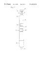
- FIG. 1 is a side view of a pipette of the present invention to which a tip is attached.
- FIG. 2 is a side view of the pipette from which the tip is detached.
- FIG. 3 is a front view of the pipette from which the tip is detached.
- FIG. 4 is a vertical cross section of the pipette from which the tip is detached.
- FIG. 5 is an enlarged vertical cross section showing the tip side portion of the pipette.
- FIG. 6 is an enlarged vertical cross section showing the top side portion of the pipette.
- FIG. 7 is a cross section taken on line VII—VII of FIG. 4 .
- FIG. 8 is an exploded perspective view showing a cylinder, a first piston, a second piston and so on.
- FIG. 9 is an exploded perspective view showing an operating lever.
- FIG. 10 is a vertical cross section of the pipette to which the tip is attached.
- FIG. 11 is a vertical cross section showing a state that the tip is attached to the nozzle.
- FIG. 12 is a vertical cross section showing a state that the tip is released from the nozzle.
- FIG. 13 is a vertical cross section of the tip.
- FIG. 14 is an enlarged vertical cross section of a root portion of the tip.
- FIG. 15 is an enlarged vertical cross section of a distal end portion of the tip.
- FIG. 16 is an enlarged vertical cross section showing a part where the tip is attached to the nozzle.
- FIG. 17 is a vertical cross section showing the pipette under operation in a small suction position.
- FIG. 18 is a vertical cross section showing the pipette under operation in a large suction position.
- a pipette 1 is for transferring various kinds of liquid samples from one vessel to another vessel.
- the pipette 1 is so constructed that selection can be made between sampling a large amount of liquid and sampling a small amount of liquid.
- a cylinder 3 In a casing 2 of the pipette 1 , a cylinder 3 , a first piston 4 , a second piston 5 , an operating lever 6 and so on are housed.
- the casing 2 has a body part 21 , an end cap 22 fitted on a tip end portion of the body part 21 , and a head cap 23 fitted in a top end portion of the body part 21 .
- the body part 21 is internally formed with a hollow core 2 s whose both end surfaces are open. In the core 2 s, a large-diameter hole 24 on the tip end side and a small-diameter hole 25 on the top side are continuously formed via a shoulder.
- the outline of the body part 21 is approximately elliptical in cross section.
- the body part 21 has a plurality of anti-slipping lateral grooves 26 formed in the side surface thereof on the opposite side of a clip 81 . Namely, the lateral grooves 26 are formed to prevent slippage of the body part 21 so that the body part 21 can be gripped readily and reliability with a palm and fingers.
- the cylinder 3 includes a cylinder body 31 and a nozzle 33 .
- a flange 32 is formed at a lower end of a cylinder body 31 .
- the nozzle 33 and the cylinder body 31 are formed in one piece.
- the cylinder body 31 is inserted into the large-diameter hole 24 of the body part 21 of the casing 2 .
- the flange 32 is formed so as to have a diameter as large as the tip end surface of the body part 21 and come into contact with it.
- the cylinder body 31 is internally formed with a first suction chamber 34 open on an inward end surface thereof located at the upper end in FIG. 5 .
- the first piston 4 includes a cylindrical piston body 41 and a flange 42 integrally formed at lone end of the piston body 41 .
- An inner space of the first piston 4 is formed into a second suction chamber 43 whose both end surfaces are open.
- the piston body 41 is reciprocatably inserted into the first suction chamber 34 and comes into air-tight contact with the cylinder 3 through a sealing ring 13 .
- the flange 42 of the first piston 4 is formed in a diameter to allow contact with the large-diameter hole 24 of the casing 2 .
- a first spring 44 as a first resilient member is interposed between the flange 42 and the cylinder body 31 .
- the first spring 44 pushes the first piston 4 in a direction to extend it.
- the flange 42 is brought into contact with the shoulder formed between the large-diameter hole 24 and the small-diameter hole 25 of the body part 21 . In this manner, the first piston 4 is kept in its extreme extended position.
- the second piston 5 includes a bar-shaped piston body 51 and a flange 52 integrally formed at one end of the piston body 51 .
- the piston body 51 consists of a large-diameter part 5 a and a small-diameter part 5 b.
- the small-diameter part 5 b of the piston body 51 is reciprocatably inserted into the second suction chamber 43 , and comes into air-tight contact with the first piston 4 through a sealing ring 14 .
- the large-diameter part 5 a of the piston body 51 is formed so as to be abuttable against the flange 42 of the first piston 4 .
- the flange 52 of the second piston 5 is formed in a diameter to allow contact with the small-diameter hole 25 of the casing 2 .
- a second spring 53 as a second resilient member is interposed between the flange 52 of the second piston 5 and the flange 42 of the first piston 4 .
- the second spring 53 pushes the second piston 5 in a direction to extend it.
- the second spring 53 is set to have less resiliency than the first spring 44 . Thereby, the second piston 5 is kept in its extreme extended position with the operating lever 6 in contact with the flange 52 .
- a retaining member 15 for retaining the sealing ring 14 is interposed.
- the operating lever 6 includes a knocking mechanism, and the knocking mechanism includes a rotor 61 , a guide member 62 , a knocking member 63 and a knocking cover 64 .
- the operating lever 6 is provided movably along the axis of the casing 2 , and is constructed to operate the first and second pistons 4 and 5 to switch between a small suction position and a large suction position.
- the small suction position is a position where the second piston 5 is extremely retracted in the first piston 4
- the large suction position is a position where the first and second pistons 4 and 5 are extremely retracted in the cylinder 3 and the first piston 4 , respectively.
- the guide member 62 is formed in an approximately cylindrical shape, and is fixedly fitted in a top part of the small-diameter hole 25 of the body, part 21 of the casing 2 .
- the guide member 62 has a plurality of slide grooves 6 a, 6 a, . . .
- the plurality of, for example, six slide grooves 6 a, 6 a, . . . are each opened at one end thereof (lower end of FIG. 9 ).
- Strips 6 b, 6 b, ... between the adjacent slide grooves 6 a, 6 a, . . . are each formed such that a bottom surface thereof is inclined from one to another of two adjacent slide grooves 6 a, 6 a.
- the rotor 61 includes a small-diameter shaft part 6 c and a plurality of slide parts 6 d, 6 d, . . .
- the plurality of slide parts 6 d, 6 d, . . . are formed to extend axially from one end (lower end in FIG. 9) of the shaft part 6 c, and are formed continuously with the shaft part 6 c.
- the rotor 61 is disposed such that the bottom surface thereof comes into contact with the flange 52 of the second piston 5 and the shaft part 6 c coaxially passes through the guide member 62 .
- the slide parts 6 d, 6 d, . . . are provided by the half number of slide grooves 6 a, 6 a, . . .
- the slide parts 6 d, 6 d, . . . have inclined top surfaces corresponding to the inclined bottom surfaces of the strips 6 b, 6 b, . . . , respectively, so as to be capable of freely entering and exiting from the slide grooves 6 a, 6 a, . . .
- the knocking member 63 includes a cylindrical shaft part 6 e and a plurality of cams 6 f, 6 f, ....
- the plurality of cams 6 f, 6 f, ... are each formed in an approximately elliptical shape, and are formed continuously from one end (lower end in FIG. 9) of the shaft part 6 e.
- the shaft part 6 e of the knocking member 63 coaxially passes through the guide member 62 , and the shaft part 6 c of the rotor 61 is inserted into the shaft part 6 e.
- the cams 6 f, 6 f, . . . are provided by the number corresponding to the number of slide grooves 6 a, 6 a, . . .
- the knocking cover 64 includes a shaft part 6 g and a push part 6 h.
- the push part 6 h is formedin a disk-like shape, and is integrally formed at one end (upper end in FIG. 6) of the shaft part 6 g.
- the lower end of the shaft part 6 g passes through the head cap 23 of the casing 2 and is fitted on the shaft part 6 e of the knocking member 63 , so that the knocking cover 64 is disposed coaxially with the knocking member 63 .
- the cams 6 f, 6 f, . . . push the slide parts 6 d, 6 d, . . . downward.
- the slide parts 6 d, 6 d exit from the slide grooves 6 a, 6 a, . . .
- the rotor 61 rotates and the second piston 5 is set in the small suction position.
- the nozzle 33 of the cylinder 3 is formed continuously with the cylinder body 31 so as to protrude from the flange 32 toward the tip end of the casing 2 , and passes through an opening 2 a of the end cap 22 .
- a root portion 3 a, an intermediate portion 3 b and a distal end portion 3 c are continuously formed.
- the root portion 3 a extends from the flange 32 and has a large diameter.
- the intermediate portion 3 b is formed in a smaller diameter than the root portion 3 a and constitutes a tip attachment part.
- the distal end portion 3 c is formed in a smaller diameter than the intermediate portion 3 b.
- the nozzle 33 is internally provided with a suction passage 3 d in communication with the first suction chamber 34 , and the suction passage 3 d is open on the distal end surface of the nozzle 33 .
- the nozzle 33 is provided with a tip 7 freely attachable thereto and detachable therefrom.
- the tip 7 is formed into a small-diameter cylinder, and has a tip body formed of a main body portion 71 and a tapered portion 72 .
- the main body portion 71 is formed into an approximately straight cylinder.
- the tapered portion 72 is formed continuously with the extension part 71 and is tapered to diminish its diameter toward the distal end of the tip 7 .
- the tip 7 is formed of a translucent material with a thickness t of, for example, 0.4 through 0.7 mm.
- the inner diameter d 1 of the main body portion 71 is for example 4.40 mm.
- an end portion of the tip 7 proximate to the opening of the main body portion 71 is formed into a receiving part 73 for receiving the nozzle 33 .
- the receiving part 73 constitutes a nozzle-fitting part in which a thick portion 7 a and an annular projection 7 b are formed.
- the thick portion 7 a is formed in an approximately truncated cone, and has a maximum outer diameter d 2 of 6.5 mm for example. Namely, the thick portion 7 a is formed larger in outer diameter than the root portion 3 a of the nozzle 33 .
- the annular projection 7 b is formed along the inner periphery of the main body portion 71 , and has a half-round cross section the curvature radius R of which is 0.5 mm thereby constituting an annular part. Further, the annular projection 7 b is formed such that its extended amount h 1 is for example 0.05 through 0.2 mm and its length h 2 from the center of the annular projection 7 b to the opening end of the main body portion 71 is 1.50 mm.
- the inner diameter d 3 at the distal end of the tapered portion 72 is for example 1.5 mm.
- a sub-portion of the tapered portion 72 along a length h 3 of 2.0 mm from the distal end thereof is formed into a straight end section 74 .
- a cylindrical releasing member 11 is axially movably attached around the root portion 3 a of the nozzle 33 .
- a compression spring 12 as a resilient member is interposed between the releasing member 11 and the end cap 22 .
- the releasing member 11 is pushed in a direction away from the distal end of the nozzle 33 by the compression spring 12 and is pressed against the flange 32 of the cylinder 3 .
- the inner diameter of the releasing member 11 is smaller than the outer diameter of the thick portion 7 a of the tip 7 .
- the releasing member 11 is constructed such that when it is moved toward the distal end of the nozzle 33 by a detaching means 8 , it abuts against the thick portion 7 a of the tip 7 and acts to detach the tip 7 from the nozzle 33 .
- annular projection 3 e is formed in the intermediate portion 3 b of the nozzle 33 .
- the annular projection 3 e is formed, like the annular projection 7 b of the tip 7 , such that the curvature radius of the cross section thereof is for example 0.5 mm and the extended amount thereof is for example 0.05 through 0.2 mm, thereby constituting an annular part.
- the annular projection 3 e is formed such that the length from the center thereof to the shoulder of the root portion 3 a is for example 2.00 mm.
- both the annular projections 7 b and 3 e are positioned such that an abutment sound indicating a feeling of fitting between the tip 7 and the nozzle 33 is produced between the opening end surface of the tip 7 and the shoulder of the nozzle 33 when the fitting therebetween is completed.
- both the annular projections 7 b and 3 e come into close contact with each other, which provides a seal between the tip 7 and the nozzle 33 .
- a sub-portion closer to the distal end than the annular projection 3 e is formed into a tapered section 3 f.
- the detaching means 8 is composed of a clip 81 and a detaching pin 82 .
- the clip 81 is provided for free movement in a mounting groove 2 b axially formed on the top part of the body part 21 of the casing 2 .
- the clip 81 is inclined on the body part 21 side to diminish its extended amount toward its distal end, thereby providing ease grip.
- the detaching pin 82 is inserted into the body part 21 of the casing 2 so as to pass through the body part 21 .
- the detaching means 8 is so constructed that when the clip 81 is pushed down from the position of FIG. 4, the detaching pin 82 moves downward and passes through the flange 32 of the cylinder 3 to push the releasing member 11 downward and the pushed releasing member 11 detaches the tip 7 from the nozzle 33 .
- the pipette 1 of FIG. 10 is in a state before sucking a liquid sample.
- the releasing member 11 comes into contact with the flange 32 of the cylinder 3
- the first piston 4 extends from the cylinder body 31
- the second piston 5 extends from the first piston 4 .
- Both the pistons 4 , 5 are in their extreme extended positions. Accordingly, the first and second suction chambers 34 and 43 each have a maximum capacity.
- the tip 7 is fitted on the nozzle 33 so as to be connected to the cylinder 3 .
- the tip-side annular projection 7 b slides over the nozzle-side annular projection 3 e and at the same time an abutment sound is produced between the opening end surface of the tip 7 and the shoulder of the nozzle 33 , thereby completing the insertion of the nozzle 33 into the tip 7 .
- the analyzer can recognize the completion of insertion based on this abutment sound.
- the tip-side annular projection 7 e and the nozzle-side annular projection 3 e are brought into close contact with each other, which provides a seal between the tip 7 and the nozzle 33 .
- FIG. 16 shows the state where the insertion of the nozzle 33 into the tip 7 is completed.
- the body part 21 of the casing 2 is griped with one hand, and the push part 6 h of the operating lever 6 is then pushed with a thumb of the hand to move the knocking cover 64 downward.
- the downward movement of the knocking cover 64 moves the knocking member 63 downward so that the slide parts 6 d, 6 d, . . . in contact with the cams 6 f, 6 f, . . . are pushed down.
- the rotor 61 is moved downward.
- the slide parts 6 d, 6 d, . . . of the rotor 61 are moved out of the slide grooves 6 a, 6 a, . . . of the guide member 62 .
- the top surfaces of the slide parts 6 d, 6 d, . . . are brought into contact with the bottom surfaces of the strips 6 b, 6 b, . . .
- the position of the rotor 61 after rotation is shown in FIG. 17 .
- the end surface of the large-diameter part 5 a of the piston body 51 of the second piston 5 comes close to the flange 42 of the first piston 4 with the retaining member 15 sandwiched therebetween.
- the small-diameter part 5 b of the second piston 5 is made deepest inserted into the second suction chamber 43 , so that the second piston 5 is set in the small suction position for sampling a small amount of liquid.
- the second piston 5 comes to the small suction position.
- the capacity in the small suction position is set at a sampling amount of, for example, 15 ⁇ l.
- the pipette 1 comes into the state shown in FIG. 18, i.e., the state that the piston body 41 of the first piston 4 is made deepest inserted into the first suction chamber 34 .
- the first piston 4 is deepest inserted into the first suction chamber 34 in the state that, the second piston 5 is deepest inserted into the second suction chamber 43 , so that the first piston 4 is set in the large suction position for sampling a large amount of liquid.
- the capacity in the large suction position is set at a sampling amount of, for example, 500 ⁇ l.
- the first and second pistons 4 and 5 extend by the resiliency of the first and second springs 44 and 53 to come back into the initial state of FIG. 10 .
- picked urine is first centrifuged, the supernatant fluid is removed and a sample including 200 ⁇ l of liquid is prepared.
- the pipette 1 is first put into the large suction position where the knocking cover 64 is deepest pushed down (See FIG. 18 ). In this state, the tip 7 is put in a liquid in a vessel for sample picking, the knocking cover 64 is then moved backward until the amount of liquid in the vessel reaches 200 ⁇ l, and the supernatant fluid is removed.
- the knocking cover 64 is adequately pushed down to supply air into the sample and the sample is stirred. Then, from the mixture, 15 ⁇ l of liquid sample for an urine precipitation test is picked up. For this purpose, the pipette 1 is put into the small suction position where the knocking cover 64 is slightly pushed down (See FIG. 17 ). In this state, the tip 7 is put in the liquid sample in the vessel for sample picking, and the knocking cover 64 is then moved backward to pick up the liquid sample.
- the clip 81 is pushed down to move the detaching pin 82 downward so that the releasing member 11 moves downward.
- the bottom end thereof abuts against the thick portion 7 a of the tip 7 to detach the tip 7 from the nozzle 33 , though the case is not shown.
- the annular projection 7 b provided along the inner periphery of the tip 7 forms a seal between the tip 7 and the nozzle 33 , the attachment of the tip 7 can be made with reliability. As a result, a large number of samples can be analyzed promptly and reliably.
- annular projections 7 b and 3 e, provided in the tip 7 and the nozzle 33 , respectively, form a seal therebetween and a sound of abutment therebetween is produced at the position where the insertion of the nozzle 33 into the tip 7 is completed, the attachment of the tip 7 can be correctly recognized.
- the pipette of the present embodiment enables prompt analyses of a large number of samples in such a case.
- annular projection 7 b of the tip 7 comes into close contact with the annular projection 3 e of the nozzle 33 by snapping over the annular projection 3 e of the nozzle 33 , a seal can reliably be provided between the tip 7 and the nozzle 33 . Accordingly, sucking liquid can be made correctly, which provides an improved analyzing accuracy.
- the release of the tip 7 is implemented by simply snapping out the annular projection 7 b of the tip 7 over the annular projection 3 e of the nozzle 3 , and therefore a contact area between the tip 7 and the nozzle 33 is small. Accordingly, the release of the tip 7 can be made readily. As a result, the tip 7 can be released with one hand, which provides improved workability.
- the tip 7 can be detached through the operation of the clip 81 alone.
- samples are avoided from touch with hand, which enables the analysis or the like to be executed in a prompt and considerably sanitary manner.
- the pipette of the present embodiment provides an extended range of applications as compared with the conventional pipette whose sampling amount is limited to a fixed amount.
- a necessary amount of liquid can readily be sampled, which achieves prompt analyzing.
- the pipette of the present embodiment can simplify the structure and reduce the number of parts as compared with the conventional pipette of the capacity-variable type whose sampling amount is arbitrarily set, this reduces the manufacturing cost.
- selection between the large amount sampling and the small amount sampling can be made with one hand, i.e., at the push of the push part 6 h with a thumb.
- operation can be simplified thereby speeding up the execution of various kinds of analyses.
- the tip-side annular projection 7 b and the nozzle-side annular projection 3 e are positioned such that an abutment sound is produced between the end surface of the tip 7 and the shoulder of the nozzle 33 .
- the fitting structure between the tip and the nozzle in the present invention may not necessarily produce such an abutment sound.
- first and second pistons 4 and 5 are provided. In the present invention, however, two pistons may not necessarily be provided and the sampling amount may be fixed.
- the shape of the annular projections 3 e, 7 b is not limited to a half-round cross section as employed in the above embodiment. Cams in an elliptical shape or other shapes may be employed for an annular part of the present invention.
- annular projections 3 e and 7 b may have different shapes from each other.
- each of the annular projections 3 e and 7 b provided may be two or more in number.
- the shape of the thick portion 7 b of the tip 7 is not limited to a truncated cone, and the thick portion 7 b may have a ring shape or any other shape. In essence, the thick portion 7 b may have a shape to allow abutment against the releasing member 11 .
- the first spring 44 , the second spring 53 and the compression spring 12 are not limited to coil springs shown in the above embodiment.
- various kinds of resilient members such as a leaf spring and a piece of rubber are applicable.
Abstract
Description
Claims (9)
Priority Applications (1)
| Application Number | Priority Date | Filing Date | Title |
|---|---|---|---|
| US09/468,858 US6499363B1 (en) | 1997-12-12 | 1999-12-21 | Tip for pipette and pipette with the same |
Applications Claiming Priority (2)
| Application Number | Priority Date | Filing Date | Title |
|---|---|---|---|
| US08/989,775 US6021680A (en) | 1995-06-09 | 1997-12-12 | Pipette |
| US09/468,858 US6499363B1 (en) | 1997-12-12 | 1999-12-21 | Tip for pipette and pipette with the same |
Related Parent Applications (1)
| Application Number | Title | Priority Date | Filing Date |
|---|---|---|---|
| US08/989,775 Continuation-In-Part US6021680A (en) | 1995-06-09 | 1997-12-12 | Pipette |
Publications (1)
| Publication Number | Publication Date |
|---|---|
| US6499363B1 true US6499363B1 (en) | 2002-12-31 |
Family
ID=25535449
Family Applications (1)
| Application Number | Title | Priority Date | Filing Date |
|---|---|---|---|
| US09/468,858 Expired - Fee Related US6499363B1 (en) | 1997-12-12 | 1999-12-21 | Tip for pipette and pipette with the same |
Country Status (1)
| Country | Link |
|---|---|
| US (1) | US6499363B1 (en) |
Cited By (21)
| Publication number | Priority date | Publication date | Assignee | Title |
|---|---|---|---|---|
| US20030177849A1 (en) * | 2000-08-18 | 2003-09-25 | Takeski Matsuda | Pipet device with disposable tip |
| US20050155438A1 (en) * | 2004-01-21 | 2005-07-21 | Herbert Belgardt | Pipetting device with a displacement device and a drive device releasably connected therewith |
| US20050155439A1 (en) * | 2004-01-21 | 2005-07-21 | Herbert Belgardt | Pipetting device with an ejection device for pipette tips |
| US20050175511A1 (en) * | 2004-02-11 | 2005-08-11 | Cote Richard A. | Pipette tip mounting and ejection assembly and associated pipette tip |
| US20050204832A1 (en) * | 2004-03-06 | 2005-09-22 | Jessop Paul M | Pipette tip for easy separation |
| US7033543B1 (en) * | 1999-04-16 | 2006-04-25 | Hamilton Bonaduz Ag | Pipette tip, pipetting device and combination consisting of a pipette tip and pipetting device |
| WO2006087444A1 (en) * | 2005-02-18 | 2006-08-24 | Gilson S.A.S. | Tip for sampling pipette and pipette thus equipped |
| US20080006100A1 (en) * | 2006-07-07 | 2008-01-10 | Eppendorf Ag | Pipetting device |
| US7335337B1 (en) * | 2001-09-11 | 2008-02-26 | Smith James C | Ergonomic pipette tip and adapters |
| US20080078258A1 (en) * | 2006-09-28 | 2008-04-03 | Price West L | Multi-component pipette tip and associated methods |
| US20080233013A1 (en) * | 2007-03-20 | 2008-09-25 | Ichiro Sakai | Dispensing nozzle tip |
| US20100034706A1 (en) * | 2006-10-24 | 2010-02-11 | Viaflo Corporation | Disposable Pipette Tip |
| US20100166616A1 (en) * | 2007-09-19 | 2010-07-01 | Price West L | Pipette tip rack and associated methods |
| EP2687292A1 (en) * | 2006-10-24 | 2014-01-22 | Integra Biosciences Corp. | Locking pipette tip and mounting shaft |
| US20140199216A1 (en) * | 2013-01-15 | 2014-07-17 | Rainin Instrument, Llc | Liquid end assembly for a multichannel air displacement pipette |
| US20150209777A1 (en) * | 2014-01-30 | 2015-07-30 | Rainin Instrument, Llc | Air displacement pipette with enhanced blowout |
| US20170014858A1 (en) * | 2015-07-14 | 2017-01-19 | Shofu Inc. | Applicator with plunger having movable range restricted by resistance structure |
| US9901920B1 (en) * | 2016-06-15 | 2018-02-27 | Hamilton Company | Pipetting device, pipette tip coupler, and pipette tip: devices and methods |
| US10898892B2 (en) | 2016-06-15 | 2021-01-26 | Hamilton Company | Pipetting device, pipette tip coupler, and pipette tip: devices and methods |
| US11065614B2 (en) | 2016-06-15 | 2021-07-20 | Hamilton Company | Pipetting device, pipette tip coupler, and pipette tip: devices and methods |
| US11235318B2 (en) | 2016-06-15 | 2022-02-01 | Hamilton Company | Pipetting device, pipette tip coupler, and pipette tip: devices and methods |
Citations (19)
| Publication number | Priority date | Publication date | Assignee | Title |
|---|---|---|---|---|
| US4036064A (en) | 1975-09-11 | 1977-07-19 | Gilford Instrument Laboratories, Inc. | Pipette device |
| US4105522A (en) * | 1973-06-15 | 1978-08-08 | Friedenberg Robert M | Glucose level test apparatus |
| GB2029723A (en) * | 1978-09-12 | 1980-03-26 | Lee T | Adjustable volume pipetting device |
| US4237095A (en) * | 1978-04-25 | 1980-12-02 | Kommandiittiyhtio Finnpipette Osmo A. Suovaniemi | Tip vessel for use in connection with a dosage pipette |
| US4284213A (en) * | 1980-07-07 | 1981-08-18 | Dow Corning Corporation | Closure and nozzle system for container for air-curable material |
| JPS6234587A (en) | 1985-08-09 | 1987-02-14 | 松下電工株式会社 | Electric razor |
| US4768954A (en) * | 1982-03-16 | 1988-09-06 | Dragan William B | Syringe tip |
| US4961350A (en) * | 1988-07-21 | 1990-10-09 | Firma Eppendorf-Netheler-Hinz Gmbh | Fittable pipette tip consisting of a vessel which is designed to fit a particularly conical fitting head of a pipette |
| US5024654A (en) * | 1989-10-02 | 1991-06-18 | Alcon Surgical, Inc. | Insulated infusion and aspiration probe |
| US5027872A (en) * | 1988-08-11 | 1991-07-02 | Imperial Chemical Industries Plc | System for introducing additive into a container |
| JPH0623283A (en) | 1992-04-21 | 1994-02-01 | Labsystems Oy | Pipette with tip remover |
| JPH06210188A (en) | 1992-09-28 | 1994-08-02 | Gilson Medical Electronics Fr Sa | Pipette for sampling and distributing liquid |
| JPH07284674A (en) * | 1994-04-20 | 1995-10-31 | Fuji Photo Film Co Ltd | Pipette tip |
| JPH08313403A (en) | 1995-05-23 | 1996-11-29 | Masamichi Otani | Pipette apparatus |
| US5580529A (en) * | 1994-04-22 | 1996-12-03 | Bio-Plas, Inc. | Aerosol and liquid transfer resistant pipette tip apparatus |
| FR2772006A1 (en) * | 1997-12-04 | 1999-06-11 | Bernard Guillermier | OUTPUT DEVICE FOR FLUID CONTAINER |
| US6030582A (en) * | 1998-03-06 | 2000-02-29 | Levy; Abner | Self-resealing, puncturable container cap |
| US6116099A (en) * | 1996-11-18 | 2000-09-12 | Carl; Richard A. | Liquid dispensing apparatus having means for loading pipette tips onto fluid dispensing cylinders |
| US6315549B1 (en) * | 1999-03-19 | 2001-11-13 | Husky Injection Molding Systems Ltd. | Hot tip insulator retainer |
-
1999
- 1999-12-21 US US09/468,858 patent/US6499363B1/en not_active Expired - Fee Related
Patent Citations (21)
| Publication number | Priority date | Publication date | Assignee | Title |
|---|---|---|---|---|
| US4105522A (en) * | 1973-06-15 | 1978-08-08 | Friedenberg Robert M | Glucose level test apparatus |
| US4036064A (en) | 1975-09-11 | 1977-07-19 | Gilford Instrument Laboratories, Inc. | Pipette device |
| US4237095A (en) * | 1978-04-25 | 1980-12-02 | Kommandiittiyhtio Finnpipette Osmo A. Suovaniemi | Tip vessel for use in connection with a dosage pipette |
| GB2029723A (en) * | 1978-09-12 | 1980-03-26 | Lee T | Adjustable volume pipetting device |
| US4284213A (en) * | 1980-07-07 | 1981-08-18 | Dow Corning Corporation | Closure and nozzle system for container for air-curable material |
| US4768954A (en) * | 1982-03-16 | 1988-09-06 | Dragan William B | Syringe tip |
| JPS6234587A (en) | 1985-08-09 | 1987-02-14 | 松下電工株式会社 | Electric razor |
| US4961350A (en) * | 1988-07-21 | 1990-10-09 | Firma Eppendorf-Netheler-Hinz Gmbh | Fittable pipette tip consisting of a vessel which is designed to fit a particularly conical fitting head of a pipette |
| US5027872A (en) * | 1988-08-11 | 1991-07-02 | Imperial Chemical Industries Plc | System for introducing additive into a container |
| US5024654A (en) * | 1989-10-02 | 1991-06-18 | Alcon Surgical, Inc. | Insulated infusion and aspiration probe |
| JPH0623283A (en) | 1992-04-21 | 1994-02-01 | Labsystems Oy | Pipette with tip remover |
| US5435197A (en) | 1992-04-21 | 1995-07-25 | Labsystems Oy | Pipette with a tip remover |
| JPH06210188A (en) | 1992-09-28 | 1994-08-02 | Gilson Medical Electronics Fr Sa | Pipette for sampling and distributing liquid |
| US5413006A (en) | 1992-09-28 | 1995-05-09 | Gilson Medical Electronics (France) S.A. | Pipette for sampling and dispensing adjustable volumes of liquids |
| JPH07284674A (en) * | 1994-04-20 | 1995-10-31 | Fuji Photo Film Co Ltd | Pipette tip |
| US5580529A (en) * | 1994-04-22 | 1996-12-03 | Bio-Plas, Inc. | Aerosol and liquid transfer resistant pipette tip apparatus |
| JPH08313403A (en) | 1995-05-23 | 1996-11-29 | Masamichi Otani | Pipette apparatus |
| US6116099A (en) * | 1996-11-18 | 2000-09-12 | Carl; Richard A. | Liquid dispensing apparatus having means for loading pipette tips onto fluid dispensing cylinders |
| FR2772006A1 (en) * | 1997-12-04 | 1999-06-11 | Bernard Guillermier | OUTPUT DEVICE FOR FLUID CONTAINER |
| US6030582A (en) * | 1998-03-06 | 2000-02-29 | Levy; Abner | Self-resealing, puncturable container cap |
| US6315549B1 (en) * | 1999-03-19 | 2001-11-13 | Husky Injection Molding Systems Ltd. | Hot tip insulator retainer |
Cited By (64)
| Publication number | Priority date | Publication date | Assignee | Title |
|---|---|---|---|---|
| US7033543B1 (en) * | 1999-04-16 | 2006-04-25 | Hamilton Bonaduz Ag | Pipette tip, pipetting device and combination consisting of a pipette tip and pipetting device |
| US6874379B2 (en) * | 2000-08-18 | 2005-04-05 | Arkray, Inc. | Pipet device with disposable tip |
| US20030177849A1 (en) * | 2000-08-18 | 2003-09-25 | Takeski Matsuda | Pipet device with disposable tip |
| US20080095665A1 (en) * | 2001-09-11 | 2008-04-24 | Smith James C | Ergonomic pipette tip and adapters |
| US7335337B1 (en) * | 2001-09-11 | 2008-02-26 | Smith James C | Ergonomic pipette tip and adapters |
| US8071050B2 (en) | 2001-09-11 | 2011-12-06 | Smith James C | Ergonomic pipette tip and adapters |
| US7320260B2 (en) * | 2004-01-21 | 2008-01-22 | Eppendorf Ag | Pipetting device with a displacement device and a drive device releasably connected therewith |
| US7434484B2 (en) * | 2004-01-21 | 2008-10-14 | Eppendorf Ag | Pipetting device with an ejection device for pipette tips |
| US20050155438A1 (en) * | 2004-01-21 | 2005-07-21 | Herbert Belgardt | Pipetting device with a displacement device and a drive device releasably connected therewith |
| US20050155439A1 (en) * | 2004-01-21 | 2005-07-21 | Herbert Belgardt | Pipetting device with an ejection device for pipette tips |
| US20050175511A1 (en) * | 2004-02-11 | 2005-08-11 | Cote Richard A. | Pipette tip mounting and ejection assembly and associated pipette tip |
| EP2311566A1 (en) * | 2004-02-11 | 2011-04-20 | Matrix Technologies Corporation | Pipette tip mounting and ejection assembly and associated pipette tip |
| CN1984717B (en) * | 2004-02-11 | 2010-11-17 | 马特里克斯技术公司 | Pipette tip mounting and ejection assembly and associated pipette tip |
| AU2005216853B2 (en) * | 2004-02-11 | 2010-07-29 | Matrix Technologies Corporation | Pipette tip mounting and ejection assembly and associated pipette tip |
| US8163256B2 (en) | 2004-02-11 | 2012-04-24 | Matrix Technologies Corporation | Pipette tip mounting and ejection assembly and associated pipette tip |
| US7641859B2 (en) | 2004-02-11 | 2010-01-05 | Matrix Technologies Corporation | Pipette tip mounting and ejection assembly and associated pipette tip |
| WO2005082536A1 (en) * | 2004-02-11 | 2005-09-09 | Matrix Technologies Corporation | Pipette tip mounting and ejection assembly and associated pipette tip |
| US20090280033A1 (en) * | 2004-02-11 | 2009-11-12 | Matrix Technologies Corporation | Pipette Tip Mounting And Ejection Assembly And Associated Pipette Tip |
| US7320259B2 (en) | 2004-03-06 | 2008-01-22 | Medax International, Inc. | Pipette tip for easy separation |
| US20050204832A1 (en) * | 2004-03-06 | 2005-09-22 | Jessop Paul M | Pipette tip for easy separation |
| US8480972B2 (en) | 2005-02-18 | 2013-07-09 | Gilson S.A.S. | Shaft for a sampling pipette |
| US20070297948A1 (en) * | 2005-02-18 | 2007-12-27 | Yves May | Shaft for a sampling pipette |
| WO2006087444A1 (en) * | 2005-02-18 | 2006-08-24 | Gilson S.A.S. | Tip for sampling pipette and pipette thus equipped |
| FR2882273A1 (en) * | 2005-02-18 | 2006-08-25 | Gilson Sas Soc Par Actions Sim | TIP FOR TAKING PIPETTE, AND PIPETTE THUS EQUIPPED |
| WO2006093925A3 (en) * | 2005-02-28 | 2007-04-12 | Medax International Inc | Pipette tip for easy separation |
| WO2006093925A2 (en) * | 2005-02-28 | 2006-09-08 | Medax International, Inc. | Pipette tip for easy separation |
| US7673532B2 (en) * | 2006-07-07 | 2010-03-09 | Eppendael AG | Pipetting device |
| US20080006100A1 (en) * | 2006-07-07 | 2008-01-10 | Eppendorf Ag | Pipetting device |
| US20080078258A1 (en) * | 2006-09-28 | 2008-04-03 | Price West L | Multi-component pipette tip and associated methods |
| US20100034706A1 (en) * | 2006-10-24 | 2010-02-11 | Viaflo Corporation | Disposable Pipette Tip |
| US8877513B2 (en) | 2006-10-24 | 2014-11-04 | Integra Biosciences Ag | Method of using a disposable pipette tip |
| US8501118B2 (en) * | 2006-10-24 | 2013-08-06 | Integra Biosciences Corp. | Disposable pipette tip |
| EP2687292A1 (en) * | 2006-10-24 | 2014-01-22 | Integra Biosciences Corp. | Locking pipette tip and mounting shaft |
| US9333500B2 (en) | 2006-10-24 | 2016-05-10 | Integra Biosciences Ag | Locking pipette tip and mounting shaft in hand-held manual pipette |
| EP1977831A3 (en) * | 2007-03-20 | 2008-10-22 | Hitachi High-Technologies Corporation | Dispensing nozzle tip |
| US8293192B2 (en) | 2007-03-20 | 2012-10-23 | Hitachi High-Technologies Corporation | Dispensing nozzle tip |
| US20080233013A1 (en) * | 2007-03-20 | 2008-09-25 | Ichiro Sakai | Dispensing nozzle tip |
| US20100166616A1 (en) * | 2007-09-19 | 2010-07-01 | Price West L | Pipette tip rack and associated methods |
| US20140199216A1 (en) * | 2013-01-15 | 2014-07-17 | Rainin Instrument, Llc | Liquid end assembly for a multichannel air displacement pipette |
| US9815053B2 (en) * | 2013-01-15 | 2017-11-14 | Mettler-Toledo Rainin, LLC | Liquid end assembly for a multichannel air displacement pipette |
| US20150209777A1 (en) * | 2014-01-30 | 2015-07-30 | Rainin Instrument, Llc | Air displacement pipette with enhanced blowout |
| US9221046B2 (en) * | 2014-01-30 | 2015-12-29 | Rainin Instrument, Llc | Air displacement pipette with enhanced blowout |
| CN106413897B (en) * | 2014-01-30 | 2019-10-18 | 梅特勒-托利多瑞宁有限责任公司 | Exhaust pipette with enhancing blowout |
| CN106413897A (en) * | 2014-01-30 | 2017-02-15 | 瑞宁器材公司 | Air displacement pipette with enhanced blowout |
| US20170014858A1 (en) * | 2015-07-14 | 2017-01-19 | Shofu Inc. | Applicator with plunger having movable range restricted by resistance structure |
| US9943842B2 (en) * | 2016-06-15 | 2018-04-17 | Hamilton Company | Pipetting device, pipette tip coupler, and pipette tip: devices and methods |
| US9962707B2 (en) * | 2016-06-15 | 2018-05-08 | Hamilton Company | Pipetting device, pipette tip coupler, and pipette tip: devices and methods |
| US20180133716A1 (en) * | 2016-06-15 | 2018-05-17 | Hamilton Company | Pipetting Device, Pipette Tip Coupler, and Pipette Tip: Devices and Methods |
| US9901920B1 (en) * | 2016-06-15 | 2018-02-27 | Hamilton Company | Pipetting device, pipette tip coupler, and pipette tip: devices and methods |
| US10464059B1 (en) | 2016-06-15 | 2019-11-05 | Hamilton Company | Pipetting device, pipette tip coupler, and pipette tip: devices and methods |
| US10525460B2 (en) | 2016-06-15 | 2020-01-07 | Hamilton Company | Pipetting device, pipette tip coupler, and pipette tip: devices and methods |
| US10603666B1 (en) | 2016-06-15 | 2020-03-31 | Hamilton Company | Pipetting device, pipette tip coupler, and pipette tip: devices and methods |
| US10661269B2 (en) | 2016-06-15 | 2020-05-26 | Hamilton Company | Pipetting device, pipette tip coupler, and pipette tip: devices and methods |
| US10682642B2 (en) | 2016-06-15 | 2020-06-16 | Hamilton Company | Pipetting device, pipette tip coupler, and pipette tip: devices and methods |
| US10730040B2 (en) | 2016-06-15 | 2020-08-04 | Hamilton Company | Pipetting device, pipette tip coupler, and pipette tip: devices and methods |
| US10766035B1 (en) | 2016-06-15 | 2020-09-08 | Hamilton Company | Pipetting device, pipette tip coupler, and pipette tip: devices and methods |
| US10888858B2 (en) | 2016-06-15 | 2021-01-12 | Hamilton Company | Pipetting device, pipette tip coupler, and pipette tip: devices and methods |
| US10898892B2 (en) | 2016-06-15 | 2021-01-26 | Hamilton Company | Pipetting device, pipette tip coupler, and pipette tip: devices and methods |
| US11020738B2 (en) | 2016-06-15 | 2021-06-01 | Hamilton Company | Pipetting device, pipette tip coupler, and pipette tip: devices and methods |
| US11065614B2 (en) | 2016-06-15 | 2021-07-20 | Hamilton Company | Pipetting device, pipette tip coupler, and pipette tip: devices and methods |
| US11065613B2 (en) | 2016-06-15 | 2021-07-20 | Hamilton Company | Pipetting device, pipette tip coupler, and pipette tip: devices and methods |
| US11117125B2 (en) | 2016-06-15 | 2021-09-14 | Hamilton Company | Pipetting device, pipette tip coupler, and pipette tip: devices and methods |
| US11130123B2 (en) | 2016-06-15 | 2021-09-28 | Hamilton Company | Pipetting device, pipette tip coupler, and pipette tip: devices and methods |
| US11235318B2 (en) | 2016-06-15 | 2022-02-01 | Hamilton Company | Pipetting device, pipette tip coupler, and pipette tip: devices and methods |
Similar Documents
| Publication | Publication Date | Title |
|---|---|---|
| US6499363B1 (en) | Tip for pipette and pipette with the same | |
| US4009611A (en) | Hand-held micropipettor with improved pipette tip ejector | |
| US6021680A (en) | Pipette | |
| US20070282362A1 (en) | Sampler Device | |
| US11084030B2 (en) | Pipette for sampling an extended range of volumes of liquid | |
| US4054062A (en) | Hand-held micropipettor with improved accuracy of liquid volumes transferred | |
| US8117927B2 (en) | Pipette providing sampling via back-and-forth movement of the piston | |
| EP1296762A2 (en) | Automatic pipette with tip identification and detipping mechanism | |
| JP2003516232A (en) | Adjustable pipette | |
| US7204163B2 (en) | Mechanical piston pipette | |
| KR100645860B1 (en) | Pipette with simplified disassembly | |
| IE42303B1 (en) | A pipette | |
| EP1085944B1 (en) | Suction device with means for removing a replaceable tip | |
| JP5502303B2 (en) | Pipette device | |
| KR20020087952A (en) | Liquid sample pipette with tip ejecting mechanism | |
| US6158292A (en) | Pipette | |
| US5445797A (en) | Micro-pipettor assembly | |
| CN214261937U (en) | Precise liquid transfer device | |
| GB2417756A (en) | Quick fit ball joint | |
| JPS6119930B2 (en) | ||
| KR102427246B1 (en) | A mini pipette | |
| CN218250320U (en) | Spring reset structure for wide-range multi-channel liquid shifter | |
| TWI780589B (en) | Automated pipetting equipment, multi-channel pipetting assembly and pipetting structure | |
| CN219701951U (en) | Sampling tube capable of adding sample | |
| WO2022108177A1 (en) | Socket for coupling capillary tip |
Legal Events
| Date | Code | Title | Description |
|---|---|---|---|
| AS | Assignment |
Owner name: SAILOR PEN CO., LTD., THE, JAPAN Free format text: ASSIGNMENT OF ASSIGNORS INTEREST;ASSIGNORS:MORIMOTO, ICHIRO;SHIGEMATSU, KIYOTO;SHIMADA, ISAO;AND OTHERS;REEL/FRAME:010475/0007 Effective date: 19991216 Owner name: ITOCHU CORPORATION, JAPAN Free format text: ASSIGNMENT OF ASSIGNORS INTEREST;ASSIGNORS:MORIMOTO, ICHIRO;SHIGEMATSU, KIYOTO;SHIMADA, ISAO;AND OTHERS;REEL/FRAME:010475/0007 Effective date: 19991216 |
|
| CC | Certificate of correction | ||
| AS | Assignment |
Owner name: ATLETA INCORPORATION, JAPAN Free format text: ASSIGNMENT OF ASSIGNORS INTEREST;ASSIGNOR:ITOCHU CORPORATION;REEL/FRAME:014662/0356 Effective date: 20031022 |
|
| FPAY | Fee payment |
Year of fee payment: 4 |
|
| REMI | Maintenance fee reminder mailed | ||
| LAPS | Lapse for failure to pay maintenance fees | ||
| STCH | Information on status: patent discontinuation |
Free format text: PATENT EXPIRED DUE TO NONPAYMENT OF MAINTENANCE FEES UNDER 37 CFR 1.362 |
|
| FP | Expired due to failure to pay maintenance fee |
Effective date: 20101231 |