US6505083B1 - Apparatus for assembling a disc storage system including a modular input/output board - Google Patents
Apparatus for assembling a disc storage system including a modular input/output board Download PDFInfo
- Publication number
- US6505083B1 US6505083B1 US09/409,755 US40975599A US6505083B1 US 6505083 B1 US6505083 B1 US 6505083B1 US 40975599 A US40975599 A US 40975599A US 6505083 B1 US6505083 B1 US 6505083B1
- Authority
- US
- United States
- Prior art keywords
- modular
- input
- board
- output
- couple
- Prior art date
- Legal status (The legal status is an assumption and is not a legal conclusion. Google has not performed a legal analysis and makes no representation as to the accuracy of the status listed.)
- Expired - Fee Related
Links
Images


Classifications
-
- G—PHYSICS
- G11—INFORMATION STORAGE
- G11B—INFORMATION STORAGE BASED ON RELATIVE MOVEMENT BETWEEN RECORD CARRIER AND TRANSDUCER
- G11B25/00—Apparatus characterised by the shape of record carrier employed but not specific to the method of recording or reproducing, e.g. dictating apparatus; Combinations of such apparatus
- G11B25/04—Apparatus characterised by the shape of record carrier employed but not specific to the method of recording or reproducing, e.g. dictating apparatus; Combinations of such apparatus using flat record carriers, e.g. disc, card
- G11B25/043—Apparatus characterised by the shape of record carrier employed but not specific to the method of recording or reproducing, e.g. dictating apparatus; Combinations of such apparatus using flat record carriers, e.g. disc, card using rotating discs
Definitions
- the present invention relates generally to disc storage systems. More particularly, the present invention relates to an apparatus for use in assembling disc storage systems.
- Disc storage systems are used for storing information on one or more disc surfaces.
- the discs typically rotate at a relatively high speed while transducing heads which are carried on actuator armatures of an actuator assembly move across the disc surfaces. If multiple discs are used, they are typically carried on a single spindle.
- a tool known in the art as a “merge/demerge” tool, is used to assemble an actuator assembly with the disc surfaces.
- the merge/demerge tool can be used for both assembly and disassembly. During assembly, the tool brings the actuator assembly together with the disc surfaces and loads the transducing heads onto the disc surfaces without damage to the heads. This process is reversed for disassembly.
- Such merge/demerge tools are shown in, for example, U.S. Pat. No. 5,150,512 entitled “METHOD OF ASSEMBLING A DISK FILE” which issued Sep. 29, 1992 to IBM Corporation.
- the present invention provides a solution to this and other problems, and offers advantages over the prior art.
- the present invention relates to merge and/or demerge tools which can be easily reconfigured and solve the above-mentioned problem.
- an apparatus for use in assembling a disc storage system includes an assembly controller configured to receive a plurality of sensor inputs and provide a plurality of controller outputs to thereby control a disc assembly system.
- a modular input/output board includes at least one modular input board configured to receive sensor inputs from the assembly system, at least one modular output board configured to send control outputs to the assembly system, and a header board configured to transfer input signals from the modular input board to the controller and to transfer controller outputs from the controller to the modular output board.
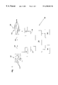
- FIG. 1 is a simplified diagram illustrating a merge/demerge tool for assembling or disassembling disc drives.
- FIG. 2 is a simplified block diagram showing a controller of the tool shown in FIG. 1 coupled to modular input and output boards.
- FIG. 3 is a more detailed top plan view showing a header board coupled to a modular input board and a modular output board.
- FIG. 1 an apparatus 100 for use in assembling (or disassembling) a disc stack 102 with an actuator assembly 104 is shown in a simplified block diagram.
- Disc stack or pack 102 includes a plurality of individual discs 106 carried on a spindle 108 .
- Actuator assembly 104 includes a plurality of actuator arms 110 which carry transducing heads (not shown) on their distal ends.
- the disc stack 102 and actuator assembly 104 are moved together as indicated by arrows 105 and the transducers are delicately positioned on the appropriate disc surfaces.
- the disc stack 102 itself can be assembled, the elements can be coupled or decoupled to/from motors such as spindle motors or voice coils for the actuator mechanism.
- the casing or other components can also be manipulated.
- Apparatus 100 includes a control system 120 which couples to sensors 122 and actuators 124 .
- Control system 120 also provides an output on output device 126 which may comprise, for example, a display and receive input through input device 128 .
- Input device 128 can be, for example, a manual input for use by an operator or a network or computer input for receiving digital commands.
- control system 120 causes the merge (or demerging) of disc stack 102 and actuator assembly 104 using actuators 124 which are controlled by actuator output 130 .
- Actuators 124 can include a device which can be controlled by control system 120 including display devices. The position and movement of components of disc stack 102 and actuator assembly 104 are sensed using sensors 124 and provided to control system 120 using sensor input 132 . This allows control system 120 to act as a controller based upon feedback from sensors 122 when controlling actuators 124 .
- Sensors 122 and actuators 124 can be any type of sensors or actuation device known or developed in the art which is used in a merge/demerge tool.
- FIG. 2 is a simplified diagram of control system 120 showing controller 150 coupled to a modular input/output board 152 through a data bus 154 in accordance with one embodiment of the present invention.
- Controller 150 typically includes a microprocessor or other device for controlling operation of the actuators 124 in response to the sensors 122 illustrated in FIG. 1 .
- Modular input/output board 152 includes a header board 160 which couples to controller 150 through bus 154 .
- Modular input/output board 152 also includes a modular output board 162 and a modular input board 164 which couple to header board 160 through bus 166 .
- modular output board 162 couples to actuators 124 and modular input board 164 couples to sensors 122 .
- a plurality of output boards 162 and input boards 164 can couple to header board 160 through bus 166 .
- a total of six input boards 164 or output boards 162 can couple to a single header board 160 .
- Header board 160 couples data bus 166 with data bus 154 such that controller 150 can send commands to individual actuators and receive data from individual sensors.
- each output board 162 can provide a total of eight different outputs to eight different actuators and each input board 164 can receive a total of eight sensor inputs from eight sensors.
- the modularity offered by the embodiment of input/output board 152 set forth in FIG. 2 offers both size reduction and design efficiency in comparison with prior art control systems used in merge/demerge tools. Using the embodiment set forth in FIG. 2, only the desired number of input boards 164 and output boards 162 need to be provided and coupled to the header board 160 . This allows the control system 120 to be smaller than in comparable prior art designs and allows greater design flexibility for changing the configuration of the merge/demerge apparatus 100 to be modified to function with different types of disc drive systems.
- FIG. 3 is a top plan view of header board 160 , output board 162 and input board 164 shown assembled together.
- Header board 160 includes bus connection 200 which is configured to couple to bus 154 for communication with controller 150 shown in FIG. 2 .
- Header board 160 also includes bus connections 202 , 204 , 206 , 208 , 210 and 212 which are used for coupling in input boards 164 or output boards 162 .
- Header board 160 can, therefore, support a total of six input or output boards.
- Boards 160 , 162 and 164 can be secured together using any appropriate technique, such as track which holds boards 160 , 162 and 164 .
- Input board 164 includes bus connection 214 for coupling, for example, to bus connection 202 of header board 160 through bus 166 shown in FIG. 2 .
- Input board 164 includes sensor input plugs 216 , 218 , 220 , 222 , 224 , 226 , 228 and 230 for coupling to a total of eight sensors 122 through sensor inputs 132 shown in FIG. 1 .
- Each sensor plug 216 - 230 includes two sensor input connections 232 and 234 and a sensor power connection 236 .
- a light emitting diode (LED) or other display device 246 , 248 , 250 , 252 , 254 , 256 , 258 and 260 is associated with each sensor input 216 - 230 , respectively.
- LEDs 246 - 260 are used for diagnostic purposes to indicate the receipt of data.
- the power output 236 from each sensor input plug 216 - 230 can be used to power those types of sensors which require an external power source for their operation.
- Output board 162 includes bus connection 280 for coupling to, for example, bus connection 204 of header board 160 through bus 166 shown in FIG. 2 .
- Output board 160 includes a total of eight output plugs 282 , 284 , 286 , 288 , 290 , 292 , 294 and 296 .
- Each output plug 282 - 296 includes output terminals 298 and 300 for coupling to actuators 124 shown in FIG. 1 through actuator outputs 130 .
- eight LED or other display devices 302 , 304 , 306 , 308 , 310 , 312 , 314 and 316 are associated with each respective output plug connection 282 - 296 and can be used for diagnostic purposes.
- FIG. 3 only shows two modular boards, one input board 164 and one output board 162 , additional modular boards can be configured to couple to header board 160 .
- a total of six modular boards can be coupled to bus connections 202 - 212 of header board 160 . This configuration allows a total of 48 total input and/or output connections to be supported by a single header board 160 .
- the configuration provided with the present invention provides for a relatively small input/output board assembly with relatively inexpensive modular boards.
- the output board 162 are capable of driving actuators requiring relatively large currents, for example 2 amps direct current (DC) or 1 amp alternating current (AC), using commonly available driver chips.
- a solid state power relay available from International Rectifier, part number PVG 612 is used to drive the output.
- each modular board has dimensions of 1.125′′ ⁇ 4.25′′ ⁇ 0.5′′ and typically requires less than half of the total size required in prior art designs.
- Each input and output uses a single removable connection with makes connection fast, simple and reliable.
- the header board 160 can be modified for use with different types of controllers 150 .
- the modular boards 162 and 164 do not require reconfiguration for each type of controller. Instead, the header board 160 handles the interface between the controller 150 and the modular boards 162 and 164 . This allows cost reduction because only a single input board 164 and output board 162 need be designed and can be reused for other configurations. Additionally, the header boards 160 can be designed to function with a bus 154 which is either serial or parallel. In one configuration, input board 164 is configured to receive either AC or DC inputs ranging between 0 volts and 60 volts. In one embodiment, opto-isolators are used to isolate the input signals from the other electronics. Such opto-isolators are available from NEC Corporation, part number P52505-1-NEC. Various sensors inputs through plugs 216 - 230 can receive either AC or DC sensor inputs.
- the automated assembly system includes an assembly controller 150 configured to receive a plurality of sensor inputs and provide a plurality of controller outputs.
- the modular input/output board 152 includes at least one modular input board 164 configured to receive sensor inputs from the assembly system. Further, the modular input/output board 152 includes at least one modular output board 162 configured to drive components of the assembly system.
- the header board 160 of the modular input/output board 152 is configured to transfer input signals from the modular input board to the controller and to transfer controller outputs from the controller 150 to the modular output board 162 .
- the header board 160 includes a plurality of bus connections 202 - 212 configured to couple to the modular boards.
- the input and output boards include bus connections 214 , 280 configured to couple to the header board 160 through a bus 166 .
- the modular input board 164 includes at least one sensor plug 216 - 230 configured to couple to a sensor and receive sensor inputs.
- a power output is configured for each of the sensor inputs to provide power to each of the sensors.
- LEDs 246 - 260 and 302 - 316 are configured to provide diagnostic information for the input and output boards.
- the output board 162 includes at least one output plug 282 - 296 configured to drive components of the assembly system.
- the inputs to the modular input board 164 can access both AC and DC signals ranging between 0 and about 60 volts. Further, inputs from either NPN or PNP transistor type sensors can be received.
- the output board is configured to provide outputs of up to 2 amps DC and 1 amp AC.
Abstract
Description
Claims (19)
Priority Applications (2)
| Application Number | Priority Date | Filing Date | Title |
|---|---|---|---|
| US09/409,755 US6505083B1 (en) | 1999-05-07 | 1999-09-30 | Apparatus for assembling a disc storage system including a modular input/output board |
| SG200002326A SG109421A1 (en) | 1999-05-07 | 2000-04-19 | Apparatus for assembling a disc storage system including a modular input/output board |
Applications Claiming Priority (2)
| Application Number | Priority Date | Filing Date | Title |
|---|---|---|---|
| US13302199P | 1999-05-07 | 1999-05-07 | |
| US09/409,755 US6505083B1 (en) | 1999-05-07 | 1999-09-30 | Apparatus for assembling a disc storage system including a modular input/output board |
Publications (1)
| Publication Number | Publication Date |
|---|---|
| US6505083B1 true US6505083B1 (en) | 2003-01-07 |
Family
ID=26830963
Family Applications (1)
| Application Number | Title | Priority Date | Filing Date |
|---|---|---|---|
| US09/409,755 Expired - Fee Related US6505083B1 (en) | 1999-05-07 | 1999-09-30 | Apparatus for assembling a disc storage system including a modular input/output board |
Country Status (2)
| Country | Link |
|---|---|
| US (1) | US6505083B1 (en) |
| SG (1) | SG109421A1 (en) |
Citations (23)
| Publication number | Priority date | Publication date | Assignee | Title |
|---|---|---|---|---|
| US3471822A (en) | 1967-07-26 | 1969-10-07 | Amp Inc | Terminal junction system for electrical conductors |
| US3984873A (en) | 1974-09-16 | 1976-10-05 | Information Storage Systems, Inc. | Head loading and unloading assembly for a magnetic disc drive having a rotary actuator |
| US4005485A (en) | 1973-08-31 | 1977-01-25 | Xerox Corporation | Apparatus and method for loading and unloading transducer heads |
| US4504927A (en) | 1982-09-08 | 1985-03-12 | Allen-Bradley Company | Programmable controller with expandable I/O interface circuitry |
| US4738632A (en) * | 1986-02-06 | 1988-04-19 | Siemens Aktiengesellschaft | Electrical assembly with modular carriers for signal processing modules |
| US4771374A (en) * | 1982-06-04 | 1988-09-13 | Michel Ropelato | Modular device for controlling industrial processes |
| US4790762A (en) | 1985-07-23 | 1988-12-13 | Honeywell Inc. | Backplane for a modularly expandable programmable controller |
| US4851943A (en) | 1986-06-27 | 1989-07-25 | Maxtor | Disk drive assembly tool |
| US4862584A (en) | 1988-08-01 | 1989-09-05 | Rigidyne Corporation | Disk drive assembly station |
| US5012570A (en) | 1989-05-01 | 1991-05-07 | Ambac Automation Corp. | Method for robot assembly of computer hard disc onto a spindle |
| US5150512A (en) | 1989-03-15 | 1992-09-29 | International Business Machines Corporation | Method of assembling a disk file |
| US5181582A (en) | 1991-11-19 | 1993-01-26 | Meadows Merman R | Scaffold for an a-frame ladder |
| US5182798A (en) * | 1988-12-30 | 1993-01-26 | Pitney Bowes Inc. | Multiple material processing system start-up |
| US5265325A (en) | 1991-10-21 | 1993-11-30 | Areal Technology | Tooling for assembly of compact disk drive |
| US5465467A (en) | 1993-07-09 | 1995-11-14 | Fan; Sheng-Chi | Method of making chemical fiber knitted towelling |
| US5471733A (en) | 1992-06-26 | 1995-12-05 | Quantum Corporation | Process of assembling a disk drive with minimum spacing between disks |
| US5692289A (en) | 1994-06-10 | 1997-12-02 | Hitachi, Ltd. | Method of assembling a magnetic disk drive and a system therefor |
| US5737190A (en) | 1995-08-30 | 1998-04-07 | Frick York International | Digital input/output circuit board |
| US5785537A (en) | 1996-06-26 | 1998-07-28 | Robinson Nugent, Inc. | Electrical connector interlocking apparatus |
| US5802389A (en) * | 1994-12-29 | 1998-09-01 | Siemens Energy & Automation, Inc. | Expansion module address method and apparatus for a programmable logic controller |
| US5826325A (en) | 1997-07-10 | 1998-10-27 | International Business Machines Corporation | Method of merging heads |
| US5876240A (en) | 1997-04-01 | 1999-03-02 | The Whitaker Corp | Stacked electrical connector with visual indicators |
| US5991528A (en) * | 1997-11-05 | 1999-11-23 | Reliance Electric Industrial Company | Expert manufacturing system |
Family Cites Families (3)
| Publication number | Priority date | Publication date | Assignee | Title |
|---|---|---|---|---|
| US4882671A (en) * | 1985-06-05 | 1989-11-21 | Plus Development Corporation | Microprocessor controlled rigid disk file subsystem |
| KR100246511B1 (en) * | 1991-09-11 | 2000-03-15 | 토마스 에프. 멀베니 | 1.8" winchester drive card |
| WO1993010531A1 (en) * | 1991-11-22 | 1993-05-27 | Conner Peripherals, Inc. | Small size constant torque voice coil motor |
-
1999
- 1999-09-30 US US09/409,755 patent/US6505083B1/en not_active Expired - Fee Related
-
2000
- 2000-04-19 SG SG200002326A patent/SG109421A1/en unknown
Patent Citations (24)
| Publication number | Priority date | Publication date | Assignee | Title |
|---|---|---|---|---|
| US3471822A (en) | 1967-07-26 | 1969-10-07 | Amp Inc | Terminal junction system for electrical conductors |
| US4005485A (en) | 1973-08-31 | 1977-01-25 | Xerox Corporation | Apparatus and method for loading and unloading transducer heads |
| US3984873A (en) | 1974-09-16 | 1976-10-05 | Information Storage Systems, Inc. | Head loading and unloading assembly for a magnetic disc drive having a rotary actuator |
| US4771374A (en) * | 1982-06-04 | 1988-09-13 | Michel Ropelato | Modular device for controlling industrial processes |
| US4916600A (en) * | 1982-06-04 | 1990-04-10 | Michell Ropelato | Modular device for controlling industrial processes |
| US4504927A (en) | 1982-09-08 | 1985-03-12 | Allen-Bradley Company | Programmable controller with expandable I/O interface circuitry |
| US4790762A (en) | 1985-07-23 | 1988-12-13 | Honeywell Inc. | Backplane for a modularly expandable programmable controller |
| US4738632A (en) * | 1986-02-06 | 1988-04-19 | Siemens Aktiengesellschaft | Electrical assembly with modular carriers for signal processing modules |
| US4851943A (en) | 1986-06-27 | 1989-07-25 | Maxtor | Disk drive assembly tool |
| US4862584A (en) | 1988-08-01 | 1989-09-05 | Rigidyne Corporation | Disk drive assembly station |
| US5182798A (en) * | 1988-12-30 | 1993-01-26 | Pitney Bowes Inc. | Multiple material processing system start-up |
| US5150512A (en) | 1989-03-15 | 1992-09-29 | International Business Machines Corporation | Method of assembling a disk file |
| US5012570A (en) | 1989-05-01 | 1991-05-07 | Ambac Automation Corp. | Method for robot assembly of computer hard disc onto a spindle |
| US5265325A (en) | 1991-10-21 | 1993-11-30 | Areal Technology | Tooling for assembly of compact disk drive |
| US5181582A (en) | 1991-11-19 | 1993-01-26 | Meadows Merman R | Scaffold for an a-frame ladder |
| US5471733A (en) | 1992-06-26 | 1995-12-05 | Quantum Corporation | Process of assembling a disk drive with minimum spacing between disks |
| US5465467A (en) | 1993-07-09 | 1995-11-14 | Fan; Sheng-Chi | Method of making chemical fiber knitted towelling |
| US5692289A (en) | 1994-06-10 | 1997-12-02 | Hitachi, Ltd. | Method of assembling a magnetic disk drive and a system therefor |
| US5802389A (en) * | 1994-12-29 | 1998-09-01 | Siemens Energy & Automation, Inc. | Expansion module address method and apparatus for a programmable logic controller |
| US5737190A (en) | 1995-08-30 | 1998-04-07 | Frick York International | Digital input/output circuit board |
| US5785537A (en) | 1996-06-26 | 1998-07-28 | Robinson Nugent, Inc. | Electrical connector interlocking apparatus |
| US5876240A (en) | 1997-04-01 | 1999-03-02 | The Whitaker Corp | Stacked electrical connector with visual indicators |
| US5826325A (en) | 1997-07-10 | 1998-10-27 | International Business Machines Corporation | Method of merging heads |
| US5991528A (en) * | 1997-11-05 | 1999-11-23 | Reliance Electric Industrial Company | Expert manufacturing system |
Also Published As
| Publication number | Publication date |
|---|---|
| SG109421A1 (en) | 2005-03-30 |
Similar Documents
| Publication | Publication Date | Title |
|---|---|---|
| TWI448067B (en) | Control method for multiaxial driver, multiaxial driver, and multiaxial control system comprising the driver | |
| CA1328002C (en) | Power transmission | |
| US7196488B2 (en) | Motor driving apparatus | |
| EP0794483A3 (en) | Recording apparatus | |
| SE406659B (en) | STORAGE SYSTEM | |
| US20030235060A1 (en) | Motor driving controller | |
| JPH0253325B2 (en) | ||
| US6505083B1 (en) | Apparatus for assembling a disc storage system including a modular input/output board | |
| JP2003518311A (en) | Connection system between cartridge and library using transfer robot on rail system | |
| US6085975A (en) | Barcode module for an automated data storage library | |
| WO2003005041A2 (en) | A test handling apparatus and method | |
| US6697214B2 (en) | Removable disk drive with separable electrical and mechanical components | |
| US7038418B2 (en) | Numerical control apparatus | |
| US20070198773A1 (en) | Data storage drive for automated data storage library | |
| WO1988008158A1 (en) | Robot controller | |
| US10395691B1 (en) | Device configured to switch a test system channel between multiple drive controllers | |
| CN102402489B (en) | Electronic device and control method for electronic device | |
| EP0012264A1 (en) | Data transducing apparatus | |
| JPH05154778A (en) | Manipulator | |
| US7136988B2 (en) | Mass data storage library frame spanning for mixed media | |
| US6427318B1 (en) | Universal smart merge/demerge tool | |
| US5850569A (en) | Method for integrating a module into a storage library | |
| JP2011019354A (en) | Motor control apparatus | |
| JPH05138466A (en) | Service device | |
| JPH06267238A (en) | Flexible disk device |
Legal Events
| Date | Code | Title | Description |
|---|---|---|---|
| AS | Assignment |
Owner name: SEAGATE TECHNOLOGY, INC., CALIFORNIA Free format text: ASSIGNMENT OF ASSIGNORS INTEREST;ASSIGNORS:PFEIFFER, MICHAEL W.;JOHNSON, ERIC D.;REEL/FRAME:010306/0183 Effective date: 19990929 |
|
| AS | Assignment |
Owner name: SEAGATE TECHNOLOGY LLC, CALIFORNIA Free format text: ASSIGNMENT OF ASSIGNORS INTEREST;ASSIGNOR:SEAGATE TECHNOLOGY, INC.;REEL/FRAME:010988/0465 Effective date: 20000628 |
|
| AS | Assignment |
Owner name: JPMORGAN CHASE BANK, AS COLLATERAL AGENT, NEW YORK Free format text: SECURITY AGREEMENT;ASSIGNOR:SEAGATE TECHNOLOGY LLC;REEL/FRAME:013177/0001 Effective date: 20020513 Owner name: JPMORGAN CHASE BANK, AS COLLATERAL AGENT,NEW YORK Free format text: SECURITY AGREEMENT;ASSIGNOR:SEAGATE TECHNOLOGY LLC;REEL/FRAME:013177/0001 Effective date: 20020513 |
|
| FEPP | Fee payment procedure |
Free format text: PAYOR NUMBER ASSIGNED (ORIGINAL EVENT CODE: ASPN); ENTITY STATUS OF PATENT OWNER: LARGE ENTITY |
|
| AS | Assignment |
Owner name: SEAGATE TECHNOLOGY LLC, CALIFORNIA Free format text: RELEASE OF SECURITY INTERESTS IN PATENT RIGHTS;ASSIGNOR:JPMORGAN CHASE BANK, N.A. (FORMERLY KNOWN AS THE CHASE MANHATTAN BANK AND JPMORGAN CHASE BANK), AS ADMINISTRATIVE AGENT;REEL/FRAME:016958/0340 Effective date: 20051130 |
|
| FPAY | Fee payment |
Year of fee payment: 4 |
|
| SULP | Surcharge for late payment | ||
| AS | Assignment |
Owner name: JPMORGAN CHASE BANK, N.A., AS ADMINISTRATIVE AGENT Free format text: SECURITY AGREEMENT;ASSIGNORS:MAXTOR CORPORATION;SEAGATE TECHNOLOGY LLC;SEAGATE TECHNOLOGY INTERNATIONAL;REEL/FRAME:022757/0017 Effective date: 20090507 Owner name: WELLS FARGO BANK, NATIONAL ASSOCIATION, AS COLLATE Free format text: SECURITY AGREEMENT;ASSIGNORS:MAXTOR CORPORATION;SEAGATE TECHNOLOGY LLC;SEAGATE TECHNOLOGY INTERNATIONAL;REEL/FRAME:022757/0017 Effective date: 20090507 |
|
| FPAY | Fee payment |
Year of fee payment: 8 |
|
| AS | Assignment |
Owner name: SEAGATE TECHNOLOGY HDD HOLDINGS, CALIFORNIA Free format text: RELEASE;ASSIGNOR:JPMORGAN CHASE BANK, N.A., AS ADMINISTRATIVE AGENT;REEL/FRAME:025662/0001 Effective date: 20110114 Owner name: SEAGATE TECHNOLOGY LLC, CALIFORNIA Free format text: RELEASE;ASSIGNOR:JPMORGAN CHASE BANK, N.A., AS ADMINISTRATIVE AGENT;REEL/FRAME:025662/0001 Effective date: 20110114 Owner name: MAXTOR CORPORATION, CALIFORNIA Free format text: RELEASE;ASSIGNOR:JPMORGAN CHASE BANK, N.A., AS ADMINISTRATIVE AGENT;REEL/FRAME:025662/0001 Effective date: 20110114 Owner name: SEAGATE TECHNOLOGY INTERNATIONAL, CALIFORNIA Free format text: RELEASE;ASSIGNOR:JPMORGAN CHASE BANK, N.A., AS ADMINISTRATIVE AGENT;REEL/FRAME:025662/0001 Effective date: 20110114 |
|
| AS | Assignment |
Owner name: THE BANK OF NOVA SCOTIA, AS ADMINISTRATIVE AGENT, Free format text: SECURITY AGREEMENT;ASSIGNOR:SEAGATE TECHNOLOGY LLC;REEL/FRAME:026010/0350 Effective date: 20110118 |
|
| AS | Assignment |
Owner name: SEAGATE TECHNOLOGY INTERNATIONAL, CAYMAN ISLANDS Free format text: TERMINATION AND RELEASE OF SECURITY INTEREST IN PATENT RIGHTS;ASSIGNOR:WELLS FARGO BANK, NATIONAL ASSOCIATION, AS COLLATERAL AGENT AND SECOND PRIORITY REPRESENTATIVE;REEL/FRAME:030833/0001 Effective date: 20130312 Owner name: EVAULT INC. (F/K/A I365 INC.), CALIFORNIA Free format text: TERMINATION AND RELEASE OF SECURITY INTEREST IN PATENT RIGHTS;ASSIGNOR:WELLS FARGO BANK, NATIONAL ASSOCIATION, AS COLLATERAL AGENT AND SECOND PRIORITY REPRESENTATIVE;REEL/FRAME:030833/0001 Effective date: 20130312 Owner name: SEAGATE TECHNOLOGY US HOLDINGS, INC., CALIFORNIA Free format text: TERMINATION AND RELEASE OF SECURITY INTEREST IN PATENT RIGHTS;ASSIGNOR:WELLS FARGO BANK, NATIONAL ASSOCIATION, AS COLLATERAL AGENT AND SECOND PRIORITY REPRESENTATIVE;REEL/FRAME:030833/0001 Effective date: 20130312 Owner name: SEAGATE TECHNOLOGY LLC, CALIFORNIA Free format text: TERMINATION AND RELEASE OF SECURITY INTEREST IN PATENT RIGHTS;ASSIGNOR:WELLS FARGO BANK, NATIONAL ASSOCIATION, AS COLLATERAL AGENT AND SECOND PRIORITY REPRESENTATIVE;REEL/FRAME:030833/0001 Effective date: 20130312 |
|
| REMI | Maintenance fee reminder mailed | ||
| LAPS | Lapse for failure to pay maintenance fees | ||
| STCH | Information on status: patent discontinuation |
Free format text: PATENT EXPIRED DUE TO NONPAYMENT OF MAINTENANCE FEES UNDER 37 CFR 1.362 |
|
| FP | Lapsed due to failure to pay maintenance fee |
Effective date: 20150107 |