US6505382B1 - Hinge apparatus with cam mechanism - Google Patents
Hinge apparatus with cam mechanism Download PDFInfo
- Publication number
- US6505382B1 US6505382B1 US09/387,276 US38727699A US6505382B1 US 6505382 B1 US6505382 B1 US 6505382B1 US 38727699 A US38727699 A US 38727699A US 6505382 B1 US6505382 B1 US 6505382B1
- Authority
- US
- United States
- Prior art keywords
- cam
- assembly
- hinge
- display screen
- base
- Prior art date
- Legal status (The legal status is an assumption and is not a legal conclusion. Google has not performed a legal analysis and makes no representation as to the accuracy of the status listed.)
- Expired - Lifetime
Links
Images


Classifications
-
- G—PHYSICS
- G06—COMPUTING; CALCULATING OR COUNTING
- G06F—ELECTRIC DIGITAL DATA PROCESSING
- G06F1/00—Details not covered by groups G06F3/00 - G06F13/00 and G06F21/00
- G06F1/16—Constructional details or arrangements
- G06F1/1613—Constructional details or arrangements for portable computers
- G06F1/1633—Constructional details or arrangements of portable computers not specific to the type of enclosures covered by groups G06F1/1615 - G06F1/1626
- G06F1/1675—Miscellaneous details related to the relative movement between the different enclosures or enclosure parts
- G06F1/1681—Details related solely to hinges
-
- G—PHYSICS
- G06—COMPUTING; CALCULATING OR COUNTING
- G06F—ELECTRIC DIGITAL DATA PROCESSING
- G06F1/00—Details not covered by groups G06F3/00 - G06F13/00 and G06F21/00
- G06F1/16—Constructional details or arrangements
- G06F1/1613—Constructional details or arrangements for portable computers
- G06F1/1615—Constructional details or arrangements for portable computers with several enclosures having relative motions, each enclosure supporting at least one I/O or computing function
- G06F1/1616—Constructional details or arrangements for portable computers with several enclosures having relative motions, each enclosure supporting at least one I/O or computing function with folding flat displays, e.g. laptop computers or notebooks having a clamshell configuration, with body parts pivoting to an open position around an axis parallel to the plane they define in closed position
-
- G—PHYSICS
- G06—COMPUTING; CALCULATING OR COUNTING
- G06F—ELECTRIC DIGITAL DATA PROCESSING
- G06F1/00—Details not covered by groups G06F3/00 - G06F13/00 and G06F21/00
- G06F1/16—Constructional details or arrangements
- G06F1/1613—Constructional details or arrangements for portable computers
- G06F1/1633—Constructional details or arrangements of portable computers not specific to the type of enclosures covered by groups G06F1/1615 - G06F1/1626
- G06F1/1675—Miscellaneous details related to the relative movement between the different enclosures or enclosure parts
- G06F1/1679—Miscellaneous details related to the relative movement between the different enclosures or enclosure parts for locking or maintaining the movable parts of the enclosure in a fixed position, e.g. latching mechanism at the edge of the display in a laptop or for the screen protective cover of a PDA
-
- E—FIXED CONSTRUCTIONS
- E05—LOCKS; KEYS; WINDOW OR DOOR FITTINGS; SAFES
- E05D—HINGES OR SUSPENSION DEVICES FOR DOORS, WINDOWS OR WINGS
- E05D11/00—Additional features or accessories of hinges
- E05D11/10—Devices for preventing movement between relatively-movable hinge parts
- E05D11/1014—Devices for preventing movement between relatively-movable hinge parts for maintaining the hinge in only one position, e.g. closed
-
- E—FIXED CONSTRUCTIONS
- E05—LOCKS; KEYS; WINDOW OR DOOR FITTINGS; SAFES
- E05D—HINGES OR SUSPENSION DEVICES FOR DOORS, WINDOWS OR WINGS
- E05D11/00—Additional features or accessories of hinges
- E05D11/10—Devices for preventing movement between relatively-movable hinge parts
- E05D11/1028—Devices for preventing movement between relatively-movable hinge parts for maintaining the hinge in two or more positions, e.g. intermediate or fully open
- E05D11/105—Devices for preventing movement between relatively-movable hinge parts for maintaining the hinge in two or more positions, e.g. intermediate or fully open the maintaining means acting perpendicularly to the pivot axis
-
- E—FIXED CONSTRUCTIONS
- E05—LOCKS; KEYS; WINDOW OR DOOR FITTINGS; SAFES
- E05F—DEVICES FOR MOVING WINGS INTO OPEN OR CLOSED POSITION; CHECKS FOR WINGS; WING FITTINGS NOT OTHERWISE PROVIDED FOR, CONCERNED WITH THE FUNCTIONING OF THE WING
- E05F1/00—Closers or openers for wings, not otherwise provided for in this subclass
- E05F1/08—Closers or openers for wings, not otherwise provided for in this subclass spring-actuated, e.g. for horizontally sliding wings
- E05F1/10—Closers or openers for wings, not otherwise provided for in this subclass spring-actuated, e.g. for horizontally sliding wings for swinging wings, e.g. counterbalance
- E05F1/12—Mechanisms in the shape of hinges or pivots, operated by springs
- E05F1/1207—Mechanisms in the shape of hinges or pivots, operated by springs with a coil spring parallel with the pivot axis
- E05F1/1215—Mechanisms in the shape of hinges or pivots, operated by springs with a coil spring parallel with the pivot axis with a canted-coil torsion spring
-
- E—FIXED CONSTRUCTIONS
- E05—LOCKS; KEYS; WINDOW OR DOOR FITTINGS; SAFES
- E05Y—INDEXING SCHEME RELATING TO HINGES OR OTHER SUSPENSION DEVICES FOR DOORS, WINDOWS OR WINGS AND DEVICES FOR MOVING WINGS INTO OPEN OR CLOSED POSITION, CHECKS FOR WINGS AND WING FITTINGS NOT OTHERWISE PROVIDED FOR, CONCERNED WITH THE FUNCTIONING OF THE WING
- E05Y2900/00—Application of doors, windows, wings or fittings thereof
- E05Y2900/60—Application of doors, windows, wings or fittings thereof for other use
- E05Y2900/606—Application of doors, windows, wings or fittings thereof for other use for electronic devices
Definitions
- the present invention relates generally to hinge mechanisms. More particularly, the present invention relates to a hinge mechanism which is suitable for use in a portable computing device.
- FIG. 1 is a diagrammatic representation of a portable computer or, more specifically, a notebook computer 102 .
- notebook computer 102 includes a rotating, or hinging, section 106 and a fixed section 110 .
- Rotating section 106 typically includes a display screen 114
- fixed section 110 often includes input/output devices such as a keyboard 118 and a track pad 119 , in addition to buttons 121 which are associated with track pad 119 .
- Fixed section 110 also houses a central processing unit and other computer hardware (not shown).
- Hinges 122 are used to allow rotating section 106 to rotate with respect to fixed section 110 , and are effectively positioned to couple a top surface of fixed section 110 to a front surface of rotating section 106 .
- hinges 122 hold a front edge of rotating section 106 in close proximity to a top edge of fixed section 110 .
- rotating section 106 is “open” at roughly a 90 degree angle measured with respect to fixed section 110 .
- the configuration of hinges 122 may be such that rotating section 106 is constrained to rotation within a certain range. Once the angle between fixed section 110 and rotating section 106 is as desired, then rotating section 106 may at least be temporarily fixed with respect to fixed section 110 .
- hinges 122 In order for rotating section 106 to be able to rotate and to hold a desired position at a given angle of rotation, hinges 122 typically include, or are associated with, brakes.
- the brakes which are typically either spring-based or gear-based, are used to effectively “lock” hinges 122 in place. Hinges 122 are locked into place to prevent rotation when no torque, or rotational force, is applied to hinges 122 or, more generally, to either rotating section 106 or fixed section 110 .
- notebook computer 102 When notebook computer 102 is closed, i.e., when rotating section 106 is flush with fixed section 110 such that display screen 114 is effectively adjacent keyboard 118 , notebook computer 102 also includes a latching mechanism 126 that holds notebook computer 102 in a closed position.
- Latching mechanism 126 includes an activator 126 a , a linker 126 b , and a receiver 126 c .
- Linker 126 b engages receiver 126 c when notebook computer 102 is closed such that rotating section 106 is locked with respect to fixed section 110 .
- Activator 126 a is coupled to linker 126 b , and is used to disengage linker 126 b from receiver 126 c when rotating section 106 is to be unlocked from fixed section 110 .
- a receptacle rather than a linker, may be coupled to an activator. It should be appreciated that some notebook computers may include more than one linker and more than one receptacle.
- Latching mechanism 126 is generally required by notebook computer 102 in order to enhance the portability of notebook computer 102 . Without latching mechanism 126 , it would be difficult to hold rotating section 106 closed against fixed section 110 , as rotating section 106 would generally be free to rotate into an open position with respect to fixed section 110 . If rotating section 106 were to open with respect to fixed section 110 at an inopportune time, e.g., when notebook computer 102 is packed for transport, damage to notebook computer 102 may occur. For example, display screen 114 or keyboard 118 may be damaged from contact with relatively heavy objects. The latching mechanism also makes carrying of the notebook computer significantly less difficult by keeping the rotating section 106 fixed with respect to the fixed section 110 .
- latching mechanism 126 may be relatively complex, as linker 126 b must be arranged to be received and engaged within receptacle 126 c . Hence, the tolerances associated with the manufacture and positioning of linker 126 b and receiver 126 c must enable linker 126 b and receiver 126 c to interface. The positioning of linker 126 b with respect to receiver 125 c is crucial to ensure that notebook computer 102 may be properly closed and locked.
- the present invention relates to an improved hinge mechanism for use with a portable computing device.
- One aspect of the present invention relates to a hinge apparatus which provides a cam action to obtain latching functionality.
- Another aspect of the present invention pertains to a display screen of a portable computing device that is rotateably-hinged to a base such that the display screen is set back from the base when the display screen is opened.
- a hinge mechanism in one embodiment, includes a first assembly with a connection pivot and a cam follower, and a second assembly with a cam.
- the first and second assemblies are rotationally coupled to the connection pivot, and the cam follower cooperates with the cam to produce a moment about the connection pivot to hold the first assembly with respect to the second assembly when the second assembly is in a first position (i.e., closed position) with respect to the first assembly.
- a hinge assembly which includes such latching, or locking, functionality (by holding the first assembly with respect to the second assembly) generally eliminates the need for a separate latching mechanism when the hinge assembly is used with a portable computing apparatus.
- a computing apparatus in still another embodiment, includes a first housing which contains a processor, a display screen, and a first hinge mechanism that couples the display screen to the first housing.
- the display screen rotates with respect to the first housing, and the first hinge mechanism is capable of holding the display screen substantially against the first housing when the display screen is positioned such that a front surface of the display screen is substantially parallel to a top surface of the first housing.
- the computing arrangement includes a handle that is coupled to the first hinge mechanism.
- a computing apparatus a base, a display screen, and a hinge arranged to rotateably couple the display screen to the base.
- the display screen is arranged to rotate with respect to the base, and the display screen has an open position and a closed position with respect to the base. When the display screen is in the open position, a bottom edge of the display screen is set back a distance from a back surface of the base.
- FIG. 1 is a diagrammatic representation of a notebook computer
- FIG. 2 is a diagrammatic side-view representation of positions of a hinging mechanism which is suitable for biasing a display section of a portable computing apparatus against a base section of the portable computing apparatus in accordance with an embodiment of the present invention
- FIG. 3 is a diagrammatic perspective representation of a hinging mechanism in a closed position in accordance with an embodiment of the present invention
- FIG. 4 is a diagrammatic perspective representation of a hinging mechanism in an open position in accordance with an embodiment of the present invention
- FIG. 5 is a diagrammatic exploded representation of the pieces associated with a hinging mechanism in accordance with an embodiment of the present invention
- FIG. 6 a is a diagrammatic representation of a hinge base in accordance with an embodiment of the present invention.
- FIG. 6 b is a diagrammatic representation of a cam arm in accordance with an embodiment of the present invention.
- FIG. 6 c is a diagrammatic representation of a cam in accordance with an embodiment of the present invention.
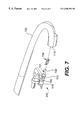
- FIG. 7 is a diagrammatic representation of a portion of a handle which is suitable for attaching to a hinge base of a hinge mechanism in accordance with another embodiment of the present invention.
- FIGS. 8 a and 8 b are diagrams illustrating a notebook computer having a lid connected to a base by a rotateable hinge.
- Portable computing devices typically include a mechanical latch which is arranged to lock a lid of the device against a base of the device for storage.
- the construction and the positioning of a latch may be complicated, as a section of the latch that is coupled to the lid must be positioned to engage a section of the latch that is coupled to the base when the lid is to be locked to the base. That is, the tolerances associated with the manufacture and the positioning of parts of the latch must enable the parts to interface. Since tolerances associated with coupling a lid to a base using hinges add to the tolerances associated with a latch, there is generally very little room for error in the positioning of the parts of the latch.
- the invention relates to a hinge which includes the ability to serve as a latch and thus allows a dedicated latch mechanism to be eliminated from a portable computing device.
- a user of the portable computing device need not be concerned with having to manipulate a dedicated latch mechanism.
- the inventive hinge is also relatively easy to manufacture.
- Such a hinge is arranged such that when the angle between a lid of a portable computing device and a base of the portable computing device is in a particular range, no torque is required to essentially “close” the lid onto the base. When the lid is closed with respect to the base, the lid is effectively latched to the base, and will not “open” without the application of a torque.
- the invention relates to a portable computing device that has a display screen rotateably-hinged to a base.
- the display screen When the display screen is opened, such as for use by a user, the display screen is set back from the base.
- the resulting portable computing device thus presents the user with a open and spacious feel.
- FIG. 2 shows three positions of a lid hinge assembly with respect to a base hinge assembly.
- a portable computing system typically includes two hinges which rotateably couple a lid of the computing system to a base of the computing system.
- the hinges are often positioned such that one hinge is placed to the right of the center of the computing system, while the second hinge is placed to the left of the center of the computing system.
- a hinge mechanism 204 is arranged for use to the right of the center of the computing system, although it should be appreciated that hinge mechanism 204 may be modified for use to the left of the center of the computing system.
- Hinge mechanism 204 includes a lid hinge assembly 210 that is rotateably coupled to a base hinge assembly 216 .
- the coupling enables lid hinge assembly 210 to rotate with respect to base hinge assembly 216 while base hinge assembly 216 remains in a substantially fixed position.
- a bracket 218 , or a frame, of lid hinge assembly 210 is arranged to be attached to the lid, e.g., the display, of a portable computing apparatus such as a notebook computer.
- the attachment may occur through the use of fasteners, e.g., screws.
- base hinge assembly 216 is arranged to be fastened, or otherwise attached, to the base of a notebook computer.
- the various parts included with hinge mechanism 204 may be formed from a variety of different materials. Suitable materials may include, but are not limited to, plastics, aluminum, and steel. Further, the parts may be manufactured using substantially any suitable processes including, by way of example, milling processes, molding processes, and extrusion processes.
- FIG. 3 is a diagrammatic perspective representation of a hinging mechanism, i.e., hinging mechanism 204 of FIG. 2, in accordance with an embodiment of the present invention.
- Hinging mechanism 204 is shown in a “closed” or, more specifically, a locked position.
- hinging mechanism 204 is arranged such that a lid of a notebook computer, which is coupled to lid hinge assembly 210 , is substantially closed against the base of the notebook computer, which is coupled to base hinge assembly 216 .
- a closed position in one embodiment, implies that the surface of a display screen of the notebook computer is held substantially flush against the surface of a keyboard of the base of the notebook computer.
- Base hinge assembly 216 which will be described below with reference to FIGS. 5 and 6 a , includes a hinge base or base hinge piece 312 which is mounted to the base of a notebook computer.
- base plate 314 of base hinge piece 312 is fastened to a base of a notebook computer.
- Base hinge piece 312 also includes a shaft 316 around which a cam arm 324 may be rotateably positioned.
- Cam arm 324 supports a cam follower 326 which cooperates with a cam 332 .
- Cam arm 324 will be discussed below with respect to FIGS. 5 and 6 b .
- Cam 332 which is a part of lid hinge assembly 210 , is mounted with respect to lid hinge assembly 210 such that cam 332 is essentially constrained to move with a hinge connection 336 , as will be described in more detail below with respect to FIGS. 5 and 6 c .
- Cam 332 is in contact with cam follower 326 of cam arm 324 when an angle of opening associated with lid hinge assembly 210 is in a particular range.
- the cam 332 contacts the cam follower 326 and an external torque is needed to be induced to rotate the lid hinge assembly 210 to further reduce the angle of opening.
- the cam 332 passes over the cam follower 326 .
- the cam 332 will have passed over the cam follower 326 and once then occurs the cam arm 324 and the cam follower 326 produce a torque (or moment) on the lid hinge assembly 210 to cause the angle of opening to further be reduced to a closed position.
- the lid hinge assembly 210 is closed to a certain extent, then further closed with an external torque, and then “pulled” into the closed position without any external torque.
- the cam follower 326 begins to push against the cam 332 to put the lid hinge assembly 210 in the closed position when the angle of opening is in a particular range (e.g., typically about 5-10 degrees from the closed position).
- the closed position can also be considered a locked position.
- the torque applied by the cam arm 324 and the cam follower 326 acts to effectively latch or lock the lid hinge assembly 210 in the closed position. This torque also generally prevents accidental unlocking from occurring.
- hinging mechanism 204 is in a closed position, cam 332 of lid hinge assembly 210 is positioned against a cam follower 326 such that cam 332 may not move with respect to cam follower 326 without the application of an appropriate torque to either bracket 218 or an arm 304 of lid hinge assembly 210 .
- no latch mechanism is needed, and the lid hinge assembly 210 is able to be again opened by that application of an external torque that exceeds the torque applied by the cam arm 324 and the cam follower 326 .
- the external torque needed to open the lid hinge assembly 210 from the closed position exceeds a predetermined level which is determined dependent on the weight of the lid.
- the external torque is on the order of 6-9 in.lbs. in order to open the lid hinge assembly 210 .
- cam spring 323 is a pre-loaded, coiled, constant force spring that is positioned around shaft 316 .
- cam spring 323 is effectively arranged to maintain the locked position (i.e., closed position) until an appropriate hinge torque is applied to unlock hinge mechanism 204 .
- Hinge connection 336 e.g., a torque master hinge, of lid hinge assembly 210 is coupled to base hinge assembly 216 such that hinge connection 336 may rotate about a secondary axis of hinge mechanism 204 .
- Hinge connection 336 rotates about the secondary axis of hinge mechanism 204 such that the opening of lid hinge assembly 210 with respect to base hinge assembly 216 may be controlled. That is, a hinge torque associated with hinge connection 336 effectively controls the angle at which lid hinge assembly 210 is opened, i.e., the angle of opening, as measure with respect to base hinge assembly 216 .
- Hinge connection 336 is also arranged to substantially maintain the angle of opening when the angle of opening is greater than a predetermined angle.
- the predetermined angle may vary widely depending upon the requirements of a particular design.
- the predetermined angle may be approximately ten degrees as measured between the bottom surface of base hinge assembly 216 and a bottom surface of frame 218 , i.e., the surface of frame 218 which faces base hinge assembly 216 when the angle of opening is below approximately ten degrees.
- cam spring 323 , cam arm 324 , cam follower 326 , and cam 332 are arranged to bias lid hinge assembly 210 closed with respect to base hinge assembly 216 .
- the hinge torque is approximately zero.
- Hinge mechanism 204 is arranged such that hinge connection 336 , which is associated with a pivot point of lid hinge assembly 210 , may be located towards the back of a notebook computer of which hinge mechanism 204 is a part.
- the axis of rotation associated with hinge connection 336 is slightly lowered as compared to the axis of rotation associated with shaft 316 .
- the positioning of hinge connection 336 (and, hence, the pivot point or axis which passes axially through hinge connection 336 ) at the back of a notebook computer and lowered below the top surface of the fixed section (e.g., base) of the notebook computer enables a lid (display screen) coupled to frame 218 to open away from a base of the notebook computer.
- the distance by which the lid is opened away (or set back) from the base of the notebook computer is determined by the length of the lid hinge assembly 210 from the frame 218 to the hinge connection 336 . Allowing a screen to open away from a base such that there is a substantial clearance between the bottom of the screen and the base and thus provides a user with a more spacious impression of the notebook computer as the screen is set back from the base. This aspect of the invention is discussed further below with reference to FIGS. 8 a and 8 b .
- cam 332 When hinge mechanism 204 is in a closed position, cam 332 is in contact with cam follower 326 . However, when hinge mechanism 204 is in an open position such that the angle of opening is greater than the range of approximately 5-15 degrees, cam 332 is not in contact with cam follower 326 .
- FIG. 4 is a diagrammatic perspective representation of a hinge mechanism in an open configuration in accordance with an embodiment of the present invention.
- a hinge mechanism 404 is substantially the same as hinge mechanism 204 of FIG. 2 .
- hinge mechanism 204 is adapted for use as a “right-side” hinge mechanism with respect to a notebook computer
- hinge mechanism 404 is adapted for use as a “left-side” hinge mechanism.
- hinge mechanism 404 may be considered to be a “mirror image” of hinge mechanism 204 .
- hinge mechanism 404 occurs as a hinge connection 436 rotates around a hinge band (or a torque master hinge rotates around or a torque master band) (not shown). Friction between hinge connection 436 and the hinge band prevents hinge connection 436 from slipping significantly when no torque is applied to either a lid hinge assembly 410 or a base hinge assembly 416 . In other words, friction allows a lid coupled to a frame 418 to remain open to a desired angle.
- hinge mechanism 404 when hinge mechanism 404 is in an open position, e.g., with an angle of opening of approximately 90 degrees, a cam 432 typically does not come into contact with a cam follower 426 .
- the maximum angle of opening for a hinge mechanism 404 may be widely varied, in one embodiment, the maximum angle of opening is approximately in the range of 160-180 degrees.
- Cam 432 moves closer to contacting cam follower 426 , and eventually contacts cam follower 426 as the angle of opening is decreased, thereby creating a moment about a hinge axis. Once the angle of opening is decreased to below approximately ten degrees, cam 432 and cam follower 426 cooperate with a cam spring 423 and a cam arm 424 , as mentioned above with respect to FIG. 3, to close and to lock hinge mechanism 404 .
- Base hinge piece 312 which is shown in more detail in FIG. 6 a , includes a base plate 314 which is arranged to be secured to a base portion of a notebook computer, e.g., through a screw.
- a cantilever shaft 316 protrudes from base hinge piece 312 , and is arranged to extend through a cam arm 324 such that cam arm 324 may rotate around cantilever shaft 316 .
- An axis which runs axially through cantilever shaft 316 defines an axis of rotation for cam arm 324 , which may be formed from a material such as aluminum.
- Base hinge piece 312 further includes a coupler 518 which, in the described embodiment, is arranged to be coupled to a handle, as will be discussed below with reference to FIG. 7 .
- Coupler 518 defines an opening (not shown) into which a linkage associated with a handle may be press-fit.
- An extension 520 which extends from base plate 514 , is arranged to facilitate the coupling of band 522 to base plate 314 .
- Band 522 provides a surface over which hinge connection 336 may be rotateably mounted.
- band 522 may be formed from any suitable material, in one embodiment, band 522 may be formed from a metal such as steel and titanium.
- a protrusion 540 which is located proximally to shaft 316 of base hinge piece 312 engages an end of a preloaded cam spring 323 when cam spring 323 is coiled over shaft 316 .
- a first end of cam spring 323 which may be formed from coiled steel, may be attached to protrusion 540 in a variety of different methods, in one embodiment, cam spring 323 is held against the protrusion 540 through a hook provided in the protrusion 540 and a spring-force.
- Cam arm 324 which is shown in more detail in FIG. 6 b , includes a protrusion 548 which is arranged to engage a second end of cam spring 323 . As cam arm 524 is rotated, cam spring 323 may either extend or retract, depending upon the direction in which cam arm 524 rotates.
- a cam follower 326 is sized to be placed at least partially within cam arm 324 such that it may be held within cam arm 324 by a cam pin 544 inserted through a cam arm opening 546 .
- the cam follower 326 is a roller that can rotate about the cam pin 544 (such as when being contacted by the cam 332 ).
- Cam pin 544 may take on a variety of different configurations. Such configurations include, but are not limited to, a flat-headed pin and a Tinnerman retainer, as will be appreciated by those skilled in the art.
- Lid hinge assembly 210 includes a frame 218 which is typically attached to a lid of a notebook computer, a hinge connection 336 , and a cam 332 . While hinge connection 336 , which may be formed from a material such as plastic, is arranged to rotate over band 522 , cam 332 , which may be formed from a material such as steel, is arranged to cooperate with cam follower 326 , cam arm 324 , and cam spring 323 to effectively latch, e.g., lock, lid hinge assembly 210 with respect to base hinge assembly 216 .
- cam 332 is formed from steel, and includes an opening 560 through which a shaft (not shown) associated with lid hinge assembly 210 may pass.
- a shaft may include an extension which effectively constrains cam 332 from becoming decoupled from lid hinge assembly 210 .
- opening 560 may be sized to fit over a portion of hinge connection 336 .
- a base hinge assembly may include a coupler 518 that is adapted for coupling to a handle.
- FIG. 7 is a diagrammatic representation of a portion of a handle which is suitable for attaching to a base hinge assembly in accordance with a second embodiment of the present invention.
- a portion of a handle 700 which is arranged to extend effectively between two hinge assemblies associated with a notebook computer, is rotateably coupled to a base hinge plate 312 , which was described above with respect to FIGS. 5 and 6 a .
- Handle 700 may be used to facilitate the transport of a notebook computer.
- an extension 518 of base hinge plate 312 is coupled, e.g., attached, to handle 700 through a pin 701 .
- a first end 703 of pin 701 may be press-fit into an opening 705 in extension 518 .
- a second end 702 of pin 701 which may be a shaft, is sized to pass through a compression spring 704 and into an opening (not shown) at a first end 710 of handle 700 .
- Spring 704 is used to bias the handle 700 back to its “down” position after being pulled “up” for use.
- handle 700 has been shown as having a substantially circular cross-section, the shape of handle 700 may vary.
- the substantially circular cross-section enables handle 700 to be readily gripped.
- Other cross-sectional shapes which may be relatively easy to grip include, but are not limited to, an ovular cross-sectional shape and polygonal cross-sectional shape.
- handle 700 may be formed from a variety of different materials. The materials are generally strong, durable, and relatively lightweight. By way of example, a rubber material may be used to form handle 700 .
- FIG. 8 a is a diagram illustrating a notebook computer 800 having a lid 802 connected to a base 804 by a rotateable hinge 806 .
- the rotateable hinge 806 is, for example, the hinge mechanism 204 discussed above or other suitable hinges.
- Th e rotateable hinge 806 includes an extension arm 808 that extends the lid 802 back from the base 804 by a distance D when in the open position as shown in FIG. 8 a .
- the distance D by which the lid 802 is opened away (or set back) from the base 804 of the notebook computer 800 is determined by the length of the lid hinge assembly 210 from the hinge connection 336 to the frame 218 . More particularly, when the lid 802 is in the open position, a bottom edge 810 of the lid 802 is set back a distance D from a back surface 812 of the base 804 .
- the advantageous lid position provided by this aspect of the invention can be seen by comparing FIG. 8 a with FIG. 1 . Allowing a lid (or screen display) to open away from a base in this manner provides a user with a more spacious impression of the notebook computer, as the screen is set back from the base.
- FIG. 8 b illustrates the notebook computer 800 in a closed position.
- the rotateable hinge 806 enables the lid 802 to rotate about the rotateable hinge 806 and the extension arm 808 is adjacent to the back surface of the base 804 in the closed position.
- rotateable hinge 806 can couple to the base below the top surface of the base.
- the rotateable hinge 806 couples to the base 804 at a position within a bottom half of the base 804 .
- the rotateable hinge 806 is coupled to the base 804 near the center of the base 804 or lower.
- the lower the rotateable hinge 806 is coupled to the base 804 the greater the distance D that is obtained to set back the lid 802 from the base 804 when the lid 802 is in the open position.
- a latching hinge mechanism has been described as being suitable for use in a notebook computing device.
- the hinge mechanism may be used a variety of other devices as well. Such devices may include, but are not limited to, notepad computers, personal electronic organizers, and calculators.
- the torque associated with opening a latched hinge assembly may vary depending upon the requirements of a particular design. For example, the torque necessary to effectively unlock, or open, a locked hinge assembly may be increased if the hinge assembly is designed for use with a computing device which is intended to be transported frequently.
- the torque associated with rotating a hinge connection over a hinge band is chosen such that the weight of a computer screen of the computing device may be supported for an angle of rotation of approximately 160 degrees.
- the torque is also selected to be low enough to prevent the base of the computing device from lifting off of a flat surface while the lid of the device is in the process of being opened.
- the materials used to form or fabricate the various parts associated with a hinge mechanism may be widely varied.
- the materials which are typically chosen are strong, durable materials which may withstand a relatively high level of wear and tear.
- many parts may be formed from plastic.
- a cam has generally been described as being fabricated from steel, if the weight of the cam is of particular concern, in one embodiment, the cam may instead be formed from a plastic material.
- a portable computing apparatus typically includes more than one hinge mechanism.
- both hinge mechanisms may be the latching hinge mechanisms of the present invention. It should be understood, however, that for some notebook computers that include two hinge mechanisms, only one of the hinge mechanisms may be a latching hinge mechanism.
- a notebook computer with two hinge mechanisms may include only one latching hinge mechanism when the latching hinge mechanism is strong enough to lock the notebook computer by itself.
- the design of the components of a latching hinge mechanism may vary without departing from the spirit or the scope of the present invention.
- the design of the overall cam mechanism which includes the cam, the cam arm, the cam follower, the cam pin, and the cam spring, may vary.
- the shape of the cam may be ovular. Therefore, the above-described examples or embodiments are to be considered as illustrative and not restrictive, and the invention is not to be limited to the details given herein, but may be modified within the scope of the appended claims.
Abstract
Description
Claims (43)
Priority Applications (1)
| Application Number | Priority Date | Filing Date | Title |
|---|---|---|---|
| US09/387,276 US6505382B1 (en) | 1999-05-14 | 1999-08-31 | Hinge apparatus with cam mechanism |
Applications Claiming Priority (2)
| Application Number | Priority Date | Filing Date | Title |
|---|---|---|---|
| US13412199P | 1999-05-14 | 1999-05-14 | |
| US09/387,276 US6505382B1 (en) | 1999-05-14 | 1999-08-31 | Hinge apparatus with cam mechanism |
Publications (1)
| Publication Number | Publication Date |
|---|---|
| US6505382B1 true US6505382B1 (en) | 2003-01-14 |
Family
ID=26831988
Family Applications (1)
| Application Number | Title | Priority Date | Filing Date |
|---|---|---|---|
| US09/387,276 Expired - Lifetime US6505382B1 (en) | 1999-05-14 | 1999-08-31 | Hinge apparatus with cam mechanism |
Country Status (1)
| Country | Link |
|---|---|
| US (1) | US6505382B1 (en) |
Cited By (30)
| Publication number | Priority date | Publication date | Assignee | Title |
|---|---|---|---|---|
| US20030067416A1 (en) * | 2000-03-15 | 2003-04-10 | Kim Yongjoon | Computer having plural monitors |
| WO2003107574A2 (en) * | 2002-06-13 | 2003-12-24 | Motorola Inc. | Electronics devices with spring biased hinges and methods therefor |
| US20040140410A1 (en) * | 2003-01-16 | 2004-07-22 | Dui-Ming Tsai | Support apparatus for balancing the connecting gap between a LCD module and a computer mainframe |
| US20040184228A1 (en) * | 2003-01-29 | 2004-09-23 | Kabushiki Kaisha Toshiba | Electronic apparatus with latch mechanism to fix housings overlaid and connected by hinges |
| US6899311B1 (en) | 2003-01-22 | 2005-05-31 | Apple Computer, Inc. | Easel display arrangement |
| US20050138775A1 (en) * | 2003-12-31 | 2005-06-30 | Oakley Nicholas W. | Mobile computer compound hinge |
| US20060010649A1 (en) * | 2004-07-17 | 2006-01-19 | Hon Hai Precision Industry Co., Ltd. | Hinge assembly for media player |
| US20060168890A1 (en) * | 2005-01-14 | 2006-08-03 | Samsung Electronics Co., Ltd. | Refrigerator |
| US20070011848A1 (en) * | 2005-07-13 | 2007-01-18 | Lu Sheng-Nan | Pivot device |
| US20070152113A1 (en) * | 2005-12-30 | 2007-07-05 | Okuley James M | Compressed workspace notebook computer |
| US20110069431A1 (en) * | 2009-09-18 | 2011-03-24 | Li-Hau Hu | Rotating Shaft Structure for Screen and Foldable Portable Electronic Device |
| US20120099249A1 (en) * | 2010-10-21 | 2012-04-26 | Fih (Hong Kong) Limited | Hinge assembly for foldable electronic device |
| KR101209317B1 (en) | 2004-06-30 | 2012-12-06 | 엘지전자 주식회사 | A hinge assembly and portable computer having the same |
| US20130322011A1 (en) * | 2012-06-04 | 2013-12-05 | Pegatron Corporation | Docking station and portable apparatus |
| US9625954B2 (en) | 2014-11-26 | 2017-04-18 | Microsoft Technology Licensing, Llc | Multi-pivot hinge |
| US9625953B2 (en) | 2014-11-11 | 2017-04-18 | Microsoft Technology Licensing, Llc | Covered multi-pivot hinge |
| US20170311464A1 (en) | 2016-04-26 | 2017-10-26 | Microsoft Technology Licensing, Llc | Structural device cover |
| US9851759B2 (en) | 2014-12-31 | 2017-12-26 | Microsoft Technology Licensing, Llc | Multi-pivot hinge cover |
| US9910465B2 (en) | 2014-11-11 | 2018-03-06 | Microsoft Technology Licensing, Llc | Covered radius hinge |
| US9936593B2 (en) | 2016-04-14 | 2018-04-03 | Microsoft Technology Licensing, Llc | Device with a rotatable display |
| US10159158B2 (en) | 2016-04-14 | 2018-12-18 | Microsoft Technology Licensing, Llc | Device with a rotatable display |
| US10162389B2 (en) | 2015-09-25 | 2018-12-25 | Microsoft Technology Licensing, Llc | Covered multi-axis hinge |
| US10172248B1 (en) | 2016-04-14 | 2019-01-01 | Microsoft Technology Licensing, Llc | Device with a rotatable display |
| US10174534B2 (en) | 2015-01-27 | 2019-01-08 | Microsoft Technology Licensing, Llc | Multi-pivot hinge |
| US10345851B2 (en) | 2016-04-14 | 2019-07-09 | Microsoft Technology Licensing, Llc | Device with a rotatable display |
| US10437293B2 (en) | 2016-09-23 | 2019-10-08 | Microsoft Technology Licensing, Llc | Multi-axis hinge |
| US10514730B2 (en) | 2015-10-29 | 2019-12-24 | Hewlett-Packard Development Company, L.P. | Hinge including a lock |
| US10754391B2 (en) | 2016-08-08 | 2020-08-25 | Microsoft Technology Licensing, Llc | Axial cam hinge |
| US10996710B2 (en) | 2016-04-14 | 2021-05-04 | Microsoft Technology Licensing, Llc | Device with a rotatable display |
| JP2022128825A (en) * | 2021-02-24 | 2022-09-05 | レノボ・シンガポール・プライベート・リミテッド | Electronic apparatus |
Citations (18)
| Publication number | Priority date | Publication date | Assignee | Title |
|---|---|---|---|---|
| US4584639A (en) | 1983-12-23 | 1986-04-22 | Key Logic, Inc. | Computer security system |
| US4692838A (en) | 1986-07-07 | 1987-09-08 | Emhart Industries, Inc. | Fire panel with door providing ease of service |
| US4897873A (en) * | 1988-11-04 | 1990-01-30 | Motorola, Inc. | Multipurpose hinge apparatus for foldable telephones |
| US5165145A (en) * | 1990-09-27 | 1992-11-24 | Smith Corona Corporation | Hinge for use with portable electronic apparatus |
| US5553305A (en) | 1992-04-14 | 1996-09-03 | International Business Machines Corporation | System for synchronizing execution by a processing element of threads within a process using a state indicator |
| US5555157A (en) * | 1994-03-02 | 1996-09-10 | Apple Computer, Inc. | Enclosure for electronic apparatus having a cover catch member engageable with two different housing catch members |
| US5619650A (en) | 1992-12-31 | 1997-04-08 | International Business Machines Corporation | Network processor for transforming a message transported from an I/O channel to a network by adding a message identifier and then converting the message |
| US5699698A (en) * | 1994-07-20 | 1997-12-23 | Aerospatiale Societe Nationale Industrielle | System for extending or retracting two members and cam-locking the members in the extended position |
| US5789828A (en) | 1996-12-24 | 1998-08-04 | Tremaine; Susan C. | Low voltage power supply and distribution center |
| US5793978A (en) | 1994-12-29 | 1998-08-11 | Cisco Technology, Inc. | System for routing packets by separating packets in to broadcast packets and non-broadcast packets and allocating a selected communication bandwidth to the broadcast packets |
| US5909540A (en) | 1996-11-22 | 1999-06-01 | Mangosoft Corporation | System and method for providing highly available data storage using globally addressable memory |
| US5915094A (en) | 1994-12-06 | 1999-06-22 | International Business Machines Corporation | Disk access method for delivering multimedia and video information on demand over wide area networks |
| US5918229A (en) | 1996-11-22 | 1999-06-29 | Mangosoft Corporation | Structured data storage using globally addressable memory |
| US5961584A (en) | 1994-12-09 | 1999-10-05 | Telefonaktiebolaget Lm Ericsson | System for managing internal execution threads |
| US6108868A (en) * | 1998-03-30 | 2000-08-29 | Lin; Davys | Positioning hinge having a cam block |
| US6148480A (en) * | 1998-02-06 | 2000-11-21 | Nec Corporation | Hinge construction with a snap-open, snap-shut feel, for a folding mobile phone handset |
| US6252767B1 (en) | 1999-06-22 | 2001-06-26 | Hewlett-Packard Company | Low impedance hinge for notebook computer |
| US6256129B1 (en) | 1997-03-28 | 2001-07-03 | Samsung Electronics Co., Ltd. | Portable computer and method of automatically controlling direction of infrared signal transmission and reception |
-
1999
- 1999-08-31 US US09/387,276 patent/US6505382B1/en not_active Expired - Lifetime
Patent Citations (18)
| Publication number | Priority date | Publication date | Assignee | Title |
|---|---|---|---|---|
| US4584639A (en) | 1983-12-23 | 1986-04-22 | Key Logic, Inc. | Computer security system |
| US4692838A (en) | 1986-07-07 | 1987-09-08 | Emhart Industries, Inc. | Fire panel with door providing ease of service |
| US4897873A (en) * | 1988-11-04 | 1990-01-30 | Motorola, Inc. | Multipurpose hinge apparatus for foldable telephones |
| US5165145A (en) * | 1990-09-27 | 1992-11-24 | Smith Corona Corporation | Hinge for use with portable electronic apparatus |
| US5553305A (en) | 1992-04-14 | 1996-09-03 | International Business Machines Corporation | System for synchronizing execution by a processing element of threads within a process using a state indicator |
| US5619650A (en) | 1992-12-31 | 1997-04-08 | International Business Machines Corporation | Network processor for transforming a message transported from an I/O channel to a network by adding a message identifier and then converting the message |
| US5555157A (en) * | 1994-03-02 | 1996-09-10 | Apple Computer, Inc. | Enclosure for electronic apparatus having a cover catch member engageable with two different housing catch members |
| US5699698A (en) * | 1994-07-20 | 1997-12-23 | Aerospatiale Societe Nationale Industrielle | System for extending or retracting two members and cam-locking the members in the extended position |
| US5915094A (en) | 1994-12-06 | 1999-06-22 | International Business Machines Corporation | Disk access method for delivering multimedia and video information on demand over wide area networks |
| US5961584A (en) | 1994-12-09 | 1999-10-05 | Telefonaktiebolaget Lm Ericsson | System for managing internal execution threads |
| US5793978A (en) | 1994-12-29 | 1998-08-11 | Cisco Technology, Inc. | System for routing packets by separating packets in to broadcast packets and non-broadcast packets and allocating a selected communication bandwidth to the broadcast packets |
| US5918229A (en) | 1996-11-22 | 1999-06-29 | Mangosoft Corporation | Structured data storage using globally addressable memory |
| US5909540A (en) | 1996-11-22 | 1999-06-01 | Mangosoft Corporation | System and method for providing highly available data storage using globally addressable memory |
| US5789828A (en) | 1996-12-24 | 1998-08-04 | Tremaine; Susan C. | Low voltage power supply and distribution center |
| US6256129B1 (en) | 1997-03-28 | 2001-07-03 | Samsung Electronics Co., Ltd. | Portable computer and method of automatically controlling direction of infrared signal transmission and reception |
| US6148480A (en) * | 1998-02-06 | 2000-11-21 | Nec Corporation | Hinge construction with a snap-open, snap-shut feel, for a folding mobile phone handset |
| US6108868A (en) * | 1998-03-30 | 2000-08-29 | Lin; Davys | Positioning hinge having a cam block |
| US6252767B1 (en) | 1999-06-22 | 2001-06-26 | Hewlett-Packard Company | Low impedance hinge for notebook computer |
Cited By (43)
| Publication number | Priority date | Publication date | Assignee | Title |
|---|---|---|---|---|
| US20030067416A1 (en) * | 2000-03-15 | 2003-04-10 | Kim Yongjoon | Computer having plural monitors |
| GB2405050B (en) * | 2002-06-13 | 2005-10-26 | Motorola Inc | Electronics devices with spring biased hinges and methods therefor |
| WO2003107574A2 (en) * | 2002-06-13 | 2003-12-24 | Motorola Inc. | Electronics devices with spring biased hinges and methods therefor |
| WO2003107574A3 (en) * | 2002-06-13 | 2004-07-29 | Motorola Inc | Electronics devices with spring biased hinges and methods therefor |
| US20040166890A1 (en) * | 2002-06-13 | 2004-08-26 | Ryszard Gordecki | Electronics devices with spring biased hinges and methods therefor |
| GB2405050A (en) * | 2002-06-13 | 2005-02-16 | Motorola Inc | Electronics devices with spring biased hinges and methods therefor |
| US7111362B2 (en) * | 2002-06-13 | 2006-09-26 | Motorola, Inc. | Electronics devices with spring biased hinges and methods therefor |
| US20040140410A1 (en) * | 2003-01-16 | 2004-07-22 | Dui-Ming Tsai | Support apparatus for balancing the connecting gap between a LCD module and a computer mainframe |
| US6796542B2 (en) * | 2003-01-16 | 2004-09-28 | Quanta Computer Inc. | Support apparatus for balancing the connecting gap between a LCD module and a computer mainframe |
| US6899311B1 (en) | 2003-01-22 | 2005-05-31 | Apple Computer, Inc. | Easel display arrangement |
| US20040184228A1 (en) * | 2003-01-29 | 2004-09-23 | Kabushiki Kaisha Toshiba | Electronic apparatus with latch mechanism to fix housings overlaid and connected by hinges |
| US20050138775A1 (en) * | 2003-12-31 | 2005-06-30 | Oakley Nicholas W. | Mobile computer compound hinge |
| KR101209317B1 (en) | 2004-06-30 | 2012-12-06 | 엘지전자 주식회사 | A hinge assembly and portable computer having the same |
| US20060010649A1 (en) * | 2004-07-17 | 2006-01-19 | Hon Hai Precision Industry Co., Ltd. | Hinge assembly for media player |
| US20060168890A1 (en) * | 2005-01-14 | 2006-08-03 | Samsung Electronics Co., Ltd. | Refrigerator |
| US20070011848A1 (en) * | 2005-07-13 | 2007-01-18 | Lu Sheng-Nan | Pivot device |
| US7275286B2 (en) * | 2005-07-13 | 2007-10-02 | Shin Zu Shing Co., Ltd. | Pivot device |
| US20070152113A1 (en) * | 2005-12-30 | 2007-07-05 | Okuley James M | Compressed workspace notebook computer |
| US8369085B2 (en) * | 2009-09-18 | 2013-02-05 | Acer Inc. | Rotating shaft structure for screen and foldable portable electronic device |
| US20110069431A1 (en) * | 2009-09-18 | 2011-03-24 | Li-Hau Hu | Rotating Shaft Structure for Screen and Foldable Portable Electronic Device |
| US8432677B2 (en) * | 2010-10-21 | 2013-04-30 | Shenzhen Futaihong Precision Industry Co., Ltd. | Hinge assembly for foldable electronic device |
| US20120099249A1 (en) * | 2010-10-21 | 2012-04-26 | Fih (Hong Kong) Limited | Hinge assembly for foldable electronic device |
| US20130322011A1 (en) * | 2012-06-04 | 2013-12-05 | Pegatron Corporation | Docking station and portable apparatus |
| US9152187B2 (en) * | 2012-06-04 | 2015-10-06 | Pegatron Corporation | Docking station and portable apparatus |
| US9625953B2 (en) | 2014-11-11 | 2017-04-18 | Microsoft Technology Licensing, Llc | Covered multi-pivot hinge |
| US9910465B2 (en) | 2014-11-11 | 2018-03-06 | Microsoft Technology Licensing, Llc | Covered radius hinge |
| US9625954B2 (en) | 2014-11-26 | 2017-04-18 | Microsoft Technology Licensing, Llc | Multi-pivot hinge |
| US10114424B2 (en) | 2014-11-26 | 2018-10-30 | Microsoft Technology Licensing, Llc | Multi-pivot hinge |
| US9851759B2 (en) | 2014-12-31 | 2017-12-26 | Microsoft Technology Licensing, Llc | Multi-pivot hinge cover |
| US10174534B2 (en) | 2015-01-27 | 2019-01-08 | Microsoft Technology Licensing, Llc | Multi-pivot hinge |
| US10162389B2 (en) | 2015-09-25 | 2018-12-25 | Microsoft Technology Licensing, Llc | Covered multi-axis hinge |
| US10514730B2 (en) | 2015-10-29 | 2019-12-24 | Hewlett-Packard Development Company, L.P. | Hinge including a lock |
| US10159158B2 (en) | 2016-04-14 | 2018-12-18 | Microsoft Technology Licensing, Llc | Device with a rotatable display |
| US10172248B1 (en) | 2016-04-14 | 2019-01-01 | Microsoft Technology Licensing, Llc | Device with a rotatable display |
| US9936593B2 (en) | 2016-04-14 | 2018-04-03 | Microsoft Technology Licensing, Llc | Device with a rotatable display |
| US10345851B2 (en) | 2016-04-14 | 2019-07-09 | Microsoft Technology Licensing, Llc | Device with a rotatable display |
| US10996710B2 (en) | 2016-04-14 | 2021-05-04 | Microsoft Technology Licensing, Llc | Device with a rotatable display |
| US20170311464A1 (en) | 2016-04-26 | 2017-10-26 | Microsoft Technology Licensing, Llc | Structural device cover |
| US10999944B2 (en) | 2016-04-26 | 2021-05-04 | Microsoft Technology Licensing, Llc | Structural device cover |
| US10754391B2 (en) | 2016-08-08 | 2020-08-25 | Microsoft Technology Licensing, Llc | Axial cam hinge |
| US10437293B2 (en) | 2016-09-23 | 2019-10-08 | Microsoft Technology Licensing, Llc | Multi-axis hinge |
| JP2022128825A (en) * | 2021-02-24 | 2022-09-05 | レノボ・シンガポール・プライベート・リミテッド | Electronic apparatus |
| US11775027B2 (en) | 2021-02-24 | 2023-10-03 | Lenovo (Singapore) Pte. Ltd. | Electronic apparatus |
Similar Documents
| Publication | Publication Date | Title |
|---|---|---|
| US6505382B1 (en) | Hinge apparatus with cam mechanism | |
| US6256194B1 (en) | Portable computer with latch assembly | |
| JP2500099B2 (en) | Structure with lid | |
| US8302261B2 (en) | Electronic device and hinge thereof | |
| EP1643059B1 (en) | Sliding latching mechanism | |
| US7050295B2 (en) | Bidirectional latch assembly and electronic apparatuses using the same | |
| US7669287B2 (en) | Hinge structure that allows adjustment of inclined angle of the load supported thereon | |
| US6507485B2 (en) | Spring loaded hinge apparatus | |
| US20060109637A1 (en) | Portable computer having improved latch mechanism | |
| US7484778B2 (en) | Portable computer having improved latch mechanism | |
| US20210238894A1 (en) | Clamp lock for portable electronic device | |
| US7471508B2 (en) | System and method for locking computer | |
| US20050138771A1 (en) | Hinge | |
| US20040125552A1 (en) | Hinge device and electric and electronic apparatuses employing the same | |
| GB2244512B (en) | Door latching mechanisms | |
| US5573287A (en) | Bilateral-type door locking handle assembly | |
| US20090241292A1 (en) | Hinge assembly and computer housing using the same | |
| US6890008B1 (en) | Interlocking device for an electronic apparatus | |
| US20100321882A1 (en) | Computing Device Locking Mechanisms | |
| TWM631233U (en) | Foldable electronic device | |
| JP4071179B2 (en) | HINGE DEVICE AND ELECTRONIC DEVICE USING HINGE DEVICE | |
| JPH07334265A (en) | Electronic equipment | |
| JPH0736569A (en) | Electronic equipment | |
| US20030227180A1 (en) | Dual function latch that can be opened using either an axial force directed aginst the latching apparatus normal to the door surface or using a rotational force against the latching apparatus parallel to the door surface | |
| JP3119790B2 (en) | Double door locking device |
Legal Events
| Date | Code | Title | Description |
|---|---|---|---|
| AS | Assignment |
Owner name: APPLE COMPUTER, INC., CALIFORNIA Free format text: ASSIGNMENT OF ASSIGNORS INTEREST;ASSIGNORS:LAM, LAWRENCE;STRINGER, CHRIS J.;RICCOMINI, ROY;AND OTHERS;REEL/FRAME:010218/0513;SIGNING DATES FROM 19990622 TO 19990827 |
|
| STCF | Information on status: patent grant |
Free format text: PATENTED CASE |
|
| FPAY | Fee payment |
Year of fee payment: 4 |
|
| AS | Assignment |
Owner name: APPLE INC.,CALIFORNIA Free format text: CHANGE OF NAME;ASSIGNOR:APPLE COMPUTER, INC.;REEL/FRAME:019000/0383 Effective date: 20070109 Owner name: APPLE INC., CALIFORNIA Free format text: CHANGE OF NAME;ASSIGNOR:APPLE COMPUTER, INC.;REEL/FRAME:019000/0383 Effective date: 20070109 |
|
| FPAY | Fee payment |
Year of fee payment: 8 |
|
| FPAY | Fee payment |
Year of fee payment: 12 |