US6507667B1 - Color digital imaging apparatus having a rule-based hue-shift processor - Google Patents
Color digital imaging apparatus having a rule-based hue-shift processor Download PDFInfo
- Publication number
- US6507667B1 US6507667B1 US09/473,984 US47398499A US6507667B1 US 6507667 B1 US6507667 B1 US 6507667B1 US 47398499 A US47398499 A US 47398499A US 6507667 B1 US6507667 B1 US 6507667B1
- Authority
- US
- United States
- Prior art keywords
- color
- hue
- shift
- image signals
- illumination
- Prior art date
- Legal status (The legal status is an assumption and is not a legal conclusion. Google has not performed a legal analysis and makes no representation as to the accuracy of the status listed.)
- Expired - Fee Related
Links
Images


Classifications
-
- H—ELECTRICITY
- H04—ELECTRIC COMMUNICATION TECHNIQUE
- H04N—PICTORIAL COMMUNICATION, e.g. TELEVISION
- H04N1/00—Scanning, transmission or reproduction of documents or the like, e.g. facsimile transmission; Details thereof
- H04N1/46—Colour picture communication systems
- H04N1/56—Processing of colour picture signals
- H04N1/60—Colour correction or control
- H04N1/6083—Colour correction or control controlled by factors external to the apparatus
- H04N1/6086—Colour correction or control controlled by factors external to the apparatus by scene illuminant, i.e. conditions at the time of picture capture, e.g. flash, optical filter used, evening, cloud, daylight, artificial lighting, white point measurement, colour temperature
-
- H—ELECTRICITY
- H04—ELECTRIC COMMUNICATION TECHNIQUE
- H04N—PICTORIAL COMMUNICATION, e.g. TELEVISION
- H04N1/00—Scanning, transmission or reproduction of documents or the like, e.g. facsimile transmission; Details thereof
- H04N1/46—Colour picture communication systems
- H04N1/56—Processing of colour picture signals
- H04N1/60—Colour correction or control
- H04N1/6075—Corrections to the hue
Definitions
- the present invention relates to a color digital imaging apparatus, especially to a color digital imaging apparatus having a rule-based hue-shift processor for after-shot recovery.
- the goal of good color reproduction is to choose a set of spectral characteristics for the color digital imaging device which is as close as possible to the spectral characteristics of the intended display device.
- the digital signals produced by the color sensor will be a function of the spectral characteristics of the light used to illuminate the scene. For example, if the color processing in a camera is designed to give good color reproduction in a daylight light source, unacceptable color reproduction may be obtained if the camera is used with, flash, or fluorescent illumination. This is due to the fact that the response measured by the color sensors is a function of the spectral power distribution of the light source as well as the spectral reflection of the objects in the scene, and the spectral responses of the sensors.
- a conventional technology uses a color-correction matrix in the pre-processing section of the color digital imaging device.
- the matrix coefficient is obtained from a color matching function.
- the color matching function is obtained via complicated numerical analysis of the images.
- Some conventional technology applies a color temperature detecting circuit in the pre-processing section for modifying the matrix coefficients for a primary color separator used to perform a color-correction operation for a color digital imaging device. Eventually, selecting the color-correction matrix coefficients can account for changes in illuminant color temperature and provide an output image with better color performance.
- the post-processing module are designed following the ICC (International Color Consortium) Profile Format Specification for defining the output format of colors and also recording the conversion profiles of the spectral characteristics of a particular light source. Accordingly, the RGB input profiles are established which will correct the spectral sensitivities of an input device for a connection space. Thereupon, the output profiles are used to convert the signals from the connection space to a format that is expected by an output device.
- ICC International Color Consortium
- the implementation for the conventional technology is very complicated. The manufacture cost is also very high.
- the user can manually select a correspondent light source at the time of taking pictures, or even in viewing the images displayed on the display device.
- the after-shot recovery function is performed by a rule-based hue-shift processor for generating a color correction parameter to adjust the hue of the captured image according to a correct light source selected at a computer system. Consequently, the quality of the output image can be further guaranteed even after shot.
- the color digital imaging apparatus is embodied with a light source selector for generating an illumination selecting signal selected by the user.
- the after-shot recovery function is implemented in a computer system. When downloading the captured image in a computer system, a color correction function is performed at the computer system.
- the color correction function is mainly performed by the following elements: hue-shift analyzer for performing hue analysis on the original color digital image signals and generating hue-shift parameters; a Rule-Based hue-shift processor for generating color correction parameters by triggering a set of predetermined rules in response to the illumination selecting signal and the hue-shift parameters; a color correction module for performing color correction on the original digital color image signals and generating corrected digital color image signals according to a color conversion function based on the color correction parameters; a memory for storing the hue-shift parameters and the corrected digital color image signals; and a display interface for transferring the corrected digital color image signals from the second memory means to a display device and displaying a dialog box for illumination condition selections.
- FIG. 1 is a functional block diagram showing the preferred embodiment of the present invention.
- FIG. 2 is a flowchart showing the color correction procedure according of the preferred embodiment of the present invention.
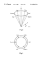
- FIG. 3 is a schematic diagram showing the HSI color model.
- FIG. 4 is a color plate showing the arrangement of the chromatic colors when converted from the HSI color model.
- the color digital imaging apparatus of the present invention can refer to a digital camera, a color video camera or a scanner.
- the present invention can be illustrated more clearly with reference to FIG. 1 .
- a light source selector 101 which provides various light sources for the user to select according to the illumination condition at the time of shooting, such as, sunny, cloudy, fluorescent lamp, and tungsten lamp.
- the light source selector 101 In response to a selected light source, the light source selector 101 generates an illumination selecting signal which is stored in a memory 106 .
- the color sensor 103 such as a CCD image sensor or a CMOS sensor, captures the image of the scene and generates original color image signals which are also stored in the memory 106 .
- the transmitting device 107 encodes the illumination selecting signal and the original color image signals in a format defined by a communication protocol of a connecting port, such as an USB, a serial port, or a parallel port. Then, the encoded image data will be transferred to the computer system 11 , or directly to a display device (not shown).
- the color correction function provided by the present invention is performed at the computer system.
- a receiving/decoding device 108 is provided for receiving and decoding the encoded original color image signals and the illumination selecting signal downloaded from the transmitting device 107 .
- the hue-shift analyzer 102 analyzes the hue of the original color image signals.
- the hue-shift analyzer 102 determines if the hue of the original color image signals shifts towards red, green or blue color based on the distribution of a color component on a histogram.
- the color monitor is based on LAB color model, color television based on YIQ color model, color printing based on CMY color model, etc.
- an HSI color model is adopted for analyzing hues.
- other color models can also be adopted too.
- HSI Human, Saturation, Intensity
- Hue for describing a pure color
- Saturation for giving a measure of the degree to which a pure color is diluted by white light
- Intensity for the measurement ranging from dark to white.
- the relationship among these three attributes can be illustrated from the chromaticity diagram as illustrated in FIG. 3 .
- H refers to the angle of the vector shown with respect to the vertical red axis.
- the angle of each of the six colors, i.e. Red, Yellow, Green, Cyanine, Blue and Magenta is 60 degrees.
- Saturation, S is proportional to the 1 ⁇ 2 radius distance away from the vertical axis.
- I is proportional to the distance away from the tip of the cone.
- the conic surface represents pure colors, its color is getting lighter when getting closer to the vertical axis.
- the vertical axis represents various hues. The luminosity increases as it getting farther from the tip of the cone.
- the hue shift analysis on the digital image signal begins from analyzing its luminosity channel (or gray level values ) based on the distribution diagram of the histogram.
- the mean value computed from the histogram is set as “0” which functions as a standard value for comparison.
- the difference indicates the degree of hue-shift.
- the difference with the largest value will be chosen as the hue-shift parameter. For instance, if the difference between the mean value of red color and the mean value of the luminosity channel is the largest.
- the hue of the image is tending to red.
- the red components of the image shall be reduced to a predetermined value according to a selected illumination condition.
- the hue-shift parameter shall be forwarded to the Rule-Based hue-shift processor 104 .
- Rule-Based hue-shift processor 104 is a Rule-Based system which is established according to an expert system.
- the Rule-Based hue-shift processor 104 can trigger a set of rules according to the hue-shift parameter input from hue-shift analyzer 102 and the illumination selecting signal input from the receiving/decoding device 108 .
- the set of rules can perform an inference procedure to generate a color correction parameter proper for a color transfer function. For instance, given several illumination conditions, including sunny, cloudy, fluorescent lamp, and tungsten lamp. Since the tungsten lamp contains more red components, and other illumination conditions contain relatively more blue components, therefore the magnitude of the blue components under these illumination conditions can be arranged in the order of fluorescent lamp>cloudy>sunny. Accordingly, the Rule-Base inference procedure can be simplified according to the selected illumination condition. For instance:
- Case 1 “sunny” is selected as an illumination condition: If the captured image contains more green components, then it indicates that the image was captured under fluorescent lamp. In another case, if the captured image contains more red components, then it indicates that the image was captured under tungsten lamp. On the other hand, if the green component or the red component in the captured image is normal, it indicates the color temperature is normal and thus it does not require the color correction procedure.
- Case 2 “Cloudy” is selected as an illumination condition: If the captured image contains more green components, then it indicates that the image was captured under fluorescent lamp. And if the captured image contains more red components, then it indicates that the image was captured under tungsten lamp. On the other hand, if the green components or the red components in the captured image are within a normal range, then it indicates that the color temperature of the image is normal and thus it does not require a color correction procedure.
- Case 4 “tungsten lamp” is selected as an illumination condition: If the captured image contains more blue components, then it indicates that the image was not captured under tungsten lamp. On the other hand, if the blue components contained in the captured image are within a normal range, it indicates that the color temperature of the image is normal and thus it does not require the color correction procedure.
- the Rule-Based Hue-Shift processor 104 may contain a set of predetermined rules for generating proper color correction parameters, such as a R_key, G_key, and B_key, for adjusting the hues of the RGB channels.
- the color correction parameters of the Rule-Based hue-shift processor 104 are sent to the color correction module 105 .
- FIG. 4 for illustrating the process for converting from HSI color model into RGB color values.
- the color plate as illustrated in FIG. 4 contains 7 colors.
- R_key refers to the link connecting the red color and Cyanine color.
- G_key refers to the link connecting green color and magenta color.
- B_key refers to the link connecting blue color and yellow color.
- R_key, G_key and B_key represents the values for adjusting color saturation.
- the colors at the opposite ends of each link represent the compensation hues.
- the key value for a hue represents the value for adjusting the saturation of that hue.
- the digital image signals are converted from the HSI color model to RGB colors.
- the color correction module 105 can compute the color correction parameters by computing the difference between the Hues and Saturation values of the original Red, Green Blue components and the Hues and Saturation values of the R_key, G_key, and B_key.
- the present invention only shows one method for introducing the color correction parameter into a color correction function. If the image contains more blue components, then the blue color value is adjusted to a predetermined value. For the convenience of operation, each time only one color is adjusted.
- the corrected digital image data, and the greatest hue-shift parameter along with its color are stored in a memory 109 .
- the display interface 110 reads the digital image data stored in the memory 109 .
- the display interface 110 also shows a dialog box for selecting an illumination condition.
- the dialog box contains various illumination conditions corresponding to the illumination conditions provided by the light source selector 101 . If the user founds that the color temperature of the displayed image was not right because a wrong illumination condition was accidentally selected. Then, the user can reset the illumination condition from the dialog box of the display interface 110 to reproduce the color in response to the newly selected illumination condition.
- the display device 110 sends the illumination correction signal to the hue-shift analyzer 102 .
- the hue-shift analyzer 102 reads the corrected digital image signals from the memory 109 and then performs the hue shift analysis on the corrected digital image signals.
- the hue-shift analyzer 102 , the Rule-Based hue-shift processor 104 and the color correction module 105 perform the same procedures as described above for adjusting the digital image signals stored in the memory 109 . Since the color correction procedure involves very little computation, so it can be done very quickly and allow the user to view the corrected image on the display device almost instantly. The loop continues until the user is satisfied with the color reproduction of the image on the display device.
- the color correction procedure can be illustrated in FIG. 2 .
- the computer system performs the following steps:
- Step 201 download the color digital image signals and the illumination selecting signal.
- the illumination selecting signals indicate illumination conditions such as, sunny, cloudy, fluorescent lamp, and tungsten lamp.
- Step 202 perform the hue-shift analysis on the color digital image signals.
- the hue shift analysis on the digital image signal begins from analyzing its luminosity channel (or gray levels ) based on the distribution diagram of the histogram.
- the mean value computed from the histogram is set as “0” which functions as a standard value for comparison.
- perform the same analysis for each red, green, blue channel of the image based on the distribution diagram of the histogram and compute the mean value of each channel.
- the difference indicates the degree of hue-shift.
- the difference with the largest value will be chosen as the hue-shift parameter.
- Step 203 Compute the hue-shift parameters for the red, green and blue channels.
- Ym represent the mean value for the gray level.
- Rm represents the mean value for the red channel.
- Gm represents the mean value for the green channel.
- Bm represents the mean value for the blue channel. Then, compute the hue-shift parameters for the red, green, and blue colors as follows:
- Step 204 Find the greatest hue-shift values from the absolute values among ⁇ R, ⁇ G, and ⁇ B.
- the greatest hue-shift value will be taken as the hue-shift parameter and then stored along with its color channel.
- Step 205 Determine if the hue-shift condition of the image corresponds to the original illumination condition? If yes, skip the image correction procedure and go to step 207 . If not, go to step 206 .
- Step 206 Determine if the hue-shift parameters of the red, green, and blue colors are within a default value? If yes, go to step 207 . If not, go to step 208 .
- Step 207 Store the image to be displayed on the display device.
- Step 208 Perform Rule-Based operations for outputting a proper color correction parameter, represented as R_key, G_key, or B_key.
- RGB channels are ranging from 0 to 255.
- the mean value of each R, G, or B channel is also ranging from 0 to 255.
- the difference between two mean values must be smaller than 255. If the absolute values of ⁇ R is the greatest among the rest, then the R_key can be converted to a value according to table 1:
- the rules in the Rule-Based system can be established by the exemplary rules as follows:
- Step 209 Perform color correction function according to the R_key, G_key or B_key found in step 208 .
- the color correction parameters can be introduced into the conversion function for converting from HSI color model into RGB values.
- the absolute value of R_key represents the saturation value of HSI model.
- the positive or negative values of the hues represent the increasing or decreasing of the hues. Accordingly, R_key ⁇ 0 means that the hue of Cyanine should be increased, and the hue of red color should be increased if otherwise.
- G_key ⁇ 0 it indicates that the hue of Magenta should be increased.
- G_key>0 the hue of green color should be increased.
- B_key ⁇ 0 indicates that the hue of yellow color should be increased.
- B_key>0 the hue of blue colors should be increased.
- step 202 In addition to the color correction, some other well-known image processing technology, such as interpolation, edge-enhancement, and Gamma correction can also be applied at this step. Then, go to step 202 .
- the color temperature of the image can be almost instantly displayed on the screen according to the selected illumination condition.
- the user can adjust the color reproduction of the image by simply clicking a illumination condition selected from the dialog box of the display interface.
- the color digital imaging apparatus of the present invention provides a light source selector for an easy operation, thereby to generate color images with high color fidelity without a color temperature detector.
- the color correction procedures described above do not require complicated image analysis and experiment.
- most color digital imaging devices provides many kinds of light sources, so they must follow complicated ICC profile formats for color corrections.
- the present invention can directly perform color corrections based on the Rule-Based hue-shift processor in response to a newly selected illumination condition, so the approach of the present invention is much easier to implement.
- the present invention can improve the effects of the color reproduction on the output image in a manner that does not require complicated computation and large memory space, so the manufacturing cost can be reduced.
- the Rule-Based hue-shift processor can also be implemented in fuzzy logic rules in a manner well-known to the art.
Abstract
Description
| TABLE 1 | |||||||||||
| ΔR | −255˜−129 | −128˜−65 | −64˜−33 | −32˜−17 | −16˜−1 | 0 | 1˜16 | 17˜32 | 33˜64 | 65˜128 | 129˜255 |
| R_key | 100 | 50 | 25 | 10 | 1 | 0 | −1 | −10 | −25 | −50 | −100 |
| TABLE 2 | |||||||||||
| ΔG | −255˜−129 | −128˜−65 | −64˜−33 | −32˜−17 | −16˜−1 | 0 | 1˜16 | 17˜32 | 33˜64 | 65˜128 | 129˜255 |
| G_key | 100 | 50 | 25 | 10 | 1 | 0 | −1 | −10 | −25 | −50 | −100 |
| TABLE 3 | |||||||||||
| ΔB | −255˜−129 | −128˜−65 | −64˜−33 | −32˜−17 | −16˜−1 | 0 | 1˜16 | 17˜32 | 33˜64 | 65˜128 | 129˜255 |
| B_key | 100 | 50 | 25 | 10 | 1 | 0 | −1 | −10 | −25 | −50 | −100 |
Claims (13)
Priority Applications (2)
| Application Number | Priority Date | Filing Date | Title |
|---|---|---|---|
| TW088120544A TW454424B (en) | 1999-11-24 | 1999-11-24 | Digital image reader with Rule-base color adjusting function |
| US09/473,984 US6507667B1 (en) | 1999-11-24 | 1999-12-29 | Color digital imaging apparatus having a rule-based hue-shift processor |
Applications Claiming Priority (2)
| Application Number | Priority Date | Filing Date | Title |
|---|---|---|---|
| TW088120544A TW454424B (en) | 1999-11-24 | 1999-11-24 | Digital image reader with Rule-base color adjusting function |
| US09/473,984 US6507667B1 (en) | 1999-11-24 | 1999-12-29 | Color digital imaging apparatus having a rule-based hue-shift processor |
Publications (1)
| Publication Number | Publication Date |
|---|---|
| US6507667B1 true US6507667B1 (en) | 2003-01-14 |
Family
ID=26666772
Family Applications (1)
| Application Number | Title | Priority Date | Filing Date |
|---|---|---|---|
| US09/473,984 Expired - Fee Related US6507667B1 (en) | 1999-11-24 | 1999-12-29 | Color digital imaging apparatus having a rule-based hue-shift processor |
Country Status (2)
| Country | Link |
|---|---|
| US (1) | US6507667B1 (en) |
| TW (1) | TW454424B (en) |
Cited By (13)
| Publication number | Priority date | Publication date | Assignee | Title |
|---|---|---|---|---|
| US20030184660A1 (en) * | 2002-04-02 | 2003-10-02 | Michael Skow | Automatic white balance for digital imaging |
| US6671001B2 (en) * | 2001-02-26 | 2003-12-30 | Mitac International Corp. | Offset level detection method for auto color gain control of analog video signals |
| US6674466B1 (en) * | 1998-05-21 | 2004-01-06 | Fuji Photo Film Co., Ltd. | Image processing apparatus utilizing light distribution characteristics of an electronic flash |
| US20050163392A1 (en) * | 2004-01-23 | 2005-07-28 | Old Dominion University | Color image characterization, enhancement and balancing process |
| WO2005074301A1 (en) * | 2004-01-30 | 2005-08-11 | Koninklijke Philips Electronics, N.V. | Enhancement of video images by boost of secondary colors |
| US20060001928A1 (en) * | 2004-06-25 | 2006-01-05 | Ikuo Hayaishi | Image data processing of color image |
| US7042602B1 (en) * | 1999-06-03 | 2006-05-09 | Nikon Corporation | Image correction apparatus and recording medium having image correction program |
| US20060245668A1 (en) * | 2005-04-29 | 2006-11-02 | Cazier Robert P | Method and apparatus for the creation of image post-processing parameter curves |
| US20070091185A1 (en) * | 2005-10-20 | 2007-04-26 | Samsung Electronics Co., Ltd. | Method and apparatus for color temperature correction in a built-in camera of a portable terminal |
| US20080069439A1 (en) * | 2006-09-18 | 2008-03-20 | Sumsung Electro-Mechanics Co., Ltd. | System, method and medium performing color correction of display images |
| CN102572448A (en) * | 2012-02-28 | 2012-07-11 | 王锦峰 | Device and method for shooting color image based on red, white and blue (RWB) three-color light |
| US11205369B2 (en) * | 2020-03-25 | 2021-12-21 | Beijing Xiaomi Mobile Software Co., Ltd. | Screen display method and apparatus, and method and apparatus for generating grayscale mapping information |
| US11393429B2 (en) * | 2020-02-24 | 2022-07-19 | Qisda Corporation | Display device and color adjusting method |
Citations (5)
| Publication number | Priority date | Publication date | Assignee | Title |
|---|---|---|---|---|
| US4847680A (en) * | 1986-09-24 | 1989-07-11 | Canon Kabushiki Kaisha | Image pickup apparatus with white balance control |
| US5812286A (en) * | 1995-08-30 | 1998-09-22 | Hewlett-Packard Company | Automatic color processing to correct hue shift and incorrect exposure |
| US6140997A (en) * | 1997-09-19 | 2000-10-31 | Minolta Co., Ltd. | Color feature extracting apparatus and method therefor capable of easily transforming a RGB color space into a color space close to human sense |
| US6226034B1 (en) * | 1997-05-06 | 2001-05-01 | Roper Scientificomasd, Inc. | Spatial non-uniformity correction of a color sensor |
| US6256067B1 (en) * | 1996-08-07 | 2001-07-03 | Agilent Technologies, Inc. | Electronic camera for selectively photographing a subject illuminated by an artificial light source |
-
1999
- 1999-11-24 TW TW088120544A patent/TW454424B/en not_active IP Right Cessation
- 1999-12-29 US US09/473,984 patent/US6507667B1/en not_active Expired - Fee Related
Patent Citations (6)
| Publication number | Priority date | Publication date | Assignee | Title |
|---|---|---|---|---|
| US4847680A (en) * | 1986-09-24 | 1989-07-11 | Canon Kabushiki Kaisha | Image pickup apparatus with white balance control |
| US5001552A (en) * | 1986-09-24 | 1991-03-19 | Canon Kabushiki Kaisha | White balance correction using prestored flash lamp color temperature data |
| US5812286A (en) * | 1995-08-30 | 1998-09-22 | Hewlett-Packard Company | Automatic color processing to correct hue shift and incorrect exposure |
| US6256067B1 (en) * | 1996-08-07 | 2001-07-03 | Agilent Technologies, Inc. | Electronic camera for selectively photographing a subject illuminated by an artificial light source |
| US6226034B1 (en) * | 1997-05-06 | 2001-05-01 | Roper Scientificomasd, Inc. | Spatial non-uniformity correction of a color sensor |
| US6140997A (en) * | 1997-09-19 | 2000-10-31 | Minolta Co., Ltd. | Color feature extracting apparatus and method therefor capable of easily transforming a RGB color space into a color space close to human sense |
Cited By (22)
| Publication number | Priority date | Publication date | Assignee | Title |
|---|---|---|---|---|
| US6674466B1 (en) * | 1998-05-21 | 2004-01-06 | Fuji Photo Film Co., Ltd. | Image processing apparatus utilizing light distribution characteristics of an electronic flash |
| US7042602B1 (en) * | 1999-06-03 | 2006-05-09 | Nikon Corporation | Image correction apparatus and recording medium having image correction program |
| US6671001B2 (en) * | 2001-02-26 | 2003-12-30 | Mitac International Corp. | Offset level detection method for auto color gain control of analog video signals |
| US20030184660A1 (en) * | 2002-04-02 | 2003-10-02 | Michael Skow | Automatic white balance for digital imaging |
| US6995791B2 (en) * | 2002-04-02 | 2006-02-07 | Freescale Semiconductor, Inc. | Automatic white balance for digital imaging |
| US7362910B2 (en) * | 2004-01-23 | 2008-04-22 | Old Dominion University Research Foundation | Color image characterization, enhancement and balancing process |
| US20050163392A1 (en) * | 2004-01-23 | 2005-07-28 | Old Dominion University | Color image characterization, enhancement and balancing process |
| WO2005070000A2 (en) * | 2004-01-23 | 2005-08-04 | Old Dominion University Research Foundation | Color image characterization, enhancement and balancing process |
| WO2005070000A3 (en) * | 2004-01-23 | 2007-07-12 | Old Dominion University Res Fo | Color image characterization, enhancement and balancing process |
| US7714938B2 (en) | 2004-01-30 | 2010-05-11 | Koninklijke Philips Electronics N.V. | Enhancement of video images by boost of secondary colors |
| US20070120866A1 (en) * | 2004-01-30 | 2007-05-31 | Koninklijke Philips Electroincs N.V. | Enhacement of video images by boost of secondary colors |
| WO2005074301A1 (en) * | 2004-01-30 | 2005-08-11 | Koninklijke Philips Electronics, N.V. | Enhancement of video images by boost of secondary colors |
| US20060001928A1 (en) * | 2004-06-25 | 2006-01-05 | Ikuo Hayaishi | Image data processing of color image |
| US7545996B2 (en) * | 2005-04-29 | 2009-06-09 | Hewlett-Packard Development Company, L.P. | Method and apparatus for the creation of image post-processing parameter curves |
| US20060245668A1 (en) * | 2005-04-29 | 2006-11-02 | Cazier Robert P | Method and apparatus for the creation of image post-processing parameter curves |
| US20070091185A1 (en) * | 2005-10-20 | 2007-04-26 | Samsung Electronics Co., Ltd. | Method and apparatus for color temperature correction in a built-in camera of a portable terminal |
| US7688357B2 (en) * | 2005-10-20 | 2010-03-30 | Samsung Electronics Co., Ltd | Method and apparatus for color temperature correction in a built-in camera of a portable terminal |
| US20080069439A1 (en) * | 2006-09-18 | 2008-03-20 | Sumsung Electro-Mechanics Co., Ltd. | System, method and medium performing color correction of display images |
| US8953879B2 (en) * | 2006-09-18 | 2015-02-10 | Samsung Electro-Mechanics Co., Ltd. | System, method and medium performing color correction of display images |
| CN102572448A (en) * | 2012-02-28 | 2012-07-11 | 王锦峰 | Device and method for shooting color image based on red, white and blue (RWB) three-color light |
| US11393429B2 (en) * | 2020-02-24 | 2022-07-19 | Qisda Corporation | Display device and color adjusting method |
| US11205369B2 (en) * | 2020-03-25 | 2021-12-21 | Beijing Xiaomi Mobile Software Co., Ltd. | Screen display method and apparatus, and method and apparatus for generating grayscale mapping information |
Also Published As
| Publication number | Publication date |
|---|---|
| TW454424B (en) | 2001-09-11 |
Similar Documents
| Publication | Publication Date | Title |
|---|---|---|
| US8520097B2 (en) | Image processing device, electronic camera, and image processing program | |
| US8768055B2 (en) | Image sensor apparatus and method for scene illuminant estimation | |
| US6987519B2 (en) | Image processing method and apparatus | |
| US6160579A (en) | Image processing apparatus and method | |
| US6995791B2 (en) | Automatic white balance for digital imaging | |
| US20100067030A1 (en) | Image color adjustment | |
| US20050168596A1 (en) | Image-processing apparatus, image-capturing apparatus, image-processing method and image-processing program | |
| US8531548B2 (en) | Image processing method, image processing program, image processing device and camera | |
| US6507667B1 (en) | Color digital imaging apparatus having a rule-based hue-shift processor | |
| JP2005210526A (en) | Image processing apparatus, method, and program, image pickup device, and image data outputting method and program | |
| JP2008510382A (en) | Digital color fidelity | |
| CN101088278A (en) | Apparatus, system, and method for optimizing gamma curves for digital image devices | |
| JP4677699B2 (en) | Image processing method, image processing device, photographing device evaluation method, image information storage method, and image processing system | |
| JP2005210495A (en) | Image processing apparatus, method, and program | |
| JP2005045446A (en) | Color conversion matrix calculation method and color correction method | |
| US20170180694A1 (en) | Method of encoding raw color coordinates provided by a camera representing colors of a scene having two different illuminations | |
| JP2002109523A (en) | Image pickup device, optical filter group, and image data converter | |
| US20040119860A1 (en) | Method of colorimetrically calibrating an image capturing device | |
| JP3863773B2 (en) | Image photographing method and apparatus | |
| JPH0756549A (en) | Picture device and correcting system for color | |
| JP2005260693A (en) | Image reproducing method with coordinate transformation according to lighting optical source | |
| JP2007318320A (en) | Image processor, imaging device, image processing method, and image processing program | |
| JP3976562B2 (en) | Color correction matrix determination method and apparatus | |
| JP4370989B2 (en) | Image processing apparatus, image processing method, and image processing program | |
| JP2005045438A (en) | Color conversion matrix calculation method and color correction method |
Legal Events
| Date | Code | Title | Description |
|---|---|---|---|
| AS | Assignment |
Owner name: UMAX DATA SYSTEMS INC., TAIWAN Free format text: ASSIGNMENT OF ASSIGNORS INTEREST;ASSIGNORS:HSIEH, LOUIS;YANG, ALICE;CHEN, ALEX;REEL/FRAME:010489/0457 Effective date: 19991104 |
|
| AS | Assignment |
Owner name: VEUTRON CORPORATION, TAIWAN Free format text: CHANGE OF NAME;ASSIGNOR:UMAX DATA SYSTEMS INC.;REEL/FRAME:016800/0203 Effective date: 20021029 |
|
| AS | Assignment |
Owner name: TRANSPACIFIC IP, LTD.,TAIWAN Free format text: ASSIGNMENT OF ASSIGNORS INTEREST;ASSIGNOR:VEUTRON CORPORATION;REEL/FRAME:017564/0747 Effective date: 20050706 Owner name: TRANSPACIFIC IP, LTD., TAIWAN Free format text: ASSIGNMENT OF ASSIGNORS INTEREST;ASSIGNOR:VEUTRON CORPORATION;REEL/FRAME:017564/0747 Effective date: 20050706 |
|
| FPAY | Fee payment |
Year of fee payment: 4 |
|
| AS | Assignment |
Owner name: TRANSPACIFIC SYSTEMS, LLC, DELAWARE Free format text: ASSIGNMENT OF ASSIGNORS INTEREST;ASSIGNOR:TRANSPACIFIC IP LTD.;REEL/FRAME:023107/0267 Effective date: 20090618 Owner name: TRANSPACIFIC SYSTEMS, LLC,DELAWARE Free format text: ASSIGNMENT OF ASSIGNORS INTEREST;ASSIGNOR:TRANSPACIFIC IP LTD.;REEL/FRAME:023107/0267 Effective date: 20090618 |
|
| FPAY | Fee payment |
Year of fee payment: 8 |
|
| AS | Assignment |
Owner name: TITUSVILLE CANAVERAL LLC, DELAWARE Free format text: MERGER;ASSIGNOR:TRANSPACIFIC SYSTEMS, LLC;REEL/FRAME:030628/0681 Effective date: 20130213 |
|
| AS | Assignment |
Owner name: INTELLECTUAL VENTURES I LLC, DELAWARE Free format text: MERGER;ASSIGNOR:TITUSVILLE CANAVERAL LLC;REEL/FRAME:030639/0330 Effective date: 20130214 |
|
| REMI | Maintenance fee reminder mailed | ||
| LAPS | Lapse for failure to pay maintenance fees | ||
| STCH | Information on status: patent discontinuation |
Free format text: PATENT EXPIRED DUE TO NONPAYMENT OF MAINTENANCE FEES UNDER 37 CFR 1.362 |
|
| FP | Lapsed due to failure to pay maintenance fee |
Effective date: 20150114 |