US6507689B2 - Optical fiber having low non-linearity for WDM transmission - Google Patents
Optical fiber having low non-linearity for WDM transmission Download PDFInfo
- Publication number
- US6507689B2 US6507689B2 US09/984,170 US98417001A US6507689B2 US 6507689 B2 US6507689 B2 US 6507689B2 US 98417001 A US98417001 A US 98417001A US 6507689 B2 US6507689 B2 US 6507689B2
- Authority
- US
- United States
- Prior art keywords
- fiber
- refractive index
- optical transmission
- optical
- index difference
- Prior art date
- Legal status (The legal status is an assumption and is not a legal conclusion. Google has not performed a legal analysis and makes no representation as to the accuracy of the status listed.)
- Expired - Lifetime
Links
Images


Classifications
-
- G—PHYSICS
- G02—OPTICS
- G02B—OPTICAL ELEMENTS, SYSTEMS OR APPARATUS
- G02B6/00—Light guides; Structural details of arrangements comprising light guides and other optical elements, e.g. couplings
- G02B6/02—Optical fibres with cladding with or without a coating
- G02B6/036—Optical fibres with cladding with or without a coating core or cladding comprising multiple layers
- G02B6/03616—Optical fibres characterised both by the number of different refractive index layers around the central core segment, i.e. around the innermost high index core layer, and their relative refractive index difference
- G02B6/03638—Optical fibres characterised both by the number of different refractive index layers around the central core segment, i.e. around the innermost high index core layer, and their relative refractive index difference having 3 layers only
- G02B6/03644—Optical fibres characterised both by the number of different refractive index layers around the central core segment, i.e. around the innermost high index core layer, and their relative refractive index difference having 3 layers only arranged - + -
-
- G—PHYSICS
- G02—OPTICS
- G02B—OPTICAL ELEMENTS, SYSTEMS OR APPARATUS
- G02B6/00—Light guides; Structural details of arrangements comprising light guides and other optical elements, e.g. couplings
- G02B6/02—Optical fibres with cladding with or without a coating
- G02B6/02004—Optical fibres with cladding with or without a coating characterised by the core effective area or mode field radius
- G02B6/02009—Large effective area or mode field radius, e.g. to reduce nonlinear effects in single mode fibres
-
- G—PHYSICS
- G02—OPTICS
- G02B—OPTICAL ELEMENTS, SYSTEMS OR APPARATUS
- G02B6/00—Light guides; Structural details of arrangements comprising light guides and other optical elements, e.g. couplings
- G02B6/02—Optical fibres with cladding with or without a coating
- G02B6/02214—Optical fibres with cladding with or without a coating tailored to obtain the desired dispersion, e.g. dispersion shifted, dispersion flattened
- G02B6/02219—Characterised by the wavelength dispersion properties in the silica low loss window around 1550 nm, i.e. S, C, L and U bands from 1460-1675 nm
-
- G—PHYSICS
- G02—OPTICS
- G02B—OPTICAL ELEMENTS, SYSTEMS OR APPARATUS
- G02B6/00—Light guides; Structural details of arrangements comprising light guides and other optical elements, e.g. couplings
- G02B6/02—Optical fibres with cladding with or without a coating
- G02B6/036—Optical fibres with cladding with or without a coating core or cladding comprising multiple layers
- G02B6/03694—Multiple layers differing in properties other than the refractive index, e.g. attenuation, diffusion, stress properties
Definitions
- the present invention relates generally to an optical transmission fiber that has improved characteristics for minimizing non-linear effects, and specifically to an optical fiber for use in a wavelength-division-multiplexing (WDM) system that has two refractive index peaks with the maximum index of refraction difference located in an outer core region.
- WDM wavelength-division-multiplexing
- non-linear optical effects are known to degrade the quality of transmission along standard transmission optical fiber in certain circumstances. These non-linear effects, which include four-wave mixing (FWM), self-phase modulation (SPM), cross-phase modulation (XPM), modulation instability (MI), stimulated Brillouin scattering (SBS) and stimulated Raman scattering (SRS), particularly cause distortion in high power systems.
- FWM four-wave mixing
- SPM self-phase modulation
- XPM cross-phase modulation
- MI modulation instability
- SBS stimulated Brillouin scattering
- SRS stimulated Raman scattering
- the strength of non-linear effects acting on pulse propagation in optical fibers is linked to the product of the non-linearity coefficient ⁇ and the power P.
- the definition of the non-linearity coefficient as given in the paper “Nonlinear pulse propagation in a monomode dielectric guide” by Y.
- n eff is the effective mode refractive index
- ⁇ is a signal wavelength
- n(r) is the refractive index radial distribution
- n 2 (r) is the non-linear index coefficient radial distribution
- F(r) is the fundamental mode radial distribution.
- equation (1) takes into account the radial dependence of the non-linear index coefficient n 2 which is due to the varying concentration of the fiber dopants used to raise (or to lower) the refractive index with respect to that of pure silica.
- a eff 2 ⁇ ⁇ ⁇ [ ⁇ 0 ⁇ ⁇ ⁇ F ⁇ ( r ) ⁇ 2 ⁇ r ⁇ ⁇ r ] 2 ⁇ 0 ⁇ ⁇ ⁇ F ⁇ ( r ) ⁇ 4 ⁇ r ⁇ ⁇ r . ( 3 )
- the approximation (2) in contrast to the definition (1) does not distinguish between refractive index radial profiles that have the same effective core area A eff value but different ⁇ values. While 1/A eff is often used as a measure of the strength of non-linear effects in a transmission fiber, ⁇ as defined by equation (1) actually provides a better measure of the strength of those effects.
- Group velocity dispersion also provides a limitation to quality transmission of optical signals across long distances.
- Group velocity dispersion broadens an optical pulse during its transmission across long distances, which may lead to dispersion of the optical energy outside a time slot assigned for the pulse.
- dispersion of an optical pulse can be somewhat avoided by decreasing the spacing between regenerators in a transmission system, this approach is costly and does not allow one to exploit the advantages of repeaterless optical amplification.
- One known way of counteracting dispersion is by adding suitable dispersion compensating devices, such as gratings or dispersion compensating fibers, to the telecommunication system.
- soliton pulses a particular type of RZ (Return-to-Zero) modulation signal, that maintain their pulse width over longer distances by balancing the effects of group velocity dispersion with the non-linear phenomenon of self-phase modulation.
- RZ Return-to-Zero
- Equation (4) P 0 is the peak power of a soliton pulse
- T 0 is the time duration of the pulse
- D is the total dispersion
- ⁇ is the center wavelength of the soliton signal
- ⁇ is the previously introduced fiber non-linearity coefficient. Satisfaction of equation (4) is necessary in order for a pulse to be maintained in a soliton condition during propagation.
- a possible problem that arises in the transmission of solitons in accordance with equation (4) is that a conventional optical transmission fiber is lossy, which causes the peak power P 0 of the soliton pulse to decrease exponentially along the length of the fiber between optical amplifiers. To compensate for this decrease, one can set the soliton power P 0 at its launch point at a value sufficient to compensate for the subsequent decrease in power along the transmission line.
- Optical fibers having a low non-linearity coefficient are preferred for use in transmission systems, such as Non-Return-to-Zero (NRZ) optically amplified WDM systems, as well as non amplified systems, to avoid or limit the non-linear effects mentioned above.
- fibers with a lower non-linearity coefficient allow an increase in the launch power while maintaining non-linear effects at the same level.
- An increased launch power in turn means a better S/N ratio at the receiver (lower BER) and/or the possibility to reach longer transmission distances by increasing the amplifier spacing. Accordingly, Applicants have addressed a need for optical fibers having low values of non-linearity coefficient ⁇ .
- equation (4) implies that if the launch power is increased and the soliton pulse duration remains constant, the ratio DA ⁇ 2 / ⁇ must accordingly be increased. Therefore, lower values of non-linear coefficient ⁇ are desirable also to provide an increased distance between line amplifiers in a soliton transmission system.
- Patents and publications have discussed the design of optical transmission fibers using a segmented core or double-cladding refractive index profile and fibers having a large effective area.
- U.S. Pat. No. 5,579,428 discloses a single-mode optical fiber designed for use in a WDM soliton telecommunication system using optical lumped or distributed amplifiers. Over a preselected wavelength range, the total dispersion for the disclosed optical fiber lies within a preselected range of positive values high enough to balance self-phase modulation for WDM soliton propagation. As well, the dispersion slope lies within a preselected range of values low enough to prevent collisions between WDM solitons and to reduce their temporal and spectral shifts.
- the proposed fiber of the '428 patent is a segmented core with a region of maximum index of refraction in the core of the fiber.
- U.S. Pat. No. 4,715,679 discloses an optical fiber having a segmented core of a depressed refractive index for making low dispersion, low loss waveguides.
- the '679 patent discloses a plurality of refractive index profiles including an idealized profile having an area of maximum index of refraction at an annular region outside the inner core of the fiber but inside an outer core annular region.
- U.S. Pat. No. 4,877,304 discloses an optical fiber that has a core profile with a maximum refractive index greater than that of its cladding.
- U.S. Pat. No. 4,889,404 discloses an asymmetrical bi-directional optical communication system including an optical fiber. While the '304 and '404 patents also describe idealized refractive index profiles potentially having an outer annular region with an increased index of refraction, no specific examples corresponding to those profiles are disclosed and the patents are silent as to the non-linear characteristics of optical fibers having those profiles.
- U.S. Pat. No. 5,684,909, EP 789,255, and EP 724,171 disclose single mode optical fibers having large effective areas made by a segmented refractive index core profile. This patent and applications describe computer simulations for obtaining fibers with a large effective area for use in long distance, high bit rate optical systems.
- the '909 patent shows a core profile having two non-adjacent profile segments having a positive index of refraction and two additional non-adjacent segments having a negative index of refraction.
- the '909 patent aims to achieve a fiber with a substantially zero dispersion slope from the segmented core profile.
- EP 789,255 have extremely large effective areas achieved by a refractive index profile with a segmented core but having at least two non-adjacent segments with negative refractive difference.
- EP 724,171 discloses optical fiberswith the maximum index of refraction present at the center of the fiber.
- U.S. Pat. No. 5,555,340 discloses a dispersion compensating optical fiber having a segmented core for obtaining dispersion compensation.
- the '340 patent discloses a refractive index profile where a resin film surrounding a cladding has a higher index of refraction than the inner core of the fiber. This resin, however, does not serve as a low-loss light-conductive layer in the fiber structure.
- the distribution of refractive-index-modifying dopants in the fiber cross-section has a significant impact on the fiber non-linearity characteristics.
- Applicants have determined that the non-linear index n 2 contributes to the non-linearity coefficient ⁇ with a constant term, due to pure silica and with a radially varying term, proportional to the concentration of index-modifying dopants.
- Applicants have found that known large-effective-area fibers, while achieving an overall increase in effective area, fail to achieve an optimum decrease in ⁇ , due to the effect of dopants in areas of the fiber cross-section where the optical field has a relatively high intensity.
- Applicants have developed an optical fiber having a comparatively low dopant concentration where the optical field intensity is relatively high, and a comparatively higher dopant concentration where the optical field intensity is relatively low.
- a low non-linearity coefficient ⁇ can be achieved in an optical fiber by selecting an index profile for the fiber with a first peak in the fiber central cross-sectional area, an outside ring with a second peak value higher than the first peak and at least a low-dopant-content region in a cross-sectional region between the two peaks.
- the optical field intensity outside the inner core region is increased.
- the presence of a low-dopant-content region in combination with a relatively high field intensity achieves a substantial decrease in the non-linearity coefficient, together with a limited impact on fiber loss.
- an optical transmission fiber with a low non-linearity coefficient ⁇ and high effective area consistent with the present invention includes a core region and a low loss cladding surrounding the core region.
- the core region comprises: a glass inner core having a first maximum refractive index difference ⁇ n 1 , a profile ⁇ , and a radius r 1 ; a first glass layer radially surrounding the inner core, having a substantially constant refractive index difference ⁇ n 2 less than ⁇ n 1 , and having an outer radius r 2 ; and a second glass layer radially surrounding the first layer, having a second maximum refractive index difference ⁇ n 3 greater than ⁇ n 1 , and having a width w at the base, wherein ⁇ is less than about 2 W ⁇ 1 km ⁇ 1 over a preselected operating wavelength range.
- the refractive index difference ⁇ n 2 of the first glass layer is lower in absolute value than 10% of said second maximum refractive index difference ⁇ n 3 . More preferably ⁇ n 2 is lower in absolute value than 5% of ⁇ n 3 . Preferably ⁇ n 2 is substantially constant across the first glass layer.
- the peak index of refraction ⁇ n 3 of second glass layer exceeds the peak index of refraction ⁇ n 1 for inner core by more than 5%.
- an optical transmission fiber with a high effective area and a non-linearity coefficient ⁇ lower than about 2 W ⁇ 1 km ⁇ 1 for use in an optical transmission system consistent with the present invention has a core region and a low loss cladding surrounding the core region.
- the core region includes a glass inner core having a first maximum refractive index difference ⁇ n 1 , a profile ⁇ , and a radius r 1 ; a first glass layer radially surrounding the inner core, having a refractive index difference ⁇ n 2 less than ⁇ n 1 , and having an outer radius r 2 ; and a second glass layer radially surrounding the first layer, having a second maximum refractive index difference ⁇ n 3 greater than ⁇ n 1 , and having a width w.
- Said first glass layer comprises a low-dopant-content region.
- the optical transmission line comprises an optical transmission fiber having a first refractive index peak in the fiber central cross-sectional area, an outside ring with a second refractive index peak value higher than the first peak and a low-dopant-content region between the two peaks.
- said low-dopant-content region has a refractive index difference, in absolute value, of about, or lower than, 15% of the fiber peak refractive index difference, i.e. of the refractive index difference of the outside ring.
- the optical transmission system further comprises a plurality of optical transmitters for outputting a plurality of optical signals, each signal having a particular wavelength, and an optical combiner for combining the optical signals to form a wavelength division multiplexed optical communication signal and outputting the combined signal onto said optical transmission line.
- said optical transmission fiber has a length greater than 50 km.
- said optical transmission line comprises at least one optical amplifier.
- a method consistent with the present invention for controlling non-linear effects in optical fiber transmission comprises the steps of: generating an optical signal; coupling the optical signal in a silica optical fiber having a non-linearity coefficient; doping a central cross-sectional area of the fiber to provide a first refractive index peak; enhancing a field intensity associated with the optical signal in a fiber cross-sectional area outside said central cross-sectional area, by doping an annular glass ring of said fiber to provide a second refractive index peak value, higher than the first peak.
- the method comprises the step of selecting a dopant concentration of a fiber cross-sectional region between the two peaks below a predetermined value, so as to reduce the fiber non-linearity coefficient.
- FIG. 1 is a cross-section of an optical transmission fiber consistent with the present invention
- FIG. 2 is a graph of the refractive index profile of the cross-section of the fiber in FIG. 1 consistent with a first embodiment of the present invention
- FIG. 3 is a graph of computer simulations of dispersion vs. inner-core radius for the first embodiment of the present invention
- FIG. 4 is a graph of computer simulation of effective area vs. area of refractive index profile for inner core for the first embodiment of the present invention
- FIG. 5 is a graph of computer simulation of non-linearity coefficient ⁇ vs. inner peak area for the first embodiment of the present invention
- FIG. 6 is a graph of computer simulations of effective area vs. index of refraction for the second glass layer for the first embodiment of the present invention.
- FIG. 7 is a graph of computer simulation of electric field vs. optical fiber radius for the first embodiment of the present invention.
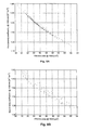
- FIG. 8A is a graph of computer simulations of non-linearity coefficient vs. effective area for the first embodiment of the present invention.
- FIG. 8B is a graph of computer simulations of non-linearity coefficient vs. effective area for conventional dual-shape dispersion-shifted optical fibers
- FIG. 9 is a graph of the refractive index profile of the cross-section of the fiber in FIG. 1 consistent with a second embodiment of the present invention.
- FIG. 10 is a graph of the refractive index profile of the cross-section of the fiber in FIG. 1 consistent with a third embodiment of the present invention
- FIG. 11 is a refractive index profile of the optical fiber in FIG. 1 consistent with a fourth embodiment of the present invention.
- FIG. 12 is a graph of total dispersion vs. wavelength for a fiber according to the fourth embodiment of the present invention.
- FIG. 13 is a refractive index profile of the fiber in FIG. 1 consistent with a fifth embodiment of the present invention.
- Optical fibers consistent with the present invention have a refractive index profile that includes two areas of peak refractive index difference in a radial dimension of the fiber, where the greater of the two peaks is positioned radially outward from the first peak.
- optical fibers having refractive index profiles of this nature can produce optical characteristics in a wavelength operating range of 1520 to 1620 nm that includes a relatively low non-linearity coefficient ⁇ and a relatively high effective area. Due to their characteristics, the invention fibers can be advantageously used, in particular, in long length (e.g., greater than 50 km) optical transmission lines and/or with high power signals (e.g., in optical transmission lines with optical amplifiers).
- optical fibers including this refractive index profile can effectively operate as nonzero dispersion fibers to minimize the non-linear effect of four-wave mixing in WDM systems, both for nonzero positive dispersion and nonzero negative dispersion. Furthermore, Applicants have determined that optical fibers including this refractive index profile can effectively operate as dispersion shifted fibers to minimize the non-linear effects in optical transmission systems.
- the optical transmission fiber with a low non-linearity coefficient ⁇ comprises a plurality of light conducting layers of glass with varying indices of refraction.
- the axial center of the fiber is an inner core 12 that has a first maximum refractive index difference ⁇ n 1 and a radius r 1 .
- refractive index difference refers to the difference in refractive index between a given layer of glass and the cladding glass. That is, the refractive index difference ⁇ n 1 of inner core 12 , having a refractive index n 1 , equals n 1 —cladding.
- Glass core 12 preferably is made of SiO 2 doped with a substance that increases the refractive index of pure SiO 2 , such as GeO 2 .
- Other dopants increasing the refractive index are for example Al 2 O 3 , P 2 O 5 , TiO 2 , ZrO 2 and Nb 2 O 3 .
- a first glass layer 14 surrounds the inner core 12 and is characterized by an index of refraction across its width that is less than the indices of refraction along the radius r 1 of inner core 12 .
- first layer 14 is made of pure SiO 2 that has a refractive index difference ⁇ n 2 substantially equal to 0.
- a second glass layer 16 surrounds the first glass layer 14 along the length of the fiber 10 .
- Second glass layer 16 has a maximum index of refraction ⁇ n 3 within its width that exceeds the maximum index of refraction of the glass ⁇ n 1 within inner core 12 .
- a low loss cladding 18 surrounds the second glass layer 16 in a conventional manner to help guide light propagating along the axis of fiber 10 .
- Cladding 18 may comprise pure SiO 2 glass with a refractive index difference substantially equal to 0. If cladding 18 includes some refractive-index-modifying dopant, the cladding should have an index of refraction across its width that is less than the maximum indices of refraction within both inner core 12 and second layer 16 .
- FIG. 2 illustrates a refractive index profile across the radius of fiber 10 for a first embodiment of the present invention.
- fiber 10 has two refractive index peaks 20 and 22 positioned respectively within inner core 12 and second layer 16 .
- First layer 14 which is disposed radially between inner core 12 and second layer 16 , provides a refractive index dip relative to its two adjacent layers 12 and 16 . Consequently, the combination of inner core 12 , first layer 14 , and second layer 16 generally provides an optical fiber profile having a segmented core with an outer layer having the highest index of refraction within the cross-section of the fiber.
- inner core 12 has a radius r 1 that is about 3.6 ⁇ m to 4.2 ⁇ m, but preferably is about 3.9 ⁇ m. Between the center of the fiber and the radial position at 3.9 m, inner core 12 includes a refractive-index-increasing dopant such as GeO 2 or the like that produces a peak index of refraction at or near the axial center of fiber 10 and a minimum for the inner core at its outer radius. At the peak, the refractive index difference for inner core 12 is about 0.0082 to 0.0095, but preferably is about 0.0085.
- a refractive-index-increasing dopant such as GeO 2 or the like that produces a peak index of refraction at or near the axial center of fiber 10 and a minimum for the inner core at its outer radius. At the peak, the refractive index difference for inner core 12 is about 0.0082 to 0.0095, but preferably is about 0.0085.
- the concentration of the refractive-index-increasing dopant decreases from the center of inner core 12 to the outer radius at about 3.9 ⁇ m in a manner to produce a profile having a curved slope that resembles a substantially parabolic shape.
- the preferred substantially parabolic shape corresponds to a profile ⁇ of between about 1.7 and 2.0, but preferably of about 1.9.
- the refractive index profile becomes more nearly a step index profile.
- a true step index is described by an ⁇ of infinity, but an ⁇ of about 4 to 6 is a step index profile for practical purposes.
- the profile ⁇ may have an index depression, in the shape of an inverted cone, along its centerline, for example if the fiber is produced by the OVD or MCVD methods.
- First glass layer 14 has a refractive index difference ⁇ n 2 , referenced as 24 , that is less than ⁇ n 1 .
- the preferred refractive index difference ⁇ n 2 for first glass layer 14 has a constant value of about 0, which corresponds to a layer of pure SiO 2 glass.
- the refractive index difference ⁇ n 2 of first glass layer may differ from zero, due to the presence of refractive index modifying dopants, provided that the dopant content of first glass layer 14 is low. It is envisaged that the refractive index difference varies across first glass layer. In any case, refractive-index-modifying dopants from inner core 12 or from second glass layer 16 may diffuse into first glass layer 14 during fiber fabrication.
- a low-dopant content in first glass layer 14 corresponds to a dopant content such as to cause a refractive index difference ⁇ n 2 for first glass layer 14 (in absolute value) of about, or preferably lower than, 15% of the fiber peak refractive index difference, i.e. of the refractive index difference ⁇ n 3 of second glass layer 16 .
- the skilled in the art can adapt this value so that the resulting optical fiber has non-linear and/or loss characteristics matching the characteristics of an optical system that he/she intends to make, such as length of the optical transmission line, amplifier number and spacing and/or power, number and wavelength spacing of the transmission signals.
- improved fiber characteristics can be achieved by a dopant concentration in first glass layer 14 such as to cause a refractive index difference ⁇ n 2 that is lower in absolute value than 10% of refractive index difference ⁇ n 3 of second glass layer 16 .
- This low dopant content in first glass layer in combination with a relatively high field intensity in that region, gives a very limited contribution to the fiber non-linearity coefficient and loss.
- Still more preferred fiber characteristics can be achieved by a refractive index difference ⁇ n 2 lower, in absolute value, than 5% of refractive index difference ⁇ n 3 of second glass layer 16 .
- First glass layer 14 has an outer radius r 2 which, as shown in FIG. 2, is between about 9.0 ⁇ m and 12.0 ⁇ m, but preferably is 9.2 ⁇ m. As a correspondingt, first glass layer 14 has a width extending from about 4.8 ⁇ m to about 8.4 ⁇ m for a first embodiment of the present invention.
- Second glass layer 16 like inner core 12 , has its refractive index difference increased by doping the width of the glass layer with GeO 2 and/or other well-known dopants. Second glass layer 16 has a substantially parabolic profile across its radius that culminates in a maximum refractive index difference ⁇ n 3 , depicted as 22 in FIG. 2, that exceeds the maximum refractive index difference ⁇ n 1 of glass core 12 and refractive index difference ⁇ n 2 of first layer 14 . Index profiles other than parabolic, e.g., rounded or step like, are also envisaged for second glass layer 16 .
- the index of refraction ⁇ n 3 of second glass layer 16 at its peak exceeds the peak index of refraction ⁇ n 1 for inner core 12 by more than 5%.
- the index of refraction ⁇ n 3 of second glass layer 16 at its peak is about 0.009 to 0.012, but preferably is about 0.0115.
- Second glass layer 16 has a width w that equals about 0.6 ⁇ m to 1.0 ⁇ m, but preferably is about 0.9 ⁇ m.
- Cladding 18 of optical fiber 10 has a refractive index profile 26 that has a refractive index difference substantially equal to 0.
- cladding 26 preferably is pure SiO 2 glass but may include dopants that do not raise its index of refraction above that of the maximum indices of refraction 20 and 22 of inner core 12 and second layer 16 .
- optical transmission fiber 10 with the refractive index profile of FIG. 2 has several desirable optical characteristics for use in WDM transmission.
- optical transmission fiber 10 is used in a transmission system that operates over a wavelength range of 1530 nm to 1565 nm where the fiber provides a total dispersion of 5 to 10 ps/nm/km across that operating wavelength range. More particularly, fiber 10 exhibits in the above wavelength range the following optical characteristics, with the characteristics of the most preferred embodiment in parentheses:
- the non-linearity coefficient ⁇ provides an indication of the susceptibility of a fiber to non-linear effects.
- fiber 10 With ⁇ of less than 2 W ⁇ 1 km ⁇ 1 , fiber 10 exhibits favorable response in high power optical transmission systems that may otherwise initiate severe problems from self-phase modulation, cross-phase modulation, and the like.
- fiber 10 includes a nonzero dispersion value across the operating range of 1530 nm to 1565 nm, which helps to deter detrimental four-wave mixing.
- the relatively small slope of total dispersion across the operating wavelength range enables fiber 10 to provide relatively small differences of dispersion between carrier wavelengths in a WDM system.
- FIGS. 3-6 more fully illustrate the relationships between the physical and optical characteristics of fiber 10 .
- These figures present results from computer simulationrs for fiber 10 for various physical and optical relationships when considering six parameters: radius r 1 of inner core 12 , maximum index of refraction ⁇ n 1 of inner core 12 , profile shape ⁇ for inner core 12 , outer radius r 2 of first layer 14 , width w of second layer 16 , and maximum index of refraction ⁇ n 3 of second layer 16 .
- these six parameters were varied essentially at random substantially across the ranges for the six parameters outlined above, i.e.
- Each dot represents a different set of the six parameters.
- the simulation considered only parameter sets having ⁇ n 1 ⁇ n 3 . Accordingly, all dots correspond to fibers having an outer refractive index peak higher than the inner peak.
- the area of the refractive index profile for inner core 12 should be lowered.
- An outer ring of increased refractive index, specifically second glass layer 16 is added to help obtain a high effective area and a low non-linearity coefficient for fiber 10 .
- the addition of the second glass layer of increased index of refraction heightens the electrical field distribution in the cross-section of the fiber in regions with low dopant content, lowering it at the center of the fiber, so that the non-linearity coefficient ⁇ remains low.
- FIG. 3 illustrates the relationship between the radius r 1 and the dispersion for fiber 10 .
- the value of r 1 is preferably less than 3 ⁇ , to achieve a monomodal behavior at a given wavelength ⁇ .
- a proper range of radial dimension r 1 for the refractive index profile may be determined.
- the effective area of fiber 10 should be kept relatively high, preferably in excess of 45 ⁇ m 2 . It is possible to lower the noninearity coefficient in two ways: either reducing the area of the refractive index profile for the inner core (i.e., the area of the region between peak 20 and the co-ordinate axes in FIG. 2) (FIGS. 4 - 5 ), or increasing the refractive index of the second outer peak (FIG. 6 ).
- FIGS. 4 and 5 show the former effect for a series of computer simulations. For the sake of clarity, the radial dimension r 1 in the simulations was kept constant, and so dispersion is essentially determined, in these figures.
- the decrease in area also provides a lower non-linearity coefficient ⁇ , as shown in FIG. 5 .
- the fiber 10 with a lower non-linearity coefficient ⁇ can handle increased power and/or have decreased non-linear effects.
- Applicants have recognized that the addition of a lateral area of higher index of refraction positioned radially outward from the inner core will help to obtain a relatively large effective area and therefore low non-linearity coefficient ⁇ .
- the addition of this lateral peak refractive index zone helps to make the electrical field distribution larger but does not substantially affect dispersion.
- FIG. 6 shows results of a computer simulation comparing effective area and the peak index of refraction difference for second layer 16 , where other fiber parameters are kept constant for the sake of clarity.
- an increasing index of refraction difference for the outer ring 16 generates an increasing effective area for fiber 10 .
- FIG. 7 illustrates the spread of electric field within the cross-section of fiber 10 due to the addition of outer ring 16 .
- references 20 and 22 denote an inner core and an outer ring, respectively, while reference 23 denotes the electrical field distribution across the fiber radius. The presence of the outer peak enlarges the electric field distribution in the fiber.
- FIG. 8A illustrates the simulated relationship between ⁇ and effective area for fibers 10 according to the first embodiment.
- FIG. 8B illustrates the simulated relationship between ⁇ and effective area for conventional dual-shape dispersion-shifted optical fibers, which exhibit a less desirable (i.e., a higher) A eff ⁇ product.
- fiber 10 provides an optical waveguide with a unique refractive index profile for transmitting optical WDM signal with nonzero dispersion and a relatively low non linearity coefficient. These features enable fiber 10 to minimize signal degradation due to four-wave mixing and/or to permit the use of higher power.
- FIG. 9 illustrates a second embodiment of the present invention for optical fiber 10 of FIG. 1 .
- inner core 12 has a radius r 1 that is about 2.3 ⁇ m to 3.6 ⁇ m, but preferably is about 2.77 ⁇ m.
- inner core 12 includes one or more refractive-index-increasing dopants, such as GeO 2 or the like, that produce a peak index of refraction at or near the axial center of fiber 10 and a minimum for the inner core at its outer radius.
- the index of refraction ⁇ n 1 for inner core 12 in the second embodiment is about 0.010 to about 0.012, and preferably is about 0.0113.
- the concentration of the refractive-index-modifying dopant in the core 12 decreases from the center to the outer radius at about 2.77 ⁇ m in a manner to produce a profile having a profile a of about 1.4 to about 3.0, but preferably of about 2.42.
- First glass layer 14 in the second embodiment has a substantially constant refractive index difference ⁇ n 2 , referenced as 24 , that is about 0, due to undoped silica glass.
- low dopant concentrations can be present in first glass layer 14 .
- the first layer 14 extends to an outer radius r 2 equal to between about 4.4 ⁇ m and 6.1 ⁇ m, but preferably equal to 5.26 ⁇ m.
- first glass layer 14 has a width extending from about 0.8 ⁇ m to about 3.8 ⁇ m, but preferably of about 2.49 ⁇ m, for a second embodiment of the present invention.
- the second embodiment includes a second glass layer 16 , like inner core 12 , with its refractive index difference increased by doping the width of the glass layer with GeO 2 and/or other well-known refractive-index-increasing dopants.
- Second glass layer 16 has a substantially parabolic profile across its radius that culminates in a maximum refractive index difference ⁇ n 3 , depicted as 22 in FIG. 9 .
- Index profiles other than parabolic, e.g., rounded or step like, are also envisaged for second glass layer 16 .
- the index of refraction ⁇ n 3 of second glass layer 16 at its peak exceeds the peak index of refraction ⁇ n 1 for inner core 12 by more than 5%.
- the index of refraction ⁇ n 3 of second glass layer 16 at its peak is about 0.012 to 0.014, but preferably is about 0.0122.
- Second glass layer 16 has a width w that equals about 1.00 ⁇ m to about 1.26 ⁇ m, but preferably is about 1.24 ⁇ m.
- optical transmission fiber 10 is used in a transmission system that operates over a wavelength range of 1530 nm to 1565 nm where the fiber provides positive nonzero dispersion characteristics.
- Nonzero dispersion fibers are described in ITU-T Recommendation G.655.
- Fiber 10 constructed according to the second embodiment of FIG. 9 exhibits the following preferred optical characteristics (the values are given for a value of 1550 nm, unless otherwise indicated):
- the second embodiment for fiber 10 having the above-listed optical characteristics provides acceptable conditions for the transmission of both solitons and non-soliton WDM systems.
- FIG. 10 depicts a refractive index profile of a third embodiment of the present invention for optical fiber 10 , whose cross-section is shown in FIG. 1 .
- the third embodiment like the first and second embodiments, includes an inner core with a heightened refractive index difference ⁇ n 1 and a profile shape ⁇ , together with a first layer of glass having a lower refractive index difference ⁇ n 2 and a second layer of glass having the maximum index of refraction difference ⁇ n 3 in the cross-section of the fiber.
- the following sets forth the preferred physical parameters for fiber 10 according to the third embodiment of the present invention as illustrated in FIG. 10 .
- Second Layer Width w 1.129 ⁇ m
- Second Layer Refractive Index Difference ⁇ n 3 0.0129.
- Fiber 10 according to the third embodiment of the present invention advantageously obtains the following optimal optical characteristics (at a wavelength of 1550 nm):
- the third embodiment for fiber 10 having the above-listed optical characteristics provides acceptable conditions for the transmission in both solitons and non-soliton WDM systems.
- FIG. 11 illustrates a fourth refractive index profile for optical fiber 10 that generates optical characteristics of nonzero positive dispersion.
- the physical characteristics of the inventive fiber of FIG. 11 include a radius r 1 for inner core 12 of about 3.2 ⁇ m, an index of refraction profile a for inner core 12 of about 2.9, a maximum refractive index difference ⁇ n 1 at reference 20 for inner core 12 of about 0.0088, an outer radius of first glass layer 14 of about 7.2 ⁇ m with an index of refraction ⁇ n 2 at reference 24 of about 0, a width of second glass layer 16 of about 0.8 ⁇ m, and a maximum index of refraction ⁇ n 3 at reference 22 of the second glass layer 16 of about 0.0119.
- the profile of FIG. 11 for the nonzero positive dispersion fiber has the characteristic multiple peaks high refractive index, where the outer peak is present in the second glass layer 16 , has a substantially parabolic shape, and at its maximum 22 exceeds the maximum index of refraction 20 within inner core 12 .
- Fiber 10 having the refractive index profile of FIG. 11 provides positive total fiber dispersion across the operating wavelength band of 1530 nm to 1565 nm. Such a performance has desirable application in optical systems that have a relatively high optical power and would otherwise generate deleterious four-wave mixing products.
- FIG. 12 depicts the simulated total dispersion vs. wavelength for optical fiber 10 having the refractive index profile of FIG. 11 . As shown in this figure, the refractive index profile of FIG. 11 produces dispersion across the wavelength band of about 1530 nm to 1565 nm that stretches between about 0.76 ps/km/nm and 3.28 ps/km/nm. Specifically, the fiber with the refractive index profile shown in FIG. 11 provides the following optical characteristics at 1550 nm:
- FIG. 13 illustrates a fifth refractive index profile for optical fiber 10 that generates optical characteristics of nonzero negative dispersion with relatively low non-linearity coefficient.
- the physical characteristics of the inventive fiber of FIG. 13 include a radius r 1 for inner core 12 of about 2.4 ⁇ m to 3.2 ⁇ m and preferably of about 2.6 ⁇ m, an index of refraction profile ⁇ for inner core 12 of about 1.8 to 3.0 and preferably of about 2.48, a maximum refractive index difference ⁇ n 1 at reference 20 for inner core 12 of about 0.0106-0.0120 and preferably of about 0.0116, an outer radius of first glass layer 14 of about 5.3 ⁇ m to 6.31 ⁇ m and preferably of about 5.9 ⁇ m with an index of refraction ⁇ n 2 at reference 24 preferably of about 0, a width of second glass layer 16 of about 1.00 ⁇ m to 1.08 ⁇ m and preferably of about 1.08 ⁇ m, and a maximum index of refraction ⁇ n 3 at reference 22 of the second glass
- the profile of FIG. 13 for the nonzero negative dispersion fiber has the characteristic multiple peaks of high refractive index, where the outer peak is present in the second glass layer 16 , has a substantially parabolic shape, and at its maximum 22 exceeds the maximum index of refraction 20 within inner core 12 .
- Index profiles other than parabolic, e.g., rounded or step like, are also envisaged for second glass layer 16 .
- the index of refraction ⁇ n 3 of second glass layer 16 at its peak exceeds the peak index of refraction ⁇ n 1 for inner core 12 by more-than 5%.
- Fiber 10 having the refractive index profile of FIG. 13 provides negative total fiber dispersion across the operating wavelength band of 1530 nm to 1565 nm. Such a performance has desirable application in optical systems used in underwater transmission systems that have a relatively high optical power and would otherwise generate deleterious four-wave mixing products.
- the fiber with the refractive index profile shown in FIG. 13 provides the following optical characteristics at 1550 nm, with the characteristics of the most preferred embodiment in parentheses:
- a sixth refractive index profile for optical fiber 10 will now be described that generates optical characteristics of shifted dispersion with relatively low non-linearity coefficient.
- Dispersion shifted fibers are described in ITU-T Recommendation G.653.
- the physical characteristics of the fiber according to the sixth embodiment include a radius r 1 for inner core 12 of about 3.2 ⁇ m, an index of refraction profile ⁇ for inner core 12 of about 2.8, a maximum refractive index difference ⁇ n 1 at reference 20 for inner core 12 of about 0.0092, an outer radius of first glass layer 14 of about 7.8 ⁇ m with an index of refraction ⁇ n 2 of about 0, a width of second glass layer 16 of about 0.8 ⁇ m, and a maximum index of refraction ⁇ n 3 of the second glass layer 16 of about 0.0118.
- the profile according to the sixth embodiment for the dispersion shifted fiber has the characteristic multiple peaks of high refractive index, where the outer peak is present in the second glass layer 16 , has a substantially parabolic shape, and at its maximum 22 exceeds the maximum index of refraction 20 within inner core 12 .
- Index profiles other than parabolic, e.g., rounded or step like, are also envisaged for second glass layer 16 .
- the index of refraction ⁇ n 3 of second glass layer 16 at its peak exceeds the peak index of refraction ⁇ n 1 for inner core 12 by more than 5%.
- Fiber 10 having the refractive index profile of FIG. 13 provides low absolute value total fiber dispersion across the operating wavelength band of 1530 nm to 1565 nm.
- the fiber provides the following optical characteristics, given at 1550 nm unless otherwise indicated:
- ⁇ cutoff 1359 nm (fiber cutoff wavelength according to ITU.T G.650)
Abstract
Description


Claims (13)
Priority Applications (2)
| Application Number | Priority Date | Filing Date | Title |
|---|---|---|---|
| US09/984,170 US6507689B2 (en) | 1998-06-19 | 2001-10-29 | Optical fiber having low non-linearity for WDM transmission |
| US10/342,882 US6922514B2 (en) | 1998-06-19 | 2003-01-14 | Optical fiber having low non-linearity for WDM transmission |
Applications Claiming Priority (6)
| Application Number | Priority Date | Filing Date | Title |
|---|---|---|---|
| EP98111292 | 1998-06-19 | ||
| EP98111292.3 | 1998-06-19 | ||
| EP98111292 | 1998-06-19 | ||
| US9079198P | 1998-06-25 | 1998-06-25 | |
| US09/335,509 US6321016B1 (en) | 1998-06-19 | 1999-06-18 | Optical fiber having low non-linearity for WDM transmission |
| US09/984,170 US6507689B2 (en) | 1998-06-19 | 2001-10-29 | Optical fiber having low non-linearity for WDM transmission |
Related Parent Applications (1)
| Application Number | Title | Priority Date | Filing Date |
|---|---|---|---|
| US09/335,509 Continuation US6321016B1 (en) | 1998-06-19 | 1999-06-18 | Optical fiber having low non-linearity for WDM transmission |
Related Child Applications (1)
| Application Number | Title | Priority Date | Filing Date |
|---|---|---|---|
| US10/342,882 Continuation US6922514B2 (en) | 1998-06-19 | 2003-01-14 | Optical fiber having low non-linearity for WDM transmission |
Publications (2)
| Publication Number | Publication Date |
|---|---|
| US20020090187A1 US20020090187A1 (en) | 2002-07-11 |
| US6507689B2 true US6507689B2 (en) | 2003-01-14 |
Family
ID=27239095
Family Applications (3)
| Application Number | Title | Priority Date | Filing Date |
|---|---|---|---|
| US09/335,509 Expired - Lifetime US6321016B1 (en) | 1998-06-19 | 1999-06-18 | Optical fiber having low non-linearity for WDM transmission |
| US09/984,170 Expired - Lifetime US6507689B2 (en) | 1998-06-19 | 2001-10-29 | Optical fiber having low non-linearity for WDM transmission |
| US10/342,882 Expired - Lifetime US6922514B2 (en) | 1998-06-19 | 2003-01-14 | Optical fiber having low non-linearity for WDM transmission |
Family Applications Before (1)
| Application Number | Title | Priority Date | Filing Date |
|---|---|---|---|
| US09/335,509 Expired - Lifetime US6321016B1 (en) | 1998-06-19 | 1999-06-18 | Optical fiber having low non-linearity for WDM transmission |
Family Applications After (1)
| Application Number | Title | Priority Date | Filing Date |
|---|---|---|---|
| US10/342,882 Expired - Lifetime US6922514B2 (en) | 1998-06-19 | 2003-01-14 | Optical fiber having low non-linearity for WDM transmission |
Country Status (1)
| Country | Link |
|---|---|
| US (3) | US6321016B1 (en) |
Cited By (15)
| Publication number | Priority date | Publication date | Assignee | Title |
|---|---|---|---|---|
| US20030128948A1 (en) * | 1998-06-19 | 2003-07-10 | Pirelli Cavi E Sistemi S.P.A. | Optical fiber having low non-linearity for WDM transmission |
| US20030210877A1 (en) * | 2000-12-12 | 2003-11-13 | Berkey George E. | Large effective area optical fiber |
| WO2004011976A1 (en) * | 2002-07-31 | 2004-02-05 | Corning Incorporated | Non-zero dispersion shifted optical fiber with depressed core having large effective area, low slope and low dispersion |
| US20040067034A1 (en) * | 2002-07-31 | 2004-04-08 | Rosenblum Steven S. | Non-zero dispersion shifted optical fiber having large effective area, low slope and low zero dispersion |
| US20040071419A1 (en) * | 2002-10-11 | 2004-04-15 | Berkey Geroge E. | Positive dispersion optical fiber |
| US20040095968A1 (en) * | 2002-11-20 | 2004-05-20 | The Boeing Company | Fiber amplifier having a non-doped inner core and at least one doped gain region |
| US20040213510A1 (en) * | 1999-10-22 | 2004-10-28 | Corvis Corporation | Optical fiber transmission system using RZ pulses |
| US20050094955A1 (en) * | 2003-10-30 | 2005-05-05 | Bickham Scott R. | Dispersion compensating fiber for moderate dispersion NZDSF and transmission system utilizing same |
| US20050135735A1 (en) * | 2003-12-19 | 2005-06-23 | Bernhard Deutsch | Architectures for optical networks |
| US7050687B2 (en) | 2002-02-15 | 2006-05-23 | Corning Incorporated | Low slope dispersion shifted optical fiber |
| WO2009152375A1 (en) * | 2008-06-11 | 2009-12-17 | Solar Implant Technologies Inc. | Solar cell fabrication using implantation |
| US20100323508A1 (en) * | 2009-06-23 | 2010-12-23 | Solar Implant Technologies Inc. | Plasma grid implant system for use in solar cell fabrications |
| US20110162703A1 (en) * | 2009-03-20 | 2011-07-07 | Solar Implant Technologies, Inc. | Advanced high efficientcy crystalline solar cell fabrication method |
| US9318332B2 (en) | 2012-12-19 | 2016-04-19 | Intevac, Inc. | Grid for plasma ion implant |
| US9324598B2 (en) | 2011-11-08 | 2016-04-26 | Intevac, Inc. | Substrate processing system and method |
Families Citing this family (27)
| Publication number | Priority date | Publication date | Assignee | Title |
|---|---|---|---|---|
| GB9814526D0 (en) * | 1998-07-03 | 1998-09-02 | Univ Southampton | Optical fibre and optical fibre device |
| DE19839870A1 (en) * | 1998-09-02 | 2000-03-09 | Deutsche Telekom Ag | Single-mode optical fiber |
| US6556756B2 (en) * | 1999-03-17 | 2003-04-29 | Corning Incorporated | Dispersion shifted optical waveguide fiber |
| US7155095B2 (en) * | 1999-03-29 | 2006-12-26 | Furukawa Electric Co., Ltd. | Method for efficient four-wave mixing generation and short pulse generation equipment using the method |
| WO2001031372A1 (en) * | 1999-10-22 | 2001-05-03 | Showa Electric Wire & Cable Co., Ltd. | Optical attenuator |
| JP4487420B2 (en) * | 2000-12-22 | 2010-06-23 | 富士通株式会社 | Optical amplification transmission system |
| US6490398B2 (en) * | 2001-02-21 | 2002-12-03 | Fitel Usa Corp. | Dispersion-compensating fiber having a high figure of merit |
| US6542678B2 (en) * | 2001-03-19 | 2003-04-01 | Lucent Technologies, Inc. | High-dispersion fibers for high-speed transmission |
| US7043125B2 (en) * | 2001-07-30 | 2006-05-09 | Corning Incorporated | Optical waveguide fiber for local access |
| FR2828742B1 (en) * | 2001-08-16 | 2004-01-16 | Cit Alcatel | CONTINUOUSLY CHANGING FIBER OF CHROMATIC DISPERSION |
| US20040081414A1 (en) * | 2002-10-28 | 2004-04-29 | Barker Delmar L. | Type of optical/RF transmission fiber constructed from left handed materials (LHM) with air core capable of high power transmission |
| US6904217B2 (en) * | 2003-01-29 | 2005-06-07 | Furukawa Electric North America | Method for the manufacture of optical fibers, improved optical fibers, and improved Raman fiber amplifier communication systems |
| US7170214B2 (en) * | 2003-09-08 | 2007-01-30 | New Scale Technologies, Inc. | Mechanism comprised of ultrasonic lead screw motor |
| US6940209B2 (en) * | 2003-09-08 | 2005-09-06 | New Scale Technologies | Ultrasonic lead screw motor |
| US7309943B2 (en) * | 2003-09-08 | 2007-12-18 | New Scale Technologies, Inc. | Mechanism comprised of ultrasonic lead screw motor |
| US7024083B2 (en) * | 2004-02-20 | 2006-04-04 | Corning Incorporated | Non-zero dispersion shifted optical fiber |
| US7106934B1 (en) * | 2005-06-30 | 2006-09-12 | Corning Incorporated | Non-zero dispersion shifted optical fiber |
| JP2009517702A (en) * | 2005-11-23 | 2009-04-30 | コーニング インコーポレイテッド | Low attenuation / non-zero dispersion shifted optical fiber |
| US7764854B2 (en) * | 2005-12-27 | 2010-07-27 | Ofs Fitel Llc | Optical fiber with specialized index profile to compensate for bend-induced distortions |
| US7783149B2 (en) * | 2005-12-27 | 2010-08-24 | Furukawa Electric North America, Inc. | Large-mode-area optical fibers with reduced bend distortion |
| CN100424529C (en) * | 2006-06-13 | 2008-10-08 | 富通集团有限公司 | A low bending loss superfine low water peak fiber |
| EP2179480B1 (en) * | 2007-07-16 | 2015-01-21 | Coractive High-Tech Inc. | Light emitting devices with phosphosilicate glass |
| US7817681B2 (en) * | 2008-06-26 | 2010-10-19 | Corning Incorporated | Pulse stretching optical fiber and related systems and methods |
| JP5779606B2 (en) * | 2013-03-14 | 2015-09-16 | 株式会社フジクラ | Amplifying optical fiber and fiber laser device using the same |
| US9983376B2 (en) * | 2015-04-23 | 2018-05-29 | Corning Optical Communications LLC | High-data-rate electrical interconnect cables |
| CN110678790B (en) | 2017-06-02 | 2021-01-26 | 康普技术有限责任公司 | Concentric optical fibers for space division multiplexed optical communications and methods of use thereof |
| US20210247564A1 (en) * | 2020-02-03 | 2021-08-12 | Corning Incorporated | Low loss and low dispersion optical fiber for data center optical communication |
Citations (11)
| Publication number | Priority date | Publication date | Assignee | Title |
|---|---|---|---|---|
| US4690504A (en) * | 1984-06-04 | 1987-09-01 | Shin-Etsu Chemical Co., Ltd. | Quartz glass-made optical fibers and a method for the preparation thereof |
| US4715679A (en) * | 1981-12-07 | 1987-12-29 | Corning Glass Works | Low dispersion, low-loss single-mode optical waveguide |
| US4877304A (en) * | 1987-09-09 | 1989-10-31 | Corning Incorporated | Few-mode/single-mode fiber |
| US4889404A (en) * | 1987-09-09 | 1989-12-26 | Corning Incorporated | Asymmetrical bidirectional telecommunication system |
| US5555340A (en) * | 1994-03-23 | 1996-09-10 | Sumitomo Electric Industries, Ltd. | Optical transmission system with dispersion compensating optical fiber |
| US5579428A (en) * | 1995-06-07 | 1996-11-26 | Corning Incorporated | Solitons in dispersion flattened waveguide |
| US5684909A (en) * | 1996-02-23 | 1997-11-04 | Corning Inc | Large effective area single mode optical waveguide |
| US5963700A (en) * | 1997-02-26 | 1999-10-05 | Nippon Telegraph And Telephone Corporation | Optical fiber |
| US6025954A (en) * | 1994-07-25 | 2000-02-15 | Pirelli S.P.A. | Amplified telecommunication system for wavelength-division multiplexing transmissions, having an equalized reception power |
| US6192179B1 (en) * | 1999-01-25 | 2001-02-20 | Corning Incorporated | Distributed resonant ring fiber filter |
| US6321016B1 (en) * | 1998-06-19 | 2001-11-20 | Pirelli Cavi E Sistemi S.P.A. | Optical fiber having low non-linearity for WDM transmission |
Family Cites Families (7)
| Publication number | Priority date | Publication date | Assignee | Title |
|---|---|---|---|---|
| US5327516A (en) * | 1993-05-28 | 1994-07-05 | At&T Bell Laboratories | Optical fiber for wavelength division multiplexing |
| US5504829A (en) * | 1993-12-27 | 1996-04-02 | Corning Incorporated | Optical fiber for soliton transmission and method of making |
| US5835655A (en) | 1995-01-26 | 1998-11-10 | Corning Incorporated | Large effective area waveguide fiber |
| US6011638A (en) | 1996-02-12 | 2000-01-04 | Lucent Technologies Inc. | Dispersion tapered optical fibers for use in WDM soliton transmission systems |
| AU715435B2 (en) | 1996-02-12 | 2000-02-03 | Corning Incorporated | Single mode optical waveguide having large effective area |
| EP0798578A1 (en) | 1996-03-22 | 1997-10-01 | Corning Incorporated | Dispersion shifted optical waveguide fiber |
| US5905838A (en) * | 1998-02-18 | 1999-05-18 | Lucent Technologies Inc. | Dual window WDM optical fiber communication |
-
1999
- 1999-06-18 US US09/335,509 patent/US6321016B1/en not_active Expired - Lifetime
-
2001
- 2001-10-29 US US09/984,170 patent/US6507689B2/en not_active Expired - Lifetime
-
2003
- 2003-01-14 US US10/342,882 patent/US6922514B2/en not_active Expired - Lifetime
Patent Citations (11)
| Publication number | Priority date | Publication date | Assignee | Title |
|---|---|---|---|---|
| US4715679A (en) * | 1981-12-07 | 1987-12-29 | Corning Glass Works | Low dispersion, low-loss single-mode optical waveguide |
| US4690504A (en) * | 1984-06-04 | 1987-09-01 | Shin-Etsu Chemical Co., Ltd. | Quartz glass-made optical fibers and a method for the preparation thereof |
| US4877304A (en) * | 1987-09-09 | 1989-10-31 | Corning Incorporated | Few-mode/single-mode fiber |
| US4889404A (en) * | 1987-09-09 | 1989-12-26 | Corning Incorporated | Asymmetrical bidirectional telecommunication system |
| US5555340A (en) * | 1994-03-23 | 1996-09-10 | Sumitomo Electric Industries, Ltd. | Optical transmission system with dispersion compensating optical fiber |
| US6025954A (en) * | 1994-07-25 | 2000-02-15 | Pirelli S.P.A. | Amplified telecommunication system for wavelength-division multiplexing transmissions, having an equalized reception power |
| US5579428A (en) * | 1995-06-07 | 1996-11-26 | Corning Incorporated | Solitons in dispersion flattened waveguide |
| US5684909A (en) * | 1996-02-23 | 1997-11-04 | Corning Inc | Large effective area single mode optical waveguide |
| US5963700A (en) * | 1997-02-26 | 1999-10-05 | Nippon Telegraph And Telephone Corporation | Optical fiber |
| US6321016B1 (en) * | 1998-06-19 | 2001-11-20 | Pirelli Cavi E Sistemi S.P.A. | Optical fiber having low non-linearity for WDM transmission |
| US6192179B1 (en) * | 1999-01-25 | 2001-02-20 | Corning Incorporated | Distributed resonant ring fiber filter |
Cited By (34)
| Publication number | Priority date | Publication date | Assignee | Title |
|---|---|---|---|---|
| US6922514B2 (en) * | 1998-06-19 | 2005-07-26 | Pirelli & C. S.P.A. | Optical fiber having low non-linearity for WDM transmission |
| US20030128948A1 (en) * | 1998-06-19 | 2003-07-10 | Pirelli Cavi E Sistemi S.P.A. | Optical fiber having low non-linearity for WDM transmission |
| US20040213510A1 (en) * | 1999-10-22 | 2004-10-28 | Corvis Corporation | Optical fiber transmission system using RZ pulses |
| US6941037B2 (en) * | 1999-10-22 | 2005-09-06 | Corvis Algety Sa | Optical fiber transmission system using RZ pulses |
| US20030210877A1 (en) * | 2000-12-12 | 2003-11-13 | Berkey George E. | Large effective area optical fiber |
| US6760527B2 (en) * | 2000-12-12 | 2004-07-06 | Corning Incorporated | Large effective area optical fiber |
| US7050687B2 (en) | 2002-02-15 | 2006-05-23 | Corning Incorporated | Low slope dispersion shifted optical fiber |
| WO2004011976A1 (en) * | 2002-07-31 | 2004-02-05 | Corning Incorporated | Non-zero dispersion shifted optical fiber with depressed core having large effective area, low slope and low dispersion |
| US20040067034A1 (en) * | 2002-07-31 | 2004-04-08 | Rosenblum Steven S. | Non-zero dispersion shifted optical fiber having large effective area, low slope and low zero dispersion |
| US7181118B2 (en) | 2002-07-31 | 2007-02-20 | Corning Incorporated | Non-zero dispersion shifted optical fiber having large effective area, low slope and low zero dispersion |
| US6865328B2 (en) | 2002-10-11 | 2005-03-08 | Corning Incorporated | Positive dispersion optical fiber |
| US20040071419A1 (en) * | 2002-10-11 | 2004-04-15 | Berkey Geroge E. | Positive dispersion optical fiber |
| US6965469B2 (en) * | 2002-11-20 | 2005-11-15 | The Boeing Company | Fiber amplifier having a non-doped inner core and at least one doped gain region |
| US20040095968A1 (en) * | 2002-11-20 | 2004-05-20 | The Boeing Company | Fiber amplifier having a non-doped inner core and at least one doped gain region |
| US20050094955A1 (en) * | 2003-10-30 | 2005-05-05 | Bickham Scott R. | Dispersion compensating fiber for moderate dispersion NZDSF and transmission system utilizing same |
| US6985662B2 (en) | 2003-10-30 | 2006-01-10 | Corning Incorporated | Dispersion compensating fiber for moderate dispersion NZDSF and transmission system utilizing same |
| US20050135735A1 (en) * | 2003-12-19 | 2005-06-23 | Bernhard Deutsch | Architectures for optical networks |
| US8697553B2 (en) | 2008-06-11 | 2014-04-15 | Intevac, Inc | Solar cell fabrication with faceting and ion implantation |
| WO2009152375A1 (en) * | 2008-06-11 | 2009-12-17 | Solar Implant Technologies Inc. | Solar cell fabrication using implantation |
| US20090309039A1 (en) * | 2008-06-11 | 2009-12-17 | Solar Implant Technologies Inc. | Application specific implant system and method for use in solar cell fabrications |
| CN102099923B (en) * | 2008-06-11 | 2016-04-27 | 因特瓦克公司 | The solar cell injected is used to make |
| CN102099923A (en) * | 2008-06-11 | 2011-06-15 | 因特瓦克公司 | Solar cell fabrication using implantation |
| US8871619B2 (en) | 2008-06-11 | 2014-10-28 | Intevac, Inc. | Application specific implant system and method for use in solar cell fabrications |
| US20110162703A1 (en) * | 2009-03-20 | 2011-07-07 | Solar Implant Technologies, Inc. | Advanced high efficientcy crystalline solar cell fabrication method |
| US8749053B2 (en) | 2009-06-23 | 2014-06-10 | Intevac, Inc. | Plasma grid implant system for use in solar cell fabrications |
| US8697552B2 (en) | 2009-06-23 | 2014-04-15 | Intevac, Inc. | Method for ion implant using grid assembly |
| US8997688B2 (en) | 2009-06-23 | 2015-04-07 | Intevac, Inc. | Ion implant system having grid assembly |
| US9303314B2 (en) | 2009-06-23 | 2016-04-05 | Intevac, Inc. | Ion implant system having grid assembly |
| US20100323508A1 (en) * | 2009-06-23 | 2010-12-23 | Solar Implant Technologies Inc. | Plasma grid implant system for use in solar cell fabrications |
| US9741894B2 (en) | 2009-06-23 | 2017-08-22 | Intevac, Inc. | Ion implant system having grid assembly |
| US9324598B2 (en) | 2011-11-08 | 2016-04-26 | Intevac, Inc. | Substrate processing system and method |
| US9875922B2 (en) | 2011-11-08 | 2018-01-23 | Intevac, Inc. | Substrate processing system and method |
| US9318332B2 (en) | 2012-12-19 | 2016-04-19 | Intevac, Inc. | Grid for plasma ion implant |
| US9583661B2 (en) | 2012-12-19 | 2017-02-28 | Intevac, Inc. | Grid for plasma ion implant |
Also Published As
| Publication number | Publication date |
|---|---|
| US6922514B2 (en) | 2005-07-26 |
| US20030128948A1 (en) | 2003-07-10 |
| US20020090187A1 (en) | 2002-07-11 |
| US6321016B1 (en) | 2001-11-20 |
Similar Documents
| Publication | Publication Date | Title |
|---|---|---|
| US6507689B2 (en) | Optical fiber having low non-linearity for WDM transmission | |
| EP1141754B1 (en) | Optical fiber for metropolitan and access network systems | |
| US6169837B1 (en) | Dispersion-flattened optical fiber | |
| US6751389B2 (en) | Optical fiber for extended wavelength band | |
| US6633713B2 (en) | Optical system and method having low loss and non-linear effects | |
| KR19980071289A (en) | Distributed Transition Fiber | |
| US6941054B2 (en) | Optical transmission link with low slope, raman amplified fiber | |
| CA2267252A1 (en) | Dispersion-shift fiber | |
| JP2003508801A (en) | Optical fiber for compensating chromatic dispersion of optical fiber having positive chromatic dispersion | |
| US7099543B2 (en) | High SBS threshold NZDS optical fiber | |
| JP2976959B2 (en) | Dispersion shift fiber | |
| EP0965866B1 (en) | Optical fiber having low non-linearity for WDM transmission | |
| US7027698B2 (en) | Optical fiber for WDM transmission | |
| US7099544B2 (en) | High SBS threshold NZDS optical fiber | |
| EP1127284B1 (en) | Optical fiber for extended wavelength band | |
| US6229946B1 (en) | Dispersion-shifted optical fiber | |
| CA2274361C (en) | Optical fiber having low non-linearity for wdm transmission | |
| AU2003259574B2 (en) | Optical transmission system and method having low non-linearity for WDM transmission | |
| EP1653262A2 (en) | Optical system and method having low loss and non-linear effects |
Legal Events
| Date | Code | Title | Description |
|---|---|---|---|
| STCF | Information on status: patent grant |
Free format text: PATENTED CASE |
|
| FPAY | Fee payment |
Year of fee payment: 4 |
|
| AS | Assignment |
Owner name: GSCP ATHENA (LUX) II S.A.R.L.,LUXEMBOURG Free format text: ASSIGNMENT OF ASSIGNORS INTEREST;ASSIGNOR:PIRELLI & C. S.P.A.;REEL/FRAME:018148/0523 Effective date: 20050728 Owner name: GSCP ATHENA (LUX) II S.A.R.L., LUXEMBOURG Free format text: ASSIGNMENT OF ASSIGNORS INTEREST;ASSIGNOR:PIRELLI & C. S.P.A.;REEL/FRAME:018148/0523 Effective date: 20050728 |
|
| AS | Assignment |
Owner name: PRYSMIAN (LUX) II S.A.R.L.,LUXEMBOURG Free format text: CHANGE OF NAME;ASSIGNOR:GSCP ATHENA (LUX) II S.A.R.L.;REEL/FRAME:018160/0418 Effective date: 20050921 Owner name: PRYSMIAN (LUX) II S.A.R.L., LUXEMBOURG Free format text: CHANGE OF NAME;ASSIGNOR:GSCP ATHENA (LUX) II S.A.R.L.;REEL/FRAME:018160/0418 Effective date: 20050921 |
|
| AS | Assignment |
Owner name: PRYSMIAN CAVI E SISTEMI ENERGIA S.R.L.,ITALY Free format text: ASSIGNMENT OF ASSIGNORS INTEREST;ASSIGNOR:PRYSMIAN (LUX) II S.A.R.L.;REEL/FRAME:018171/0452 Effective date: 20051019 Owner name: PRYSMIAN CAVI E SISTEMI ENERGIA S.R.L., ITALY Free format text: ASSIGNMENT OF ASSIGNORS INTEREST;ASSIGNOR:PRYSMIAN (LUX) II S.A.R.L.;REEL/FRAME:018171/0452 Effective date: 20051019 |
|
| FPAY | Fee payment |
Year of fee payment: 8 |
|
| SULP | Surcharge for late payment |
Year of fee payment: 7 |
|
| FPAY | Fee payment |
Year of fee payment: 12 |