US6510303B2 - Extended-life toner cartridge for a laser printer - Google Patents
Extended-life toner cartridge for a laser printer Download PDFInfo
- Publication number
- US6510303B2 US6510303B2 US09/809,579 US80957901A US6510303B2 US 6510303 B2 US6510303 B2 US 6510303B2 US 80957901 A US80957901 A US 80957901A US 6510303 B2 US6510303 B2 US 6510303B2
- Authority
- US
- United States
- Prior art keywords
- toner
- maximum level
- cartridge
- paddle
- tank
- Prior art date
- Legal status (The legal status is an assumption and is not a legal conclusion. Google has not performed a legal analysis and makes no representation as to the accuracy of the status listed.)
- Expired - Fee Related
Links
- 230000033001 locomotion Effects 0.000 claims abstract description 36
- 230000007246 mechanism Effects 0.000 abstract description 6
- 238000010586 diagram Methods 0.000 description 5
- 239000004033 plastic Substances 0.000 description 4
- 238000004804 winding Methods 0.000 description 3
- 239000006229 carbon black Substances 0.000 description 2
- 238000004519 manufacturing process Methods 0.000 description 2
- 230000003287 optical effect Effects 0.000 description 2
- 125000006850 spacer group Chemical group 0.000 description 2
- 239000004793 Polystyrene Substances 0.000 description 1
- 230000009471 action Effects 0.000 description 1
- 238000007792 addition Methods 0.000 description 1
- 238000013019 agitation Methods 0.000 description 1
- 230000005540 biological transmission Effects 0.000 description 1
- 230000008859 change Effects 0.000 description 1
- 230000001427 coherent effect Effects 0.000 description 1
- 150000001875 compounds Chemical class 0.000 description 1
- 230000003111 delayed effect Effects 0.000 description 1
- 230000005484 gravity Effects 0.000 description 1
- 230000008018 melting Effects 0.000 description 1
- 238000002844 melting Methods 0.000 description 1
- 239000000203 mixture Substances 0.000 description 1
- 230000004048 modification Effects 0.000 description 1
- 238000012986 modification Methods 0.000 description 1
- 239000000049 pigment Substances 0.000 description 1
- 229920002223 polystyrene Polymers 0.000 description 1
- 230000009467 reduction Effects 0.000 description 1
- 239000007787 solid Substances 0.000 description 1
- 239000000126 substance Substances 0.000 description 1
Images


Classifications
-
- G—PHYSICS
- G03—PHOTOGRAPHY; CINEMATOGRAPHY; ANALOGOUS TECHNIQUES USING WAVES OTHER THAN OPTICAL WAVES; ELECTROGRAPHY; HOLOGRAPHY
- G03G—ELECTROGRAPHY; ELECTROPHOTOGRAPHY; MAGNETOGRAPHY
- G03G21/00—Arrangements not provided for by groups G03G13/00 - G03G19/00, e.g. cleaning, elimination of residual charge
- G03G21/16—Mechanical means for facilitating the maintenance of the apparatus, e.g. modular arrangements
- G03G21/18—Mechanical means for facilitating the maintenance of the apparatus, e.g. modular arrangements using a processing cartridge, whereby the process cartridge comprises at least two image processing means in a single unit
- G03G21/1875—Mechanical means for facilitating the maintenance of the apparatus, e.g. modular arrangements using a processing cartridge, whereby the process cartridge comprises at least two image processing means in a single unit provided with identifying means or means for storing process- or use parameters, e.g. lifetime of the cartridge
- G03G21/1896—Mechanical means for facilitating the maintenance of the apparatus, e.g. modular arrangements using a processing cartridge, whereby the process cartridge comprises at least two image processing means in a single unit provided with identifying means or means for storing process- or use parameters, e.g. lifetime of the cartridge mechanical or optical identification means, e.g. protrusions, bar codes
-
- G—PHYSICS
- G03—PHOTOGRAPHY; CINEMATOGRAPHY; ANALOGOUS TECHNIQUES USING WAVES OTHER THAN OPTICAL WAVES; ELECTROGRAPHY; HOLOGRAPHY
- G03G—ELECTROGRAPHY; ELECTROPHOTOGRAPHY; MAGNETOGRAPHY
- G03G15/00—Apparatus for electrographic processes using a charge pattern
- G03G15/06—Apparatus for electrographic processes using a charge pattern for developing
- G03G15/08—Apparatus for electrographic processes using a charge pattern for developing using a solid developer, e.g. powder developer
- G03G15/0822—Arrangements for preparing, mixing, supplying or dispensing developer
-
- G—PHYSICS
- G03—PHOTOGRAPHY; CINEMATOGRAPHY; ANALOGOUS TECHNIQUES USING WAVES OTHER THAN OPTICAL WAVES; ELECTROGRAPHY; HOLOGRAPHY
- G03G—ELECTROGRAPHY; ELECTROPHOTOGRAPHY; MAGNETOGRAPHY
- G03G2215/00—Apparatus for electrophotographic processes
- G03G2215/08—Details of powder developing device not concerning the development directly
- G03G2215/0888—Arrangements for detecting toner level or concentration in the developing device
- G03G2215/0891—Optical detection
- G03G2215/0894—Optical detection through a light transmissive window in the developer container wall
Definitions
- This invention relates to desktop electronic laser printers and more particularly to removable/replaceable toner cartridges for use with such laser printers.
- Laser printers use a focused light beam to expose discrete portions of an image transfer drum so that these portions attract printing toner.
- Toner is a mixture of pigment (typically carbon black) and plastic.
- the toner becomes electric statically attracted to exposed portions of the image transferred drum.
- a transfer medium such as paper is passed over the rotating image transferred drum, some of the toner is laid onto the medium. Subsequently, the medium passes through a heated fuser so that the plastic is melted into permanent contact with the underlying medium.
- toner cartridges that incorporate an image transfer drum, a toner tank and a metering system and a drive mechanism for the drum and metering system.
- Modern toner cartridges often include a variety of sensors that interact with the laser printer in order to indicate the status of the cartridge. Indications relating to toner level, print quality and general cartridge function are often included.
- a large number of types and sizes of toner cartridges are currently available. Each cartridge is provided with its own set of operating perimeters and toner fill limitations. Certain cartridges, such as the Optra® S 4019/4039/4049 cartridge, available from Lexmark® utilize a complex sensing system for cartridge performance.
- the encoder wheel includes a series of slots that pass through an optical sensor so as to generate time-variable pulses as the agitator paddle is rotated around the toner tank.
- the slots include multiple set of closely spaced slots, preceded by an elongated slot that are encountered as the paddle prepares to engage the toner supply. Also provided is a dwell area that is free of slots following the multiple slots. This area is encountered as the timing gear causes the paddle spring to wind until the stop drives the paddle into the toner supply. An additional set of slots then reports movement through the toner supply. The spring causes a snap-back motion of the paddle into the free space as it reaches the top of the toner supply near the cartridge developer section.
- the slots are offset and lengthened as appropriate to provide the desired expected timing sequence to the controller in the presence of a higher toner level that causes the paddle to engage the toner, and wind the spring earlier in the rotation cycle.
- FIG. 1 is an exposed perspective view of a toner cartridge toner tank assembly according to the prior art showing the encoder wheel side thereof;
- FIG. 4 is a side cross section of the toner tank assembly of FIG. 3 in which the agitator paddle is in a position of initial contact with the toner supply;
- FIG. 5 is a side cross section of the toner tank assembly of FIG. 3 in which the agitator paddle is passing through the toner supply;
- FIG. 6 is a side cross section of the toner tank assembly of FIG. 3 in which the paddle is in a position exiting the toner supply;
- the toner is continuously agitated and urged from the “sump” of the tank bottom to the developer section 106 by rotation (curved arrow 118 ) of an agitator paddle 120 .
- the paddle is formed as a framework with a leading edge supported on a series of ribs 123 that are, in turn, connected to a central axle 124 .
- the central axle is rotationally supported at the center of the tank cylinder.
- the leading edge 122 sweeps through an arc that passes just above the inner surface of the tank, while the ribs cut through the toner, enabling the toner to pass through interstices 126 defined therebetween. In this manner, the leading edge serves to break up and drive the toner upwardly into the developer section 106 .
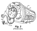
- the developer section rollers and agitator paddle are driven by a printer engine drive motor (not shown) that engages a gear train 130 (FIG. 2 ).
- the agitator paddle 120 is particular drive by a timing gear assembly 140 having an outer driven gear 142 , operatively interconnected with the print engine drive.
- the outer driven gear 142 is coaxial with an inner drive member 144 .
- the inner drive member 144 is directly and fixedly (e.g. rotationally fixed) mounted to the end 148 of the agitator axle 124 .
- the outer driven gear 142 is rotationally freewheeling with respect to the axle 124 .
- a wound coil spring 150 provides a torque between the outer driven gear 142 and the inner drive member 144 .
- a wedge-shaped cutout 154 in the outer drive member 144 enables a stop 155 on the outer driven gear 142 to rotate within a predetermined range before engaging either of the cutout end walls 156 , 158 .
- the spring 150 normally biases the stop toward the end wall 156 . As illustrated in FIG. 2, contact of the agitator paddle with the toner generates frictional resistance that tends to over-come the spring force, and causes the paddle to remain stationary while the spring 150 winds, eventually causing the stop 155 to engage the opposing cutout end wall 158 (as shown). At this point, the paddle is forced through the toner supply.
- the spring provides approximately 2-3 ounces of resistance to the paddle.
- the winding spring function is part of a sensor scheme in the prior art commercially available toner cartridge.
- the opposing end 160 of the paddle axle 124 includes a rotationally fixedly attached encoder wheel 162 .
- the encoder wheel is a thin opaque (black plastic, for example) disk having a series of through-cut holes 164 defined about its perimeter.
- the holes 164 have varying arc lengths along the circumference of the disk and varying circumferential placement with respect to each other.
- the holes 164 are adapted to pass through an optical sensor 166 (shown in phantom).
- the sensor is typically mounted on the print engine, and surrounds the perimeter area of the encoder wheel 162 when the cartridge is seated into the print engine.
- the sensor can be includes in the cartridge outer housing (not shown) and include contacts that communicate with the print engine.
- the sensor 166 consists of a light emitter 168 and a light receiver 170 each positioned on opposite sides of the wheel.
- the solid portions of the encoder wheel normally block transmission of light from the emitter to the sensor—but as holes 164 rotationally pass between the emitter and receiver, the sensor generates a time-variable pulse signal that is communicated to the print engine controller 180 .
- the encoder wheel is fixedly mounted to the agitator paddle axle 124 , the signals generated by encoder wheel movement provide a direct indication of the relative rotational position and movement speed of the paddle at various significant times within a print cycle.
- the encoder wheel and sensor shall be collectively termed as the paddle movement reporting mechanism, as they provide the controller with information regarding the state of the paddle as it moves through the tank.
- the controller 180 can comprise any commercially available microcontroller, microprocessor or other control/logic unit, and is generally part of the overall print engine electronics package.
- the controller 180 includes a timing recognition functional block 182 that interprets the pulse signals generated by the sensor in terms of time duration, spacing between pulses and overall placement versus the print cycle.
- the controller can monitor and control the print engine motor 184 shown schematically and can generate a variety of alarm and motor/print stop signals 188 (and associated computer print status codes) if the timing is outside the controller's accepted predetermined parameters.
- the cartridge 200 includes a toner tank assembly 202 having a modified cylindrical toner tank housing 204 .
- Components of the toner tank assembly 202 that are similar to those described above (FIGS. 1 and 2) have like reference numbers.
- the toner supply 208 of an original equipment manufacturer toner cartridge (prior art) is normally limited to a maximum level indicated by the dashed line 210 .
- the manner in which toner supply is limited is related directly to the expected output of time-variable pulse signals, which is in turn based upon rotation of the encoder wheel.
- the overall movement pattern of the agitator paddle (passing into, through and out of the toner supply) is changed, thereby changing the resulting signal pattern.
- an increased toner level is desired, as shown by the exemplary line 212 is desired.
- a rearward extension 214 is preferably applied to the rear of the cartridge that extends beyond the normal cylinder wall 218 of the tank to further increase overall toner supply.
- the exact size and shape of the extension 214 can be widely varied. In general, it should be shaped so that toner passes relatively freely from the lower edge 220 of the extension into the main sump of the tank during agitation by the paddle using the force of the agitator paddle combined with gravity.
- the extension 214 is optional. It is contemplated that a toner tank according to this invention may define its original cylindrical shape with increased toner level only. Alternatively, it is contemplated that the original equipment manufacturer's toner level (dashed line 210 ) can be maintained while the extension 214 is included to increase overall toner capacity without changing the level (note—there may still be a need to modify cartridge encoder wheel parameters according to this invention, as the changed amount may affect frictional resistance to agitator paddle movement). However, for purposes of this description both the overall toner level has been raised (line 212 ) and an extension 214 has been applied. Note that the extension also serves to favorably decrease resistance to paddle movement—which assists in enabling a higher initial toner level to be applied to the cartridge.
- the maximum toner level for the exemplary original equipment manufacturer's toner cartridge is 500 grams, while it is contemplated that approximately 1000 grams of toner can be held in the cartridge according to a preferred embodiment—a difference of 500 grams, or approximately twice the original capacity.
- FIGS. 3-6 show the agitator paddle at different rotational positions within the toner tank, and are described generally below so as to provide an understanding of the movement of the agitator paddle through the toner supply.
- rotation of the agitator paddle occurs in the direction of the arrow 118 —driving the paddle so that it passes from is the rear of the cartridge, through the toner supply upwards toward the developer section 106 to continuously drive toner into the area of the developer roller 112 , and then back through the free space above the toner supply.
- the agitator paddle moves through free air space 230 in the tank 202 above the toner supply.
- the timing gear assembly stop has snapped against the cutout end wall 156 under force of the unwinding spring 150 .
- movement of the agitator paddle through the free space occurs at a relatively constant speed.
- the agitator paddle engages the rear area of the toner line 212 .
- a certain amount of resistance is provided by the toner to movement into the supply by the agitator paddle. This causes a torsional “wind-up” action of the spring 150 in the timing gear assembly until the timing gear stop engages the cutout end wall 158 of the outer drive member 144 .
- the wound-up spring biases the agitator paddle through the toner supply with resistance applied by toner as the paddle passes therethrough so that the spring remains generally wound (with the timing gear stop biased against the end wall 158 ). It is contemplated that some degree of wavering movement may occur as resistance force on the paddle varies somewhat during its passage through the toner supply.
- the paddle nears the toner line 212 , having driven toner upwardly and into the developer section 106 .
- the agitator paddle begins moving out of the toner supply (arrow 118 ) at a relatively high speed under the force of the spring (which is now sufficient to overcome the weight of the remaining toner.
- This is the above-described snap-back motion of the paddle toward the free space above the toner supply.
- the paddle thus moves rapidly to a fully snapped-back position 250 (shown in phantom) within the free space. From the snapped back position position, paddle movement repeats as shown in FIGS. 3 - 6 —now with slightly less toner in the supply (and therefore, a slightly lower toner line) than the previous print cycle, resulting from the transfer of toner to the developer roll section 106 and image transfer drum.
- FIGS. 7 and 8 respectively show an original equipment encoder wheel 162 as described generally above (FIG. 7) and an extended-life toner cartridge encoder wheel 300 according to a preferred embodiment of this invention (FIG. 8 ). Also shown is an extended-life timing gear assembly 310 .
- FIG. 10 the exemplary print engine controller timing diagram 320 shown in FIG. 10, which is used by the original equipment controller to regulate print engine functions.
- the cartridge of this invention though modified for extended-life, should operate in accordance with the original equipment, or another predetermined standard timing specification.
- the extended-life toner cartridge of this invention should operate within the timing specifications and other control parameters meant for a conventional original equipment manufacturer's toner cartridge.
- either the extended-life toner cartridge of this invention or the original manufacturer toner cartridge should be able to operate interchangeably in the desired print engine without requiring any change of internal timing specifications or control parameters on the print engine.
- Each encoder wheel 162 and 300 has a predetermined fixed rotational orientation with respect to the agitator axle 124 .
- the axle includes a flat 330 that fixes the relative rotational position of the respective wheel 162 , 300 relative to the axle and, hence, to the agitator paddle.
- at least four distinct timing sections A, B, C and D can be denoted about the circumference of the wheel.
- Section A consists of three evenly spaced holes 340 . These holes 340 generate the corresponding time-variable pulse peaks 342 in the timing diagram (FIG. 10 ). These pulses occur at the time period in which the agitator paddle is fully engaged within the toner (FIG. 4 ).
- the pulses of section A enable the controller, via an appropriate look-up table to determine the toner level, and how many print cycles (pages) remain.
- the snap-back section B is presented, this consists of an “off” portion 344 of the timing signal and an “on” portion 346 of the timing signal (FIG. 10 ).
- the on portion is encountered when the elongated slot 348 is presented to the sensor. The off portion occurs prior to the paddle snap-back, and the on portion occurs during snap-back. Section B corresponds generally to the movement in FIG. 6 .
- multiple-pulse section C is presented to the sensor.
- This is a series of eight short, regular pulses 349 .
- These pulses correspond to the evenly spaced holes 350 , 352 and 354 . They are in part used to identify the type of toner cartridge present to the print engine controller.
- the fifth hole 352 in the series is shown in phantom because it is optional. This hole is present for larger-capacity OEM cartridges (though still smaller than the maximum capacity of the extended-life cartridge according to this invention). Therefore, the hole 352 is possibly omitted in the original equipment manufacture's cartridge.
- all eight slots/pulses are provided.
- the final slot 354 in the series is slightly longer indicating the end of the pulse stream.
- Pulse section C is encountered as the paddle moves in free space toward the toner line.
- the controller is programmed to expect the toner line to be encountered (winding to begin) just after the final slot 354 passes through the sensor. Thereafter the dwell section D occurs with no pulse as winding proceeds and the paddle/encoder wheel is largely stationary until the timing gear assembly is sufficiently wound. Then, the paddle proceeds through the toner with a wound spring generating the three pulses of section A.
- the ending of section C and beginning of section A indicate the general level of toner in the supply and govern (via the controller) whether the printer can operate. For example, if the toner level is greater than the maximum specified level, then the paddle contacts the toner line before the final slot 354 passes through the sensor. As such, the pulse stream may be interrupted at (for example) location 360 in the timing diagram. This causes the controller to issue an alarm and stop the printer.
- the dwell time D is reduced (i.e. no stoppage in encoder wheel movement), and the start of section A is moved to exemplary location 362 in the timing diagram. If the dwell time D is reduced sufficiently, it causes the printer to stop based upon a low toner alarm.
- the increase in toner level in the cartridge of this invention should generate a set of pulses that fall within the expected time locations outlined above. Since increasing the toner level causes the eight-pulse section C to end prematurely, and thereby offsets the dwell section D, changes to the timing gear and encoder wheel are made.
- FIG. 8 shows the encoder wheel 300 according to the preferred embodiment of this invention.
- the alignment of the multiple slots 350 , 352 and 354 about the perimeter has been moved counter to the rotation direction (arrow 118 ) by an offset O of approximately 40 degrees. This may be seen in the rotational shift in axis lines 380 and 382 with respect to the axle flat 330 (the paddle position being unchanged with respect to the flat in each of FIGS. 7 and 8 ).
- the slots 340 , 350 , 352 and 354 are otherwise unchanged in size and spacing about the circumference.
- the initial slot 348 of the multiple slots has been lengthened from a length L 1 of 5 ⁇ 8 inch (FIG. 7) to a length L 2 of 7 ⁇ 8 inch to accommodate a shorter snap-back (described below).
- the overall dwell distance D between the final slot 354 and initial section A slot 390 has been lengthened from a (outer corner-to-outer corner) linear distance L 1 of 1 ⁇ 4 inches (FIG. 7) to a distance L 2 of 2 inches (FIG. 8 ). This essentially compensates for the shorter wind-up of the spring and longer time for the paddles to pass through the toner prior to snap-back.
- the cartridge sensor is presented with an output that falls within the expected timing parameters of FIG. 10, thereby enabling the cartridge to operate with a higher initial toner level.
- FIG. 10 the following is a chart of observed timing values (in seconds) comparing an OEM cartridge to the extended-life (EL) cartridge according to the preferred embodiment for each timing section A-D:
- timing ranges are sufficient for normal operation of both the OEM and subject extended-life cartridges within the same unmodified print engine throughout a full range of toner levels from full to empty.
- the particular slot arrangement of the toner cartridge can be varied depending upon the desired timing signals and sequence required by the print engine.
- an encoder wheel and sensor are used to deliver timing information with respect to the agitator paddle
- an alternate paddle movement reporting mechanism can be employed such as a mechanical pulse generator.
- the encoder can comprise an electronic encoder that delivers a continuous stream of even pulses for each constant increment of rotation by the agitator—wherein the controller counts each pulse as it is received and interprets the number and timing of pulses.
- the existing paddle movement reporting mechanism be adjusted to report an expected movement to the controller—notwithstanding the use of a larger toner supply -that normally alters a paddle's movement pattern beyond acceptable controller parameters. Accordingly, this description is meant to be taken only by way of example, and not to otherwise limit the scope of this invention.
Abstract
Description
| A | B | C | D | ||
| OEM (Full) | 1.08 | 1.32 | 2.56 | 5.56 | ||
| EL (Full) | 1.20 | 3.60 | 2.88 | 4.30 | ||
| OEM (Empty) | 1.20 | 3.72 | 2.52 | 3.20 | ||
| EL (Empty) | 1.28 | 4.16 | 2.32 | 3.80 | ||
Claims (6)
Priority Applications (1)
| Application Number | Priority Date | Filing Date | Title |
|---|---|---|---|
| US09/809,579 US6510303B2 (en) | 2001-03-15 | 2001-03-15 | Extended-life toner cartridge for a laser printer |
Applications Claiming Priority (1)
| Application Number | Priority Date | Filing Date | Title |
|---|---|---|---|
| US09/809,579 US6510303B2 (en) | 2001-03-15 | 2001-03-15 | Extended-life toner cartridge for a laser printer |
Publications (2)
| Publication Number | Publication Date |
|---|---|
| US20020159795A1 US20020159795A1 (en) | 2002-10-31 |
| US6510303B2 true US6510303B2 (en) | 2003-01-21 |
Family
ID=25201664
Family Applications (1)
| Application Number | Title | Priority Date | Filing Date |
|---|---|---|---|
| US09/809,579 Expired - Fee Related US6510303B2 (en) | 2001-03-15 | 2001-03-15 | Extended-life toner cartridge for a laser printer |
Country Status (1)
| Country | Link |
|---|---|
| US (1) | US6510303B2 (en) |
Cited By (8)
| Publication number | Priority date | Publication date | Assignee | Title |
|---|---|---|---|---|
| US6603933B1 (en) * | 2001-03-07 | 2003-08-05 | Electronic Label Technology, Inc. | Apparatus and method of modifying a laser printer toner cartridge to increase toner capacity |
| US20040114950A1 (en) * | 2002-12-17 | 2004-06-17 | Xerox Corporation | System and methods incorporating job scheduling to extend the lifetime of an ink sump |
| US20060193644A1 (en) * | 2005-02-28 | 2006-08-31 | Brother Kogyo Kabushiki Kaisha | Image forming apparatus and developer cartridge |
| US20060257171A1 (en) * | 2005-05-11 | 2006-11-16 | Lexmark International, Inc. | Paddle positioning system |
| WO2007044494A1 (en) * | 2005-10-07 | 2007-04-19 | Clarity Imaging Technologies, Inc. | Timing wheel for toner cartridge with dual springs |
| US20080145112A1 (en) * | 2006-12-18 | 2008-06-19 | Clarity Imaging Technologies, Inc. | High-capacity toner cartridge and toner agitator |
| US20090110439A1 (en) * | 2007-10-30 | 2009-04-30 | Michael Craig Leemhuis | Skirt for Toner Cartridge |
| US20100232815A1 (en) * | 2009-03-12 | 2010-09-16 | Zheng Chunhua | Toner cartridge capable of detecting residual amount of toner stored therein |
Families Citing this family (8)
| Publication number | Priority date | Publication date | Assignee | Title |
|---|---|---|---|---|
| US7433632B2 (en) * | 2005-04-18 | 2008-10-07 | Lexmark International, Inc. | Flexible toner feed member |
| US20070092272A1 (en) * | 2005-10-25 | 2007-04-26 | Hymas Scott K | Method and device for determining an amount of material in a container |
| US7831180B2 (en) * | 2007-11-15 | 2010-11-09 | Dell Products L.P. | Toner agitator |
| US11022909B2 (en) | 2018-10-11 | 2021-06-01 | Lexmark International, Inc. | Toner container having an encoded member and an alignment guide for locating a sensor relative to the encoded member |
| US10527967B1 (en) * | 2018-10-11 | 2020-01-07 | Lexmark International, Inc. | Toner container having a common input gear for a toner agitator assembly and an encoded member |
| US11022910B2 (en) | 2018-10-11 | 2021-06-01 | Lexmark International, Inc. | Sensor positioning by a replaceable unit of an image forming device |
| WO2020197844A1 (en) * | 2019-03-22 | 2020-10-01 | Lexmark International, Inc. | Toner container having an encoded member and an alignment guide for locating a sensor relative to the encoded member |
| EP3942370A4 (en) * | 2019-03-22 | 2022-12-14 | Lexmark International, Inc. | Toner container having an encoded member and an alignment guide for locating a sensor relative to the encoded member |
Citations (4)
| Publication number | Priority date | Publication date | Assignee | Title |
|---|---|---|---|---|
| US4065031A (en) * | 1976-07-23 | 1977-12-27 | Xerox Corporation | Programmable development control system |
| US5634169A (en) * | 1996-02-16 | 1997-05-27 | Lexmark International, Inc. | Multiple function encoder wheel for cartridges utilized in an electrophotographic output device |
| US5995772A (en) * | 1996-02-16 | 1999-11-30 | Lexmark International Inc. | Imaging apparatus cartridge including an encoded device |
| US6009285A (en) * | 1996-02-16 | 1999-12-28 | Lexmark International, Inc. | Method for determining characteristics of an electrophotographic cartridge carrying a rotatable element |
-
2001
- 2001-03-15 US US09/809,579 patent/US6510303B2/en not_active Expired - Fee Related
Patent Citations (7)
| Publication number | Priority date | Publication date | Assignee | Title |
|---|---|---|---|---|
| US4065031A (en) * | 1976-07-23 | 1977-12-27 | Xerox Corporation | Programmable development control system |
| US5634169A (en) * | 1996-02-16 | 1997-05-27 | Lexmark International, Inc. | Multiple function encoder wheel for cartridges utilized in an electrophotographic output device |
| US5942067A (en) * | 1996-02-16 | 1999-08-24 | Lexmark International, Inc. | Apparatus and method for encoding an encoder wheel |
| US5995772A (en) * | 1996-02-16 | 1999-11-30 | Lexmark International Inc. | Imaging apparatus cartridge including an encoded device |
| US6009285A (en) * | 1996-02-16 | 1999-12-28 | Lexmark International, Inc. | Method for determining characteristics of an electrophotographic cartridge carrying a rotatable element |
| US6169860B1 (en) * | 1996-02-16 | 2001-01-02 | Lexmark International, Inc. | Toner cartridge having encoded wheel |
| US6295422B1 (en) * | 1996-02-16 | 2001-09-25 | Lexmark International, Inc. | Encoded wheel for a toner cartridge |
Non-Patent Citations (1)
| Title |
|---|
| "Cartridge Compenents", 1998, Static Control Components, Inc. |
Cited By (16)
| Publication number | Priority date | Publication date | Assignee | Title |
|---|---|---|---|---|
| US6603933B1 (en) * | 2001-03-07 | 2003-08-05 | Electronic Label Technology, Inc. | Apparatus and method of modifying a laser printer toner cartridge to increase toner capacity |
| US20040114950A1 (en) * | 2002-12-17 | 2004-06-17 | Xerox Corporation | System and methods incorporating job scheduling to extend the lifetime of an ink sump |
| US6785483B2 (en) * | 2002-12-17 | 2004-08-31 | Xerox Corporation | Systems and methods incorporating job scheduling to extend the lifetime of an ink sump |
| CN101458489B (en) * | 2005-02-28 | 2011-03-02 | 兄弟工业株式会社 | Developer cartridge |
| US20060193644A1 (en) * | 2005-02-28 | 2006-08-31 | Brother Kogyo Kabushiki Kaisha | Image forming apparatus and developer cartridge |
| US7394998B2 (en) * | 2005-02-28 | 2008-07-01 | Brother Kogyo Kabushiki Kaisha | Image forming apparatus and developer cartridge |
| US20060257171A1 (en) * | 2005-05-11 | 2006-11-16 | Lexmark International, Inc. | Paddle positioning system |
| US7248806B2 (en) | 2005-05-11 | 2007-07-24 | Lexmark International, Inc. | Paddle positioning system |
| WO2007044494A1 (en) * | 2005-10-07 | 2007-04-19 | Clarity Imaging Technologies, Inc. | Timing wheel for toner cartridge with dual springs |
| US20070092301A1 (en) * | 2005-10-07 | 2007-04-26 | Bessette Lionel C | Timing wheel for toner cartridge with dual springs |
| US7433612B2 (en) | 2005-10-07 | 2008-10-07 | Clarity Imaging Technologies, Inc. | Timing wheel for toner cartridge with dual springs |
| US20080145112A1 (en) * | 2006-12-18 | 2008-06-19 | Clarity Imaging Technologies, Inc. | High-capacity toner cartridge and toner agitator |
| US7509081B2 (en) | 2006-12-18 | 2009-03-24 | Clarity Imaging Technologies, Inc. | High-capacity toner cartridge and toner agitator |
| US20090110439A1 (en) * | 2007-10-30 | 2009-04-30 | Michael Craig Leemhuis | Skirt for Toner Cartridge |
| US7725060B2 (en) | 2007-10-30 | 2010-05-25 | Lexmark International, Inc. | Skirt for toner cartridge |
| US20100232815A1 (en) * | 2009-03-12 | 2010-09-16 | Zheng Chunhua | Toner cartridge capable of detecting residual amount of toner stored therein |
Also Published As
| Publication number | Publication date |
|---|---|
| US20020159795A1 (en) | 2002-10-31 |
Similar Documents
| Publication | Publication Date | Title |
|---|---|---|
| US6510303B2 (en) | Extended-life toner cartridge for a laser printer | |
| CN107111271B (en) | Replaceable unit of electrophotographic image forming apparatus having engagement member for positioning magnetic sensor | |
| EP1950625B1 (en) | Image forming apparatus and developer cartridge | |
| US7386241B2 (en) | Processing cartridge rotating a drum shaft in different directions and image forming apparatus mounting such a cartridge | |
| US20010036368A1 (en) | Encoded device for a toner cartridge | |
| WO2017154468A1 (en) | Cartridge and imaging device | |
| US20100232815A1 (en) | Toner cartridge capable of detecting residual amount of toner stored therein | |
| CA2941750C (en) | Toner level sensing for a replaceable unit of an image forming device | |
| WO2017154315A1 (en) | Cartridge and imaging device | |
| EP3175299B1 (en) | Developer cartridge | |
| US7509081B2 (en) | High-capacity toner cartridge and toner agitator | |
| JP2021039173A (en) | Drum cartridge | |
| EP1934563B1 (en) | Timing wheel for toner cartridge with dual springs | |
| JP7133897B2 (en) | Cartridges and image forming devices | |
| US9588463B2 (en) | Developer container, image forming unit, and image forming apparatus | |
| JP3364520B2 (en) | Method and apparatus for detecting remaining amount of toner | |
| US6603933B1 (en) | Apparatus and method of modifying a laser printer toner cartridge to increase toner capacity | |
| CN113448214B (en) | Detection mechanism of developing box and resetting method thereof | |
| US10642215B1 (en) | Toner detection device of waste toner container | |
| WO2018061313A1 (en) | Image formation device and cartridge | |
| CN108369393B (en) | Replaceable unit for a magnet of an image forming device having varying angular offset for toner level sensing | |
| US20080187363A1 (en) | Toner Cartridge Having Multiple Drives | |
| KR100654832B1 (en) | Toner level detecting device |
Legal Events
| Date | Code | Title | Description |
|---|---|---|---|
| AS | Assignment |
Owner name: CLARITY IMAGING TECHNOLOGIES, MASSACHUSETTS Free format text: ASSIGNMENT OF ASSIGNORS INTEREST;ASSIGNOR:BESSETTE, LIONEL C.;REEL/FRAME:011623/0810 Effective date: 20010314 |
|
| AS | Assignment |
Owner name: CLARITY IMAGING TECHNOLOGIES, INC., MASSACHUSETTS Free format text: MERGER;ASSIGNOR:CLARITY IMAGING TECHNOLOGIES, INC.;REEL/FRAME:013589/0965 Effective date: 19990331 Owner name: CLARITY IMAGING TECHNOLOGIES, INC., MASSACHUSETTS Free format text: MERGER;ASSIGNOR:CLARITY IMAGING TECHNOLOGIES, INC.;REEL/FRAME:013616/0074 Effective date: 19990331 |
|
| AS | Assignment |
Owner name: WEBSTER BANK, CONNECTICUT Free format text: SECURITY INTEREST;ASSIGNOR:CLARITY IMAGING TECHNOLOGIES, INC.;REEL/FRAME:013608/0368 Effective date: 20030404 |
|
| FEPP | Fee payment procedure |
Free format text: PAYOR NUMBER ASSIGNED (ORIGINAL EVENT CODE: ASPN); ENTITY STATUS OF PATENT OWNER: SMALL ENTITY |
|
| AS | Assignment |
Owner name: WEBSTER BANK NATIONAL ASSOCIATION, CONNECTICUT Free format text: SECURITY AGREEMENT;ASSIGNOR:CLARITY IMAGING TECHNOLOGIES, INC.;REEL/FRAME:016857/0908 Effective date: 20050930 |
|
| FPAY | Fee payment |
Year of fee payment: 4 |
|
| AS | Assignment |
Owner name: KELTIC FINANCIAL PARTNERS, LP, NEW YORK Free format text: RIDER TO GENERAL SECURITY AGREEMENT - PATENTS;ASSIGNOR:CLARITY IMAGING TECHNOLOGIES, INC.;REEL/FRAME:019928/0627 Effective date: 20070921 Owner name: CLARITY IMAGING TECHNOLOGIES, INC., MASSACHUSETTS Free format text: TERMINATION OF SECURITY INTEREST;ASSIGNOR:WEBSTER BANK, NATIONAL ASSOCIATION;REEL/FRAME:019929/0330 Effective date: 20070921 |
|
| AS | Assignment |
Owner name: CLARITY IMAGING TECHNOLOGIES, INC., MASSACHUSETTS Free format text: TERMINATION OF SECURITY INTEREST;ASSIGNOR:WEBSTER BANK, NATIONAL ASSOCIATION;REEL/FRAME:019932/0105 Effective date: 20070921 |
|
| FEPP | Fee payment procedure |
Free format text: PAYOR NUMBER ASSIGNED (ORIGINAL EVENT CODE: ASPN); ENTITY STATUS OF PATENT OWNER: SMALL ENTITY Free format text: PAYER NUMBER DE-ASSIGNED (ORIGINAL EVENT CODE: RMPN); ENTITY STATUS OF PATENT OWNER: SMALL ENTITY |
|
| FPAY | Fee payment |
Year of fee payment: 8 |
|
| AS | Assignment |
Owner name: BERKSHIRE BANK, MASSACHUSETTS Free format text: SECURITY AGREEMENT;ASSIGNOR:CLARITY IMAGING TECHNOLOGIES, INC.;REEL/FRAME:024946/0600 Effective date: 20100903 |
|
| AS | Assignment |
Owner name: CLARITY IMAGING TECHNOLOGIES, INC., NEW JERSEY Free format text: TERMINATION OF SECURITY INTEREST;ASSIGNOR:KELTIC FINANCIAL PARTNERS, LP;REEL/FRAME:025137/0412 Effective date: 20101013 |
|
| AS | Assignment |
Owner name: CLARITY IMAGING TECHNOLOGIES, INC., NEW JERSEY Free format text: RELEASE BY SECURED PARTY;ASSIGNOR:BERKSHIRE BANK;REEL/FRAME:031156/0337 Effective date: 20130830 |
|
| AS | Assignment |
Owner name: TURBON AMERICA, INC., NEW JERSEY Free format text: ASSIGNMENT OF ASSIGNORS INTEREST;ASSIGNOR:CLARITY IMAGING TECHNOLOGIES, INC.;REEL/FRAME:031214/0889 Effective date: 20130830 |
|
| REMI | Maintenance fee reminder mailed | ||
| LAPS | Lapse for failure to pay maintenance fees | ||
| STCH | Information on status: patent discontinuation |
Free format text: PATENT EXPIRED DUE TO NONPAYMENT OF MAINTENANCE FEES UNDER 37 CFR 1.362 |
|
| FP | Lapsed due to failure to pay maintenance fee |
Effective date: 20150121 |