US6512498B1 - Volumetric stroboscopic display - Google Patents
Volumetric stroboscopic display Download PDFInfo
- Publication number
- US6512498B1 US6512498B1 US09/598,275 US59827500A US6512498B1 US 6512498 B1 US6512498 B1 US 6512498B1 US 59827500 A US59827500 A US 59827500A US 6512498 B1 US6512498 B1 US 6512498B1
- Authority
- US
- United States
- Prior art keywords
- signal
- moving object
- periodic signal
- motion
- periodic
- Prior art date
- Legal status (The legal status is an assumption and is not a legal conclusion. Google has not performed a legal analysis and makes no representation as to the accuracy of the status listed.)
- Expired - Fee Related
Links
Images


Classifications
-
- G—PHYSICS
- G09—EDUCATION; CRYPTOGRAPHY; DISPLAY; ADVERTISING; SEALS
- G09G—ARRANGEMENTS OR CIRCUITS FOR CONTROL OF INDICATING DEVICES USING STATIC MEANS TO PRESENT VARIABLE INFORMATION
- G09G3/00—Control arrangements or circuits, of interest only in connection with visual indicators other than cathode-ray tubes
- G09G3/005—Control arrangements or circuits, of interest only in connection with visual indicators other than cathode-ray tubes forming an image using a quickly moving array of imaging elements, causing the human eye to perceive an image which has a larger resolution than the array, e.g. an image on a cylinder formed by a rotating line of LEDs parallel to the axis of rotation
-
- G—PHYSICS
- G09—EDUCATION; CRYPTOGRAPHY; DISPLAY; ADVERTISING; SEALS
- G09F—DISPLAYING; ADVERTISING; SIGNS; LABELS OR NAME-PLATES; SEALS
- G09F13/00—Illuminated signs; Luminous advertising
-
- G—PHYSICS
- G09—EDUCATION; CRYPTOGRAPHY; DISPLAY; ADVERTISING; SEALS
- G09F—DISPLAYING; ADVERTISING; SIGNS; LABELS OR NAME-PLATES; SEALS
- G09F19/00—Advertising or display means not otherwise provided for
- G09F19/12—Advertising or display means not otherwise provided for using special optical effects
-
- G—PHYSICS
- G09—EDUCATION; CRYPTOGRAPHY; DISPLAY; ADVERTISING; SEALS
- G09G—ARRANGEMENTS OR CIRCUITS FOR CONTROL OF INDICATING DEVICES USING STATIC MEANS TO PRESENT VARIABLE INFORMATION
- G09G3/00—Control arrangements or circuits, of interest only in connection with visual indicators other than cathode-ray tubes
- G09G3/001—Control arrangements or circuits, of interest only in connection with visual indicators other than cathode-ray tubes using specific devices not provided for in groups G09G3/02 - G09G3/36, e.g. using an intermediate record carrier such as a film slide; Projection systems; Display of non-alphanumerical information, solely or in combination with alphanumerical information, e.g. digital display on projected diapositive as background
- G09G3/003—Control arrangements or circuits, of interest only in connection with visual indicators other than cathode-ray tubes using specific devices not provided for in groups G09G3/02 - G09G3/36, e.g. using an intermediate record carrier such as a film slide; Projection systems; Display of non-alphanumerical information, solely or in combination with alphanumerical information, e.g. digital display on projected diapositive as background to produce spatial visual effects
-
- G—PHYSICS
- G09—EDUCATION; CRYPTOGRAPHY; DISPLAY; ADVERTISING; SEALS
- G09G—ARRANGEMENTS OR CIRCUITS FOR CONTROL OF INDICATING DEVICES USING STATIC MEANS TO PRESENT VARIABLE INFORMATION
- G09G3/00—Control arrangements or circuits, of interest only in connection with visual indicators other than cathode-ray tubes
- G09G3/20—Control arrangements or circuits, of interest only in connection with visual indicators other than cathode-ray tubes for presentation of an assembly of a number of characters, e.g. a page, by composing the assembly by combination of individual elements arranged in a matrix no fixed position being assigned to or needed to be assigned to the individual characters or partial characters
- G09G3/34—Control arrangements or circuits, of interest only in connection with visual indicators other than cathode-ray tubes for presentation of an assembly of a number of characters, e.g. a page, by composing the assembly by combination of individual elements arranged in a matrix no fixed position being assigned to or needed to be assigned to the individual characters or partial characters by control of light from an independent source
- G09G3/3406—Control of illumination source
Definitions
- This invention relates to volumetric displays and in particular, to stroboscopically illuminated rotating advertising kiosks.
- volumetric (volume-filling) autostereoscopic (viewable with the unaided eye) 3-D display systems there are many examples of volumetric (volume-filling) autostereoscopic (viewable with the unaided eye) 3-D display systems.
- U.S. Pat. No. 3,140,415 Three-Dimensional Display Cathode Ray Tube
- the spinning motion allows the display to present luminous points in three dimensions, creating a volumetric autostereoscopic display.
- volumetric displays use costly components such as lasers, computationally intensive illumination control systems, and difficult-to-manufacture display surfaces. As a result, such systems are not suitable for high-volume, publicly accessible displays such as advertising.
- a volumetric display for illuminating a moving object uses a small number of inexpensive components to provide eye-catching visual effects.
- the resulting volumetric display is inexpensive, robust, and operable in a variety of both indoor and outdoor advertising environments.
- a strobe source illuminates a moving object at successive instants separated by potentially unequal intervals. These instances of illumination, referred to as “illumination events,” are determined by an illumination controller on the basis of the desired visual effect.
- the illumination controller relies on a signal generator that generates both a first signal and a second signal. These two signals are passed to the illumination controller to be interleaved into a sequence of illumination events. In response to the sequence of illumination events, the strobe source illuminates the moving object.
- the signal generator includes a sampling unit that responds to the motion of the moving object, and/or the mechanical phase, or position, of the moving object.
- This sampling unit thus generates a first signal having a motion frequency associated with motion of the moving object.
- the sampling unit can, for example, be a divide-by-N block that generates a signal having a frequency obtained by dividing the frequency associated with the motion of the moving object by an integer. Such a sampling unit thus generates a frequency that is proportional to the motion frequency.
- the volumetric display generates entertaining visual effects by generating a second signal having a phase offset relative to the first signal. This causes the moving object to appear to jump discontinuously from one spatial orientation to another spatial orientation.
- a phase shifted version of the first signal is conveniently generated by interrupting the input to the sampling unit, thereby changing the phase of the its output.
- the second signal has a frequency that differs from the motion frequency associated with the motion of the moving object.
- a signal can conveniently generated by an oscillator tuned to a frequency that is offset from the frequency of the first signal. More complex visual effects can be achieved by providing additional oscillators tuned to frequencies that are offset from the frequency of the first signal by differing amounts.
- the volumetric display can interact with the viewer.
- This feature can be implemented, for example, by providing a sensor to detect the presence, position, and/or motion of a person in the vicinity of the display.
- the illumination controller can then use the output of this sensor to select a suitable visual display.
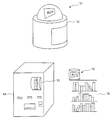
- FIG. 1 shows several operating environments for installation of the volumetric display of the invention
- FIG. 2 shows a block diagram of the volumetric display of FIG. 1
- FIG. 3 shows the illumination controller and signal generator of FIG. 2
- FIG. 4 shows a specific implementation of the illumination controller and signal generator of FIG. 2;
- FIG. 5 shows examples of the manner in which the volumetric display interleaves two signals to generate a sequence of illumination events.
- a volumetric display 10 according to the invention can be advantageously displayed for public view in a number of advertising environments, several of which are illustrated in FIG. 1 .
- the volumetric display 10 can be positioned atop a vendor's kiosk 12 , on the front surface or in the interior of a vending machine 14 , or on a store shelf display 16 .
- the volumetric display 10 can be seen by one or more viewers from a variety of angles.
- the volumetric display 10 includes a moving object 18 coupled to a motor 20 .
- the moving object 18 typically has an advertising messages on the front and back of a rectangular surface.
- the surface of the moving object 18 which is typically 6′′ (152.4 mm) across and 4′′ (101.6 mm) high, is made of ⁇ fraction (1/16) ⁇ ′′(1.6 mm) thick Plexiglas.
- the moving object 18 can rectangle or other essentially two-dimensional shape.
- the moving object 18 can be a curve in three dimensions, such as a helix, or a three-dimensional solid, such as a soda can.
- the volumetric display 10 optionally includes a transparent display cover 22 enclosing the moving object 18 .
- the display cover 22 is preferably coated, or otherwise configured to increase the perceived brightness of the moving object 18 .
- a one-way mirror, one-way glass, wavelength-specific filters, or a system of polarizers can be used for a display cover 22 .
- the motor 20 coupled to the moving object 18 causes the moving object 18 to sweep out a display volume 23 by undergoing rapid, periodic motion.
- the moving object 18 undergoes rapid rotation of at least 10 revolutions per second, or ideally 20 revolutions per second.
- FIG. 2 shows a moving object 18 undergoing rotation
- the coupling between the motor 20 and the moving object 18 can also result in translation, vibration, or oscillation of the moving object 18 , all of which can sweep out a display volume 23 as shown in FIG. 2 .
- the resulting motion of the moving object 18 can also be a combination of any of the foregoing types of motion in any direction.
- a first sensor 24 coupled to the moving object 18 provides information concerning the rotational frequency and, optionally, the position of the moving object 18 , to a signal generator 25 .
- information concerning the position of the moving object 18 is embodied in the mechanical phase of the moving object 18 .
- the signal generator 25 In response to information provided by the first sensor 24 , the signal generator 25 generates at least two signals. These signals are provided to a programmable illumination controller 26 that generates a sequence of illumination events by selectively sampling the signals and selecting particular samples with which to drive a strobe unit 28 .
- a strobe unit 28 is any unit that illuminates the moving object 18 with a sequence of light pulses, each of which is sufficiently short, relative to the motion of the moving object 18 , to make the moving object appear to be stationary for the duration of the pulse.
- a strobe unit 28 can include flash lamps as well as LEDs and other light sources that emit short pulses. However, for slowly moving objects, the strobe unit 28 can be a conventional incandescent light controlled by a switch.
- the illumination controller 26 can generate eye-catching visual effects. For example, if the moving object 18 rotates at a frequency of at least 10 rps, the strobe unit 28 can illuminate the moving object 18 in a manner that: freezes the apparent position of the moving object 18 ; makes the moving object 18 appear to move at varying speeds in either direction; makes the element jump from one spatial orientation to another; makes the moving object 18 appear to have multiple elements which are rotating in an overlapping manner in the same, and or different, directions.
- the volumetric display 10 exploits temporal aliasing by using a programmable stroboscope to create an eye-catching three-dimensional display.
- FIG. 3 shows an embodiment in which the signal generator 25 receives, from the first sensor 24 , a periodic signal that corresponds to the frequency of the motor 20 . In most cases, this frequency is approximately 400 Hz.
- the first sensor 24 can also provide information on the position of the moving object 18 directly to the illumination controller 26 . In the case of rotational motion of the moving object 18 , this position corresponds to a mechanical phase. However, it is possible to create interesting effects even without a signal, such as mechanical phase, that indicates the position of the moving object 18 .
- independent oscillators 34 , 36 (such as simple 555 timers) create short pulses at frequencies close to the 20 Hz signal, such as 19 Hz and 21 Hz.
- the signal from the divide-by-N block 32 (the 20 Hz signal) and the signals from the oscillators 34 , 36 (the 19 Hz and 21 Hz signals) are provided to the illumination controller 26 .
- a first switch 37 a samples the signal generated by the divide-by-N block 32 .
- second and third switches 37 b-c sample the signals generated by the first and second oscillators 34 , 36 . These samples become inputs to an OR gate 38 .
- the output of the OR gate 38 is a single stream of illumination events generated by selectively sampling the signals generated by the divide-by-N block 32 , the first oscillator 34 , and the second oscillator 36 .
- the illumination controller 26 thus functions as a multiplexer that selects from three signal streams to form one output stream of illumination events.
- the operation of the switches 37 a-c and of the input switch 30 are under the control of a processor, such as a programmable logic array 44 or simple microcontroller, operating in conjunction with a low-frequency (typically 0.3 Hz) timer 46 to indicate a change-of-state.
- a processor such as a programmable logic array 44 or simple microcontroller, operating in conjunction with a low-frequency (typically 0.3 Hz) timer 46 to indicate a change-of-state.
- the programmable logic array 44 causes the illumination controller 26 to illuminate the moving object 18 in a manner that creates various eye-catching patterns.
- the illumination unit 28 includes 10 super-bright LEDs 40 controlled by a BJT switching circuit 42 .
- the output of the OR gate 38 is connected to the base terminal of a BJT so that when the output of the OR gate 38 is high, current from the emitter terminal of the BJT is provided to the LEDs 40 .
- other light sources such as, bright white-light flashlamps, can also be used.
- FIG. 4 is a schematic of an illumination unit 28 under manual (pushbutton and SPST switch) mode control.
- a viewer can push the input switch 30 to change the phase of the signal provided at the output of the divide-by-N block 32 .
- the illumination unit 28 includes several transistors 42 , each one driving a parallel pair of LEDs 40 .
- Each transistor 42 has a base driven by an output of a 3-input OR gate 32 formed by connecting the output of a first two-input OR gate to the input of a second two-input OR gate.
- the outputs of the first and second oscillators 34 , 36 are passed through first and second high-pass filters 41 , 43 before being provided to the OR gate 32 by way of the first and second switches 37 b , 37 c.
- the volumetric display 10 can include a second sensor 48 , for example a motion sensor, to cause the volumetric display 10 to be responsive to the presence or motion of a viewer.
- the second sensor 48 can detect the presence of a viewer and/or the position of the position of one or more viewers. The second sensor 48 can then provide that information to the illumination controller 26 as shown in FIG. 2 .
- the programmable logic array 44 can be programmed to cause the display 10 to interact with the viewer.
- the first sensor 24 provides an input signal having a frequency Nf as shown in FIG. 3 . If the input switch 30 is closed, the input signal passes through the divide-by-N block 32 . The corresponding output of the divide-by-N block 32 is a first signal having a frequency f. If the first switch 37 a is closed, this first signal causes the OR gate 38 to generate a series of output pulses at a frequency f. This series of output pulses causes the illumination unit 28 to illuminate the moving object 18 with periodic light pulses at a frequency of f. If the moving object 18 rotates at a frequency that is an integer multiple of f, the moving object 18 will appear to be standing still.
- phase of the signal provided at the output of the divide-by-N block 32 will change relative to the mechanical phase of the moving object 18 . This will cause a discontinuous phase change in the output of the OR gate 38 driving the strobe unit 18 . As a result of this phase change, the moving object 18 will appear to instantaneously shift from a first spatial orientation to a second spatial orientation.
- the illumination controller 26 can be configured to cause the moving display 18 to shift from a first spatial orientation to a random second spatial orientation by randomly opening and closing the switch 37 a .
- the shift to a random second spatial orientation can be achieved by inviting a viewer to press the input switch 30 .
- the discontinuous shift from the first spatial orientation to the second spatial orientation be coordinated with the motion of the moving object 18 .
- a moving object 18 can have several faces, each of which has a different image.
- the orientation of the moving display 18 can then be controlled to give the effect of animating those images.
- the display 10 is equipped with the optional second sensor 48 as described above, then information concerning the presence and/or position of the viewer will be available. This allows the illumination controller to select the second spatial orientation on the basis of the viewer's activities, thereby permitting the wireless interaction of the moving object 18 with the viewer. For example, the viewing angle for the advertising message on the moving object 18 can be continuously adjusted to follow the viewer as the viewer moves around the display. Alternatively, the display 10 can be activated upon the approach of a viewer to attract the viewer's attention and then deactivated upon the viewer's departure to avoid premature wear and excessive power usage.
- the input switch 30 and the divide-by-N block 32 thus cooperate to generate two signals.
- the first signal is a first pulse train having a frequency f and the signal is a second pulse train having the same frequency f but a different phase. These two signals can be temporally interleaved by periodically operating the input switch 30 .
- the two temporally interleaved signals are then provided to the illumination controller 26 .
- the programmable logic array 44 samples this stream of two temporally interleaved signals and provides those samples to the OR gate 38 .
- the sample provided to the OR gate 38 can arise from either the first signal or the second signal.
- the OR gate 38 In response to the sample provided at its input, the OR gate 38 generates a stream of pulses, each of which defines an illumination event that originates from either the first signal or the second signal.
- the first oscillator 34 generates a first pulse train at a frequency f+df 1 that is slightly higher than the frequency output by the divide-by-N block 32 .
- This first pulse train thus forms the second signal of the signal generator 25 , the first signal being the output of the divide-by-N block 32 .
- the programmable logic array 44 selectively passes or withholds this second signal from the OR gate 38 by selectively operating the switch 37 b . This results in the generation of a pulse train by the OR gate 38 , each of the pulses being an illumination event arising from either the first signal, provided by the divide-by-N block 32 , or from the second signal, provided by the first oscillator 34 .
- the first oscillator 34 and the divide-by-N block 32 can cooperate to generate a three-dimensional display in which the moving object 18 appears to rotate simultaneously in two directions at two different angular velocities.
- the first signal can illuminate the moving object 18 at a frequency slightly lower than the rotational frequency, thus generating the effect of a moving object 18 slowly rotating in a first direction.
- the second signal can illuminate the moving object 18 at a frequency slightly higher than the rotational frequency, in which case the moving object 18 will appear to slowly rotate in a second direction opposite the first direction.
- the second oscillator 36 generates a second pulse train at a frequency f ⁇ df 2 slightly lower than the frequency output by the divide-by-N block 32 . Note that the frequency offsets df 1 and df 2 need not be identical.
- This second oscillator 36 operates in a manner identical to the first oscillator 34 as described above.
- This second oscillator 36 together with optional additional oscillators operating in the same manner, can further enhance the visual display by generating additional signals having frequencies that differ from the first and second signal.
- FIG. 5 illustrates the manner in which the OR gate 38 interleaves pulse trains having different frequencies to form a sequence of illumination events.
- the uppermost graph shows a first pulse train at a frequency f as generated by the divide-by-N block 32 .
- the second and third graphs show second and third pulse trains at slightly higher (f+df 1 ) and slightly lower (f ⁇ df 2 ) frequencies as generated by the first and second oscillators 34 , 36 respectively.
- these three pulse trains are interleaved, as shown in the bottom graph of FIG. 5, to form a sequence of illumination events.
- the illumination controller 26 can further manipulate the sequence of illumination events.
- the second switch 37 b could be controlled so as to sample only every other pulse in the second pulse train, thereby effectively halving its frequency. This can result in sudden, and hence eye-catching changes in the appearance of the moving object 18 .
Abstract
Description
Claims (26)
Priority Applications (1)
| Application Number | Priority Date | Filing Date | Title |
|---|---|---|---|
| US09/598,275 US6512498B1 (en) | 1999-06-21 | 2000-06-19 | Volumetric stroboscopic display |
Applications Claiming Priority (2)
| Application Number | Priority Date | Filing Date | Title |
|---|---|---|---|
| US14024399P | 1999-06-21 | 1999-06-21 | |
| US09/598,275 US6512498B1 (en) | 1999-06-21 | 2000-06-19 | Volumetric stroboscopic display |
Publications (1)
| Publication Number | Publication Date |
|---|---|
| US6512498B1 true US6512498B1 (en) | 2003-01-28 |
Family
ID=22490361
Family Applications (1)
| Application Number | Title | Priority Date | Filing Date |
|---|---|---|---|
| US09/598,275 Expired - Fee Related US6512498B1 (en) | 1999-06-21 | 2000-06-19 | Volumetric stroboscopic display |
Country Status (3)
| Country | Link |
|---|---|
| US (1) | US6512498B1 (en) |
| AU (1) | AU6405800A (en) |
| WO (1) | WO2000079509A1 (en) |
Cited By (14)
| Publication number | Priority date | Publication date | Assignee | Title |
|---|---|---|---|---|
| US20020063679A1 (en) * | 2000-11-29 | 2002-05-30 | Goodwin John C. | Method of displaying information by a network kiosk |
| US20030142092A1 (en) * | 2002-01-25 | 2003-07-31 | Silicon Graphics, Inc. | Graphical user interface widgets viewable and readable from multiple viewpoints in a volumetric display |
| US20030142144A1 (en) * | 2002-01-25 | 2003-07-31 | Silicon Graphics, Inc. | Techniques for pointing to locations within a volumetric display |
| US20040001112A1 (en) * | 2002-01-25 | 2004-01-01 | Silicon Graphics, Inc. | Volume management system for volumetric displays |
| US20040001111A1 (en) * | 2002-06-28 | 2004-01-01 | Silicon Graphics, Inc. | Widgets displayed and operable on a surface of a volumetric display enclosure |
| US20040001075A1 (en) * | 2002-06-28 | 2004-01-01 | Silicon Graphics, Inc. | System for physical rotation of volumetric display enclosures to facilitate viewing |
| US20040212589A1 (en) * | 2003-04-24 | 2004-10-28 | Hall Deirdre M. | System and method for fusing and displaying multiple degree of freedom positional input data from multiple input sources |
| US20050230641A1 (en) * | 2004-04-05 | 2005-10-20 | Won Chun | Data processing for three-dimensional displays |
| US20060114172A1 (en) * | 2004-11-26 | 2006-06-01 | Giotti, Inc. | Method and apparatus for LED based modular display |
| US20060166727A1 (en) * | 2005-01-24 | 2006-07-27 | Wms Gaming Inc. | Gaming machine with proximity-sensitive input device |
| US20070118593A1 (en) * | 2004-07-26 | 2007-05-24 | Shiraz Shivji | Positioning system and method for LED display |
| US20080194930A1 (en) * | 2007-02-09 | 2008-08-14 | Harris Melvyn L | Infrared-visible needle |
| US20100039445A1 (en) * | 2008-08-14 | 2010-02-18 | Abb Oy | Displaying information on moving objects, and frequency converter |
| US20140015867A1 (en) * | 2012-07-13 | 2014-01-16 | Chengdu Boe Optoelectronics Technology Co., Ltd. | Spatial Stereoscopic Display Device And Operating Method Thereof |
Families Citing this family (1)
| Publication number | Priority date | Publication date | Assignee | Title |
|---|---|---|---|---|
| US20010045920A1 (en) * | 2000-04-06 | 2001-11-29 | Hall Deirdre M. | Projection screen for multiplanar volumetric display |
Citations (13)
| Publication number | Priority date | Publication date | Assignee | Title |
|---|---|---|---|---|
| US3140415A (en) | 1960-06-16 | 1964-07-07 | Hughes Aircraft Co | Three-dimensional display cathode ray tube |
| US4319805A (en) | 1979-02-06 | 1982-03-16 | Pierre Nicolas | Rotary screen for receiving optical images particularly advertising images |
| US4689604A (en) | 1983-03-03 | 1987-08-25 | S-V Development Ltd. | Moving visual display apparatus |
| US4983031A (en) | 1988-07-13 | 1991-01-08 | Solomon Dennis J | Three-dimensional volumetric display system |
| US5042909A (en) | 1987-10-07 | 1991-08-27 | Texas Instruments Incorporated | Real time three dimensional display with angled rotating screen and method |
| US5479153A (en) | 1993-10-26 | 1995-12-26 | Hankscraft Motors, Inc. | Method and apparatus for displaying an object |
| US5717416A (en) | 1995-04-11 | 1998-02-10 | The University Of Kansas | Three-dimensional display apparatus |
| US5813742A (en) * | 1996-04-22 | 1998-09-29 | Hughes Electronics | Layered display system and method for volumetric presentation |
| US5854613A (en) | 1994-03-16 | 1998-12-29 | The United Sates Of America As Represented By The Secretary Of The Navy | Laser based 3D volumetric display system |
| US5945966A (en) | 1996-10-02 | 1999-08-31 | The United States Of America As Represented By The Secretary Of The Navy | Computer program for a three-dimensional volumetric display |
| US6052100A (en) * | 1994-03-16 | 2000-04-18 | The United States Of America Represented By The Secertary Of The Navy | Computer controlled three-dimensional volumetric display |
| US6177913B1 (en) * | 1998-04-23 | 2001-01-23 | The United States Of America As Represented By The Secretary Of The Navy | Volumetric display |
| US6208318B1 (en) * | 1993-06-24 | 2001-03-27 | Raytheon Company | System and method for high resolution volume display using a planar array |
-
2000
- 2000-06-19 US US09/598,275 patent/US6512498B1/en not_active Expired - Fee Related
- 2000-06-20 AU AU64058/00A patent/AU6405800A/en not_active Abandoned
- 2000-06-20 WO PCT/US2000/040256 patent/WO2000079509A1/en active Application Filing
Patent Citations (13)
| Publication number | Priority date | Publication date | Assignee | Title |
|---|---|---|---|---|
| US3140415A (en) | 1960-06-16 | 1964-07-07 | Hughes Aircraft Co | Three-dimensional display cathode ray tube |
| US4319805A (en) | 1979-02-06 | 1982-03-16 | Pierre Nicolas | Rotary screen for receiving optical images particularly advertising images |
| US4689604A (en) | 1983-03-03 | 1987-08-25 | S-V Development Ltd. | Moving visual display apparatus |
| US5042909A (en) | 1987-10-07 | 1991-08-27 | Texas Instruments Incorporated | Real time three dimensional display with angled rotating screen and method |
| US4983031A (en) | 1988-07-13 | 1991-01-08 | Solomon Dennis J | Three-dimensional volumetric display system |
| US6208318B1 (en) * | 1993-06-24 | 2001-03-27 | Raytheon Company | System and method for high resolution volume display using a planar array |
| US5479153A (en) | 1993-10-26 | 1995-12-26 | Hankscraft Motors, Inc. | Method and apparatus for displaying an object |
| US6052100A (en) * | 1994-03-16 | 2000-04-18 | The United States Of America Represented By The Secertary Of The Navy | Computer controlled three-dimensional volumetric display |
| US5854613A (en) | 1994-03-16 | 1998-12-29 | The United Sates Of America As Represented By The Secretary Of The Navy | Laser based 3D volumetric display system |
| US5717416A (en) | 1995-04-11 | 1998-02-10 | The University Of Kansas | Three-dimensional display apparatus |
| US5813742A (en) * | 1996-04-22 | 1998-09-29 | Hughes Electronics | Layered display system and method for volumetric presentation |
| US5945966A (en) | 1996-10-02 | 1999-08-31 | The United States Of America As Represented By The Secretary Of The Navy | Computer program for a three-dimensional volumetric display |
| US6177913B1 (en) * | 1998-04-23 | 2001-01-23 | The United States Of America As Represented By The Secretary Of The Navy | Volumetric display |
Cited By (32)
| Publication number | Priority date | Publication date | Assignee | Title |
|---|---|---|---|---|
| US20020063679A1 (en) * | 2000-11-29 | 2002-05-30 | Goodwin John C. | Method of displaying information by a network kiosk |
| US7675503B2 (en) * | 2000-11-29 | 2010-03-09 | Ncr Corporation | Method of displaying information by a network kiosk |
| US7205991B2 (en) * | 2002-01-25 | 2007-04-17 | Autodesk, Inc. | Graphical user interface widgets viewable and readable from multiple viewpoints in a volumetric display |
| US7324085B2 (en) | 2002-01-25 | 2008-01-29 | Autodesk, Inc. | Techniques for pointing to locations within a volumetric display |
| US7528823B2 (en) | 2002-01-25 | 2009-05-05 | Autodesk, Inc. | Techniques for pointing to locations within a volumetric display |
| US7701441B2 (en) | 2002-01-25 | 2010-04-20 | Autodesk, Inc. | Techniques for pointing to locations within a volumetric display |
| US20080036738A1 (en) * | 2002-01-25 | 2008-02-14 | Ravin Balakrishnan | Techniques for pointing to locations within a volumetric display |
| US20030142092A1 (en) * | 2002-01-25 | 2003-07-31 | Silicon Graphics, Inc. | Graphical user interface widgets viewable and readable from multiple viewpoints in a volumetric display |
| US20050275628A1 (en) * | 2002-01-25 | 2005-12-15 | Alias Systems Corp. | System for physical rotation of volumetric display enclosures to facilitate viewing |
| US20060077212A1 (en) * | 2002-01-25 | 2006-04-13 | Alias Systems Corp. | Graphical user interface widgets viewable and readable from multiple viewpoints in a volumetric display |
| US20040001112A1 (en) * | 2002-01-25 | 2004-01-01 | Silicon Graphics, Inc. | Volume management system for volumetric displays |
| US20030142144A1 (en) * | 2002-01-25 | 2003-07-31 | Silicon Graphics, Inc. | Techniques for pointing to locations within a volumetric display |
| US7724251B2 (en) * | 2002-01-25 | 2010-05-25 | Autodesk, Inc. | System for physical rotation of volumetric display enclosures to facilitate viewing |
| US7839400B2 (en) | 2002-01-25 | 2010-11-23 | Autodesk, Inc. | Volume management system for volumetric displays |
| US7138997B2 (en) | 2002-06-28 | 2006-11-21 | Autodesk, Inc. | System for physical rotation of volumetric display enclosures to facilitate viewing |
| US7986318B2 (en) | 2002-06-28 | 2011-07-26 | Autodesk, Inc. | Volume management system for volumetric displays |
| US20060125822A1 (en) * | 2002-06-28 | 2006-06-15 | Alias Systems Corp. | Volume management system for volumetric displays |
| US20040001111A1 (en) * | 2002-06-28 | 2004-01-01 | Silicon Graphics, Inc. | Widgets displayed and operable on a surface of a volumetric display enclosure |
| US20040001075A1 (en) * | 2002-06-28 | 2004-01-01 | Silicon Graphics, Inc. | System for physical rotation of volumetric display enclosures to facilitate viewing |
| US7554541B2 (en) | 2002-06-28 | 2009-06-30 | Autodesk, Inc. | Widgets displayed and operable on a surface of a volumetric display enclosure |
| US20040212589A1 (en) * | 2003-04-24 | 2004-10-28 | Hall Deirdre M. | System and method for fusing and displaying multiple degree of freedom positional input data from multiple input sources |
| US20050230641A1 (en) * | 2004-04-05 | 2005-10-20 | Won Chun | Data processing for three-dimensional displays |
| US7525541B2 (en) | 2004-04-05 | 2009-04-28 | Actuality Systems, Inc. | Data processing for three-dimensional displays |
| US20070118593A1 (en) * | 2004-07-26 | 2007-05-24 | Shiraz Shivji | Positioning system and method for LED display |
| US20060114172A1 (en) * | 2004-11-26 | 2006-06-01 | Giotti, Inc. | Method and apparatus for LED based modular display |
| WO2006058196A3 (en) * | 2004-11-26 | 2007-02-08 | Giotti Inc | Method and apparatus for led based modular display |
| WO2006058196A2 (en) * | 2004-11-26 | 2006-06-01 | Giotti, Inc. | Method and apparatus for led based modular display |
| US20060166727A1 (en) * | 2005-01-24 | 2006-07-27 | Wms Gaming Inc. | Gaming machine with proximity-sensitive input device |
| US20080194930A1 (en) * | 2007-02-09 | 2008-08-14 | Harris Melvyn L | Infrared-visible needle |
| US20100039445A1 (en) * | 2008-08-14 | 2010-02-18 | Abb Oy | Displaying information on moving objects, and frequency converter |
| US9323068B2 (en) * | 2012-07-13 | 2016-04-26 | Chengdu Boe Optoelectronics Technology Co., Ltd. | Spatial stereoscopic display device and operating method thereof |
| US20140015867A1 (en) * | 2012-07-13 | 2014-01-16 | Chengdu Boe Optoelectronics Technology Co., Ltd. | Spatial Stereoscopic Display Device And Operating Method Thereof |
Also Published As
| Publication number | Publication date |
|---|---|
| WO2000079509A9 (en) | 2002-08-01 |
| AU6405800A (en) | 2001-01-09 |
| WO2000079509A1 (en) | 2000-12-28 |
Similar Documents
| Publication | Publication Date | Title |
|---|---|---|
| US6512498B1 (en) | Volumetric stroboscopic display | |
| US5954414A (en) | Moving screen projection technique for volumetric three-dimensional display | |
| EP1504596B1 (en) | High-resolution image projection | |
| US8194118B2 (en) | Performance display system | |
| KR20050118510A (en) | Apparatus for improving resolution of display apparatus and method thereof | |
| JP4462303B2 (en) | Image display device | |
| CN101511036A (en) | Colourful panorama visual field three-dimensional display device based on LED | |
| US20080129963A1 (en) | Animation by selected strobing of rotating images | |
| WO1999008257A1 (en) | Liquid crystal controlled display apparatus | |
| EP0120929A1 (en) | Method and apparatus for animating illuminated signs and displays. | |
| US5408389A (en) | Interrupted light source | |
| JP2004279888A (en) | Display device | |
| JP2003161897A (en) | Optical path deflect element and image display | |
| TWI591381B (en) | Projection display system and method with multiple, convertible display modes | |
| JP2007017664A (en) | Screen, projector system, rear projector | |
| JP2008020636A (en) | Light source device and video display apparatus | |
| US2132473A (en) | Mirror sign and electric circuits therefor | |
| US2995981A (en) | Apparatus for displaying vectographic prints | |
| KR100366365B1 (en) | A device for displaying multiple sterographic images in sequence | |
| KR100191435B1 (en) | A tower of advertisement for simply displaying moving image | |
| US5117307A (en) | Rotating wheel image maker | |
| JPH0434543A (en) | Stereoscopic video producing device | |
| RU2159962C1 (en) | Rotating information display | |
| KR200183284Y1 (en) | A device for displaying multiple sterographic images in sequence | |
| JPH07333546A (en) | Stereoscopic image display device |
Legal Events
| Date | Code | Title | Description |
|---|---|---|---|
| AS | Assignment |
Owner name: ACTUALITY SYSTEMS, INC., MASSACHUSETTS Free format text: ASSIGNMENT OF ASSIGNORS INTEREST;ASSIGNORS:FAVALORA, GREGG E.;SAMUEL, SHAWN T.;REEL/FRAME:011743/0097;SIGNING DATES FROM 20000608 TO 20000621 |
|
| FPAY | Fee payment |
Year of fee payment: 4 |
|
| FEPP | Fee payment procedure |
Free format text: PAYOR NUMBER ASSIGNED (ORIGINAL EVENT CODE: ASPN); ENTITY STATUS OF PATENT OWNER: SMALL ENTITY |
|
| AS | Assignment |
Owner name: ELLIS AMALGAMATED LLC, D/B/A OPTICS FOR HIRE, MASS Free format text: ASSIGNMENT OF ASSIGNORS INTEREST;ASSIGNOR:ACTUALITY SYSTEMS, INC.;REEL/FRAME:023699/0897 Effective date: 20091228 |
|
| REMI | Maintenance fee reminder mailed | ||
| FEPP | Fee payment procedure |
Free format text: PAYER NUMBER DE-ASSIGNED (ORIGINAL EVENT CODE: RMPN); ENTITY STATUS OF PATENT OWNER: SMALL ENTITY Free format text: PAYOR NUMBER ASSIGNED (ORIGINAL EVENT CODE: ASPN); ENTITY STATUS OF PATENT OWNER: SMALL ENTITY |
|
| FPAY | Fee payment |
Year of fee payment: 8 |
|
| SULP | Surcharge for late payment |
Year of fee payment: 7 |
|
| AS | Assignment |
Owner name: ELLIS AMALGAMATED LLC, D/B/A OPTICS FOR HIRE, MASS Free format text: ASSIGNMENT OF ASSIGNORS INTEREST;ASSIGNOR:ACTUALITY SYSTEMS, INC.;REEL/FRAME:026988/0331 Effective date: 20091228 |
|
| AS | Assignment |
Owner name: PARELLEL CONSULTING LIMITED LIABILITY COMPANY, DEL Free format text: ASSIGNMENT OF ASSIGNORS INTEREST;ASSIGNOR:ELLIS AMALGAMATED LLC;REEL/FRAME:027225/0540 Effective date: 20110929 |
|
| REMI | Maintenance fee reminder mailed | ||
| LAPS | Lapse for failure to pay maintenance fees | ||
| STCH | Information on status: patent discontinuation |
Free format text: PATENT EXPIRED DUE TO NONPAYMENT OF MAINTENANCE FEES UNDER 37 CFR 1.362 |
|
| FP | Lapsed due to failure to pay maintenance fee |
Effective date: 20150128 |