US6514137B1 - Modular clean room plenum - Google Patents
Modular clean room plenum Download PDFInfo
- Publication number
- US6514137B1 US6514137B1 US09/690,709 US69070900A US6514137B1 US 6514137 B1 US6514137 B1 US 6514137B1 US 69070900 A US69070900 A US 69070900A US 6514137 B1 US6514137 B1 US 6514137B1
- Authority
- US
- United States
- Prior art keywords
- clean room
- air
- modular
- plenum
- plenums
- Prior art date
- Legal status (The legal status is an assumption and is not a legal conclusion. Google has not performed a legal analysis and makes no representation as to the accuracy of the status listed.)
- Expired - Lifetime
Links
Images


Classifications
-
- F—MECHANICAL ENGINEERING; LIGHTING; HEATING; WEAPONS; BLASTING
- F24—HEATING; RANGES; VENTILATING
- F24F—AIR-CONDITIONING; AIR-HUMIDIFICATION; VENTILATION; USE OF AIR CURRENTS FOR SCREENING
- F24F3/00—Air-conditioning systems in which conditioned primary air is supplied from one or more central stations to distributing units in the rooms or spaces where it may receive secondary treatment; Apparatus specially designed for such systems
- F24F3/12—Air-conditioning systems in which conditioned primary air is supplied from one or more central stations to distributing units in the rooms or spaces where it may receive secondary treatment; Apparatus specially designed for such systems characterised by the treatment of the air otherwise than by heating and cooling
- F24F3/16—Air-conditioning systems in which conditioned primary air is supplied from one or more central stations to distributing units in the rooms or spaces where it may receive secondary treatment; Apparatus specially designed for such systems characterised by the treatment of the air otherwise than by heating and cooling by purification, e.g. by filtering; by sterilisation; by ozonisation
- F24F3/167—Clean rooms, i.e. enclosed spaces in which a uniform flow of filtered air is distributed
Definitions
- This invention relates to the construction of air delivery systems in clean rooms and, more particularly, to a modular clean room plenum for semiconductor manufacturing, aerospace, pharmaceutical and medical clean rooms and other applications where large volumes of particulate free, temperature and humidity controlled vertical laminar airflow are required.
- Clean room air delivery systems are generally designed to filter out dirt and dust particles of a very small size, correct the humidity and temperature of the air, and supply that air into the clean room in a laminar airflow pattern.
- the laminar airflow may be either vertically downward from the ceiling to the floor, horizontally from one side of the clean room space to the other, or horizontally across the clean room work surface, and then downward to the floor.
- the vertically downward airflow direction is the most common in the industry.
- the volume of air delivery to the clean room ranges from approximately 30 cubic feet per minute to 120 cubic feet per minute per square foot of clean room floor space. This volume compares to 1.0 to 1.5 cubic feet per minute per square foot of floor space in a typical office building.
- Such clean room air delivery systems are often used in semiconductor manufacturing clean rooms, but have numerous applications where a particulate-free, temperature and humidity controlled environment is required.
- FIG. 1 illustrates a conventional clean room and air barrier arrangement. Based on existing design principles, the normal sequence is to construct the building's foundations and shell 11 , including an extensive primary support structure 13 spanning the width and length of the clean room area using a minimum of intermediate support columns 12 .
- Primary support structure 13 may be constructed of steel trusses, steel space frames, or various types of concrete.
- a roofing system added to the top of the primary support structure 13 forms a primary air barrier 3 to contain air within the building.
- Secondary support structure 37 is attached to and supported by the bottom of the primary support structure 13 .
- Secondary support structure 37 will support a secondary air barrier 35 covering the entire clean room area.
- the purpose of secondary air barrier 35 is to separate the “conditioned” supply air from the “dirty” return air.
- the “conditioned” supply air becomes “dirty” as it passes through the clean room space 17 and picks up heat, humidity, and dirt particles from persons, products, and machinery in the clean room space 17 .
- the “conditioned” supply air may be above the secondary air barrier 35 with the “dirty” return air below the barrier 35 , or the “dirty” return air may be above the secondary air barrier 35 and the “conditioned” supply air below.
- Secondary air barrier 35 must be sufficiently strong to support the weight of workers who may have to enter the space above secondary air barrier 35 to conduct maintenance or modifications, and to support the entire underlying ceiling grid 39 and all of its components.
- a tertiary support system 45 is installed on the underside of the secondary air barrier 35 to support the ceiling grid 39 and its components.
- the secondary support structure 37 may also be required to support an automated material handling system 63 (a means of distributing product throughout the clean room) or other production equipment.
- the supports for such a material handling system 63 must penetrate the secondary air barrier 35 and are a source of air leaks, as well as being difficult to construct.
- the ceiling grid 39 which forms the tertiary air barrier comprises a sealed structural support system that may contain, but is not limited to, air filters, return air grilles, blank panels, and lights.
- the ceiling grid 39 also provides support for the fire sprinkler system.
- a piping system is added to the assembled ceiling grid 39 , a sprinkler main (not shown) is connected to the piping system, sprigs are installed, and sprinkler heads are connected to ceiling grid 39 . Electrical wiring and light fixtures are also connected to the ceiling grid 39 .
- the ceiling grid 39 has a grid of interconnected rails in a rectangular pattern with openings between the rails generally 2′ ⁇ 4′, in dimension. These rails have moat-like channels on each side, which form a continuous moat around all sides of the rectangular openings.
- All of the rectangular openings will be in-filled with, e.g., high efficiency particulate filters (filters may be of any type well known in the art, such as a HEPA or ULPA filters, similar to those manufactured by, e.g., Flanders or Filtra), blank panels, lights, sprinkler head panels, and return air grills.
- filters may be of any type well known in the art, such as a HEPA or ULPA filters, similar to those manufactured by, e.g., Flanders or Filtra
- blank panels e.g., lights, sprinkler head panels, and return air grills.
- the items installed in the ceiling grid 39 have downwardly depending flanges around their peripheral edges that fit into the moat-like channels of the grid 39 .
- a gel sealant e.g., BioMed 246 manufactured by Formula Brand Coatings & Products
- This sealed ceiling grid 39 forms the tertiary air barrier.
- other forms of sealants can be used to seal the ceiling grid.
- other types of ceiling grids 39 use T-shaped interconnecting rails and filters, blank panels, lights, sprinkler head panels, and return air grills with flat bottoms rather than downwardly depending flanges. These various panels are sealed into the grid system 39 using various forms of gaskets to prevent air leakage.
- transfer air ducts 9 are installed extending from the secondary air barrier 35 to the ceiling grid 39 .
- the transfer air ducts 9 may carry either “conditioned” supply air or “dirty” return air depending upon the air flow pattern of the design. If the “conditioned” supply air is above the secondary air barrier 35 , transfer air ducts 9 with balancing dampers 91 and flex connections 31 are installed from the secondary air barrier 35 down to each of the filters in the ceiling grid 39 . These transfer air ducts 9 will deliver “conditioned” supply air through the filters and into the clean room 17 . In this case, “dirty” return air passes through the return air grilles directly into the “dirty” return air plenum 41 below the secondary air barrier 35 . This embodiment is illustrated in FIG. 1 .
- the “conditioned” supply air passes directly through the filters into the clean room space 17 .
- the “dirty” return air must then be ducted from the return air grills 5 (FIG. 3) in the ceiling 39 up through the secondary air barrier 35 into the “dirty” return air plenum 41 .
- the “dirty” return air is taken through a recirculation air handling unit 21 , returned as “conditioned” supply air and delivered through the filters to the clean room space 17 .
- Recirculation air handling units 21 of this type are typically located outside the clean room space 17 .
- “conditioned” supply air may be circulated through a fan unit (not shown) located above the ceiling grid 39 and below the secondary air barrier 35 . These units are generally referred to as a fan filter units (FFU).
- FFU fan filter units
- Recirculation air handler (RAH) unit 21 takes air from return air plenum 41 in the direction indicated by RAH inlet airflow arrow 27 .
- the RAH unit 21 corrects the temperature and humidity of the air, and supplies it to air supply plenum 40 in the direction of conditioned supply arrow 15 at an increased air pressure.
- the supply air travels down through an array of transfer air ducts 9 , dampers 91 , and air filters 47 , into clean room 17 in a laminar airflow pattern.
- the laminar airflow travels downward as indicated by arrow 29 towards raised floor 18 .
- the air travels through raised floor 18 via air holes provided in the floor, passes through subfloor region 19 to return air chase 43 , up through ceiling grid 39 in the direction of arrow 16 and back into return air plenum 41 .
- return air plenum 41 return air from the clean room 17 is mixed with air from outside the building, provided by makeup air unit 23 .
- Makeup air unit 23 takes outside air, adjusts it for interior temperature and humidity requirements, filters it, and supplies the air through ductwork 51 to return air plenum 41 along the path illustrated by MAU airflow arrow 25 .
- the new air from makeup air unit 23 mixes with the return air from the clean room 17 and is processed by recirculation air handler 21 to be supplied back to clean room 17 , as described above.
- Design of the clean room 17 requires very specific and carefully controlled air velocities in a vertical airflow pattern.
- the air velocity must be within certain limits of the design velocities, usually 5% to 10% of design.
- the air velocity can be set and controlled by adjusting balancing dampers 91 located in the air supply to each of the air filters 47 in the ceiling grid 39 , and by adjusting the settings on the recirculation air handling unit 21 .
- the balancing dampers 91 may be located at the bottom end of the transfer air ducts 9 above the ceiling grid 39 and below the secondary air barrier 35 .
- Balancing typically requires a two-step process because the balancing damper 91 is in an inaccessible location when the ceiling grid 39 is completed.
- a preliminary balance is achieved by adjusting the balancing dampers 91 before the ceiling grid 39 is completed, followed by a final balance after completion of ceiling grid 39 .
- This process is time-consuming and interferes with the construction process, and can lead to certification delays if the preliminary balance was not accurate.
- the ceiling grid 39 will have to be opened and the balancing damper 91 adjusted properly. If the airflow requirements of the clean room 17 change, it usually is necessary to shut down the manufacturing operation so the ceiling grid 39 may be opened and the balancing dampers 91 accessed.
- Buildings housing clean rooms 17 typically require the construction to proceed in a set sequence. First the foundations are constructed, then the primary structural support 13 , followed by the roofing system. With the roofing system complete, construction of the clean room air distribution system may begin. First, the secondary support system 37 is installed, followed in sequence by the secondary air barrier 35 , the tertiary support system 45 and the ceiling grid system 39 . The final stage of the construction is the installation of the transfer air ducts 9 , the fire sprinkler system, the filters, blank panels, sprinkler head panels and return air grilles. Preliminary balancing of the dampers 91 must take place before the ceiling grid 39 is completed, followed by final balance after completion of the ceiling grid 39 .
- the space between the ceiling grid system 39 and the secondary air barrier 35 and the space between the secondary air barrier 35 and the roofing system must be protected from the effects of fire.
- the space above the secondary air barrier 35 is typically unoccupied, because it supports a major portion of the building, it therefore must be fire protected to meet safety codes.
- This fire protection is typically applied before the secondary air barrier 35 is installed.
- the clean room space 17 below the ceiling grid system 39 is generally considered by building codes to be an “occupied space”, therefore requiring application of stricter fire protection rules.
- the return air plenum area is generally protected by fire sprinkler risers, called “sprigs”, connected to the conventional fire sprinkler system serving the clean room space 17 . These sprigs are usually installed after the ceiling grid system is in place and before the filters, blank panels, sprinkler head panels and return air grilles are installed.
- the manufacturing process requires that the clean room space 17 be divided into separate and distinct zones, requiring a complete separation of the air streams from the primary air barrier 3 through the clean room subfloor 19 to avoid cross-contamination of the air between various processes.
- many buildings are constructed larger than current manufacturing space requirements, and the “future growth” areas must be separated from the utilized clean room space. In both cases, the separation is typically achieved using vertical barriers, referred to as “demising walls”.
- Demising walls are typically connected to the building structural system for support, and are constructed similar to a standard wall, using sheet rock, sheet metal or special clean room panels for the wall surface. This type of vertical barrier is labor intensive to construct and difficult to move if the demands of the manufacturing process require a change. Using existing clean room construction techniques, adjustments to the demising walls will incur substantial costs and usually disturb the existing manufacturing process.
- the plenum system based upon such a design should be easily modifiable with respect to area partitioning, clean room expansion, filter locations, blank panel locations, “dirty” air return locations, lighting locations and fire sprinkler layout.
- the plenum system should afford the ability to hang automatic material handling systems (AMHS) and other production equipment from the ceiling grid without having to penetrate the secondary air barrier to attach to the secondary support structure.
- the plenum system should reduce the time required to achieve the critical air balance requirements and make re-balancing relatively easy.
- the plenum system should also greatly reduce the hazards of working high above the clean room floor during installation and modification.
- a modular clean room plenum includes the secondary air barrier, the transfer air ducts, the ceiling grid system, the balancing dampers, the lighting, the fire sprinkler system, and the framework between the secondary air barrier and the ceiling grid in one modular component manufactured in a plant remote from the construction site.
- the rectangular modular clean room plenum is made up of a top surface forming the secondary air barrier, a bottom surface forming the ceiling grid system, and sides supporting the top and bottom surfaces.
- the modular clean room plenums are attached to the primary structural support system in whatever number and configuration are required by the clean room layout.
- the secondary support system and tertiary support system are eliminated or minimized because the modular clean room plenum is designed to be self-supporting from the primary support system.
- the modular clean room plenum also includes support for automatic material handling systems, fan filter units, and other equipment required by the manufacturing process.
- the air barrier and the ceiling layer are lifted into place simultaneously.
- the cost and time required for construction at the project site is significantly decreased because much of the high work required by current design principles is eliminated.
- the modular clean room plenums can be assembled away from the construction site in another manufacturing facility.
- the modules can be constructed in parallel with the construction of the building's primary support system and roofing system.
- the modules can then be shipped to the site for installation as soon as the roofing system is completed. Because the modules are constructed outside the clean room where clean room protocol is not required, the efficiency is increased and costs decreased.
- One embodiment of the present invention includes a balancing damper attached to the bottom of the transfer air duct inside the modular clean room plenum body.
- Another embodiment of the present invention includes a balancing damper attached to the top of the transfer air duct and located on top of the modular clean room plenum body.
- the modular plenum in accordance with the present invention also provides a modular sprinkler system comprising a distribution pipe, vertical sprigs, and sprinkler heads attached by flexible hoses.
- the modular clean room plenum in accordance with the present invention may also include a modular electrical system having electrical wiring and at least two junction boxes connected to the electrical wiring for connection with junction boxes of adjacent plenum bodies.
- This modifiable electrical system provides electricity to each plenum body and lighting in any required configuration. It also provides the ability to incorporate controls and variable speed drives for FFU's, AMHS and other equipment required by the manufacturing process.
- the modular clean room plenum system provides a base for constructing adaptable demising walls for smoke control, manufacturing zone separation or future build-out limits.
- This demising wall is constructed in such a way that future expansion of the clean room space is accomplished by attaching additional modules to the existing modules with the demising wall still in place. When construction of the additional space is complete, the demising wall can easily be moved to the new manufacturing zone limits.
- a method for installing a clean room plenum comprising the steps of assembling modular plenum bodies, installing a primary support structure in a building, and attaching the plenum bodies to the primary support structure.
- FIG. 1 illustrates a prior art clean room construction
- FIG. 2 illustrates clean room construction using the modular clean room plenum arrangement of the present invention.
- FIG. 3 illustrates a three-dimensional view of a modular clean room plenum in accordance with the present invention.
- FIG. 4 illustrates a cross-sectional view of a modular clean room plenum in accordance with the present invention.
- FIG. 5 illustrates a three-dimensional view of a modular clean room plenum used as a makeup air handling unit interface module in accordance with the present invention.
- FIG. 6 illustrates a three-dimensional view of a modular clean room plenum used as a recirculation air handling unit interface module in accordance with the present invention.
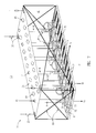
- FIG. 7 illustrates another embodiment of the present invention incorporating cross-bracing.
- FIG. 2 illustrates a clean room 17 using the modular clean room plenum arrangement of the present invention.
- Building shell 11 , primary support structure 13 , support columns 12 , and primary air barrier 3 are constructed essentially as described above with respect to FIG. 1 .
- the remaining structural features, comprising secondary air barrier 35 through to the tertiary air barrier are constructed as a collection of modular clean room plenums 1 .
- Each individual modular clean room plenum 1 provides in one preassembled unit the secondary air barrier 35 , secondary support system 37 , tertiary support system, transfer air ducts 9 , balancing dampers 91 , sprinkler main 73 , sprinkler heads 83 , sprigs 87 , ceiling grid 39 , and a lighting system.
- a plurality of modular clean room plenums 1 are attached to the primary support structure 13 and connected to each other to form a negative pressure plenum and complete construction of the clean room facility.
- FIG. 3 illustrates a three-dimensional view of a modular clean room plenum 1 in accordance with the present invention.
- the top and bottom surfaces and sides of modular clean room plenum 1 are substantially rectangular-shaped with the top surface forming secondary air barrier 35 and the bottom surface forming the ceiling grid 39 and the tertiary air barrier.
- the top of each modular clean room plenum 1 includes a plurality of openings 7 designed to receive transfer air ducts 9 . Each opening 7 is centered over one of the rectangular openings in the ceiling grid 39 below. Transfer air ducts 9 are inserted into all openings 7 that are above air filters 47 . The number and placement of air filters 47 are determined by the layout of the manufacturing equipment in the clean room.
- Each opening 7 not containing a transfer air duct 9 is provided with a cover plate 49 to protect workers from stepping through an uncovered opening 7 and to prevent unwanted air flow through secondary air barrier 35 .
- Openings in ceiling grid 39 contain either air filters 47 or blank panels 8 over the clean room area, and return air grills 5 over the return air chase 43 .
- Modular clean room plenum 1 is attached to primary support system 13 using support connections 33 .
- the embodiment shown in FIG. 3 includes four support connections 33 located at the top four corners of the modular clean room plenum 1 .
- different numbers of support connections 33 e.g., eight connections
- any other mounting system methods may be used to securely mount the modular clean room plenum 1 to the primary support system 13 .
- the airflow through the installed modular clean room plenums 1 is as follows. Conditioned supply air flows from supply air plenum 40 into transfer air duct 9 , through balancing damper 91 , duct flex connector 31 and air filter 47 , and into clean room 17 below. “Dirty” return air flows up from the return air chase 43 through return air grill 5 into return air plenum 41 , and back toward recirculation air handling unit 21 .
- modular clean room plenum 1 may be constructed in any size, some factors which would be considered in determining the dimensions of the modular clean room plenum 1 are the building structure, area, and airflow requirements. For example, in a building constructed with support columns spaced at 24 feet, the modular clean room plenum 1 shown in FIG. 3 may be constructed 24 feet long and 8 feet wide. The height of the modular clean room plenum 1 will be affected by various factors, including the amount of return airflow required for recirculation air handler 21 and the height of clean room 17 within the building shell 11 . It is understood that the invention is not limited by any specific dimensions of the modular clean room plenum 1 .
- FIG. 4 illustrates a cross-sectional view of the modular clean room plenum 1 .
- balancing dampers 91 are located inside return air plenum 41 towards the bottom of transfer air ducts 9 .
- the dampers 91 shown in FIG. 7 are adjusted from below the clean room ceiling after the air filters are installed but before the blank panels are installed.
- dampers 91 are attached to the top of opening 7 on the top of the modular clean room plenum 1 .
- dampers 91 are attached to the top of opening 7 on the top of the modular clean room plenum 1 .
- workers must enter the “clean” air region of the supply air plenum 40 in order to make adjustments to dampers 91 . Because this may interfere with the proper operation of the clean room system, the system is generally shut down when such adjustments are performed.
- the placement of the dampers 91 inside the “dirty” air region of return air plenum region 41 allows adjustment to the airflow through transfer air duct 9 and air filter 47 without interruption of the operation of the clean room.
- FIG. 4 Also shown in FIG. 4 is an embodiment of modular sprinkler system 70 which includes sprinkler main 73 that runs lengthwise through the modular clean room plenum 1 and is supported by supports 75 . At each end of sprinkler main 73 is a terminal 85 (FIG. 3) that can either be capped or be connected with a terminal 85 of an adjacently mounted modular clean room plenum 1 . This simplifies the process of providing water to all adjacent modular clean room plenums 1 .
- Flex hoses 77 Emerging from sprinkler main 73 at periodic points are flex hoses 77 .
- Flex hoses 77 may be made of a stainless steel flex and can be connected to any of a number of flex hose mounts 79 provided in ceiling grid 39 . These mounts can be provided in a regular pattern across the ceiling grid 39 .
- sprinkler heads (not shown) can be attached according to the sprinkler coverage requirements of the clean room floor. With this system, sprinkler heads can be provided in multiple configurations and can easily be modified as required by changing clean room layouts by simply moving the sprinkler heads to a new location and coupling a flex hose 77 to the appropriate flex hose mount 79 .
- the sprigs 87 in the modular clean room plenum 1 serve the space between the secondary air barrier 35 and the ceiling grid 39 , and the sprinkler heads on flexible hoses serve the clean room space 17 below the ceiling grid 39 .
- the modular clean room plenum's sprigs 87 are installed at the off-site manufacturing facility and are already in place when the module arrives at the job site.
- modular clean room plenum 1 may also provide supports for an automatic material handling system 63 .
- ceiling grid system 39 is adapted for connection with tracks or rails, as required by an automatic material handling system 63 , as is known in the art.
- the modular clean room plenum 1 provides sufficient support for the automatic material handling system 63 .
- the modular clean room plenum 1 can also include a modular electrical system to provide electricity for light fixtures on the clean room ceiling.
- electrical wiring can be integrated into the ceiling grid 39 during assembly off-site, eliminating the extra wiring step necessitated by prior art assembly processes.
- the electrical wiring may include junction boxes at two or more sides of the modular clean room plenum 1 for connection with junction boxes of adjacent modular clean room plenums 1 , and also provides connections for light fixtures to be mounted to the bottom of ceiling grid 39 . This allows electric power and lighting to be provided across the entire plenum quickly and easily.
- the electrical connections may be provided at multiple points across the ceiling grid 39 , thereby allowing for later changes in the light fixture placement.
- Wiring for computer network connections may also be provided in a similar fashion as the electrical wiring.
- the network wiring may be bundled with the electrical wiring, or may be provided separately.
- a number of advantages are achieved by using a modular clean room plenum 1 in accordance with the present invention.
- the present invention uses the present invention to manufacture all of the components of the modular clean room plenum 1 as described above, then delivered to the construction site as needed.
- pre-manufactured modular clean room plenums 1 are quickly and easily installed by simply lifting each pre-assembled modular clean room plenum 1 up to primary support structure 13 using a conventional lift device, and attaching the plenum 1 to the support structure 13 .
- the present invention reduces the time required for the second phase of construction from, e.g., 45 days in the example given above to 10 days.
- modular clean room plenum 1 Another advantage of the off-site manufacturing of the modular clean room plenum 1 is that cleanliness can be more easily controlled than at the construction site, thereby reducing the amount of time required to clean the area before gel is installed in the ceiling grid.
- Modular clean room plenum 1 may be constructed of powder-coated steel rather than rough steel to further assist in maintaining a clean installation.
- the modular clean room plenum system can also improve the process of installing the filters in the ceiling grid 39 .
- the secondary support structure 37 and ceiling grid 39 must be in place before the gel sealant could be poured into the ceiling grid vessels.
- the gel sealant, air filters, blank panels, and other ceiling grid elements can be installed in ceiling grid 39 while the modular clean room plenum 1 is resting on the clean room floor. Because this step is completed on the floor, rather than high up in the air, the work can be conducted with increased ease and safety over construction techniques used for the current design principles.
- the modular clean room plenum 1 is constructed with enough internal structural rigidity to safely hold its own weight, most of the secondary support system 37 used in the prior art to support the weight of the plenum structure is unnecessary when using the present invention, resulting in savings in cost of materials and construction time.
- the modular clean room plenum 1 also provides superior installation of demising walls.
- the modular clean room plenum 1 in accordance with the present invention may be open on each of its four sides to allow for airflow in any direction.
- Pre-shaped demising panels 4 constructed of powder-coated steel may be attached to any opening on any side of each modular clean room plenum 1 to prevent the flow of air through those openings of the modular clean room plenum 1 , thus enabling control of the direction of air flow. Because these openings are consistently sized on all modules, the demising plates can be moved to any opening in any module.
- demising panels 2 can be installed either before the modular clean room plenum 1 is connected to the primary support structure 13 , or at any later time when the manufacturing requirements change.
- the modular clean room plenum 1 can be used to easily expand the manufacturing area.
- the edge of the clean room floor space may be sealed by a wall which extends up to the bottom of the modular clean room plenum 1 and another wall which extends from the top of the modular clean room plenum 1 up to primary air barrier 3 .
- the module top forms a walkable surface for persons to work on while erecting the upper wall.
- the side of the modular clean room plenum 1 aligning with the edge of the clean room floor space is sealed using demising panels 4 as described above. In this fashion demising walls may be easily built following the outline of the modular clean room plenum 1 in any pattern that suits the needs of the manufacturing process.
- any number of additional modular clean room plenums 1 can be installed over the required expansion area.
- the demising panels 4 along the side adjacent to these newly installed modular clean room plenums 1 are removed, and additional demising panels 4 are added to the new modular clean room plenums 1 to complete the air seal.
- this additional construction requires only minimal cost and time.
- specialized plenum bodies may be constructed for installation in specific areas of the manufacturing floor.
- FIG. 5 shows another embodiment of a modular clean room plenum used as makeup air unit (MAU) interface module 2 a, which is installed directly beneath makeup air unit 23 .
- FIG. 2 shows an exemplary location of this module 2 a, but other embodiments may include different locations of makeup air unit 23 and makeup air unit interface module 2 a.
- MAU interface module 2 a is similar to the modular clean room plenum 1 described above, but is adapted for connection with a modular air unit 23 .
- Air enters return air plenum 41 of makeup air module 2 a from makeup air unit 23 via makeup air unit ductwork 59 . This airflow is shown by MAU airflow arrows 25 .
- FIG. 6 shows a modular clean room plenum used as a recirculation air handling unit (RAU) interface module 2 b, which is installed adjacent to recirculation air handling unit (RAU) 21 .
- FIG. 2 shows an exemplary location of this module 2 b.
- the recirculation air handling unit interface module 2 b includes an interface side 53 , which includes connection holes 61 used to attach interface side 53 to recirculating air handling unit 21 . Air flows in the direction of arrow 16 , into recirculation air handling unit 23 and back into supply air plenum 40 in the direction of MAU airflow arrow 25 . If vane axial fans or fan filter units are used to circulate the air in place of the RAU 21 , this RAU interface module 2 b may not be necessary.
- Makeup air unit 23 and recirculation air handling unit 21 are well known in the art and can, for example, be of the type manufactured by HUNTAIR of Tigard, Oreg.
- One embodiment of this invention uses vane axial fans rather than recirculation air handling units to circulate the air.
- the laminar airflow from the air ducts 9 passes through raised floor 18 and subfloor 19 into an area below subfloor 19 generally called the subfab (not shown).
- the “dirty” return air enters ductwork (not shown) and the vane axial fan (not shown) and is returned as conditioned supply air 15 in supply air plenum 40 .
- the vane axial fans may be located in fan deck 57 , in the subfab, or adjacent to corridor 55 .
- FFUs fan filter units
- FFUs may be located inside modular clean room plenum 1 in return air plenum 41 , or on top of modular clean room plenum 1 in supply air plenum 40 , and are supported by modular clean room plenum 1 .
- the FFU may be supported from the bottom surface of the modular clean room plenum 1 , and, if necessary, support rods may extended from the top surface of the modular clean room plenum 1 to the secondary support system.
- This method of support eliminates the need to penetrate the secondary air barrier with support members and therefore eliminates the possibility of air leaks inherent with current design principles.
- FIG. 7 shows another embodiment of the invention in which diagonal braces 93 are used to provide an additional structure for vertical and seismic support for the modular clean room plenum. All other elements of diagonal braced modular clean room plenum 2 c may be similar to modular clean room plenum 1 described in FIG. 3 above.
Abstract
Description
Claims (15)
Priority Applications (1)
| Application Number | Priority Date | Filing Date | Title |
|---|---|---|---|
| US09/690,709 US6514137B1 (en) | 1999-03-10 | 2000-10-16 | Modular clean room plenum |
Applications Claiming Priority (2)
| Application Number | Priority Date | Filing Date | Title |
|---|---|---|---|
| US09/267,123 US6132309A (en) | 1999-03-10 | 1999-03-10 | Modular clean room plenum |
| US09/690,709 US6514137B1 (en) | 1999-03-10 | 2000-10-16 | Modular clean room plenum |
Related Parent Applications (1)
| Application Number | Title | Priority Date | Filing Date |
|---|---|---|---|
| US09/267,123 Continuation US6132309A (en) | 1999-03-10 | 1999-03-10 | Modular clean room plenum |
Publications (1)
| Publication Number | Publication Date |
|---|---|
| US6514137B1 true US6514137B1 (en) | 2003-02-04 |
Family
ID=23017410
Family Applications (2)
| Application Number | Title | Priority Date | Filing Date |
|---|---|---|---|
| US09/267,123 Expired - Lifetime US6132309A (en) | 1999-03-10 | 1999-03-10 | Modular clean room plenum |
| US09/690,709 Expired - Lifetime US6514137B1 (en) | 1999-03-10 | 2000-10-16 | Modular clean room plenum |
Family Applications Before (1)
| Application Number | Title | Priority Date | Filing Date |
|---|---|---|---|
| US09/267,123 Expired - Lifetime US6132309A (en) | 1999-03-10 | 1999-03-10 | Modular clean room plenum |
Country Status (1)
| Country | Link |
|---|---|
| US (2) | US6132309A (en) |
Cited By (10)
| Publication number | Priority date | Publication date | Assignee | Title |
|---|---|---|---|---|
| US6670290B2 (en) * | 2000-10-16 | 2003-12-30 | Toshiro Kisakibaru | Manufacturing apparatus and manufacturing method for semiconductor device |
| WO2005076093A1 (en) * | 2004-02-03 | 2005-08-18 | Xcellerex, Llc | System and method for manufacturing |
| US20050272146A1 (en) * | 2004-06-04 | 2005-12-08 | Geoffrey Hodge | Disposable bioreactor systems and methods |
| US20080139865A1 (en) * | 2006-07-14 | 2008-06-12 | Xcellerex, Inc. | Environmental containment systems |
| US20090047893A1 (en) * | 2007-08-15 | 2009-02-19 | Larry Zimmerman | Building Plenum |
| US20090135667A1 (en) * | 2004-01-07 | 2009-05-28 | Terentiev Alexandre N | Mixing bag with integral sparger and sensor receiver |
| US20110097986A1 (en) * | 2009-10-22 | 2011-04-28 | Huntair, Inc. | Ceiling system with integrated equipment support structure |
| US20150011153A1 (en) * | 2012-02-10 | 2015-01-08 | Josef Oswald | Ventilation device for clean room applications |
| US9339026B2 (en) | 2012-06-14 | 2016-05-17 | Therapeutic Proteins International, LLC | Pneumatically agitated and aerated single-use bioreactor |
| DE102019121346A1 (en) * | 2019-07-16 | 2021-01-21 | Exyte Management GmbH | Ceiling module for setting up a clean room |
Families Citing this family (16)
| Publication number | Priority date | Publication date | Assignee | Title |
|---|---|---|---|---|
| US6574970B2 (en) | 2000-02-18 | 2003-06-10 | Toc Technology, Llc | Computer room air flow method and apparatus |
| US6557357B2 (en) | 2000-02-18 | 2003-05-06 | Toc Technology, Llc | Computer rack heat extraction device |
| US20050038553A1 (en) * | 2003-08-15 | 2005-02-17 | York International Corporation | System and method for managing the production of a custom designed product |
| US8147301B2 (en) * | 2006-01-19 | 2012-04-03 | Ray Ghattas | Air handling system for clean room |
| CA2750852A1 (en) * | 2008-12-23 | 2010-07-01 | Xoma, Technology Ltd. | Flexible manufacturing system |
| KR20120054634A (en) * | 2009-08-16 | 2012-05-30 | 지-콘, 엘엘씨 | Modular, self-contained, mobile clean room |
| US9795957B2 (en) | 2009-08-16 | 2017-10-24 | G-Con Manufacturing, Inc. | Modular, self-contained, mobile clean room |
| JP5777254B2 (en) * | 2012-01-31 | 2015-09-09 | 大成建設株式会社 | Air conditioning system and clean room |
| US9987651B2 (en) | 2014-08-06 | 2018-06-05 | Global Finishing Solutions Llc | Exhaust pit, system, and methods of using the same |
| US10071177B1 (en) | 2016-08-15 | 2018-09-11 | Synergy Med Global Design Solutions, Llc | Hospital and operating room designs and sterilization methods |
| US11224673B1 (en) | 2016-08-15 | 2022-01-18 | Synergy Med Global Design Solutions, Llc | Operating room intelligent platform and sterilization system |
| US11000613B1 (en) | 2016-08-15 | 2021-05-11 | Synergy Med Global Design Solutions, Llc | Transportable self-sterilizing clinical environment |
| US11408170B2 (en) * | 2019-02-06 | 2022-08-09 | Flexible OR Solutions LLC | Universal pre-fabricated operating room ceiling system |
| AU2020329233B2 (en) * | 2019-08-15 | 2022-07-07 | G-Con Manufacturing, Inc. | Removable panel roof for modular, self-contained, mobile clean room |
| US11492795B2 (en) | 2020-08-31 | 2022-11-08 | G-Con Manufacturing, Inc. | Ballroom-style cleanroom assembled from modular buildings |
| US20220170661A1 (en) * | 2020-12-01 | 2022-06-02 | AirPure Control Systems, LLC | Feedback-driven air treatment system for new and existing buildings |
Citations (8)
| Publication number | Priority date | Publication date | Assignee | Title |
|---|---|---|---|---|
| US4549472A (en) * | 1983-09-29 | 1985-10-29 | Hitachi Ltd. | Rearrangeable partial environmental control device |
| JPH03263534A (en) * | 1990-03-13 | 1991-11-25 | Hitachi Plant Eng & Constr Co Ltd | Air cleaning room |
| JPH03271645A (en) * | 1990-03-22 | 1991-12-03 | Hitachi Ltd | Air purifying system |
| JPH04306450A (en) * | 1991-04-03 | 1992-10-29 | Hitachi Plant Eng & Constr Co Ltd | Fan filter unit for clean room |
| US5462484A (en) * | 1991-07-08 | 1995-10-31 | Babcock Bsh Aktiengesellschaft Vormals Butner-Schilde-Haas Ag | Clean-room ceiling module |
| US5613759A (en) * | 1991-06-24 | 1997-03-25 | Brod & Mcclung-Pace Co. | Light and filter support structure |
| US6131077A (en) * | 1990-07-12 | 2000-10-10 | First Graphics, Inc. | Method and apparatus for designing and editing a distribution system for a building |
| US6158519A (en) * | 2000-01-18 | 2000-12-12 | Kretschmer; Alan P. | Fire suppression method and apparatus |
-
1999
- 1999-03-10 US US09/267,123 patent/US6132309A/en not_active Expired - Lifetime
-
2000
- 2000-10-16 US US09/690,709 patent/US6514137B1/en not_active Expired - Lifetime
Patent Citations (8)
| Publication number | Priority date | Publication date | Assignee | Title |
|---|---|---|---|---|
| US4549472A (en) * | 1983-09-29 | 1985-10-29 | Hitachi Ltd. | Rearrangeable partial environmental control device |
| JPH03263534A (en) * | 1990-03-13 | 1991-11-25 | Hitachi Plant Eng & Constr Co Ltd | Air cleaning room |
| JPH03271645A (en) * | 1990-03-22 | 1991-12-03 | Hitachi Ltd | Air purifying system |
| US6131077A (en) * | 1990-07-12 | 2000-10-10 | First Graphics, Inc. | Method and apparatus for designing and editing a distribution system for a building |
| JPH04306450A (en) * | 1991-04-03 | 1992-10-29 | Hitachi Plant Eng & Constr Co Ltd | Fan filter unit for clean room |
| US5613759A (en) * | 1991-06-24 | 1997-03-25 | Brod & Mcclung-Pace Co. | Light and filter support structure |
| US5462484A (en) * | 1991-07-08 | 1995-10-31 | Babcock Bsh Aktiengesellschaft Vormals Butner-Schilde-Haas Ag | Clean-room ceiling module |
| US6158519A (en) * | 2000-01-18 | 2000-12-12 | Kretschmer; Alan P. | Fire suppression method and apparatus |
Cited By (25)
| Publication number | Priority date | Publication date | Assignee | Title |
|---|---|---|---|---|
| US6670290B2 (en) * | 2000-10-16 | 2003-12-30 | Toshiro Kisakibaru | Manufacturing apparatus and manufacturing method for semiconductor device |
| US20040102058A1 (en) * | 2000-10-16 | 2004-05-27 | Toshiro Kisakibaru | Manufacturing apparatus and manufacturing method for semiconductor device |
| US6777355B2 (en) | 2000-10-16 | 2004-08-17 | Sony Corporation | Manufacturing apparatus and manufacturing method for semiconductor device |
| US20090135667A1 (en) * | 2004-01-07 | 2009-05-28 | Terentiev Alexandre N | Mixing bag with integral sparger and sensor receiver |
| US7992846B2 (en) | 2004-01-07 | 2011-08-09 | Atmi Packaging, Inc. | Mixing bag with integral sparger and sensor receiver |
| US8123199B2 (en) | 2004-01-07 | 2012-02-28 | Atmi Packaging, Inc. | Bioreactor |
| US20100197003A1 (en) * | 2004-01-07 | 2010-08-05 | Terentiev Alexandre N | Bioreactor |
| US9671798B2 (en) | 2004-02-03 | 2017-06-06 | Ge Healthcare Bio-Sciences Corp. | System and method for manufacturing |
| WO2005076093A1 (en) * | 2004-02-03 | 2005-08-18 | Xcellerex, Llc | System and method for manufacturing |
| US20050226794A1 (en) * | 2004-02-03 | 2005-10-13 | Geoffrey Hodge | System and method for manufacturing |
| CN102722105A (en) * | 2004-02-03 | 2012-10-10 | 艾克塞勒雷克斯公司 | System and method for manufacturing |
| US8298054B2 (en) | 2004-02-03 | 2012-10-30 | Xcellerex, Inc. | System and method for manufacturing |
| US7629167B2 (en) | 2004-06-04 | 2009-12-08 | Xcellerex, Inc. | Disposable bioreactor systems and methods |
| US20050272146A1 (en) * | 2004-06-04 | 2005-12-08 | Geoffrey Hodge | Disposable bioreactor systems and methods |
| US20080139865A1 (en) * | 2006-07-14 | 2008-06-12 | Xcellerex, Inc. | Environmental containment systems |
| US7819934B2 (en) | 2006-07-14 | 2010-10-26 | Xcellerex, Inc. | Environmental containment systems |
| US20090047893A1 (en) * | 2007-08-15 | 2009-02-19 | Larry Zimmerman | Building Plenum |
| US20110097986A1 (en) * | 2009-10-22 | 2011-04-28 | Huntair, Inc. | Ceiling system with integrated equipment support structure |
| US10371411B2 (en) * | 2009-10-22 | 2019-08-06 | Nortek Air Solutions, Llc | Ceiling system with integrated equipment support structure |
| US20150011153A1 (en) * | 2012-02-10 | 2015-01-08 | Josef Oswald | Ventilation device for clean room applications |
| US10113757B2 (en) * | 2012-02-10 | 2018-10-30 | R. Stahl Schaltgerate Gmbh | Ventilation device for clean room applications |
| US9339026B2 (en) | 2012-06-14 | 2016-05-17 | Therapeutic Proteins International, LLC | Pneumatically agitated and aerated single-use bioreactor |
| DE102019121346A1 (en) * | 2019-07-16 | 2021-01-21 | Exyte Management GmbH | Ceiling module for setting up a clean room |
| DE102019121346B4 (en) * | 2019-07-16 | 2021-07-01 | Exyte Management GmbH | Ceiling module for setting up a clean room |
| US11512467B2 (en) | 2019-07-16 | 2022-11-29 | Exyte Management GmbH | Ceiling module for the construction of a clean room |
Also Published As
| Publication number | Publication date |
|---|---|
| US6132309A (en) | 2000-10-17 |
Similar Documents
| Publication | Publication Date | Title |
|---|---|---|
| US6514137B1 (en) | Modular clean room plenum | |
| US4409889A (en) | Modular clean room | |
| EP0196333B1 (en) | Clean room constructing system | |
| US5344365A (en) | Integrated building and conveying structure for manufacturing under ultraclean conditions | |
| US5865674A (en) | Flush lighting system for cleanroom | |
| US5350336A (en) | Building and method for manufacture of integrated semiconductor circuit devices | |
| JPS6071830A (en) | Recombination type local environment control chamber | |
| IE74881B1 (en) | Filter/ventilator apparatus for use in clean rooms | |
| US6264550B1 (en) | Clean room and method of remodeling clean room | |
| KR101956642B1 (en) | Clean room air conditioning system and system ceiling for clean room | |
| JP5517755B2 (en) | Clean room partition unit and clean room partition method | |
| JP2011257018A (en) | Clean room facility and zoning method thereof | |
| US5069113A (en) | Stacked and cross-connected recirculating fans in a semiconductor manufacturing cleanroom | |
| CN1008397B (en) | Multi-purpose flexible clean room system | |
| JPH11200651A (en) | Clean room building and executing method therefor | |
| JP3787599B2 (en) | Clean room building | |
| JPS63201441A (en) | Clean room | |
| JP2580990B2 (en) | Cleanroom | |
| CN219840446U (en) | Assembled operating room | |
| CN112240073B (en) | Ceiling module for constructing clean room | |
| GB2136947A (en) | Spray Booth Air Handling Unit | |
| JPS62194140A (en) | Clean room | |
| JPS6266039A (en) | Facilities in cleaning work room | |
| JPH0623489B2 (en) | Clean room floor structure | |
| JPH074421Y2 (en) | Partition structure of air conditioner |
Legal Events
| Date | Code | Title | Description |
|---|---|---|---|
| STCF | Information on status: patent grant |
Free format text: PATENTED CASE |
|
| CC | Certificate of correction | ||
| FEPP | Fee payment procedure |
Free format text: PAT HOLDER NO LONGER CLAIMS SMALL ENTITY STATUS, ENTITY STATUS SET TO UNDISCOUNTED (ORIGINAL EVENT CODE: STOL); ENTITY STATUS OF PATENT OWNER: LARGE ENTITY |
|
| REFU | Refund |
Free format text: REFUND - SURCHARGE, PETITION TO ACCEPT PYMT AFTER EXP, UNINTENTIONAL (ORIGINAL EVENT CODE: R2551); ENTITY STATUS OF PATENT OWNER: LARGE ENTITY Free format text: REFUND - SURCHARGE FOR LATE PAYMENT, SMALL ENTITY (ORIGINAL EVENT CODE: R2554); ENTITY STATUS OF PATENT OWNER: LARGE ENTITY |
|
| AS | Assignment |
Owner name: UBS AG, STAMFORD BRANCH, AS ADMINISTRATIVE AGENT, Free format text: SECURITY AGREEMENT;ASSIGNORS:CLEANPAK INTERNATIONAL, INC.;HUNTAIR, INC.;SIGNING DATES FROM 20060426 TO 20060427;REEL/FRAME:017586/0137 Owner name: UBS AG, STAMFORD BRANCH, AS ADMINISTRATIVE AGENT, Free format text: SECURITY AGREEMENT;ASSIGNORS:CLEANPAK INTERNATIONAL, INC.;HUNTAIR, INC.;REEL/FRAME:017586/0137;SIGNING DATES FROM 20060426 TO 20060427 |
|
| AS | Assignment |
Owner name: HUNTAIR, INC. (A DELAWARE CORPORATION), OREGON Free format text: ASSIGNMENT OF ASSIGNORS INTEREST;ASSIGNOR:HUNTAIR INC. (AN OREGON CORPORATION);REEL/FRAME:018221/0001 Effective date: 20060414 |
|
| AS | Assignment |
Owner name: HUNTAIR INC., OREGON Free format text: ASSIGNMENT OF ASSIGNORS INTEREST;ASSIGNORS:PANELLI, PAUL GIULIO;BENSON, DAVID EMMETT;GILE, HOWARD LYLE;REEL/FRAME:018207/0299 Effective date: 20060412 |
|
| REMI | Maintenance fee reminder mailed | ||
| FPAY | Fee payment |
Year of fee payment: 4 |
|
| SULP | Surcharge for late payment | ||
| AS | Assignment |
Owner name: NORTEK, INC., RHODE ISLAND Free format text: RELEASE OF SECURITY INTEREST IN INTELLECTUAL PROPERTY;ASSIGNOR:UBS AG, STAMFORD BRANCH, AS U.S. ADMINISTRATIVE AGENT;REEL/FRAME:021118/0986 Effective date: 20080520 Owner name: NORTEK HOLDINGS, INC., RHODE ISLAND Free format text: RELEASE OF SECURITY INTEREST IN INTELLECTUAL PROPERTY;ASSIGNOR:UBS AG, STAMFORD BRANCH, AS U.S. ADMINISTRATIVE AGENT;REEL/FRAME:021118/0986 Effective date: 20080520 Owner name: HUNTAIR, INC., OREGON Free format text: RELEASE OF SECURITY INTEREST IN INTELLECTUAL PROPERTY;ASSIGNOR:UBS AG, STAMFORD BRANCH, AS U.S. ADMINISTRATIVE AGENT;REEL/FRAME:021118/0986 Effective date: 20080520 Owner name: CLEANPAK INTERNATIONAL, INC., OREGON Free format text: RELEASE OF SECURITY INTEREST IN INTELLECTUAL PROPERTY;ASSIGNOR:UBS AG, STAMFORD BRANCH, AS U.S. ADMINISTRATIVE AGENT;REEL/FRAME:021118/0986 Effective date: 20080520 |
|
| AS | Assignment |
Owner name: BANK OF AMERICA, N.A., NEW YORK Free format text: SECURITY AGREEMENT;ASSIGNORS:NORTEK, INC.;ADVANCED BRIDGING TECHNOLOGIES, INC.;AIGIS MECHTRONICS, INC.;AND OTHERS;REEL/FRAME:021301/0927 Effective date: 20080520 Owner name: BANK OF AMERICA, N.A.,NEW YORK Free format text: SECURITY AGREEMENT;ASSIGNORS:NORTEK, INC.;ADVANCED BRIDGING TECHNOLOGIES, INC.;AIGIS MECHTRONICS, INC.;AND OTHERS;REEL/FRAME:021301/0927 Effective date: 20080520 |
|
| AS | Assignment |
Owner name: U.S. BANK NATIONAL ASSOCIATION, MASSACHUSETTS Free format text: SECURITY AGREEMENT;ASSIGNORS:NORTEK, INC.;ADVANCED BRIDGING TECHNOLOGIES, INC.;AIGIS MECHTRONICS, INC.;AND OTHERS;REEL/FRAME:021316/0764 Effective date: 20080520 Owner name: U.S. BANK NATIONAL ASSOCIATION,MASSACHUSETTS Free format text: SECURITY AGREEMENT;ASSIGNORS:NORTEK, INC.;ADVANCED BRIDGING TECHNOLOGIES, INC.;AIGIS MECHTRONICS, INC.;AND OTHERS;REEL/FRAME:021316/0764 Effective date: 20080520 |
|
| FEPP | Fee payment procedure |
Free format text: PAYER NUMBER DE-ASSIGNED (ORIGINAL EVENT CODE: RMPN); ENTITY STATUS OF PATENT OWNER: LARGE ENTITY Free format text: PAYOR NUMBER ASSIGNED (ORIGINAL EVENT CODE: ASPN); ENTITY STATUS OF PATENT OWNER: LARGE ENTITY |
|
| AS | Assignment |
Owner name: BANK OF AMERICA, N.A., NEW YORK Free format text: SECURITY AGREEMENT;ASSIGNORS:NORTEK, INC.;AIGIS MECHTRONICS, INC.;BROAN-MEXICO HOLDINGS, INC.;AND OTHERS;REEL/FRAME:023750/0040 Effective date: 20091217 Owner name: BANK OF AMERICA, N.A.,NEW YORK Free format text: SECURITY AGREEMENT;ASSIGNORS:NORTEK, INC.;AIGIS MECHTRONICS, INC.;BROAN-MEXICO HOLDINGS, INC.;AND OTHERS;REEL/FRAME:023750/0040 Effective date: 20091217 |
|
| FPAY | Fee payment |
Year of fee payment: 8 |
|
| AS | Assignment |
Owner name: BROAN-NUTONE LLC, A DELAWARE LLC, WISCONSIN Free format text: PATENT RELEASE;ASSIGNOR:U.S BANK NATIONAL ASSOCIATION;REEL/FRAME:026275/0964 Effective date: 20110426 Owner name: OMNIMOUNT SYSTEMS, INC., A ARIZONA CORPORATION, AR Free format text: PATENT RELEASE;ASSIGNOR:U.S BANK NATIONAL ASSOCIATION;REEL/FRAME:026275/0964 Effective date: 20110426 Owner name: VENMAR CES, INC., A CANADIAN CORPORATION, CANADA Free format text: PATENT RELEASE;ASSIGNOR:U.S BANK NATIONAL ASSOCIATION;REEL/FRAME:026275/0964 Effective date: 20110426 Owner name: LINEAR LLC, A CALIFORNIA LLC, CALIFORNIA Free format text: PATENT RELEASE;ASSIGNOR:U.S BANK NATIONAL ASSOCIATION;REEL/FRAME:026275/0964 Effective date: 20110426 Owner name: SPEAKERCRAFT, LLC, A DELAWARE LLC, CALIFORNIA Free format text: PATENT RELEASE;ASSIGNOR:U.S BANK NATIONAL ASSOCIATION;REEL/FRAME:026275/0964 Effective date: 20110426 Owner name: VENMAR VENTILATION INC., CANADIAN CORPORATION, QUE Free format text: PATENT RELEASE;ASSIGNOR:U.S BANK NATIONAL ASSOCIATION;REEL/FRAME:026275/0964 Effective date: 20110426 Owner name: BROAN-NUTONE STORAGE SOLUTIONS LP, A DELAWARE LIMI Free format text: PATENT RELEASE;ASSIGNOR:U.S BANK NATIONAL ASSOCIATION;REEL/FRAME:026275/0964 Effective date: 20110426 Owner name: AVC GROUP, LLC, THE, A DELAWARE LLC, CALIFORNIA Free format text: PATENT RELEASE;ASSIGNOR:U.S BANK NATIONAL ASSOCIATION;REEL/FRAME:026275/0964 Effective date: 20110426 Owner name: MAGENTA RESEARCH LTD., A CONNECTICUT CORPORATION, Free format text: PATENT RELEASE;ASSIGNOR:U.S BANK NATIONAL ASSOCIATION;REEL/FRAME:026275/0964 Effective date: 20110426 Owner name: NORDYNE LLC, A DELAWARE LLC, MISSOURI Free format text: PATENT RELEASE;ASSIGNOR:U.S BANK NATIONAL ASSOCIATION;REEL/FRAME:026275/0964 Effective date: 20110426 Owner name: SECURE WIRELESS, INC., A CALIFORNIA CORPORATION, C Free format text: PATENT RELEASE;ASSIGNOR:U.S BANK NATIONAL ASSOCIATION;REEL/FRAME:026275/0964 Effective date: 20110426 Owner name: PANAMAX LLC, A CALIFORNIA LLC, CALIFORNIA Free format text: PATENT RELEASE;ASSIGNOR:U.S BANK NATIONAL ASSOCIATION;REEL/FRAME:026275/0964 Effective date: 20110426 Owner name: UBS AG, STAMFORD BRANCH, AS COLLATERAL AGENT, CONN Free format text: SECURITY AGREEMENT;ASSIGNORS:BROAN-NUTONE LLC, A DELAWARE LLC;BROAN-NUTONE STORAGE SOLUTIONS LP, A DELAWARE LIMITED PARTNERSHIP;ERGOTRON, INC., A MINNESOTA CORPORATION;AND OTHERS;REEL/FRAME:026276/0073 Effective date: 20110426 Owner name: HUNTAIR, INC., A DELAWARE CORPORATION, OREGON Free format text: PATENT RELEASE;ASSIGNOR:U.S BANK NATIONAL ASSOCIATION;REEL/FRAME:026275/0964 Effective date: 20110426 Owner name: GATES THAT OPEN, LLC, A FLORIDA LLC, FLORIDA Free format text: PATENT RELEASE;ASSIGNOR:U.S BANK NATIONAL ASSOCIATION;REEL/FRAME:026275/0964 Effective date: 20110426 |
|
| FEPP | Fee payment procedure |
Free format text: PAYER NUMBER DE-ASSIGNED (ORIGINAL EVENT CODE: RMPN); ENTITY STATUS OF PATENT OWNER: LARGE ENTITY Free format text: PAYOR NUMBER ASSIGNED (ORIGINAL EVENT CODE: ASPN); ENTITY STATUS OF PATENT OWNER: LARGE ENTITY |
|
| AS | Assignment |
Owner name: CES GROUP, LLC, MINNESOTA Free format text: MERGER;ASSIGNOR:HUNLAIR INC.;REEL/FRAME:033211/0629 Effective date: 20140101 |
|
| AS | Assignment |
Owner name: WELLS FARGO BANK, NATIONAL ASSOCIATION, AS COLLATERAL AGENT, NORTH CAROLINA Free format text: INTELLECTUAL PROPERTY SECURITY AGREEMENT;ASSIGNORS:LINEAR LLC;GTO ACCESS SYSTEMS, LLC (F/K/A GATES THAT OPEN, LLC);BROAN-NUTONE LLC;AND OTHERS;REEL/FRAME:032891/0753 Effective date: 20140430 Owner name: WELLS FARGO BANK, NATIONAL ASSOCIATION, AS COLLATE Free format text: INTELLECTUAL PROPERTY SECURITY AGREEMENT;ASSIGNORS:LINEAR LLC;GTO ACCESS SYSTEMS, LLC (F/K/A GATES THAT OPEN, LLC);BROAN-NUTONE LLC;AND OTHERS;REEL/FRAME:032891/0753 Effective date: 20140430 |
|
| AS | Assignment |
Owner name: ERGOTRON, INC. (SUCCESSOR BY MERGER TO OMNIMOUNT S Free format text: NOTICE OF RELEASE OF SECURITY INTERESTS IN PATENTS RECORDED AT REEL 026276, FRAME 0073;ASSIGNOR:UBS AG, STAMFORD BRANCH, AS COLLATERAL AGENT;REEL/FRAME:033083/0001 Effective date: 20140430 Owner name: BROAN-NUTONE STORAGE SOLUTIONS LP, WISCONSIN Free format text: NOTICE OF RELEASE OF SECURITY INTERESTS IN PATENTS RECORDED AT REEL 026276, FRAME 0073;ASSIGNOR:UBS AG, STAMFORD BRANCH, AS COLLATERAL AGENT;REEL/FRAME:033083/0001 Effective date: 20140430 Owner name: MAGENTA RESEARCH LTD., KENTUCKY Free format text: NOTICE OF RELEASE OF SECURITY INTERESTS IN PATENTS RECORDED AT REEL 026276, FRAME 0073;ASSIGNOR:UBS AG, STAMFORD BRANCH, AS COLLATERAL AGENT;REEL/FRAME:033083/0001 Effective date: 20140430 Owner name: GTO ACCESS SYSTEMS, LLC (F/K/A GATES THAT OPEN, LL Free format text: NOTICE OF RELEASE OF SECURITY INTERESTS IN PATENTS RECORDED AT REEL 026276, FRAME 0073;ASSIGNOR:UBS AG, STAMFORD BRANCH, AS COLLATERAL AGENT;REEL/FRAME:033083/0001 Effective date: 20140430 Owner name: BROAN-NUTONE LLC, WISCONSIN Free format text: NOTICE OF RELEASE OF SECURITY INTERESTS IN PATENTS RECORDED AT REEL 026276, FRAME 0073;ASSIGNOR:UBS AG, STAMFORD BRANCH, AS COLLATERAL AGENT;REEL/FRAME:033083/0001 Effective date: 20140430 Owner name: CORE BRANDS, LLC (F/K/A PANAMAX LLC), CALIFORNIA Free format text: NOTICE OF RELEASE OF SECURITY INTERESTS IN PATENTS RECORDED AT REEL 026276, FRAME 0073;ASSIGNOR:UBS AG, STAMFORD BRANCH, AS COLLATERAL AGENT;REEL/FRAME:033083/0001 Effective date: 20140430 Owner name: CORE BRANDS, LLC (SUCCESSOR BY MERGER TO SPEAKERCR Free format text: NOTICE OF RELEASE OF SECURITY INTERESTS IN PATENTS RECORDED AT REEL 026276, FRAME 0073;ASSIGNOR:UBS AG, STAMFORD BRANCH, AS COLLATERAL AGENT;REEL/FRAME:033083/0001 Effective date: 20140430 Owner name: LINEAR LLC (SUCCESSOR BY MERGER TO SECURE WIRELESS Free format text: NOTICE OF RELEASE OF SECURITY INTERESTS IN PATENTS RECORDED AT REEL 026276, FRAME 0073;ASSIGNOR:UBS AG, STAMFORD BRANCH, AS COLLATERAL AGENT;REEL/FRAME:033083/0001 Effective date: 20140430 Owner name: NORDYNE LLC, MISSOURI Free format text: NOTICE OF RELEASE OF SECURITY INTERESTS IN PATENTS RECORDED AT REEL 026276, FRAME 0073;ASSIGNOR:UBS AG, STAMFORD BRANCH, AS COLLATERAL AGENT;REEL/FRAME:033083/0001 Effective date: 20140430 Owner name: CES GROUP, LLC (SUCCESSOR BY MERGER TO HUNTAIR, IN Free format text: NOTICE OF RELEASE OF SECURITY INTERESTS IN PATENTS RECORDED AT REEL 026276, FRAME 0073;ASSIGNOR:UBS AG, STAMFORD BRANCH, AS COLLATERAL AGENT;REEL/FRAME:033083/0001 Effective date: 20140430 Owner name: CORE BRANDS, LLC (SUCCESSOR BY MERGER TO THE AVC G Free format text: NOTICE OF RELEASE OF SECURITY INTERESTS IN PATENTS RECORDED AT REEL 026276, FRAME 0073;ASSIGNOR:UBS AG, STAMFORD BRANCH, AS COLLATERAL AGENT;REEL/FRAME:033083/0001 Effective date: 20140430 Owner name: ERGOTRON, INC., MINNESOTA Free format text: NOTICE OF RELEASE OF SECURITY INTERESTS IN PATENTS RECORDED AT REEL 026276, FRAME 0073;ASSIGNOR:UBS AG, STAMFORD BRANCH, AS COLLATERAL AGENT;REEL/FRAME:033083/0001 Effective date: 20140430 Owner name: LINEAR LLC, CALIFORNIA Free format text: NOTICE OF RELEASE OF SECURITY INTERESTS IN PATENTS RECORDED AT REEL 026276, FRAME 0073;ASSIGNOR:UBS AG, STAMFORD BRANCH, AS COLLATERAL AGENT;REEL/FRAME:033083/0001 Effective date: 20140430 |
|
| FPAY | Fee payment |
Year of fee payment: 12 |
|
| AS | Assignment |
Owner name: CES GROUP, LLC, MINNESOTA Free format text: CORRECTIVE ASSIGNMENT TO CORRECT THE NAME OF CONVEYING PARTY PREVIOUSLY RECORDED ON REEL 033211 FRAME 0629. ASSIGNOR(S) HEREBY CONFIRMS THE MERGER;ASSIGNOR:HUNTAIR, INC.;REEL/FRAME:033492/0449 Effective date: 20131217 |
|
| AS | Assignment |
Owner name: NORTEK AIR SOLUTIONS, LLC, MINNESOTA Free format text: CHANGE OF NAME;ASSIGNOR:CES GROUP, LLC;REEL/FRAME:035132/0952 Effective date: 20150224 |
|
| AS | Assignment |
Owner name: PANAMAX INC., CALIFORNIA Free format text: NOTICE OF RELEASE OF SECURITY INTEREST IN PATENTS;ASSIGNOR:BANK OF AMERICA, N.A.;REEL/FRAME:041326/0071 Effective date: 20160831 Owner name: ADVANCED BRIDGING TECHNOLOGIES, INC., CALIFORNIA Free format text: NOTICE OF RELEASE OF SECURITY INTEREST IN PATENTS;ASSIGNOR:BANK OF AMERICA, N.A.;REEL/FRAME:041326/0071 Effective date: 20160831 Owner name: NORTEK, INC., RHODE ISLAND Free format text: NOTICE OF RELEASE OF SECURITY INTEREST IN PATENTS;ASSIGNOR:BANK OF AMERICA, N.A.;REEL/FRAME:041326/0071 Effective date: 20160831 Owner name: GTO, INC., FLORIDA Free format text: NOTICE OF RELEASE OF SECURITY INTEREST IN PATENTS;ASSIGNOR:BANK OF AMERICA, N.A.;REEL/FRAME:041326/0071 Effective date: 20160831 Owner name: ELAN HOME SYSTEMS, L.L.C., CALIFORNIA Free format text: NOTICE OF RELEASE OF SECURITY INTEREST IN PATENTS;ASSIGNOR:BANK OF AMERICA, N.A.;REEL/FRAME:041326/0071 Effective date: 20160831 Owner name: HOMELOGIC LLC, CALIFORNIA Free format text: NOTICE OF RELEASE OF SECURITY INTEREST IN PATENTS;ASSIGNOR:BANK OF AMERICA, N.A.;REEL/FRAME:041326/0071 Effective date: 20160831 Owner name: XANTECH CORPORATION, CALIFORNIA Free format text: NOTICE OF RELEASE OF SECURITY INTEREST IN PATENTS;ASSIGNOR:BANK OF AMERICA, N.A.;REEL/FRAME:041326/0071 Effective date: 20160831 Owner name: LINEAR H.K. LLC, CALIFORNIA Free format text: NOTICE OF RELEASE OF SECURITY INTEREST IN PATENTS;ASSIGNOR:BANK OF AMERICA, N.A.;REEL/FRAME:041326/0071 Effective date: 20160831 Owner name: GOVERNAIR CORPORATION, MINNESOTA Free format text: NOTICE OF RELEASE OF SECURITY INTEREST IN PATENTS;ASSIGNOR:BANK OF AMERICA, N.A.;REEL/FRAME:041326/0071 Effective date: 20160831 Owner name: ZEPHYR CORPORATION, CALIFORNIA Free format text: NOTICE OF RELEASE OF SECURITY INTEREST IN PATENTS;ASSIGNOR:BANK OF AMERICA, N.A.;REEL/FRAME:041326/0071 Effective date: 20160831 Owner name: OMNIMOUNT SYSTEMS, INC., MINNESOTA Free format text: NOTICE OF RELEASE OF SECURITY INTEREST IN PATENTS;ASSIGNOR:BANK OF AMERICA, N.A.;REEL/FRAME:041326/0071 Effective date: 20160831 Owner name: NORTEK INTERNATIONAL, INC., RHODE ISLAND Free format text: NOTICE OF RELEASE OF SECURITY INTEREST IN PATENTS;ASSIGNOR:BANK OF AMERICA, N.A.;REEL/FRAME:041326/0071 Effective date: 20160831 Owner name: MAGENTA RESEARCH LTD., RHODE ISLAND Free format text: NOTICE OF RELEASE OF SECURITY INTEREST IN PATENTS;ASSIGNOR:BANK OF AMERICA, N.A.;REEL/FRAME:041326/0071 Effective date: 20160831 Owner name: CLEANPAK INTERNATIONAL, INC., MINNESOTA Free format text: NOTICE OF RELEASE OF SECURITY INTEREST IN PATENTS;ASSIGNOR:BANK OF AMERICA, N.A.;REEL/FRAME:041326/0071 Effective date: 20160831 Owner name: GEFEN, INC., CALIFORNIA Free format text: NOTICE OF RELEASE OF SECURITY INTEREST IN PATENTS;ASSIGNOR:BANK OF AMERICA, N.A.;REEL/FRAME:041326/0071 Effective date: 20160831 Owner name: INTERNATIONAL ELECTRONICS, INC., CALIFORNIA Free format text: NOTICE OF RELEASE OF SECURITY INTEREST IN PATENTS;ASSIGNOR:BANK OF AMERICA, N.A.;REEL/FRAME:041326/0071 Effective date: 20160831 Owner name: SECURE WIRELESS, INC., CALIFORNIA Free format text: NOTICE OF RELEASE OF SECURITY INTEREST IN PATENTS;ASSIGNOR:BANK OF AMERICA, N.A.;REEL/FRAME:041326/0071 Effective date: 20160831 Owner name: JENSEN INDUSTRIES, INC., WISCONSIN Free format text: NOTICE OF RELEASE OF SECURITY INTEREST IN PATENTS;ASSIGNOR:BANK OF AMERICA, N.A.;REEL/FRAME:041326/0071 Effective date: 20160831 Owner name: J.A.R. INDUSTRIES, INC., MINNESOTA Free format text: NOTICE OF RELEASE OF SECURITY INTEREST IN PATENTS;ASSIGNOR:BANK OF AMERICA, N.A.;REEL/FRAME:041326/0071 Effective date: 20160831 Owner name: AUBREY MANUFACTURING, INC., WISCONSIN Free format text: NOTICE OF RELEASE OF SECURITY INTEREST IN PATENTS;ASSIGNOR:BANK OF AMERICA, N.A.;REEL/FRAME:041326/0071 Effective date: 20160831 Owner name: RANGAIRE LP, INC., RHODE ISLAND Free format text: NOTICE OF RELEASE OF SECURITY INTEREST IN PATENTS;ASSIGNOR:BANK OF AMERICA, N.A.;REEL/FRAME:041326/0071 Effective date: 20160831 Owner name: RANGAIRE LP, RHODE ISLAND Free format text: NOTICE OF RELEASE OF SECURITY INTEREST IN PATENTS;ASSIGNOR:BANK OF AMERICA, N.A.;REEL/FRAME:041326/0071 Effective date: 20160831 Owner name: SPEAKERCRAFT, INC., CALIFORNIA Free format text: NOTICE OF RELEASE OF SECURITY INTEREST IN PATENTS;ASSIGNOR:BANK OF AMERICA, N.A.;REEL/FRAME:041326/0071 Effective date: 20160831 Owner name: OPERATOR SPECIALTY COMPANY, INC., MICHIGAN Free format text: NOTICE OF RELEASE OF SECURITY INTEREST IN PATENTS;ASSIGNOR:BANK OF AMERICA, N.A.;REEL/FRAME:041326/0071 Effective date: 20160831 Owner name: NUTONE INC., WISCONSIN Free format text: NOTICE OF RELEASE OF SECURITY INTEREST IN PATENTS;ASSIGNOR:BANK OF AMERICA, N.A.;REEL/FRAME:041326/0071 Effective date: 20160831 Owner name: HUNTAIR, INC., MINNESOTA Free format text: NOTICE OF RELEASE OF SECURITY INTEREST IN PATENTS;ASSIGNOR:BANK OF AMERICA, N.A.;REEL/FRAME:041326/0071 Effective date: 20160831 Owner name: RANGAIRE GP, INC., RHODE ISLAND Free format text: NOTICE OF RELEASE OF SECURITY INTEREST IN PATENTS;ASSIGNOR:BANK OF AMERICA, N.A.;REEL/FRAME:041326/0071 Effective date: 20160831 Owner name: CES GROUP, INC., MINNESOTA Free format text: NOTICE OF RELEASE OF SECURITY INTEREST IN PATENTS;ASSIGNOR:BANK OF AMERICA, N.A.;REEL/FRAME:041326/0071 Effective date: 20160831 Owner name: BROAN-NUTONE LLC, WISCONSIN Free format text: NOTICE OF RELEASE OF SECURITY INTEREST IN PATENTS;ASSIGNOR:BANK OF AMERICA, N.A.;REEL/FRAME:041326/0071 Effective date: 20160831 Owner name: MAMMOTH, INC., MINNESOTA Free format text: NOTICE OF RELEASE OF SECURITY INTEREST IN PATENTS;ASSIGNOR:BANK OF AMERICA, N.A.;REEL/FRAME:041326/0071 Effective date: 20160831 Owner name: AIGIS MECHTRONICS, INC., CALIFORNIA Free format text: NOTICE OF RELEASE OF SECURITY INTEREST IN PATENTS;ASSIGNOR:BANK OF AMERICA, N.A.;REEL/FRAME:041326/0071 Effective date: 20160831 Owner name: LINEAR LLC, CALIFORNIA Free format text: NOTICE OF RELEASE OF SECURITY INTEREST IN PATENTS;ASSIGNOR:BANK OF AMERICA, N.A.;REEL/FRAME:041326/0071 Effective date: 20160831 Owner name: NILES AUDIO CORPORATION, CALIFORNIA Free format text: NOTICE OF RELEASE OF SECURITY INTEREST IN PATENTS;ASSIGNOR:BANK OF AMERICA, N.A.;REEL/FRAME:041326/0071 Effective date: 20160831 Owner name: WEBCO, INC., MINNESOTA Free format text: NOTICE OF RELEASE OF SECURITY INTEREST IN PATENTS;ASSIGNOR:BANK OF AMERICA, N.A.;REEL/FRAME:041326/0071 Effective date: 20160831 Owner name: PACIFIC ZEPHYR RANGE HOOD, INC., CALIFORNIA Free format text: NOTICE OF RELEASE OF SECURITY INTEREST IN PATENTS;ASSIGNOR:BANK OF AMERICA, N.A.;REEL/FRAME:041326/0071 Effective date: 20160831 Owner name: TEMTROL, INC., MINNESOTA Free format text: NOTICE OF RELEASE OF SECURITY INTEREST IN PATENTS;ASSIGNOR:BANK OF AMERICA, N.A.;REEL/FRAME:041326/0071 Effective date: 20160831 Owner name: NORDYNE INTERNATIONAL, INC., FLORIDA Free format text: NOTICE OF RELEASE OF SECURITY INTEREST IN PATENTS;ASSIGNOR:BANK OF AMERICA, N.A.;REEL/FRAME:041326/0071 Effective date: 20160831 Owner name: LITETOUCH, INC., RHODE ISLAND Free format text: NOTICE OF RELEASE OF SECURITY INTEREST IN PATENTS;ASSIGNOR:BANK OF AMERICA, N.A.;REEL/FRAME:041326/0071 Effective date: 20160831 Owner name: HC INSTALLATIONS, INC., MINNESOTA Free format text: NOTICE OF RELEASE OF SECURITY INTEREST IN PATENTS;ASSIGNOR:BANK OF AMERICA, N.A.;REEL/FRAME:041326/0071 Effective date: 20160831 Owner name: NORDYNE INC., MISSOURI Free format text: NOTICE OF RELEASE OF SECURITY INTEREST IN PATENTS;ASSIGNOR:BANK OF AMERICA, N.A.;REEL/FRAME:041326/0071 Effective date: 20160831 Owner name: ALLSTAR PRO, LLC, CALIFORNIA Free format text: NOTICE OF RELEASE OF SECURITY INTEREST IN PATENTS;ASSIGNOR:BANK OF AMERICA, N.A.;REEL/FRAME:041326/0071 Effective date: 20160831 Owner name: WDS LLC, RHODE ISLAND Free format text: NOTICE OF RELEASE OF SECURITY INTEREST IN PATENTS;ASSIGNOR:BANK OF AMERICA, N.A.;REEL/FRAME:041326/0071 Effective date: 20160831 Owner name: NORDYNE CHINA LLC, MINNESOTA Free format text: NOTICE OF RELEASE OF SECURITY INTEREST IN PATENTS;ASSIGNOR:BANK OF AMERICA, N.A.;REEL/FRAME:041326/0071 Effective date: 20160831 Owner name: NILES AUDIO CORPORATION, CALIFORNIA Free format text: TERMINATION AND RELEASE OF SECURITY IN PATENTS;ASSIGNOR:BANK OF AMERICA, N.A.;REEL/FRAME:041327/0089 Effective date: 20160831 Owner name: GATES THAT OPEN, LLC, FLORIDA Free format text: TERMINATION AND RELEASE OF SECURITY IN PATENTS;ASSIGNOR:BANK OF AMERICA, N.A.;REEL/FRAME:041327/0089 Effective date: 20160831 Owner name: MAGENTA RESEARCH LTD., RHODE ISLAND Free format text: TERMINATION AND RELEASE OF SECURITY IN PATENTS;ASSIGNOR:BANK OF AMERICA, N.A.;REEL/FRAME:041327/0089 Effective date: 20160831 Owner name: TEMTROL, INC., MINNESOTA Free format text: TERMINATION AND RELEASE OF SECURITY IN PATENTS;ASSIGNOR:BANK OF AMERICA, N.A.;REEL/FRAME:041327/0089 Effective date: 20160831 Owner name: PANAMAX LLC, CALIFORNIA Free format text: TERMINATION AND RELEASE OF SECURITY IN PATENTS;ASSIGNOR:BANK OF AMERICA, N.A.;REEL/FRAME:041327/0089 Effective date: 20160831 Owner name: CES GROUP, INC., MINNESOTA Free format text: TERMINATION AND RELEASE OF SECURITY IN PATENTS;ASSIGNOR:BANK OF AMERICA, N.A.;REEL/FRAME:041327/0089 Effective date: 20160831 Owner name: OPERATOR SPECIALTY COMPANY, INC., MICHIGAN Free format text: TERMINATION AND RELEASE OF SECURITY IN PATENTS;ASSIGNOR:BANK OF AMERICA, N.A.;REEL/FRAME:041327/0089 Effective date: 20160831 Owner name: GOVERNAIR CORPORATION, MINNESOTA Free format text: TERMINATION AND RELEASE OF SECURITY IN PATENTS;ASSIGNOR:BANK OF AMERICA, N.A.;REEL/FRAME:041327/0089 Effective date: 20160831 Owner name: MAMMOTH-WEBCO, INC., MINNESOTA Free format text: TERMINATION AND RELEASE OF SECURITY IN PATENTS;ASSIGNOR:BANK OF AMERICA, N.A.;REEL/FRAME:041327/0089 Effective date: 20160831 Owner name: RANGAIRE LP, INC., RHODE ISLAND Free format text: TERMINATION AND RELEASE OF SECURITY IN PATENTS;ASSIGNOR:BANK OF AMERICA, N.A.;REEL/FRAME:041327/0089 Effective date: 20160831 Owner name: LITE TOUCH, INC., RHODE ISLAND Free format text: TERMINATION AND RELEASE OF SECURITY IN PATENTS;ASSIGNOR:BANK OF AMERICA, N.A.;REEL/FRAME:041327/0089 Effective date: 20160831 Owner name: NORDYNE LLC, MISSOURI Free format text: TERMINATION AND RELEASE OF SECURITY IN PATENTS;ASSIGNOR:BANK OF AMERICA, N.A.;REEL/FRAME:041327/0089 Effective date: 20160831 Owner name: AIGIS MECHTRONICS, INC., CALIFORNIA Free format text: TERMINATION AND RELEASE OF SECURITY IN PATENTS;ASSIGNOR:BANK OF AMERICA, N.A.;REEL/FRAME:041327/0089 Effective date: 20160831 Owner name: NUTONE LLC, WISCONSIN Free format text: TERMINATION AND RELEASE OF SECURITY IN PATENTS;ASSIGNOR:BANK OF AMERICA, N.A.;REEL/FRAME:041327/0089 Effective date: 20160831 Owner name: LINEAR LLC, CALIFORNIA Free format text: TERMINATION AND RELEASE OF SECURITY IN PATENTS;ASSIGNOR:BANK OF AMERICA, N.A.;REEL/FRAME:041327/0089 Effective date: 20160831 Owner name: NORDYNE INTERNATIONAL, INC., FLORIDA Free format text: TERMINATION AND RELEASE OF SECURITY IN PATENTS;ASSIGNOR:BANK OF AMERICA, N.A.;REEL/FRAME:041327/0089 Effective date: 20160831 Owner name: BROAN-NUTONE LLC, WISCONSIN Free format text: TERMINATION AND RELEASE OF SECURITY IN PATENTS;ASSIGNOR:BANK OF AMERICA, N.A.;REEL/FRAME:041327/0089 Effective date: 20160831 Owner name: SPEAKERCRAFT, LLC, CALIFORNIA Free format text: TERMINATION AND RELEASE OF SECURITY IN PATENTS;ASSIGNOR:BANK OF AMERICA, N.A.;REEL/FRAME:041327/0089 Effective date: 20160831 Owner name: HC INSTALLATIONS, INC., MINNESOTA Free format text: TERMINATION AND RELEASE OF SECURITY IN PATENTS;ASSIGNOR:BANK OF AMERICA, N.A.;REEL/FRAME:041327/0089 Effective date: 20160831 Owner name: CES INTERNATIONAL LTD., MINNESOTA Free format text: TERMINATION AND RELEASE OF SECURITY IN PATENTS;ASSIGNOR:BANK OF AMERICA, N.A.;REEL/FRAME:041327/0089 Effective date: 20160831 Owner name: NORTEK, INC., RHODE ISLAND Free format text: TERMINATION AND RELEASE OF SECURITY IN PATENTS;ASSIGNOR:BANK OF AMERICA, N.A.;REEL/FRAME:041327/0089 Effective date: 20160831 Owner name: BROAN-MEXICO HOLDINGS, INC., RHODE ISLAND Free format text: TERMINATION AND RELEASE OF SECURITY IN PATENTS;ASSIGNOR:BANK OF AMERICA, N.A.;REEL/FRAME:041327/0089 Effective date: 20160831 Owner name: XANTECH LLC, CALIFORNIA Free format text: TERMINATION AND RELEASE OF SECURITY IN PATENTS;ASSIGNOR:BANK OF AMERICA, N.A.;REEL/FRAME:041327/0089 Effective date: 20160831 Owner name: HUNTAIR, INC., MINNESOTA Free format text: TERMINATION AND RELEASE OF SECURITY IN PATENTS;ASSIGNOR:BANK OF AMERICA, N.A.;REEL/FRAME:041327/0089 Effective date: 20160831 Owner name: NORTEK INTERNATIONAL, INC., RHODE ISLAND Free format text: TERMINATION AND RELEASE OF SECURITY IN PATENTS;ASSIGNOR:BANK OF AMERICA, N.A.;REEL/FRAME:041327/0089 Effective date: 20160831 Owner name: BROAN-NUTONE STORAGE SOLUTIONS LP, WISCONSIN Free format text: TERMINATION AND RELEASE OF SECURITY IN PATENTS;ASSIGNOR:BANK OF AMERICA, N.A.;REEL/FRAME:041327/0089 Effective date: 20160831 Owner name: ZEPHYR VENTILATION, LLC, CALIFORNIA Free format text: TERMINATION AND RELEASE OF SECURITY IN PATENTS;ASSIGNOR:BANK OF AMERICA, N.A.;REEL/FRAME:041327/0089 Effective date: 20160831 Owner name: GEFEN, LLC, CALIFORNIA Free format text: TERMINATION AND RELEASE OF SECURITY IN PATENTS;ASSIGNOR:BANK OF AMERICA, N.A.;REEL/FRAME:041327/0089 Effective date: 20160831 Owner name: PACIFIC ZEPHYR RANGE HOOD, INC., CALIFORNIA Free format text: TERMINATION AND RELEASE OF SECURITY IN PATENTS;ASSIGNOR:BANK OF AMERICA, N.A.;REEL/FRAME:041327/0089 Effective date: 20160831 Owner name: INTERNATIONAL ELECTRONICS, LLC, CALIFORNIA Free format text: TERMINATION AND RELEASE OF SECURITY IN PATENTS;ASSIGNOR:BANK OF AMERICA, N.A.;REEL/FRAME:041327/0089 Effective date: 20160831 Owner name: CLEANPAK INTERNATIONAL, INC., MINNESOTA Free format text: TERMINATION AND RELEASE OF SECURITY IN PATENTS;ASSIGNOR:BANK OF AMERICA, N.A.;REEL/FRAME:041327/0089 Effective date: 20160831 Owner name: RANGAIRE GP, INC., RHODE ISLAND Free format text: TERMINATION AND RELEASE OF SECURITY IN PATENTS;ASSIGNOR:BANK OF AMERICA, N.A.;REEL/FRAME:041327/0089 Effective date: 20160831 Owner name: SECURE WIRELESS, INC., CALIFORNIA Free format text: TERMINATION AND RELEASE OF SECURITY IN PATENTS;ASSIGNOR:BANK OF AMERICA, N.A.;REEL/FRAME:041327/0089 Effective date: 20160831 Owner name: OMNIMOUNT SYSTEMS, INC., MINNESOTA Free format text: TERMINATION AND RELEASE OF SECURITY IN PATENTS;ASSIGNOR:BANK OF AMERICA, N.A.;REEL/FRAME:041327/0089 Effective date: 20160831 Owner name: ELAN HOME SYSTEMS, L.L.C., CALIFORNIA Free format text: TERMINATION AND RELEASE OF SECURITY IN PATENTS;ASSIGNOR:BANK OF AMERICA, N.A.;REEL/FRAME:041327/0089 Effective date: 20160831 |
|
| AS | Assignment |
Owner name: GTO ACCESS SYSTEMS, LLC (F/K/A GATES THAT OPEN, LLC), FLORIDA Free format text: NOTICE OF RELEASE OF SECURITY INTEREST IN PATENTS;ASSIGNOR:WELLS FARGO BANK, NATIONAL ASSOCIATION;REEL/FRAME:041346/0048 Effective date: 20160831 Owner name: CES GROUP, LLC (SUCCESSOR BY MERGER TO HUNTAIR, INC.), MINNESOTA Free format text: NOTICE OF RELEASE OF SECURITY INTEREST IN PATENTS;ASSIGNOR:WELLS FARGO BANK, NATIONAL ASSOCIATION;REEL/FRAME:041346/0048 Effective date: 20160831 Owner name: CORE BRANDS, LLC, CALIFORNIA Free format text: NOTICE OF RELEASE OF SECURITY INTEREST IN PATENTS;ASSIGNOR:WELLS FARGO BANK, NATIONAL ASSOCIATION;REEL/FRAME:041346/0048 Effective date: 20160831 Owner name: HUNTAIR MIDDLE EAST HOLDINGS, INC., MINNESOTA Free format text: NOTICE OF RELEASE OF SECURITY INTEREST IN PATENTS;ASSIGNOR:WELLS FARGO BANK, NATIONAL ASSOCIATION;REEL/FRAME:041346/0048 Effective date: 20160831 Owner name: GTO ACCESS SYSTEMS, LLC (F/K/A GATES THAT OPEN, LL Free format text: NOTICE OF RELEASE OF SECURITY INTEREST IN PATENTS;ASSIGNOR:WELLS FARGO BANK, NATIONAL ASSOCIATION;REEL/FRAME:041346/0048 Effective date: 20160831 Owner name: OPERATOR SPECIALTY COMPANY, INC., MICHIGAN Free format text: NOTICE OF RELEASE OF SECURITY INTEREST IN PATENTS;ASSIGNOR:WELLS FARGO BANK, NATIONAL ASSOCIATION;REEL/FRAME:041346/0048 Effective date: 20160831 Owner name: BROAN-NUTONE LLC, WISCONSIN Free format text: NOTICE OF RELEASE OF SECURITY INTEREST IN PATENTS;ASSIGNOR:WELLS FARGO BANK, NATIONAL ASSOCIATION;REEL/FRAME:041346/0048 Effective date: 20160831 Owner name: CES INTERNATIONAL LTD., MINNESOTA Free format text: NOTICE OF RELEASE OF SECURITY INTEREST IN PATENTS;ASSIGNOR:WELLS FARGO BANK, NATIONAL ASSOCIATION;REEL/FRAME:041346/0048 Effective date: 20160831 Owner name: LINEAR LLC, CALIFORNIA Free format text: NOTICE OF RELEASE OF SECURITY INTEREST IN PATENTS;ASSIGNOR:WELLS FARGO BANK, NATIONAL ASSOCIATION;REEL/FRAME:041346/0048 Effective date: 20160831 Owner name: ZEPHYR VENTILATION, LLC, CALIFORNIA Free format text: NOTICE OF RELEASE OF SECURITY INTEREST IN PATENTS;ASSIGNOR:WELLS FARGO BANK, NATIONAL ASSOCIATION;REEL/FRAME:041346/0048 Effective date: 20160831 Owner name: PACIFIC ZEPHYR RANGE HOOD, INC., CALIFORNIA Free format text: NOTICE OF RELEASE OF SECURITY INTEREST IN PATENTS;ASSIGNOR:WELLS FARGO BANK, NATIONAL ASSOCIATION;REEL/FRAME:041346/0048 Effective date: 20160831 Owner name: BARCOM ASIA HOLDINGS, LLC, RHODE ISLAND Free format text: NOTICE OF RELEASE OF SECURITY INTEREST IN PATENTS;ASSIGNOR:WELLS FARGO BANK, NATIONAL ASSOCIATION;REEL/FRAME:041346/0048 Effective date: 20160831 Owner name: BNSS LP, INC., RHODE ISLAND Free format text: NOTICE OF RELEASE OF SECURITY INTEREST IN PATENTS;ASSIGNOR:WELLS FARGO BANK, NATIONAL ASSOCIATION;REEL/FRAME:041346/0048 Effective date: 20160831 Owner name: NORDYNE LLC, MISSOURI Free format text: NOTICE OF RELEASE OF SECURITY INTEREST IN PATENTS;ASSIGNOR:WELLS FARGO BANK, NATIONAL ASSOCIATION;REEL/FRAME:041346/0048 Effective date: 20160831 Owner name: BARCOM CHINA HOLDINGS, LLC, RHODE ISLAND Free format text: NOTICE OF RELEASE OF SECURITY INTEREST IN PATENTS;ASSIGNOR:WELLS FARGO BANK, NATIONAL ASSOCIATION;REEL/FRAME:041346/0048 Effective date: 20160831 Owner name: ERGOTRON, INC., MINNESOTA Free format text: NOTICE OF RELEASE OF SECURITY INTEREST IN PATENTS;ASSIGNOR:WELLS FARGO BANK, NATIONAL ASSOCIATION;REEL/FRAME:041346/0048 Effective date: 20160831 Owner name: NORTEK INTERNATIONAL, INC., RHODE ISLAND Free format text: NOTICE OF RELEASE OF SECURITY INTEREST IN PATENTS;ASSIGNOR:WELLS FARGO BANK, NATIONAL ASSOCIATION;REEL/FRAME:041346/0048 Effective date: 20160831 Owner name: CES GROUP, LLC (SUCCESSOR BY MERGER TO HUNTAIR, IN Free format text: NOTICE OF RELEASE OF SECURITY INTEREST IN PATENTS;ASSIGNOR:WELLS FARGO BANK, NATIONAL ASSOCIATION;REEL/FRAME:041346/0048 Effective date: 20160831 Owner name: NORTEK, INC., RHODE ISLAND Free format text: NOTICE OF RELEASE OF SECURITY INTEREST IN PATENTS;ASSIGNOR:WELLS FARGO BANK, NATIONAL ASSOCIATION;REEL/FRAME:041346/0048 Effective date: 20160831 Owner name: NORDYNE INTERNATIONAL, INC., CALIFORNIA Free format text: NOTICE OF RELEASE OF SECURITY INTEREST IN PATENTS;ASSIGNOR:WELLS FARGO BANK, NATIONAL ASSOCIATION;REEL/FRAME:041346/0048 Effective date: 20160831 Owner name: TV ONE BROADCAST SALES CORPORATION, RHODE ISLAND Free format text: NOTICE OF RELEASE OF SECURITY INTEREST IN PATENTS;ASSIGNOR:WELLS FARGO BANK, NATIONAL ASSOCIATION;REEL/FRAME:041346/0048 Effective date: 20160831 Owner name: MAGENTA RESEARCH LTD., RHODE ISLAND Free format text: NOTICE OF RELEASE OF SECURITY INTEREST IN PATENTS;ASSIGNOR:WELLS FARGO BANK, NATIONAL ASSOCIATION;REEL/FRAME:041346/0048 Effective date: 20160831 Owner name: GEFEN, LLC, CALIFORNIA Free format text: NOTICE OF RELEASE OF SECURITY INTEREST IN PATENTS;ASSIGNOR:WELLS FARGO BANK, NATIONAL ASSOCIATION;REEL/FRAME:041346/0048 Effective date: 20160831 Owner name: BROAN-NUTONE STORAGE SOLUTIONS LP, WISCONSIN Free format text: NOTICE OF RELEASE OF SECURITY INTEREST IN PATENTS;ASSIGNOR:WELLS FARGO BANK, NATIONAL ASSOCIATION;REEL/FRAME:041346/0048 Effective date: 20160831 Owner name: REZNOR LLC, MISSOURI Free format text: NOTICE OF RELEASE OF SECURITY INTEREST IN PATENTS;ASSIGNOR:WELLS FARGO BANK, NATIONAL ASSOCIATION;REEL/FRAME:041346/0048 Effective date: 20160831 Owner name: BNSS GP, INC., RHODE ISLAND Free format text: NOTICE OF RELEASE OF SECURITY INTEREST IN PATENTS;ASSIGNOR:WELLS FARGO BANK, NATIONAL ASSOCIATION;REEL/FRAME:041346/0048 Effective date: 20160831 |
|
| AS | Assignment |
Owner name: BROAN-NUTONE LLC, WISCONSIN Free format text: RELEASE BY SECURED PARTY;ASSIGNOR:U.S. BANK NATIONAL ASSOCIATION;REEL/FRAME:056614/0709 Effective date: 20210606 Owner name: NORTEK AIR SOLUTIONS, LLC, RHODE ISLAND Free format text: RELEASE BY SECURED PARTY;ASSIGNOR:U.S. BANK NATIONAL ASSOCIATION;REEL/FRAME:056614/0709 Effective date: 20210606 Owner name: NORTEK GLOBAL HVAC LLC, RHODE ISLAND Free format text: RELEASE BY SECURED PARTY;ASSIGNOR:U.S. BANK NATIONAL ASSOCIATION;REEL/FRAME:056614/0709 Effective date: 20210606 Owner name: NORTEK, INC., RHODE ISLAND Free format text: RELEASE BY SECURED PARTY;ASSIGNOR:U.S. BANK NATIONAL ASSOCIATION;REEL/FRAME:056614/0709 Effective date: 20210606 Owner name: ADVANCED BRIDGING TECHNOLOGIES, INC., CALIFORNIA Free format text: RELEASE BY SECURED PARTY;ASSIGNOR:U.S. BANK NATIONAL ASSOCIATION;REEL/FRAME:056614/0709 Effective date: 20210606 Owner name: AIGIS MECHTRONICS, INC., NORTH CAROLINA Free format text: RELEASE BY SECURED PARTY;ASSIGNOR:U.S. BANK NATIONAL ASSOCIATION;REEL/FRAME:056614/0709 Effective date: 20210606 Owner name: ALLSTAR PRO, LLC, PENNSYLVANIA Free format text: RELEASE BY SECURED PARTY;ASSIGNOR:U.S. BANK NATIONAL ASSOCIATION;REEL/FRAME:056614/0709 Effective date: 20210606 Owner name: ELAN HOME SYSTEMS, L.L.C., CALIFORNIA Free format text: RELEASE BY SECURED PARTY;ASSIGNOR:U.S. BANK NATIONAL ASSOCIATION;REEL/FRAME:056614/0709 Effective date: 20210606 Owner name: GEFEN, INC., CALIFORNIA Free format text: RELEASE BY SECURED PARTY;ASSIGNOR:U.S. BANK NATIONAL ASSOCIATION;REEL/FRAME:056614/0709 Effective date: 20210606 Owner name: GTO, INC., FLORIDA Free format text: RELEASE BY SECURED PARTY;ASSIGNOR:U.S. BANK NATIONAL ASSOCIATION;REEL/FRAME:056614/0709 Effective date: 20210606 Owner name: HOMELOGIC LLC, MASSACHUSETTS Free format text: RELEASE BY SECURED PARTY;ASSIGNOR:U.S. BANK NATIONAL ASSOCIATION;REEL/FRAME:056614/0709 Effective date: 20210606 Owner name: INTERNATIONAL ELECTRONICS, INC., CALIFORNIA Free format text: RELEASE BY SECURED PARTY;ASSIGNOR:U.S. BANK NATIONAL ASSOCIATION;REEL/FRAME:056614/0709 Effective date: 20210606 Owner name: JENSEN INDUSTRIES, INC., MICHIGAN Free format text: RELEASE BY SECURED PARTY;ASSIGNOR:U.S. BANK NATIONAL ASSOCIATION;REEL/FRAME:056614/0709 Effective date: 20210606 Owner name: LINEAR LLC, CALIFORNIA Free format text: RELEASE BY SECURED PARTY;ASSIGNOR:U.S. BANK NATIONAL ASSOCIATION;REEL/FRAME:056614/0709 Effective date: 20210606 Owner name: LITE TOUCH, INC., MASSACHUSETTS Free format text: RELEASE BY SECURED PARTY;ASSIGNOR:U.S. BANK NATIONAL ASSOCIATION;REEL/FRAME:056614/0709 Effective date: 20210606 Owner name: MAGENTA RESEARCH LTD., KENTUCKY Free format text: RELEASE BY SECURED PARTY;ASSIGNOR:U.S. BANK NATIONAL ASSOCIATION;REEL/FRAME:056614/0709 Effective date: 20210606 Owner name: NILES AUDIO CORPORATION, CALIFORNIA Free format text: RELEASE BY SECURED PARTY;ASSIGNOR:U.S. BANK NATIONAL ASSOCIATION;REEL/FRAME:056614/0709 Effective date: 20210606 Owner name: OMNIMOUNT SYSTEMS, INC., MINNESOTA Free format text: RELEASE BY SECURED PARTY;ASSIGNOR:U.S. BANK NATIONAL ASSOCIATION;REEL/FRAME:056614/0709 Effective date: 20210606 Owner name: OPERATOR SPECIALTY COMPANY, INC., MICHIGAN Free format text: RELEASE BY SECURED PARTY;ASSIGNOR:U.S. BANK NATIONAL ASSOCIATION;REEL/FRAME:056614/0709 Effective date: 20210606 Owner name: PANAMAX INC., CALIFORNIA Free format text: RELEASE BY SECURED PARTY;ASSIGNOR:U.S. BANK NATIONAL ASSOCIATION;REEL/FRAME:056614/0709 Effective date: 20210606 Owner name: SECURE WIRELESS, INC., CALIFORNIA Free format text: RELEASE BY SECURED PARTY;ASSIGNOR:U.S. BANK NATIONAL ASSOCIATION;REEL/FRAME:056614/0709 Effective date: 20210606 Owner name: SPEAKERCRAFT, CALIFORNIA Free format text: RELEASE BY SECURED PARTY;ASSIGNOR:U.S. BANK NATIONAL ASSOCIATION;REEL/FRAME:056614/0709 Effective date: 20210606 Owner name: XANTECH CORPORATION, CALIFORNIA Free format text: RELEASE BY SECURED PARTY;ASSIGNOR:U.S. BANK NATIONAL ASSOCIATION;REEL/FRAME:056614/0709 Effective date: 20210606 |